

Eurosmart Convection Oven
BMCOE04/06/08/10
Instruction Manual

INDEX
• Controls
• Electric Circuit, Operation
• Operation , Functioning (Equipment into operation )
• Operation (sequence to turn oven, cooking,
temperatures, illumination, cleaning )
• Troubleshooting and solutions, warranty term
• Illustration
• Eletrical diagram FTE 300/240
• Eletrical diagram FTE 150/120/80
3) ELECTRIC CIRCUIT
CONTROLS
1) LEVELING:
The oven is equipped with casters so that it is easier to move it around, and a screw to adjust height.
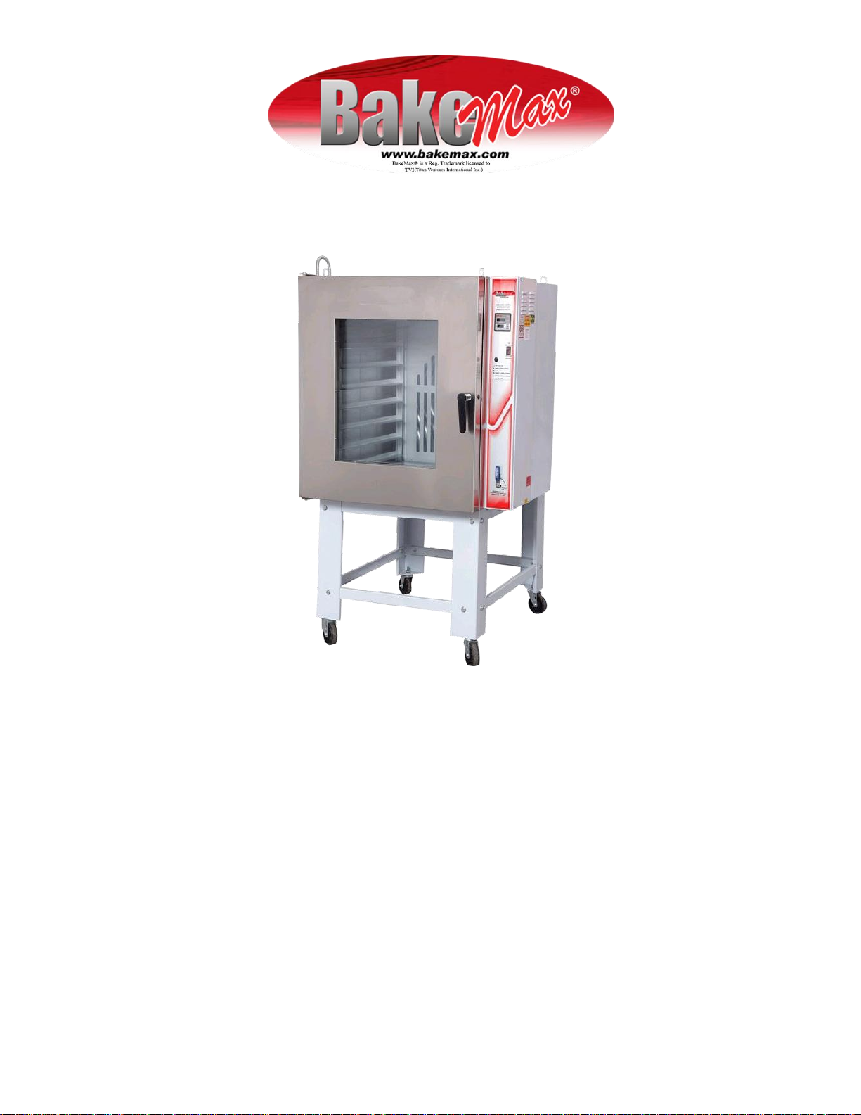
2) STEAM CIRCUIT
The electronic controller is equipped with a "timer" that controls how long the solenoid valve is to be kept open when operated manually.
Time is programmed by the user. (Check electronic controller configurations steam time).
After time controlled by the "timer" is over, LED turns off automatically, indicating that solenoid valve has closed, and not allowing any more
water to come in. Wait for 10 seconds, and then press steam key again in order to repeat steam cycle. If water pressure is too high, a
volume of water above necessary will come in.
ATTENTION!
* Connect water supply for steam generation directly from the water deposit (reservoir)
in order to prevent high pressures from forming, except for those reservoirs or tanks
installed in very high locations.
* Never connect directly to external water utility supply, because of very high pressure
that is generated.
* Observe instructions, excessive water may damage the equipment and compromise
useful life of the solenoid valve.
* Water supply pressure should range between 0.8 and 2.0 Kgf/cm2 . Above 2.0
Kgf/cm" it is recommended to provide a pressure-reducing valve.
When installing the equipment, electrician should bear in mind the following:
1) We recommend using a circuit breaker in accordance with technical
specifications.
2) Direction that the motor should turn to move the turbine is counterclockwise,
when facing front of the oven. Should engine start turning the other way around,
it is necessary to reverse a phase.
3) Provide ground wiring for the oven (we recommend using 2.5mm2 wires). It is the
customer's responsibility if it is not possible to install it.
4) Incorrect installation can cause malfunctioning to your oven.
Note: Grounding wire can be found at the rear side of the switchboard.
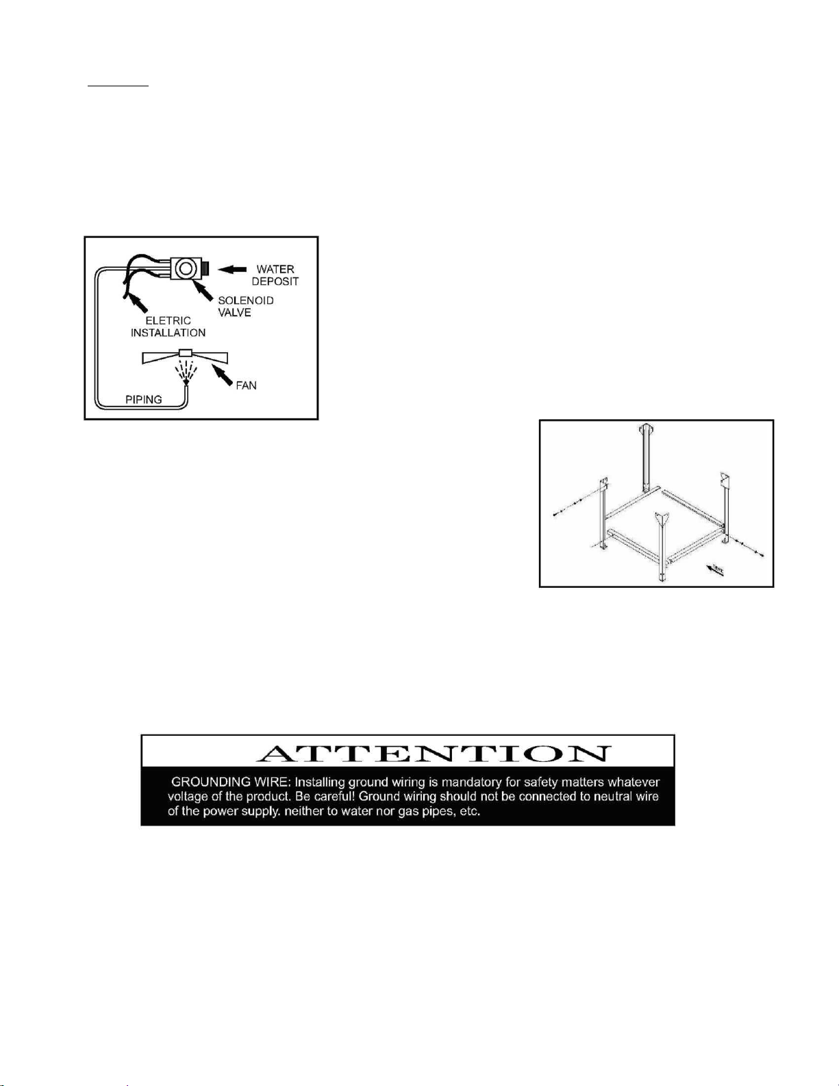
4) ASSEMBLING THE SUPPORTING RACK
This supporting rack is supplied disassembled only for models BMCOE04/06.
In order to assemble it correctly, follow steps shown in the drawing below:

Model
3 phase Source
Net Weight
Gross Weight
(Kg)
(Kg)
BMCOE04
220=45A/380=25A
160
200
BMCOE06
220=45A/380=25A
160
200
BMCOE08
220=73A/380=45A
245
335
BMCOE10
220=87A/380=50A
260
360
Model
Power
Consumption
Heating
Capacity
(KW / h)
Time
BMCOE04
9.5 Kw
4.5 Kw
8 min
BMCOE06
9.5 Kw
4.5 Kw
8 min
BMCOE08
16.0 Kw
7.5 Kw
10 min
BMCOE10
16.0 Kw
8.5 Kw
10 min
Model
Amount of 50-g
Dimensions of
Amount of
Production of
Cooking
Time
Rolls of Bread
the Baking Pans
Baking Pans
50-g rolls / h
( min
BMCOE04
120
58 x 70
4
300 x 360
15 a 18
BMCOE06
150
58 x 70
5
375 x 450
15 a 18
BMCOE08
240
58 x 70
8
600 x 720
15 a 18
BMCOE10
300
58 x 70
10
750 x 900
15 a 18
Model
Width
Width not
Width
Width not
Depth
including
including
including
including
Switchboard
Switchboard
Base
Base
( mm )
( mm )
( mm )
( mm )
( mm )
BMCOE04
940
820
1530
580
1300
BMCOE06
940
820
1610
660
1300
BMCOE08
980
860
1700
1160
1470
BMCOE10
980
860
1770
1000
1470
TRANSPORT
The oven is equipped with four handles on the top so it can be loaded and unloaded. Whenever loading or unloading always use
hydraulic beams or hoists to prevent accidents and damages to the equipment
RECEIVING
We recommend extra care in inspecting the equipment in order to identify any damages that may have been caused during its
transportation, such as: - Broken or dented parts.- Parts missing.
Any damages that might have been caused during transportation should be communicated to the transporting company and to
the manufacturer.
UNPACKING
With the help of a crowbar, remove battens that involve the packaging. After removing equipment from the package, perform visual
inspection in order to check for any possible damages caused during transportation.
TECHNICAL FEATURES /DIMENSIONS
Dimensions:
ELECTRIC SUPPLY
Voltage of the oven: check whether voltage of the equipment is the same of your electric supply.
Wall socket: socket where oven is to be connected should be a mono-phase or 3-phase fix plug, dimensioned for the nomina l
current of the protection circuit ( thermal-electrical breaker), allowing full exemption of plug pins, without any clearances, so that sharp
live parts cannot be touched by human hand.
Socket wiring: they should be rigorously in accordance with their respective compensations as described in your local electrical
specifications guide. Should you have any doubts consult a specialized electrician.
Protection: at the circuit where oven is to be plugged to, there must be a thermal-electrical circuit breaker as per the table below.

Model
Voltage
Motor
Power
Resistance
Power
Protection Circuit Breaker
Recommended (3-pole)
BMCOE04
3 phase 220v
1/4 cv
9 Kw
15A
3 phase 380v
1/4 cv
9 Kw
15A
BMCOE06
3 phase 220v
1/4 cv
9 Kw
15A
3 phase 380v
1/4 cv
9 Kw
15A
BMCOE08
3 phase 220v
1 cv
15 Kw
25 A
3 phase 380v
1 cv
15 Kw
15A
BMCOE10
3 phase 220v
1 cv
18 Kw
30 A
3 phase 380v
1 cv
18 Kw
25 A
Ground wiring or Earth wire: ground wire of your oven should be connected to an effective earth cable, thus preventing from
personal risks. Connection to a ground wire is necessary under any voltage, and should not be connected to the neutral wire of the
power supply, neither to the hydraulic, gas or electrical piping, nor the faucets, etc. It is the customer's responsibility if it is not possible
to turn equipment on.
A CONNECTION TO A GROUND WIRING SYSTEM IS MANDATORY.
Electrical extension cords or the like: for no reason whatsoever should you connect any other equipment to the same wall socket.
That can cause an overload on the electrical supply and/or bad contact. Overloads can cause prejudicial heating to insulation of the
connections, the terminals or surroundings of the conductors, and cause damages and it may even burn the installations or the
Power oscillations: if power supply in your establishment presents any oscillations that are not compliant with the variations allowed,
contact your power supplier and ask for its regularization. If that is not possible, install an automatic stabilizer according to the
maximum nominal power.
HYDRAULIC SUPPLY
product.
Water supply: it is necessary to have a fix point for the water supply, preferably an exclusive one and that meets technical
specifications for pressure. Adapt a valve o a garden-like faucet with a 3/4"BSP thread.
INSTALLING
1. Provide for installation site:
- Box with fuse and circuit breaker.
- Electric wall socket check power supply: wall socket.
- Grounding wire check power supply: wall socket.
- Water supply point with valve
2. Perfect leveling of the equipment should be observed.
ATTENTION! - Always allow a 20-cm clearance between oven and walls in order to obtain a good performance from your oven and to
make sure there is no overheating of the motor. Observe direction of motor rotation. Correct direction is counterclockwise.

HOW TO PUT YOUR EQUIPMENT INTO OPERATION
After observing recommendations described previously as for proper functioning of the equipment, it will be ready to be used.
FUNCTIONING
Automatic Ignition: When the Emergency Key is released, and On/Off is pressed, the automatic ignition process starts, and
resistance will turn on automatically
Steam: It can be activated by pressing switch key ‘6’. Steam will be activated for time programmed with 10-second intervals between
activations.
Lamp: Can be activated by pressing switch key ‘1’; once it has been activated light will only turn off after 8 seconds.
Heating: Whether there is any heating on (resistance ON), that should be indicated by a LED ‘9’ flashing next to the upper displays.
Door Opening: Should the door remain open for more than 3 minutes, a message saying "DOOR" will be displayed and a sound
signal will go off. As soon as the door is closed, automatic ignition will start again.
End of Cooking: As soon as cooking process is over, the equipment will sound an alarm and time displays will start flashing. To turn
it off, press switch key number ‘2’.
Note: Oven doesn't turn off by itself. To turn the equipment off after cooking time is over it is necessary to press On /Off switch key.
SEQUENCE TO TURN OVEN ON:
1- First of all, check whether the oven has been properly plugged to electricity
2- Turn "Emergency Switch Key" and press "On/Off".
3- At this moment, controller will perform automatic ignition of the burner, and display will exhibit the configurations set at the
factory.
To set a new configuration, proceed as follows:
Time and Temperature: To program the temperature, press switch key ‘4’ for approximately 3 seconds; indicator display should start
flashing indicating that the temperature can be programmed by pressing switch keys ‘3’and ‘5’. After you have set the temperature
program, press switch key ‘4’ again, and time indicator will start flashing. That indicates time can be set by pressing switch keys ‘3’ and
‘5’. After that, press switch key ‘4’ again, and the equipment will be back to regular control condition.
NOTE: During programming, if there is a pause longer than 3 seconds, equipment will resume regular control condition.
Steam Time: To adjust steam time, turn oven on pressing key ‘6’, and display on the top will show VAP while display on the bottom will
show the amount to be programmed. Adjust amount with keys ‘3’ and ‘5’ programmed value will be saved after 3 seconds without
pressing the keys. Turbine: Turbine will activate itself 3 seconds after Emergency Switch key and ON/OFF Switch key have been
pressed.
* Following sequence described above, burner flame will light up and go out automatically, always keeping temperature that was
programmed.

COOKING
When oven has reached the temperature desired, proceed as follows:
1- Open oven door. At this moment, micro switch key will automatically turn turbine off.
2- Load batch and close the door. 3 seconds after you have closed the door, turbine will turn on.’6’.
3- Press "STEAM" switch key ‘6’. At this moment, the solenoid valve will open letting water into the chamber for the time
programmed.
4- Program cooking time on the display.
5- Activate switch key 2
6- Wait for sound signal given by the alarm, which should signalize cooking time determined on the "timer" is over.
TEMPERATURES
ATTENTION: Temperatures should not be higher than the ones specified below; otherwise you might not reach the
results you expected.
PASTRY:……………………………120A180°C
For good functioning and long useful life do not use your oven at temperatures higher than 250°C.
ILLUMINATION OF THE OVEN
Two halogen 50W-12V lamp bulbs are used to illuminate the internal chamber of the oven. To replace the bulbs, just remove
setscrews that hold the glass pane of the door. Disconnect the lamps from their plugs, and put new ones there.
Note: Install l amp bulbs with clean hands to prevent dirt or grease from sticking to their glass.
CLEANING THE OVEN
ATTENTION! Never clean glass pane of the door when oven is still warm because that can cause it to break.
Perform external cleaning of the oven with mild soap and clean water. Never use products that may damage painting of the oven
such as solvents, chemical products, steel wool, etc.
SWEET ROLLS: ............................ 150°C
FRENCH ROLLS: .......................... 175°C
TROUBLESHOOTING AND POSSIBLE SOLUTIONS
1- Oven doesn't turn on:
* Check if emergency switch key is unlocked;
* Check fuse;
* Check if oven is connected to power supply;
* Check if there is electric energy being supplied.
2- Steam doesn't work:
* Check if water valve is open;
* Check if there is water being supplied;
3- Turbine doesn't turn on:
* Check if door is completely shut;
* With door open press micro switch key for 5 seconds; if turbine does not turn on, BakeMax®.
4- Lamp doesn't turn on:
* Check if control switch key has been activated by sound signal (1 beep);
* Replace bulbs;
*** Should any of the problems persist, please contact BakeMax®.

220 Volt
3 Phase

 Loading...