

Page 1
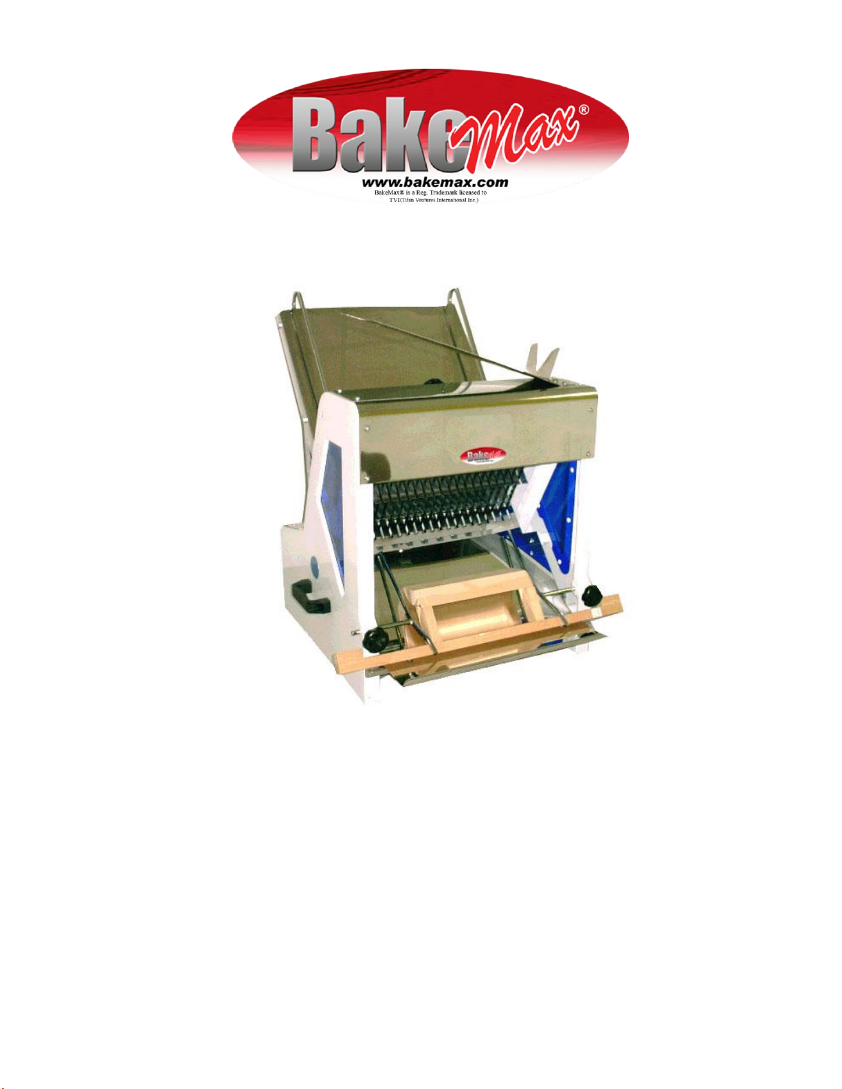
BMGF001 BREAD SLICER
Operations Manual
Page 2

Page 3

BakeMax®
BMGF001 Gravity Feed Slicer
1. INSTALLATION
Put the Slicer on a stable table and make sure the Slicer seats firmly on the table. If the
Slicer vibrates seriously during operation, put paper or rubber underneath the frame of
the Slicer.
2. ELECTRIC CONNECTION
Before making electrical connections, check the specifications on the name plate to
make sure they agree with those of your electrical service.
3. SPECIAL ATTENTION
The operator should not put his fingers into the vibrating knives. The last bread can not
be sliced easily. Please do not try to push the last bread with finger from the chute or to
take out the bread from front.
Please switch off the Slicer when you clean it.
4. CHANGE OF BLADES
When Slicer slices the bread slowly, the blades have become dull and must be changed.
TO DISMANTLE THE BLADES
1. Take off Cover front (3) and Top cover (4).
2. Take off Outgoing Chute (10).
3. Loosen the screws on Bracket (6) (7) and (23).
4. Take out Guide Rod (24) and the Frame for Blades (34) can be taken out.
5. Press Spring (29) to take out Blade one by one.
TO REMOUNT THE BLADES
1. Press Spring (29) to put the blades onto the Frame (34) one by one.
2. Put Frame (34) into position and insert the Guide Rod (24).
3. Tighten the screws on Bracket (6) (7) and (23).
4. Put in Outgoing Chute (10).
5. Mount the Cover front (3) and Top cover (4).
Page 4

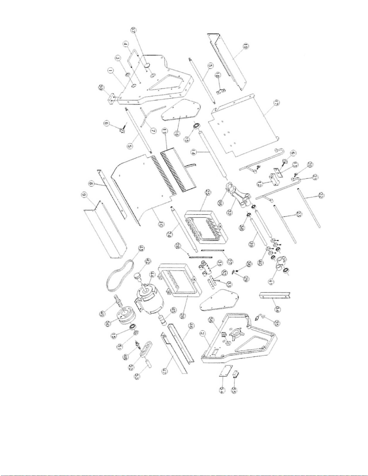
S. NO.
Description
Qty.
NO.
Description
Qty.
1
Machine Wall (left)
1 2 Machine Wall (right)
1
3
Screw Nut
1
4
Handle
2
5
Fixed Lever
3 6 Plastic Lock Bolt
3
7
Division Plate Support Shaft
2 8 L Plate Fixed Block
1 9 Front Cover
1
10
Plate for Receiving Bread
1
11
Pressing Plate for Toast
1
12
Division Plate to Fixed Bread
1
13
Fixed Block
1
14
Fixed Rod for Knife Shelf
1
15
Ball Bearing
4
16
Acrylic Plate
2
17
Upper Slide Board
1
18
Slide Board Fixed Block
3
19
Rear Cover
1
20
Lock Bolt
4
21
Guide Bolt
2
22
Slide Bar Shaft
1
23
Slide Board Shaft
1
24
Slide Board Shaft
1
25
Main Shaft
1
26
Knife Shelf
1
27
Knife
31
28
Fixed Pin
31
29
Knife Blade Fixed Block
62
30
Spring
31
31
Tee Tube
1
32
Driving Shaft
2
33
Driving Rod Link
2
34
L Plate
2
35
Cable
1
36
Linking Bar Joint Block
1
37
Linking Bar Seat (left)
1
38
Shaft Bearing
6
39
Joint Bar
2
40
Bush
4
41
Linking Bar Seat (right)
1
42
Drive Pulley
1
43
Belt
1
44
Motor
1
45
Capacitor
1
46
Motor Seat (front)
1
47
Motor Seat (right)
1
48
Joint Pin
1
49
Drive Pulley
1
50
Drive Pulley
1
51
Screw Nut
1
52
Plastic Linking Rod
1
53
Live Axle
1
54
Switch Plate
1
55
Switch
1
56
L Plate
2
57
Circular Sticker
2
58
Motor Starting
1
BBMGF001 Parts List
Note: Quantities of No. 27,28,29,30 is changeable according to slice thickness.
Page 5
Page 6

 Loading...