

Page 1

DSR
Installer/User Guide
®
Switch
Page 2
European Union Notification
Warning: This is a class A product. In a domestic environment this product may cause radio interference in
which case the user may be required to take adequate measures.
USA Notification
Warning: Changes or modifications to this unit not expressly approved by the party responsible for
compliance could void the user’s authority to operate the equipment.
Note: This equipment has been tested and found to comply with the limits for a Class A digital device,
pursuant to Part 15 of the FCC Rules. These limits are designed to provide reasonable protection against
harmful interference when the equipment is operated in a commercial environment. This equipment
generates, uses and can radiate radio frequency energy and, if not installed and used in accordance
with the instruction manual, may cause harmful interference to radio communications. Operation of this
equipment in a residential area is likely to cause harmful interference, in which case the user will be
required to correct the interference at his/her own expense.
Canadian Notification
This Class A digital apparatus complies with Canadian ICES-003.
Cet appareil numérique de la classe A est conforme à la norme NMB-003 du Canada.
Japanese Notification
Korean Notification
Safety and EMC Approvals and Markings
UL, FCC, cUL, ICES-003, CE, GS, VCCI, MIC, C-Tick, GOST
Safety certifications and EMC certifications for this product are obtained under one or more of the
following designations: CMN (Certification Model Number), MPN (Manufacturer’s Part Number) or
Sales Level Model designation. The designation that is referenced in the EMC and/or safety reports and
certificates is printed on the label applied to this product.
Page 3

DSR
®
Switch
Instal ler/ User Guide
Avocent, the Avocent logo, The Power of Being There, DSR, DSView,
Dambrackas Video Compression and OSCAR are registered trademarks
of A vo cent Corporation or its affiliates in the U .S . and other countries.
All other marks are the property of their respective owners.
© 2008 Avocent Corporation. All rights reserved. 590-686-501D
Page 4
Instructions
This symbol is intended to alert the user to the presence of important operating and maintenance
(servicing) instructions in the literature accompanying the appliance.
Dangerous Voltage
This symbol is intended to alert the user to the presence of uninsulated dangerous voltage within the
product’s enclosure that may be of sufficient magnitude to constitute a risk of electric shock to persons.
Power On
This symbol indicates the principal on/off switch is in the on position.
Power Off
This symbol indicates the principal on/off switch is in the off position.
Protective Grounding Terminal
This symbol indicates a terminal which must be connected to earth ground prior to making any other
connections to the equipment.
Page 5

TABLE OF CONTENTS
Table of Contents
List of Figures ................................................................................................................ vii
List of Tables................................................................................................................... ix
Chapter 1: Product Overview.................... ....... ...... ....... ...... ...... ....... ...... ....... ...... ....... ..... 1
Features and Benefits ........................................................................................................................1
Reduce cable bulk.......................................................................................................................1
Control of virtual media-capable appliances (select models)....................................................2
Access the DSR switch via a standard TCP/IP network.............................................................2
DSView
Chapter 2: Installation ...................................... ...... ....... ...... ...... ....... ............................... 5
DSR Switch Connectivity...................................................................................................................5
Installation Overview.........................................................................................................................5
Getting started..................................................................... ...... ..................................... ............7
Setting up your network..............................................................................................................8
Rack Mounting a DSR Switch............................................................................................................8
Rack mounting safety considerations.........................................................................................8
Connecting the DSR Switch Hardware..............................................................................................9
Configuring the DSR Switch............................................................................................................11
Setting up the built-in web server.............................................................................................11
Setting up the DSView 3 software.............................................................................................11
Connecting to the on-board web interface through a firewall.................................................11
Verifying the Connections................................................................................................................ 13
DSR switch................................................................................................................................13
IQ and serial IQ modules .........................................................................................................13
Adjusting Mouse Settings on Target Devices ..................................................................................13
®
3 management software plug-in.................................................................................2
iii
Chapter 3: Local Port Operation................................................................................... 15
Basic Operations..............................................................................................................................15
Viewing and selecting ports and servers..................................................................................15
Selecting a target device...........................................................................................................15
Soft switching............................................................................................................................16
Viewing the status of your DSR switching system....................................................................16
Page 6

iv DSR Switch Installer/User Guide
Navigating the OSCAR interface......................................... ...... ...... ....................................... ..17
Main Dialog Box Functions.............................................................................................................18
Setting virtual media options.................................................................................................... 19
Managing a KVM session.........................................................................................................20
Setup Dialog Box Functions............................................................................................................21
Changing the display behavior.................................................................................................22
Controlling the status flag........................................................................................................23
Selecting target devices for broadcasting.................................................................................25
Selecting target devices for Scan mode....................................................................................26
Setting local port Screen Saver options....................................................................................27
Setting the keyboard country code............................................................................................28
Configuring network settings....................................................................................................30
Configuring the DSView 3 server IP address...........................................................................31
Assigning device types..............................................................................................................32
Assigning target device names..................................................................................................33
Commands Dialog Box Functions...................................................................................................35
Enabling or disabling Broadcasting.........................................................................................36
Enabling or disabling Scan mode.............................................................................................36
Viewing and disconnecting user connections...........................................................................37
Displaying version information................................................................................................38
Resetting your PS/2 keyboard and mouse................................................................................40
Sending a ping request....................... ...... ........................................ .................................... .....41
Chapter 4: Web Interface Operations........................................................................... 43
Overview of the DSR Switch On-Board Web Interface...................................................................43
Viewing and Selecting Ports and Servers........................................................................................44
The DSR Explorer Window..............................................................................................................44
Using the side navigation bar...................................................................................................45
Using the top option bar ...........................................................................................................46
Launching a KVM Session...............................................................................................................46
Managing the DSR Switch On-Board Web Interface ......................................................................47
Upgrading IQ modules.............................................................................................................47
Managing USB speed ...............................................................................................................48
Rebooting the appliance...........................................................................................................48
Page 7

Table of Contents v
Managing local accounts..........................................................................................................48
Access levels .............................................................................................................................48
Preemption levels......................................................................................................................49
Configuring virtual media........................................................................................................50
Virtual media session settings ..................................................................................................50
Managing Device Properties...........................................................................................................52
Viewing and changing appliance configuration information...................................................52
Power Controlling Target Devices..................................................................................................53
Configuring LDAP...........................................................................................................................54
LDAP Overview parameters.....................................................................................................54
LDAP Search parameters.........................................................................................................55
LDAP Query parameters..........................................................................................................57
Appliance and Target Device Query Modes.............................................................................58
Setting up Active Directory for performing queries.................................................................61
Chapter 5: The Video Viewer......................................................................................... 63
The Video Viewer Window...............................................................................................................63
Launching a KVM Session...............................................................................................................64
Session time-out....................................... ........................................ .........................................64
Video Viewer Window Features ......................................................................................................64
Changing the toolbar................................................................................................................66
Setting the window size.............................................................................................................66
Adjusting the view.....................................................................................................................66
Adjusting color depth................................................................................................................68
Additional video adjustment.......................... ..... ...... ........................................ ..... ...................68
Target video settings.................................................................................................................69
Contrast and brightness............................................................................................................70
Detection thresholds....................................................... ..... ........................................ .............70
Block Noise Threshold and Pixel Noise Threshold ..................................................................70
Automatic video adjustment......................................................................................................70
Refresh Image...........................................................................................................................71
Video Test Pattern ....................................................................................................................71
Adjusting mouse options...........................................................................................................71
Cursor type ...............................................................................................................................71
Mouse scaling...........................................................................................................................73
Page 8

vi DSR Switch Installer/User Guide
Vendor-specific video settings..................................................................................................73
Mouse alignment and synchronization.....................................................................................73
Avocent Mouse Sync ........................................................................................................................74
Using Virtual Media........................................................................................................................75
Requirements ............................................................................................................................75
Sharing and preemption considerations...................................................................................75
Virtual Media dialog box..........................................................................................................76
Opening a virtual media session...............................................................................................76
Closing a virtual media session................................................................................................79
Using Keyboard Pass-through.........................................................................................................79
Using Macros...................................................................................................................................80
Saving the View................................................................................................................................80
Closing a Video Viewer Window Session ........................................................................................80
Chapter 6: Terminal Operations ................................................................................... 81
The Console Menu...........................................................................................................................81
Network Configuration....................................................................................................................81
Other Console Main Menu Options.................................................................................................83
Security Configuration .............................................................................................................83
Firmware Management ............................................................................................................84
Enable Debug Messages...........................................................................................................84
Restore Factory Defaults..........................................................................................................84
Reset Appliance ........................................................................................................................84
Exit............................................................................................................................................84
Appendices..................................................................................................................... 85
Appendix A: Flash Upgrades...........................................................................................................85
Appendix B: Using the DSR Remote Operations Software..............................................................88
Appendix C: Using Serial IQ Modules............................................................................................ 96
Appendix D: UTP Cabling.............................................................................................................100
Appendix E: Cable Pinout Information.........................................................................................102
Appendix F: Technical Specifications...........................................................................................104
Appendix G: Sun Advanced Key Emulation ..................................................................................117
Appendix H: Technical Support.....................................................................................................119
Index............................................................................................................................. 121
Page 9

LIST OF FIGURES
List of Figures
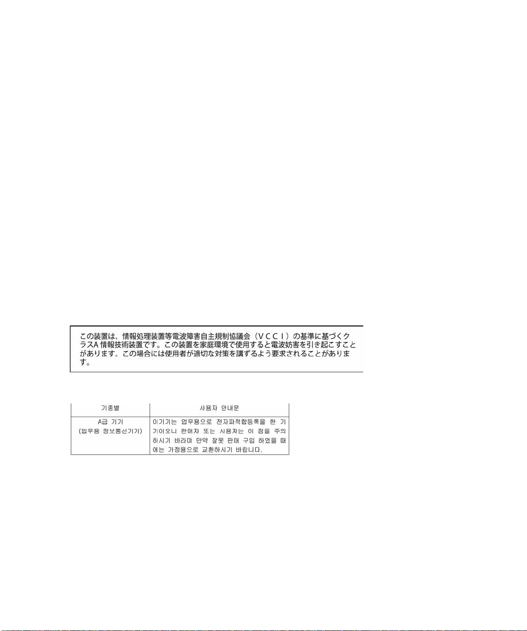
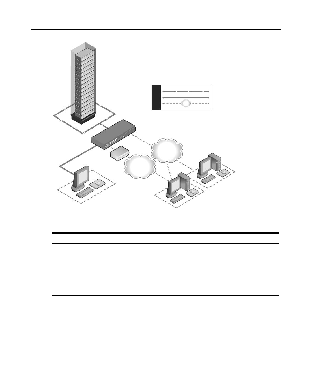
Figure 1.1: Example DSR2035/8035 Switch Configuration .............................................................3
Figure 2.1: Basic DSR Switch Configuration (DSR8035 Switch Shown).........................................6
Figure 2.2: DSR Switch Mounting Diagram.....................................................................................9
Figure 2.3: Typical DSR Switch Firewall Configuration................................................................12
Figure 3.1: OSCAR Interface Main Dialog Box..............................................................................19
Figure 3.2: OSCAR Interface Virtual Media Dialog Box ...............................................................20
Figure 3.3: OSCAR Interface Setup Dialog Box.............................................................................22
Figure 3.4: OSCAR Interface Menu Dialog Box.............................................................................22
Figure 3.5: OSCAR Interface Flag Dialog Box ..............................................................................24
Figure 3.6: Position Flag................................................................................................................24
Figure 3.7: OSCAR Interface Broadcast Dialog Box......................................................................25
Figure 3.8: OSCAR Interface Scan Dialog Box ..............................................................................26
Figure 3.9: OSCAR Interface Screen Saver Dialog Box.................................................................28
Figure 3.10: OSCAR Interface Keyboard Dialog Box....................................................................29
Figure 3.11: OSCAR Interface Network Dialog Box ......................................................................30
Figure 3.12: OSCAR Interface IP Setup Dialog Box ......................................................................31
Figure 3.13: OSCAR Interface DSView IP Dialog Box..................................................................32
Figure 3.14: OSCAR Interface Devices Dialog Box.......................................................................32
Figure 3.15: OSCAR Interface Device Modify Dialog Box.............................................................33
Figure 3.16: OSCAR Interface Names Dialog Box.........................................................................34
Figure 3.17: OSCAR Interface Name Modify Dialog Box..............................................................34
Figure 3.18: OSCAR Interface Commands Dialog Box..................................................................36
Figure 3.19: OSCAR Interface User Status Dialog Box .................................................................37
Figure 3.20: OSCAR Interface Disconnect Dialog Box..................................................................38
Figure 3.21: OSCAR Interface Version Dialog Box........................................................................39
Figure 3.22: DSRIQ Selection Dialog Box......................................................................................39
Figure 3.23: DSRIQ Version Dialog Box........................................................................................40
Figure 3.24: OSCAR Interface Ping Dialog Box ............................................................................41
Figure 4.1: Avocent DSR Explorer Window....................................................................................45
Figure 4.2: On-board Web Interface Appliance Virtual Media Session Settings screen................51
Figure 4.3: LDAP Overview Page in the On-Board Web Interface................................................55
vii
Page 10

viii DSR Switch Installer/User Guide
Figure 4.4: LDAP Search Page in the On-Board Web Interface....................................................56
Figure 4.5: LDAP Query Page in the On-board Web Interface......................................................58
Figure 4.6: Active Directory - KVM User.......................................................................................59
Figure 4.7: Active Directory - KVM Appliance Admin..................................... ..............................60
Figure 4.8: Active Directory - Define Groups.................................................................................61
Figure 5.1: Video Viewer Window (Normal Window Mode) ..........................................................65
Figure 5.2: Manual Video Adjust Dialog Box.................................................................................69
Figure 5.3: Video Viewer Window with Local and Remote Cursors Displayed .............................71
Figure 5.4: Video Viewer Session Options Dialog Box...................................................................74
Figure 5.5: Video Viewer Virtual Media Dialog Box......................................................................77
Figure 6.1: Console Main Menu......................................................................................................82
Figure 6.2: Network Configuration Menu.......................................................................................82
Figure B.1: Using the DSR Remote Operations Software with a DSR Switch................................89
Figure B.2: DSR Remote Operations Window................................................................................92
Figure E.1: Modem Jack ...............................................................................................................102
Figure E.2: Console/Setup Jack.................................................................................................... 102
Figure E.3: SPC Jack ....................................................................................................................103
Page 11

LIST OF TABLES
List of Tables
Table 1.1: Descriptions for Figure 1.1..............................................................................................3
Table 2.1: Descriptions for Figure 2.1..............................................................................................7
Table 2.2: TCP Ports and Functions for the DSR Switch On-Board Web Interface.......................11
Table 2.3: Descriptions for Figure 2.3............................................................................................12
Table 3.1: OSCAR Interface Status Symbols...................................................................................16
Table 3.2: OSCAR Interface Navigation Basics..............................................................................17
Table 3.3: Main Dialog Box Functions...........................................................................................19
Table 3.4: Virtual Media Options....................................................................................................19
Table 3.5: Setup Features to Configure the OSCAR Interface........................................................21
Table 3.6: OSCAR Interface Status Flags.......................................................................................23
Table 3.7: Commands to Manage Routine Tasks for Your Target Devices ....................................35
Table 4.1: On-Board Web Interface Supported Operating Systems and Browsers.........................43
ix
Table 4.2: Descriptions for Figure 4.1............................................................................................45
Table 4.3: Allowed Operations by Access Level..............................................................................49
Table 4.4: Virtual Media Session Settings.......................................................................................50
Table 4.5: Viewing Appliance Information......................................................................................52
Table 5.1: Descriptions for Figure 5.1............................................................................................65
Table 5.2: Descriptions for Figure 5.2............................................................................................69
Table 5.3: Descriptions for Figure 5.3............................................................................................72
Table B.1: Descriptions for Figure B.1...........................................................................................89
Table B.2: Descriptions for Figure B.2...........................................................................................92
Table B.3: DSR Remote Operations Content Area Icons (Servers View) .......................................93
Table B.4: DSR Remote Operations Content Area Icons (Power View).........................................93
Table C.1: Serial IQ Module Pinouts..............................................................................................99
Table D.1: UTP Wiring Standards................................................................................................100
Table E.1: Descriptions for Figure E.1.........................................................................................102
Page 12

x DSR Switch Installer/User Guide
Table E.2: Descriptions for Figure E.2.........................................................................................103
Table E.3: Descriptions for Figure E.3.........................................................................................103
Table F.1: DSR1020/2020/4020/8020 Switch Product Specifications..........................................104
Table F.2: DSR1021/1022 Switch Product Specifications............................................................106
Table F.3: DSR1024 Switch Product Specifications ......................................... ...... ......................108
Table F.4: DSR1030/2030/4030/8030 Switch Product Specifications..........................................110
Table F.5: DSR1031 Switch Product Specifications ......................................... ...... ......................112
Table F.6: DSR2035/8035 Switch Product Specifications............................................................114
Table G.1: Sun Key Emulation ....................................................................................................117
Table G.2: PS/2-to-USB Keyboard Mappings...............................................................................118
Page 13

CHAPTER
Product Overvi ew
1
Features and Benefits
1
Avocent DSR
control of data center servers and virtual media, and to facilitate the OA&M (operations, activation
and maintenance) of remote branch offices where trained operators may be unavailable. The DSR
switches provide enterprise customers with a significant reduction of cable volume, secure remote
access and flexible server management from anywhere at anytime.
The DSR KVM switch family has several available options depending on the model:
• a rack mountable keyboard , video and mo use (KVM) switch, configu rable for analog (local) o r
digital (remote) connectivity
• video resolutions supported up to 1280 x 1024 for remote users
• enhanced video quality of up to 1600 x 1200 available to local users via the video port
• optional support for managing intelligent pow er devi ces
• virtual media capability accessed through USB ports
• accessibility to target devices across 10/100 or 1000BaseT (some models) LAN port(s)
• a MODEM port that supports V.34, V.90 or V.92-compatible modems that may be used to
access the switch when an Ethernet connection is not available
The IP-based DSR switches give you flexible target device m anagement control from anywhere in
the world.
®
switches combine analog and digital technology to provide flexible, centralized
Reduce cable bulk
With server densities continually increasing, cable bulk remains a major concern for network
administrators. The DSR switches significantly reduce KVM cable volume in the rack by utilizing
the innovative IQ module and single, industry-standard Unshielded Twisted Pai r (UTP) cabl ing.
This allow s a higher server density while providing greater airflow and cooling capacity.
The IQ module is powered directly from the target device and provides Keep Alive functionality
when the switch is not powered.
Page 14

2 DSR Switch Installer/User Guide
The serial IQ module is a DCE device that provides the primary interface between a serial device
and a DSR switch. It provides VT100 terminal emulation, break suppression and port history in a
compact, convenient module.
Control of virtual media-capable appliances (select models)
The virtual media enabled DSR switches allow you to view, move or copy data located on virtual
media to and from any server. Manage remote systems more efficiently by allowing operating
system installation, operating system recovery, hard drive recovery or duplication, BIOS updating
and server backup.
Virtual media can be connected directly to the switch using USB ports located on the switch. In
addition, virtual media may be connected to any remote workstation that is running DSView
management software and is connected to the DSR switch using an Ethernet connection.
NOTE: Virtual media is available on the following models: DSR1030/2030/4030/8030/1031/2035/8035.
NOTE: To open a virtual media session with a server, the server must first be connected to a virtual media
enabled switch using a virtual media capable IQ module (USB2 or USB2L).
Access the DSR switch via a standard TCP/IP network
The Avocent DSR switches provide agentless remote control and access. No special software or
drivers are required on the attached, or client, computers.
®
3
DSView
NOTE: The client connects to the server housing the DSView 3 management software using an Internet browser.
For modem access, you must install DSR Remote Operations software included on the DSView 3 software
CD-ROM (see the DSView 3 Installer/User Guide for more information).
Users access the DSR switch and all attached systems via Ethernet or using a V.34, V.90 or V.92
modem from a client computer. Clients can be located any where a valid networ k connection exists.
®
3 management software plug-in
The DSView 3 software may be used with the DSR switch to allow IT administrators to remotely
access, monitor and control target devices on multiple platforms through a single, web-based user
interface. For more information, see the DSView 3 Software Plug-In for DSR Switches Technical
Bulletin.
Page 15
Chapter 1: Product Overview 3
5
6
7
8
10
9
4
3
2
1
Figure 1.1: Example DSR2035/8035 Switch Configuration
Table 1.1: Descriptions for Figure 1.1
Number Description Number Description
1 CAT 5 Connection 6 Telephone Network
2 KVM Connection to the Switch 7 Ethernet
3 Remote IP Connection 8 DSView 3 Software Server
4 DSR Switch 9 Analog User (OSCAR Graphical User Interface)
5 Modem 10 Digital User (Computer with Internet browser)
Page 16

4 DSR Switch Installer/User Guide
Page 17

CHAPTER
Installation
2
DSR Switch Connectivity
A DSR switching system transmits keyboard, video and mouse (KVM) information between
operators and target devices attached to the switch over a network using either an Ethernet or
modem connection.
The DSR switch uses TCP/IP for communication over Ethernet. Although 10BaseT Ethernet may
be used, Avocent recommends a dedicated, switched 100BaseT or 1000BaseT network for
switches that support it.
The DSR switch uses the Point-to-Point Protocol (PPP) for communication over a V.34, V.90 or
V.92 modem. You can perform KVM switching tasks by using the on-board web interface, the
DSR Remote Operations software or the DSView 3 software.
5
For more information on the DSView 3 software, visit www.avocent.com or see the DSView 3
Installer/User Guide.
Installation Overview
The general procedure for setting up and installing a DSR switch is as follows:
• Unpack the switch and verify that all components are present and in good condition.
• Make all hardware connections between the power source, switch, target devices, optional
power control device(s), the Ethernet and the optional modem connection.
• Turn on the power and verify that all connections are working.
• Configure the DSR switch’s IP address using the console menu interface or
DSView
• Use the on-board web interface or DSView 3 software to configure the DSR switch. See the
DSV iew 3 Installe r/User Guide for more infor mati on.
• Make the appropriate mouse setting adjustments.
3 software. See the DSView 3 Installer/User Guide for more information.
Page 18
6 DSR Switch Installer/User Guide
1
6
4
5
3
2
10
8
11
12
13
7
9
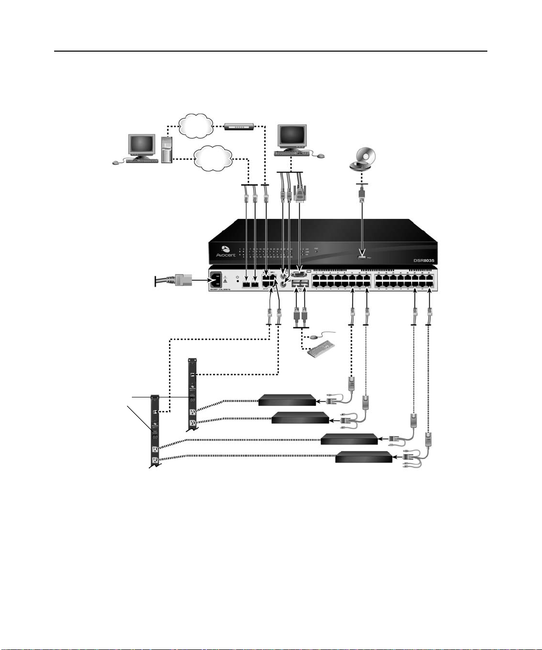
Figure 2.1 illustrates a basic configuration for the DSR switch, us ing the DSR8035 model for the
example. Descriptions follow in Table 2.1.
Figure 2.1: Basic DSR Switch Configuration (DSR8035 Switch Shown)
Page 19

Table 2.1: Descriptions for Figure 2.1
Number Description Number Description
1 Digital User 8 Power Cord
2 Telephone Network 9 Ports 1-32
3 Network 10 Local USB Connections
4 Modem 11 Power Control Device*
5 Analog User 12 Servers 1-32
6 External Virtual Media 13 IQ Modules PS/2, USB**, Sun and serial adaptors are
7 DSR8035 Switch
*If you are using a PM Intelligent Power Distribution Unit (IPDU), use the provided adapter.
**To open a virtual media session with a server, the server must first be connected to the switch using a
virtual media-capable IQ module (USB2 or USB2L).
Getting started
Chapter 2: Installation 7
available.
Before installing your DSR switch, refer to the followin g lists to ensure you have all items that
shipped with the DSR switch, as well as other items necessary for proper installation.
NOTE: While it is possible to use two DSR switches in a cascaded configuration, it can cause function conflicts
and limit the advanced features of the switch. As a result, Avocent does not recommend this configuration.
Supplied with the DSR switch
• Local country power cord
• Rack mounting brackets (depending on switch model)
• Rack Mounting Bracket Quick Installation Guide (depending on switch model)
• DSR Switch Quick Installation Guide
• Either of the following:
• Two ribbon cables with RJ-45 connectors at each end
One RJ-45 to DB-9 (male) adaptor for the modem connection
One RJ-45 to DB-9 (female) adaptor for the SETUP, CONSOLE or 10101 port
-or-
• One null modem cable
Page 20

8 DSR Switch Installer/User Guide
Additional items needed
• One IQ module per target server or serial IQ module per serial device
• One UTP patch cable per IQ module (4-pair UTP, up to 50 meters)
• UTP patch cable(s) for network connectivity (4-pair UTP, up to 50 meters)
• One USB2 or USB2L IQ module per target server for virtual media sessions
• (Optional) DSView 3 software
• (Optional) V.34, V.90 or V.92-compatible modem and cables
• (Optional) power control device(s)
Setting up your network
The DSR switching system uses IP addresses to uniquely identify the switch and the target devices.
The DSR switch family supports both Dynamic Host Configuration Protocol (DHCP) and static IP
addressing. Avocent recommends that IP addresses be reserved for each switch and that they
remain static while the switches are connected to the network.
For additional information on setting up the DSR sw itch using the DSView 3 software, and for
information on how the DSR switch uses TCP/IP, see the DSView 3 Installer/User Guide.
Rack Mounting a DSR Switch
A rack mounting kit is supplied with each DSR switch. You may either place the DSR switch on
the rack shelf or mount the switch directly into an Electronic Industries Alliance (EIA)
standard
Most DSR switches may be rack mounted in a 1U configuration. The DSR switch family does not
support a 0U configuration.
rack.
Rack mounting safety considerations
• Rack Loading - Overloading or uneven loading of racks may result in shelf or rack failure,
causing damage to equipment and possible personal injury. Stabilize racks in a permanent
location before loading begins. Mount components beginning at the bottom of the rack, then
work to the top. Do not exceed your rack load rating.
• Power Considerations - Connect on ly to the p ower source specified o n the unit. Wh en multiple
electrical components are installed in a rack, ensure that the total component power ratings do
not exceed circuit capabilities. Overloaded power sources and extension cords present fire and
shock hazards.
• Elevated Ambient Temperature: If installed in a closed rack assembly, the operating
temperature of the rack environment may be greater than room ambient. Use care not to exceed
the rated maximum ambient temperature of the switch.
• Reduced Air Flow: Install the equipment in the rack so that the amount of airflow required for
safe operation of the equipment is not compromised.
Page 21
Chapter 2: Installation 9
• Reliable Earthing: Maintain reliable earthing of rack mounted equipment. Pay particular
attention to supply connections other than direct connections to the branch circuit (for
example, use of power strips).
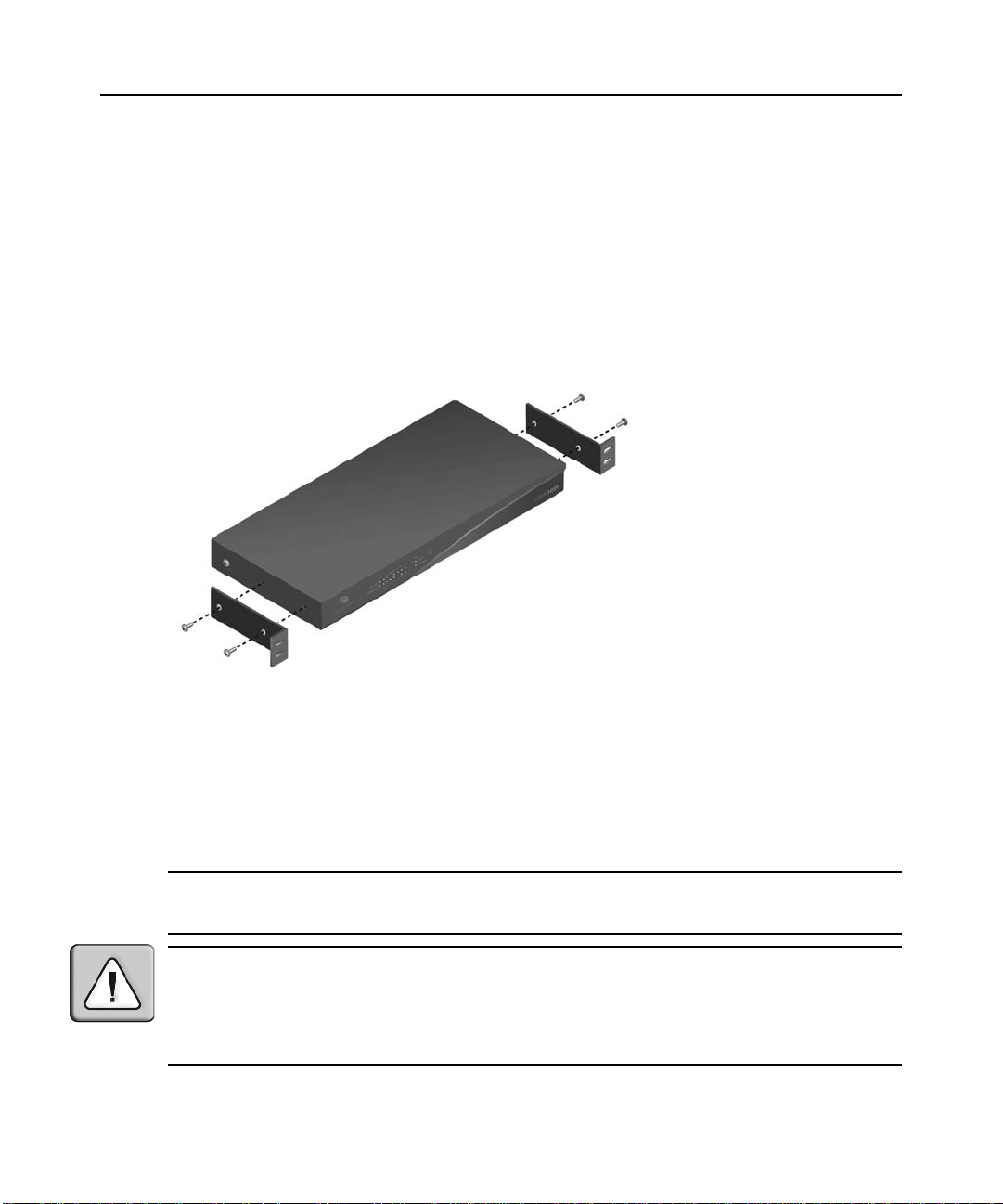
T o install the rack mounting bracket:
1. Remove the two rack mounting screws from each side of the DSR switch.
2. Place the rack mounting brackets next to the switch as illustrated in Figure 2.2.
3. Insert the screws supplied with the rack mounting kit through the holes of the brackets and into
the DSR switch. Tighten the screws securely.
Install the DSR switch into the rack using the approved method of the rack manufacturer.
Figure 2.2: DSR Switch Mounti ng Dia gram
Connecting the DSR Switch Hardware
To connect and power up your DSR switch:
1. Power down the target device(s) that will be part of your DSR switching system. Locate the
power cord that came with the DSR switch and plug the appropriate end into the p ower s ocket
on the rear of the DSR switch. Plug the other end into an appropriate AC wall outlet.
NOTE: To avoid potential video and /or k e y boa r d problems when using Av oc e nt products: If the building
has 3-phase AC power, ensure that the computer and monitor are on the same phase. For best results, they
should be on the same circuit.
WARNING: To reduce the risk of electric shock or damage to your equipment:
- Do not disable the power cord grounding plug. The grounding plug is an important safety feature.
- Plug the power cord into a grounded (earthed) outlet that is easily accessible at all times.
- Disconnect the power from the switch by unplugging the power cord from either the electrical outlet or
the appliance.
- The AC inlet is the main power disconnect.
Page 22

10 DSR Switch Installer/User Guide
2. Disconnect the po we r from the swi tch by unp lugg ing the po wer cord fr om either the electri cal
outlet or the appliance.
3. Plug your VGA monitor and either PS/2 or, if your DSR switch model supports USB, USB
keyboard and mouse cables into the appropriately labeled ports. You must install both a
keyboard and mouse on the local ports or the keyboard will not initialize properly.
4. Plug a compatible IQ module into the appropriate ports on the back of the target server.
5. Choose an available numbered port on the rear of your DSR switch. Plug one end of a UTP
patch cable (4-pair, up to 50 meters) into the selected port and plug the other end into the RJ-45
connector of the IQ module. Repeat this procedure for all servers that are to be connected to
the DSR switch.
NOTE: When connecting a Sun IQ module, you must use a multi-sync monitor in the local port to accommodate
Sun computers that support both VGA and sync-on-green or composite sync.
6. Plug a UTP patch cable from your Ethernet network into the LAN port on the back of your
DSR switch. Network users will access the DSR switch through this port. Repeat this step if
your switch supports multiple LAN ports.
7. (Optional) The DSR switch can also be accessed using an ITU V.92, V.90 or V.34-compatible
modem. T o connect it, p lug one end o f either rib bon cable or the n ull modem cable (whichever
is included with your model of DSR switch) into the MODEM port on the back of your DSR
switch. Plug the other end into the modem. An RJ-45 to DB9 (female) adaptor is provided
should it be necessary.
NOTE: Using a modem connection instead of a LAN connection will limit the performance capability of your
DSR switch.
8. (Optional) De pendin g on t he model, u p to two power cont rol devi ces can be attached to a DSR
switch. To connect a power control device, plug one end of the cable supplied with a DSR
switch compatible power control device into an available SPC port on the DSR switch. Plug
the other end into the power control device. Plug the power cords from the target servers into
the power control device power outlets. Plug the power control device into a grounded AC
wall outlet. Repeat this step for any additional available SPC ports.
T o connect local virtual media:
Connect the virtual media to an available USB port on the DSR switch.
NOTE: For all virtual media sessions, you must use a USB2 or USB2L IQ module.
To connect a serial IQ module to a serial device:
1. Attach the serial IQ module 9-pin serial connector to the serial port of the device to be
connected to your DSR switch.
2. Attach one end of the UTP patch cable to the RJ-45 connector o n the IQ-SRL modu le. Connect
the other end of the UTP patch cable to the desired port on the back of your DSR
switch.
Page 23

NOTE: The serial IQ module is a DCE device and only supports VT100 terminal emulation.
3. Connect the power supply to the power connector on your serial IQ module. The cable
expander can be used to power up to four serial IQ modules from a single power supply.
4. Connect the ser ial IQ modu le power supp ly to a groun ded AC wall out let. Power up your seri al
device. See the
Using Serial IQ Modules on page 96 for more information.
Configuring the DSR Switch
Once all mechanical connections have been made, you will need to configure the switch for use in
the overall switching system. This can be accomplished in three ways.
To configure the DSR switch using the console interface:
See Chapter 6 for detailed instructions.
T o configure the DSR switch using the DSView 3 software:
See the DSView 3 Installer/User Guide for detailed instructions.
To configure the DSR switch using the OSCAR® graphical user interface:
See Configuring network settings on page 30 for de tailed inst ructions on u s ing the OSCAR
interface to configure initial network setup.
Chapter 2: Installation 11
Setting up the built-in web server
You can access the DSR switch via an embedded web server that handles most day-to-day
switching tasks. Before using the web server to access the switch, first specify an IP address
through the SETUP, CONSOLE or 10101 port on the back panel of the switch. See
detailed instructions on using the on-board web interface for switching.
Setting up the DSView 3 software
See the DSView 3 Installer/User Guide, or refer to the DSView 3 Software Online Help.
Connecting to the on-board web interface through a firewall
For DSR switch installations that use the on-board web interface for access, four ports must be
opened in a firewall if outside access is desired.
Table 2.2: TCP Ports and Functions for the DSR Switch On-Board Web Interface
TCP Port
Number
80 Used for the initial downloading of the Avocent Video Viewer (for downloading the Java applet)
443 Used by the web browser interface for managing the DSR switch and launching KVM sessions
Function
Chapter 4 for
Page 24
12 DSR Switch Installer/User Guide
1
2
3
5
4
Table 2.2: TCP Ports and Functions for the DSR Switch On-Board Web Interface (Continued)
TCP Port
Number Function
2068 Transmission of KVM session data (mouse & keyboard) or transmission of video on x030 and
x035 model DSR switches
8192 Transmission of KVM session data (video) except for x030 and x035 model DSR switches
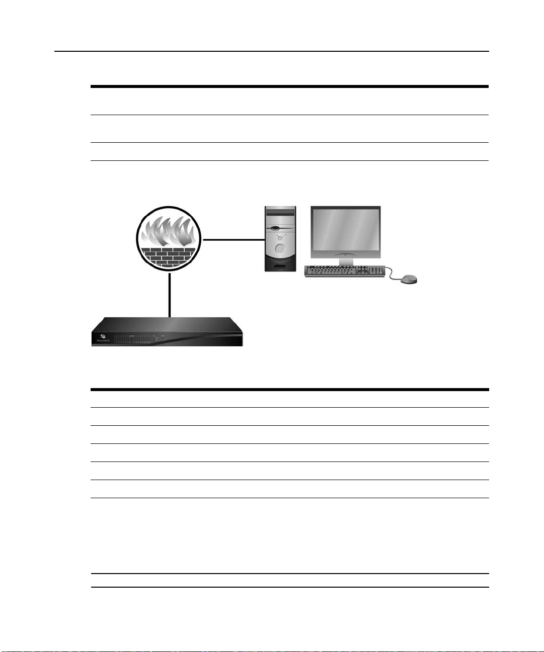
In a typical configuration, as shown in Figure 2.3, the user’s computer is located outside of the
firewall, and the DSR switch resides inside the firewall.
Figure 2.3: Typical DSR Switch Firewall Configuration
Table 2.3: Descriptions for Figure 2.3
Number Description
1 DSR Switch
2 Firewall
3 User’s Computer
4 Firewall Forwards HTTP Requests and KVM Traffic to the DSR Switch
5 User Browses to Firewall’s External IP Address
To configure the firewall:
To access the DSR switch from outside a firewall, conf igure yo ur fi rewall to forward ports 80, 443,
2068 and 8192 from its external interface to the KVM switch through the firewall’s internal
interface. Consult the manual for your firewall for specific port forwarding instructions.
NOTE: Port 8192 does not have to be forwarded for DSR1031, DSRx030 and DSRx035 switches.
Page 25

To connect to the DSR switch on-board web interface:
Open a web browser and enter the external IP address of the firewall. The DSR Explorer will open
and prompt you to login.
Verifying the Connections
DSR switch
The front panel of the DSR switch features LEDS indicating the Ethernet connection for both
LAN1 and LAN2 (if applicable), as well as LEDS that indicate the target device status for
each
port.
Ethernet connection LEDS
• The green LED, labeled Link, illuminates when a valid connection to the network is
established at the maximum supported rate and blinks when there is activity on the port.
• The amber LED illuminates when you are communicating at a slower rate when using an
Ethernet connection.
• If neither LED is illuminated, connection speed is at a rate of 10 Mbps.
T arget device status LEDS
• A green LED illuminates when the attached target device has power.
• An amber LED illuminates when that port is selected.
• The LEDs blink during a firmware upgrade.
Chapter 2: Installation 13
IQ and serial IQ modules
Typically, IQ modules feature two green LEDs: a POWER LED and a STATUS LED.
•The POWER LED indicates that the attached module is powered.
•The STATUS LED indicates that a valid selection has been made to a DSR switch.
The serial IQ module prevents a serial break from the attached device if the module loses power.
However, a user can generate a serial break with the attached device by pressing
accessing the Terminal Applications menu.
Adjusting Mouse Settings on Target Devices
Before a computer connected to the DSR switch can be used for remote user control, you must set
the target mouse speed and turn off acceleration. For machines running Microsoft
(Windows NT®, 2000, XP, Server 2003), use the default PS/2 mouse driver.
To ensure that the local mouse movement and remote cursor display remain in sync, mouse
acceleration must be set to “none” for all user accounts accessing a remote system through a KVM
switch. Mouse acceleration must also be set to “none” on every remote system. Special cursors
Alt-B after
®
Windows®
Page 26

14 DSR Switch Installer/User Guide
should not be used and cursor visibility options, such as pointer trai ls, Ctrl key cursor location
animations, cursor shadowing and cursor hiding, should also be turned off.
For more information about setting mouse movement and cursor features for use with Avocent
hardware products and DSView
consult the Mouse and Pointer Settings guide.
NOTE: If you are not able to disable mouse acceleration from within a Windows operating system, or if you do
not wish to adjust the settings of all your servers, newer versions of the DSView 3 software include the Tools -
Single Cursor Mode command available in the Video Viewer window. This command places the Video Viewer
window into an “invisible mouse” mode which allows you to manually toggle control between the mouse pointer
on the target system being viewed and the mouse pointer on the client running DSView 3 software.
3 management software, please visit www.avocent.com and
Page 27

CHAPTER
Local Port Oper ation
3
Most DSR switch models include a local port on the back. This port enables you to connect a
keyboard, monitor and mouse to the switch for direct access. The DSR switches include the
OSCAR
Basic Operations
Viewing and selecting ports and servers
Use the Main dialog box to view, configure and control target devices in the DSR switching
system. You may view the target devices by name, port or by the unique Electronic ID (EID)
embedded in each IQ module. You will see an OSCAR interface-generated port list by default
when you first launch the OSCAR interface.
graphical user interface for configuring your system and selecting target devices.
15
The Port column indicates the port to which a target device is connected.
Selecting a target device
Use the Main dialog box to select a target device. When you select a target device, the DSR switch
reconfigures the keyboard and mouse to the settings for the selected target device.
To select a target device:
Double-cl i ck the target device name, EID or port number.
-or-
If the display order of your list is by port (the Port button is de pressed), type the port number and
press
Enter.
-or-
If the display order of your list is by na me or EID (the Name or EID button is depressed), type the
first few letters of the name of the target device or the EID number to establish it as unique and
press
Enter.
NOTE: If OSCAR Authentication has been enabled, an “Authenticating” screen will appear after you select a
target device because the DSR switch is confirming your access to that target device. If you are denied access to
the target device, a message will appear saying that you can not view that particular target device.
Page 28
16 DSR Switch Installer/User Guide
To select the previous target device:
Press Print Screen and then Backspace. This key combination toggles you between the previous
and current connections.
To disconnect from a target device:
Press Print Screen and then Alt+0 (zero). This leaves the user in a free state, with no target device
selected. The status flag on your desktop displays Free.
Soft switching
Soft switching is the ability to switch target devices using a hotkey sequence. You can soft switch
to a target device by pressing
number. If you have set a Screen D el ay Ti me and y ou p ress the key sequences befo re that time h as
elapsed, the OSCAR interface will not display.
T o soft switch to a target device:
Press Print Screen. If the disp lay o rder of th e Main dial og is by port (the Port button is depressed) ,
type the por t number and press
-or-
If the display order of the Main dialo g is by n ame (the Name button is depressed), type the first few
letters of the name of the target device to establish it as unique and press
Print Screen and then typing the first few characters of its name or
Enter.
Enter.
To switch back to the previous target device, press Print Screen then Backspace.
Viewing the status of your DSR switching system
The status of target devices in your system is indicated in the far right columns of the Main dialog
box. The following table describes the status symbols.
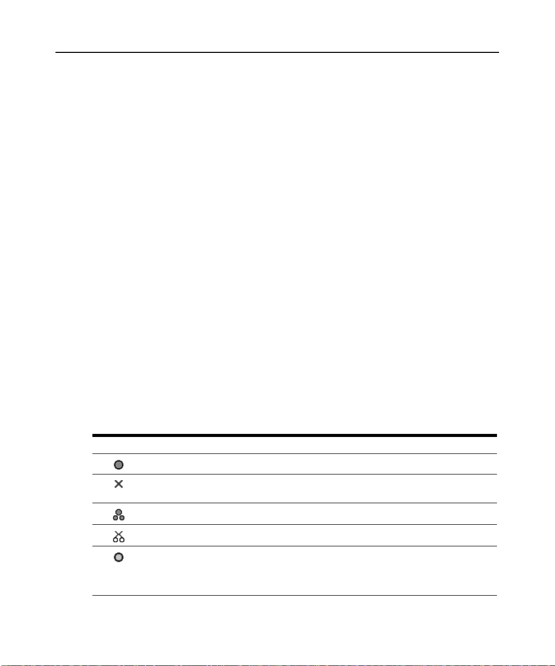
Table 3.1: OSCAR Interface St atus Symbols
Symbol Description
(green circle) Server connected, powered up and the IQ module is online.
Connected target device is powered down or is not operating properly, and the IQ module
is
offline.
Connected switch is online.
Connected switch is offline or not operating properly.
(yellow circle) The designated IQ module is being upgraded. When this symbol displays, do not
cycle power to the DSR switch or connected target devices and do not disconnect IQ modules.
Doing so may render the module permanently inoperable and require the IQ module to be
returned to the factory for repair.
Page 29
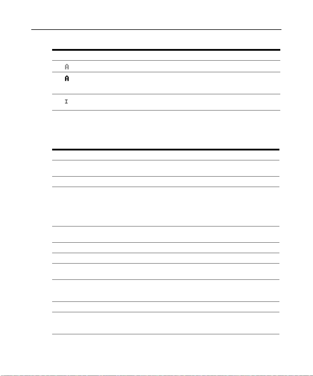
Table 3.1: OSCAR Interface St atus Symbo ls (Continued)
Symbol Description
(green letter) IQ module is being accessed by the indicated user channel.
(black letter) IQ module is blocked by the indicated user channel. For instance, in Figure 3.1,
user B is viewing Forester, but is blocking access to Acton, Barrett and Edie, which are
connected to the same IQ module.
(blue letter) A remote virtual media connection is established to the server connected to the
indicated user channel.
Navigating the OSCAR interface
This table describes how to navigate the OSCAR interface using the keyboard and mouse.
Table 3.2: OSCAR Interface Navigation Basics
Keystroke Function
Print Screen Opens the OSCAR interface. Press Print Screen twice to send the Print
Screen keystroke to the currently selected IQ module.
F1 Opens the Help screen for the current dialog box.
Chapter 3: Local Port Operation 17
Escape Closes the current dialog box without saving changes and returns to the
Alt Opens dialog boxes, selects or checks options and executes actions when
Alt+X Closes current dialog box and returns to previous one.
Alt+O Selects the OK button, then returns to the previous dialog box.
Enter Completes a switch operation in the Main dialog box and exits the
Single-click, Enter In a text box, single-clicking an entry and pressing Enter selects the text for
Print Screen, Backspace Toggles back to previous selection.
Print Screen, Alt+0 (zero) Immediately disengages user from a target device; no target device is selected.
previous one. If the Main dialog box is displayed, pressing Escape closes the
OSCAR interface and displays a status flag if status flags are enabled. See the
Commands Dialog Box Functions on page 35 for more information. In a
message box, pressing Escape closes the pop-up box and returns to the
current dialog box.
used with underlined or other designated letters.
interface.
OSCAR
editing and enables the Left and Right Arrow keys to move the cursor. Press
Enter again to quit the Edit mode.
Status flag displays Free. (This only applies to the 0 (zero) on the keyboard and
not the numeric keypad.)
Page 30

18 DSR Switch Installer/User Guide
Table 3.2: OSCAR Interface Navigation Basics (Continued)
Keystroke Function
Print Screen, Pause Immediately turns on Screen Saver mode and prevents access to that specific
Up/Down Arrows Moves the cursor from line to line in lists.
Right/Left Arrows Moves the cursor between columns. When editing a text box, these keys move
Page Up/Page Down Pages up and down through Name and Port lists and Help pages.
Home/End Moves the cursor to the top or bottom of a list.
Backspace Erases characters in a text box.
Delete Deletes current selection in the Scan list or characters in a text box.
Shift-Del Deletes from the current selection to the end of the list when editing a Scan list.
Numbers Type from the keyboard or keypad.
Caps Lock Disabled. Use the Shift key to change case.
Backspace Erases characters in a text box.
console, if it is password protected.
the cursor within the column.
Main Dialog Box Functions
To access the OSCAR interface Main dialog box:
Press Print Screen to launch the OSCAR interface. The Main dialog box will appear as shown in
Figure 3.1.
NOTE: If OSCAR Authentication has been enabled, you will be prompted to enter a username and password
before you can launch the OSCAR interface.
NOTE: If the DSR switch has been added to a DSView 3 server, then the DSView 3 server will be accessed to
authenticate the user. If the DSR switch has not been added to a DSView 3 server, or if the DSView 3 server
cannot be reached, then the DSR switch local user database will be accessed to authenticate the user. The
default local username is Admin, and there is no password. Usernames in the local user database are
case sensitive.
NOTE: If the Clear, Setup and Commands buttons do not appear on the OSCAR Main dialog box, OSCAR
interface configuration may have been disabled via the DSView 3 management software. For more information,
please see the DSView 3 Software Installer/User Guide.
Page 31

Figure 3.1: OSCAR Interface Main Dialog Box
Table 3.3: Main Dialog Box Functions
Button Function
Chapter 3: Local Port Operation 19
VMedia Set virtual media options and make virtual media connections. This option is only available
when a KVM session is in progress on a virtual media enabled DSR switch.
Log Out Disconnect the KVM and user sessions.
Clear Clear all offline IQ modules.
Disconnect Disconnect the KVM session.
Setup Access the Setup dialog box and configure the OSCAR interface.
Commands Access the Commands dialog box.
Setting virtual media options
If your DSR switch has the virtual media option, you can determine the behavior of the switch
during a virtual media session using the options provided in the Virtual Media dialog box.
3.4 outlines the options that can be set for virtual me dia sessions.
Table 3.4: Virtual Media Options
Function Purpose
Appliance Options
Locked Synchronizes the KVM and virtual media sessions so that when a user disconnects a KVM
connection, the virtual media connection to that server is also disconnected. A local user
attempting to switch to a different server is also disconnected.
Table
Page 32

20 DSR Switch Installer/User Guide
Table 3.4: Virtual Medi a Options (Continued)
Function Purpose
Select Local Mapping Options
Reserve Ensures that a virtual media connection can only be accessed with your username and
CD ROM Allows virtual media sessions to the first detected CD-ROM drive. Enable this checkbox to
Mass Storage Allows virtual media sessions to the first detected mass storage drive. Enable this
Write Access Allows a target server to write data to the virtual media during a virtual media session.
that no other user can create a KVM connection to that server. When the associated KVM
session is disconnected, the virtual media session may be disconnected according to the
Locked setting in the Virtual Media dialog box.
establish a virtual media CD-ROM connection to a server. Disable to end a virtual media
CD-ROM connection to a server.
checkbox to establish a virtual media mass storage connection to a server. Disable to end
a virtual media mass storage connection to a server.
Read access is always allowed during a virtual media session.
T o set virtual media options:
1. If the OSCAR interface is not open, press Print Screen to open the Main dialog box.
2. Click VMedia to open the Virtual Media dialog box shown in Figure 3.2.
Figure 3.2: OSCAR Interface Virtual Media Dialog Box
3. Click to enable or disable each of the options. For information about individual settings, see
Table 3.4.
4. Click OK to accept the options you have selected and return to the Main dialog box.
Managing a KVM session
Click Log Out to disconnect the KVM and user sessions.
Page 33

-or-
Click Clear to clear all offline IQ modules.
-or-
Click Disconnect to disconnect a KVM session. If there is an associated Locked virtual media
session, it will be disconnected.
Setup Dialog Box Functions
You can configure your DSR switching system from the Setup dialog box within the OSCAR
interface. Select the Names button when initially setting up your DSR switching system to identify
target devices by unique names. Select the other setup features to manage routine tasks for your
target devices from the OSCAR interface menu.
each of the buttons in the Setup dialog box as shown in Figure 3.3.
Table 3.5: Setup Features to Configure the OSCAR Interface
Feature Purpose
Chapter 3: Local Port Operation 21
Table 3.5 outlines the function accessed using
Menu Change the Main dialog box list sorting option by toggling between numerically by port or
Flag Change display, timing, color or location of the status flag.
Broadcast Simultaneously send mouse movements and keystrokes to multiple target devices.
Scan Set up a custom Scan pattern for multiple target devices.
Screen Saver Set passwords to protect or restrict access or enable the screen saver.
Keyboard Set the keyboard country code to send to Sun servers.
Network Set the IP address, select an Ethernet mode or enable/disable Ping Response.
DSView IP Specify the IP address of a DSView 3 software server for the DSR switch to contact.
Devices Identify the appropriate number of ports on an attached cascade switch.
Names Identify target devices by unique names.
EID number and alphabetically by name. Change the Screen Delay Time before the
OSCAR interface displays after pressing Print Screen.
To access the OSCAR interface Setup dialog box:
1. Press Print Screen to launch the OSCAR interface. The Main dialog box appears.
2. Click Setup to open the Setup dialog box shown in Figure 3.3.
Page 34

22 DSR Switch Installer/User Guide
Figure 3.3: OSCAR Interface Setup Dialog Box
Changing the display behavior
Use the Menu dialog box to change the display order of target devices, change how the OSCAR
interface is invoked or set a Screen Delay Time for the OSCAR interface. This setting alters how
target devices will display in several dialog boxes, including Main, Devices and Broadcast.
To access the OSCAR interface Menu dialog box:
1. If the OSCAR interface is not open, press Print Screen to open the Main dialog box.
2. Click Setup - Menu in the Main dialog box to open the Menu dialog box shown in Figure 3.4.
Figure 3.4: OSCAR Interface Menu Dialog Box
To choose the display order of target devices:
1. Select Name to display target devices alphabetically by name.
-orSelect EID to display target devices numerically by EID number.
Page 35

-orSelect Port to display target devices numerically by port number.
2. Click OK.
Depending on the display meth od s e lect ed, the co rres po nding button will be depressed in the Main
dialog box.
T o change how the OSCAR interface is invoked:
1. Select the checkbox next to one of the listed methods.
2. Click OK.
To set a Screen Delay Time for the OSCAR interface:
1. Type in the number of seconds (0-9) to delay the OSCAR Interface display after you press
Print Screen. Entering 0 will instantly launch the OSCAR interface with no delay.
2. Click OK.
Setting a Screen Delay Time enables you to complete a soft switch without the OSCAR interface
displaying. To perform a soft switch, see the
Controlling the status flag
The status flag displays on your desktop and shows the name or EID number of the selected target
device or the status of the selected port. Use the Flag dialog box to configure the flag to display by
target device name or EID number, or to change the flag color, opacity, display time and location
on the desktop.
Table 3.6 describes each status flag.
Chapter 3: Local Port Operation 23
Soft switching on page 16.
Table 3.6: OSCAR Interface St atus Flags
Flag Description
Flag type by name
Flag type by EID number
Flag indicating that the user has been disconnected from all systems
Flag indicating that Broadcast mode is enabled
To access the OSCAR interface Flag dialog box:
1. If the OSCAR interface is not open, press Print Screen to open the Main dialog box.
2. Click Setup - Flag to open the Flag dialog box shown in Figure 3.5.
Page 36

24 DSR Switch Installer/User Guide
Figure 3.5: OSCAR Interface Flag Dialog Box
To determine how the status flag is displayed:
1. Select Name or EID to determine what information will be displayed.
2. Select Displayed to activate the flag display. After a switch, the flag will remain on the screen
until the user switches to another device. S electing Timed will cause the flag to display for five
seconds when a switch is made and then disappear.
3. Select a flag color under Display Color. The following flag colors are available:
• Flag 1 - Gray flag with black text
• Flag 2 - White flag with red text
• Flag 3 - White flag with blue text
• Flag 4 - White flag with violet text
4. In Display Mode, select Opaque for a solid color flag.
-orSelect Transparent to see the desktop through the flag.
5. To position the status flag on the desktop:
a. Click Set Position to gain access to the Position Flag screen shown in Figure 3.6.
Figure 3.6: Position Flag
b. Left-click on the title bar and drag to the desired location.
c. Right-click to return to the Flag dialog box.
NOTE: Changes made to the flag position are not saved until you click OK in the Flag dialog box.
Page 37

6. Click OK to save settings.
-orClick X to exit without saving changes.
Selecting target devices for broadcasting
The local user can simultaneously control multiple target devices in a system to ensure that all
selected target devices receive identical input. You can choose to broadcast keystrokes and/or
mouse movements independently.
NOTE: You can broadcast to as many as eight target devices at a time (one target device per port).
To access the OSCAR interface Broadcast dialog box:
1. If the OSCAR interface is not open, press Print Screen to open the Main dialog box.
2. Click Setup - Broadcast to open the Broadcast dialog box shown in Figure 3.7.
Chapter 3: Local Port Operation 25
Figure 3.7: OSCAR Interface Broadcast Dialog Box
NOTE: Broadcasting Keystrokes - The keyboard state must be identical for all target devices receiving a
broadcast to interpret keystrokes identically. Specifically, the Caps Lock and Num Lock modes must be the
same on all keyboards. While the switch attempts to send keystrokes to the selected target devices
simultaneously, some target devices may inhibit and thereby delay the transmission.
Broadcasting Mouse Movements - For the mouse to work accurately, all systems must have identical mouse
drivers, desktops (such as identically placed icons) and video resolutions. In addition, the mouse must be in
exactly the same place on all screens. Because these conditions are extremely difficult to achieve, broadcasting
mouse movements to multiple systems may have unpredictable results.
To select the target devices for broadcasting:
1. From the Broadcast dialog box, select the mouse and/or keyboard checkboxes for the target
devices that are to receive the Broadcast commands.
-or-
Page 38

26 DSR Switch Installer/User Guide
Press the Up or Down Arrow keys to move the cursor to the target device. Then press Alt+K to
select the keyboard checkbox and/or
Alt+M to select the mouse checkbox. Repeat for
additional target devices.
2. Click OK to save the settings and return to the Setup dialog box . Click X or press Escape to
return to the Main dialog box.
For information on starting and stopping broadcasting, see Enabling or disabling Broadcasting on
page 36.
Selecting target devices for Scan mode
In Scan mode, the DSR switch automatically scans from port to port (target device to target
device). You can scan multiple target devices, specifying which devices to scan and the number of
seconds that each will display. The scanning order is determined by placement of the target device
in the list. The list is always shown in scanning order. You can, however, choose to display the
target device’s name or EID number by pressing the appropriate button.
NOTE: Scanning is available only to local users.
To add target devices to the Scan list:
1. If the OSCAR interface is not open, press Print Screen to open the Main dialog box.
2. Click Setup - Scan to open the Scan dialog box shown in Figure 3.8.
Figure 3.8: OSCAR Interface Scan Dialog Box
3. Determine the order within the list to add the target device. If there are no target devices in the
Scan list, your cursor will appear in a blank line at the top of the list.
-orT o add a tar get device to the end of the list, place your curs or in the last tar get device entry and
press the
Down Arrow key.
-or-
Page 39

Chapter 3: Local Port Operation 27
To add a target device within an existing list, place your cursor in the line below where you
want to insert a new target device and press
4. Type the first few characters of a target device name or port number to scan. The first match ing
target device will appear in the line.
-orPress the following keyboard commands in the Name, Port or Time column to move through
the list of target devices available to scan.
a. Press Alt+Down Arrow to move the cursor down through the list of target devices.
b. Press Alt+Up Arrow to move the cursor up through the list of target devices.
c. Press Alt+Home to move the cursor to the first target device in the list.
d. Press Alt+End to move the cursor to the last target device in the list.
5. In the Time column, type the number of seconds (from 3-255) of desired time before the scan
moves to the next target device in the sequence.
6. Move the cursor to the next line or press Down Arrow and repeat steps 2-5 for each of the
remaining target devices to be included in the scan pattern.
7. Click OK to save your settings.
To remove a target device from the Scan list:
1. In the Scan dialog box, click the target device to be removed.
2. Press Delete.
-orPress Shift+Delete to remove the selected target device and all entries below it.
3. Click OK to save your settings.
Insert.
For more on starting and stopping scanning, see Enabling or disabling Scan mode on page 36.
Setting local port Screen Saver options
You can use the Screen Saver dialog box to manage the screen saver inactivity time and test the
Screen Saver mode on the local port. If OSCAR Authentication has been enabled, after the
specified Inactivity Time elapses, the local port locks and remains locked until you press any key or
move the mouse. You will then need to log in and reselect a target device to continue.
To access the OSCAR interface Screen Saver dialog box:
1. If the OSCAR interface is not open, press Print Screen to open the Main dialog box.
2. Click Setup - Screen Saver to open the Screen Saver dialog box shown in Figure 3.9.
Page 40

28 DSR Switch Installer/User Guide
Figure 3.9: OSCAR Interface Screen Saver Dialog Box
To set the Screen Saver options:
1. Type the number of minutes for Inactivity Time (from 1-90) to delay activation of password
protection and the screen saver feature.
2. For Mode, select Energy if your monitor is ENERGY STAR
CAUTION: Monitor damage can result from the use of Energy mode with monitors not compliant with
ENERGY STAR®.
®
compliant; otherwise select Screen.
3. (Optional) Click Test to activate the screen saver test, which lasts 10 seconds, then returns you
to the Security dialog box.
4. Click OK to save your settings.
To exit Screen Saver mode and log in to the local port:
1. Press any key or move the mouse.
2. If OSCAR Authentication has been enabled, you will see a login screen. Enter your username
and password and then click OK. If you do not know your usernam e and passwo rd, cont act the
DSView 3 software server administrator.
3. The Main OSCAR interface dialog box will appear where you may select any available
target
device.
T o immediately activate the screen saver:
Press Print Screen, then Pause.
This command sequence works only when the user is connected to a target device.
Setting the keyboard country code
NOTE: Using a keyboard code that supports a language different from that of your DSR switch firmware will
cause incorrect keyboard mapping.
Page 41

Chapter 3: Local Port Operation 29
Sun servers may use keyboard mappings for non-US keyboards. By default, the DSR switch sends
the US keyboard country code to Sun and USB modules attached to target devices, and the code is
applied to the target devices when they are powered up or rebooted. Codes are then stored in the
IQ
module.
Issues may arise when you use the US keyboard country code with a keyboard of another country.
For example, the
keyboard. Sun servers will interpret pressing the
Z key on a US keyboard is in the same location as the Y key on a German
Y key on a German keyboard as pressin g the Z key
when the US keyboard country code is used.
The Keyboard dialog box enables you to send a different keyboard country code than the default
US setting. The specified country code is sent to all target devices attached to the DSR switches
when they are powered up or rebooted, and the new code is stored in the IQ module.
NOTE: If an IQ module is moved to a different target device, the keyboard country code will need to be reset.
See Sun Advanced Key Emulation on page 117 for information on emul ating certa in Sun keys using
a PS/2 keyboard and special considerations for Japanese and Korean Sun USB keyboards.
NOTE: Only local users can view or change keyboard country code settings.
To set the keyboard country code for Sun servers:
1. If the OSCAR interface is not open, press Print Screen to open the Main dialog box.
2. Click Setup - Keyboard to open the Keyboard dialog box shown in Figure 3.10.
Figure 3.10: OSCAR Interface Keyboard Dialog Box
3. Select a country code and click OK to save your settings.
4. Reboot the Sun servers. After rebooting, each Sun server will request the country code setting
stored in the IQ module.
Page 42

30 DSR Switch Installer/User Guide
NOTE: If you wish to reboot the target devices by power-cycling them, you must wait 90 seconds before
rebooting. A soft reboot may be performed without waiting 90 seconds.
Configuring network settings
Use the Network dialog box to set the IP address, select an Ethernet mode or enable or disable the
Ping Response feature.
NOTE: Only Appliance Administrators can make changes to Network dialog box settings. Other users can still
access this dialog box, as well as the IP Setup dialog box, to view information, but they will not be able to make
any changes.
To set the Ethernet Mode:
1. If the OSCAR interface is not open, press Print Screen to open the Main dialog box.
2. Click Setup - Network to open the Network dialog box shown in Figure 3.11.
Figure 3.11: OSCAR Interface Network Dialog Box
3. Select one of the available options in the Ethernet Mode section.
4. Click OK.
NOTE: You must reboot if you change the Ethernet mode. After you change the setting and click OK, the
following message appears: “Changing the Ethernet mode requires a reboot of the appliance. Do you want to
reboot now, or cancel the changes? Warning: Rebooting will disconnect ALL users!” You can then reboot by
clicking Reboot, or cancel the changes by clicking Cancel.
T o enable or disable the Ping Response:
1. If the OSCAR interface is not open, press Print Screen to open the Main dialog box.
2. Click Setup - Network to open the Network dialog box.
3. Select either Enabled or Disabled in the Ping Response section.
Page 43

Chapter 3: Local Port Operation 31
4. Click OK.
For more information on pinging an IP address, see To send a ping request: on page 41.
Configuring the IP address
The IP Setup dialog box allows users to choose either IPv4 mode or IPv6 mode. The default is
IPv4. You can also specify an IP address for the appliance to use.
T o configure the IP address:
1. If the OSCAR interface is not open, press Print Screen to open the Main dialog box.
2. Click Setup - Network to o pen the Network dialo g box, then click Set IP Address... to open the
IP Setup dialog box shown in
Figure 3.12.
Figure 3.12: OSCAR Interface IP Setup Dialog Box
3. Select either IPv4 or IPv6.
4. Either select or deselect the DHCP checkbox.
NOTE: If you select the DHCP checkbox, any information that you enter in the IP Address, Prefix/Netmask and
Gateway fields will be ignored.
5. If you deselected DHCP in step 4, type the desired information in the IP Address, Prefix/
Netmask and Gateway fields.
6. Click OK.
Configuring the DSView 3 server IP address
The DSView IP dialog box allows users to contact and register an unmanaged DSR switch with a
DSView 3 server by specifying the IP address of a DSView 3 server.
T o configure the DSView 3 server IP address:
1. If the OSCAR interface is not open, press Print Screen to open the Main dialog box.
2. Click Setup - DSView IP to open the DSView IP dialog box shown in Figure 3.13.
Page 44

32 DSR Switch Installer/User Guide
NOTE: If the DSR switch is already associated with a DSView 3 server, the following message will appear
instead of the DSView IP dialog box: Feature unavailable: This appliance is already being managed by a DSView
system.
3. Enter the DSView 3 software server IP address that you want to contact in the DSView Server
IP Address field.
4. Enter how often (in minutes) you want the DSR switch to attempt to contact the DSView 3
software server in the Retry Interval field.
5. Click OK.
Figure 3.13: OSCAR Interface DSView IP Dialog Box
Assigning device types
To access the OSCAR interface Devices dialog box:
1. If the OSCAR interface is not open, press Print Screen to open the Main dialog box.
2. Click Setup - Devices to open the Devices dialog box shown in Figure 3.14.
NOTE: The Modify button is available only if a configurable switch is selected.
Figure 3.14: OSCAR Interface Devices Dialog Box
Page 45

Chapter 3: Local Port Operation 33
When the DSR switch discovers a cascaded switch, the numbering format change s from a DS R port
only to [DSR port]-[switch port] to accommodate each target device under that switch.
For example, if a switch is connected to DSR port 6, each target device connected to it would be
numbered sequentially. The target device using DSR port 6, switch port 1, would be 06-01, the
target device using DSR port 6, switch port 2, would be 06-02, and so on.
To assign a device type:
1. In the Device s dialog box, select the desired por t number.
2. Click Modify to open the Device Modify dialog box shown in Figure 3.15.
Figure 3.15: OSCAR Interface Device Modify Dialog Box
3. Choose the number of ports supported by your switch and click OK.
4. Repeat steps 1-3 for each port requiring a device type to be assigned.
5. Click OK in the Devices dialog box to save settings.
NOTE: Changes made in the Device Modify dialog box are not saved until you click OK in the dialog box.
Assigning target device names
Use the Names dialog box to identify target devices by name rather than by port number. The
Names list is always sorted by port order. You can toggle between displaying the name or the EID
number of each IQ module, so even if you move the target device to another port, the name and
configuration will be recognized by the switch.
NOTE: When it is initially connected, a target device will not appear in the Names list until it is powered up. Once
an initial connection has been made, it will appear in the Names list even when powered down.
To access the OSCAR interface Names dialog box:
1. If the OSCAR interface is not open, press Print Screen. The Main dialog box appears.
Page 46

34 DSR Switch Installer/User Guide
2. Click Setup - Names to open the Names dialog box shown in Figure 3.16.
Figure 3.16: OSCAR Interface Names Dialog Box
NOTE: If new IQ modules are discovered by the DSR switch, the on-screen list will be automatically updated.
The mouse cursor will change into an hourglass during the update. No mouse or keyboard input will be accepted
until the list update is complete.
To assign names to target devices:
1. In the Names dialog box, select a target device name or port number and click Modify to open
the Name Mo dify dialog box shown in
Figure 3.17: OSCAR Interface Name Modify Dialog Box
Figure 3.17.
2. Type a name in the New Name box. Names of target devices may contain all
printable
characters.
3. Click OK to transfer the new name to the Names dialog box. Your selection is not saved until
you click OK in the Names dialog box.
Page 47

4. Repeat steps 1-3 for each target device in the system.
5. Click OK in the Names dialog box to save your changes.
-orClick X or pres s Escape to exit the dialog box without saving changes.
NOTE: If an IQ module has not been assigned a name, the EID is used as the default name.
T o list target devices alphabetically by name:
Press Alt+N or click Name in the Main dialog box.
Commands Dialog Box Functions
From the OSCAR interface Commands dialog box, you can manage your DSR switching system
and user connections, enable the Scan and Broadcast modes and update your firmware.
Table 3.7: Commands to Manage Routine Tasks for Your Target Devices
Features Purpose
Chapter 3: Local Port Operation 35
Broadcast
Enable
Scan Enable Begin scanning your target devices. Set up a target device list for scanning in the Setup
User Status View and disconnect users.
Display Versions View version information for the DSR switch as well as view and upgrade firmware for
Reset PS/2 Re-establish operation of PS/2 keyboard and mouse.
Network Ping Ping a specific IP address.
Begin broadcasting to your target devices. Configure a target device list for broadcasting
under the Setup dialog box.
dialog box.
individual IQ modules.
To access the OSCAR interface Commands dialog box:
1. If the OSCAR interface is not open, press Print Screen to open the Main dialog box.
2. Click Commands to open the Commands dialog box shown in Figure 3.18.
Page 48

36 DSR Switch Installer/User Guide
Figure 3.18: OSCAR Interface Commands Dialog Box
Enabling or disabling Broadcasting
To turn Broadcasting on:
1. If the OSCAR interface is not open, press Print Screen to open the Main dialog box.
2. Click Commands to open the Commands dialog box.
3. Select the Broadcast Enable checkbox to activate Broadcasting.
4. From the user station, type the information and perform the mouse movements you wish
to
broadcast.
To turn Broadcasting off:
From the Commands dialog box, clear the Broadcast Enable checkbox.
Enabling or disabling Scan mode
T o start the Scan mode:
1. If the OSCAR interface is not open, press Print Screen to open the Main dialog box.
2. Click Commands to open the Commands dialog box.
3. Select Scan Enable in the Commands dialog box.
4. Click X to close the Commands dialog box.
NOTE: Scanning will begin as soon as the Scan Enable button is selected.
T o cancel Scan mode:
Select a target device if the OSCAR interface is open.
-or-
Page 49

Move the mouse or press any key on the keyboard if the OSCAR interface is not open. Scanning
will stop at the currently selected target device.
-or-
From the Commands dialog box, deselect the Scan Enable checkbox.
Viewing and disconnecting user connections
You can view and disconnect users through the User Status dialog box. The username (U) will
always be displayed; however, you can display either the target device name or EID number to
which a user is connected. If there is no user currently connected to a channel, the user field will be
blank and the Server Name field will display Free.
To view current user connections:
1. If the OSCAR interface is not open, press Print Screen to open the Main dialog box.
2. Click Commands - User Status to open the Us er Status dialog box shown in Figure 3.19.
Chapter 3: Local Port Operation 37
Figure 3.19: OSCAR Interface User Status Dialog Box
To disconnect a user:
1. If the OSCAR interface is not open, press Print Screen to open the Main dialog box.
2. Click Commands - User Status to open the Us er Status dialog box shown in Figure 3.19.
3. Click the letter corresponding to the user to disconnect. The Disconnect dialog box will appear
as shown in
Figure 3.20.
Page 50

38 DSR Switch Installer/User Guide
Figure 3.20: OSCAR Interface Disconnect Dialog Box
4. Click OK to disconnect the user and return to the User Status dialog box.
-orClick X or pres s Escape to exit the dialog box without disconnecting a user.
NOTE: If the User Status list has changed since last displayed, the mouse cursor will turn into an hourglass as
the list is automatically updated. No mouse or keyboard input will be accepted until the list update is complete.
Displaying version information
The OSCAR interface enables you to display the version number of the switch firmware and any
auxiliary devices connected to the switch. This information facilitate s system troubleshooting and
support. For optimum performance, keep your firmware current.
T o display version information:
1. If the OSCAR interface is not open, press Print Screen to open the Main dialog box.
2. Click Commands - Di splay Versions to open the Version dialog box shown in Figure 3.21.
Page 51

Chapter 3: Local Port Operation 39
Figure 3.21: OSCAR Interface Version Dialog Box
3. To view individual DSRIQ module version information, click DSRIQ to open the DSRIQ
Selection dialog box shown in
Figure 3.22.
Figure 3.22: DSRIQ Selection Dialog Box
4. Select a DSRIQ module to view and click the Version button. The DSRIQ Version dialog box
shown in
Figure 3.23 appears.
For more information on loading firmware, refer to Flash Upgrades on page 85.
Page 52

40 DSR Switch Installer/User Guide
Figure 3.23: DSRIQ Version Dialog Box
5. Click X to close the DSRIQ Version dialog box.
Depending on your DSRIQ module type, you may have the option of switching between USB 2.0
Speed and USB 1.1 Full Speed.
T o enable or disable USB 2.0:
1. If the OSCAR interface is not open, press Print Screen to open the Main dialog box.
2. Click Commands - Di splay Versions to open the Version dialog box shown in Figure 3.21.
3. Click DSRIQ to open the DSRIQ Selection dialog box shown in Figure 3.22.
4. Select a DSRIQ module to view and click the Version button. The DSRIQ Version dialog box
shown in
Figure 3.23 appears.
5. Click Disable to turn off USB 2.0 - and turn on USB 1.1 Full Speed.
-orClick Enable to turn off USB 1.1 Full Speed and turn on USB 2.0 Hi Speed.
Resetting your PS/2 keyboard and mouse
NOTE: This function is for Microsoft Windows-based computers only. Resetting the PS/2 on a target device
running any other operating system may require that you reboot that target device.
If your PS/2 keyboard or mouse locks up, you may be able to re-establish operation of these
peripherals by issuing a Reset command. The Reset command sends a hot-plug sequence to the
target device that causes the mouse and keyboard settings to be sent to the DSR switch. With
communication re-established between the target device and the DSR switch, functionality is
restored to the user.
T o reset the PS/2 mouse and keyboard values:
1. If the OSCAR interface is not open, press Print Screen to open the Main dialog box.
Page 53

2. Click Commands - Reset PS/2. A message box displays requesting that you confirm the reset.
3. In the message box, click OK.
a. A message appears indicating that the mouse and keyboard have been reset.
b. Click OK to close the message box.
-orClick X or press Escape to exit without send ing a Reset command to the PS/2 mouse
and
keyboard.
Sending a ping request
To send a ping request:
1. If the OSCAR interface is not open, press Print Screen to open the Main dialog box.
2. Click Commands to open the Commands dialog box.
3. Click Network Ping to open the Ping dialog box shown in Figure 3.24.
Chapter 3: Local Port Operation 41
Figure 3.24: OSCAR Interface Ping Dialog Box
4. Enter the IP add res s th at yo u wa nt to ping in the IP Addre ss to pi ng fi el d, then cl i ck Send Ping.
The result will be displayed in the Result box below the Send Ping button. The result will be
one of the following:
• Ping successful!
• No response received.
• Invalid IP address.
Page 54

42 DSR Switch Installer/User Guide
Page 55

CHAPTER
Web Interface Operations
4
Overview of the DSR Switch On-Board Web Interface
In addition to the OSCAR on-screen interface, DSR switches equipped with the on-board web
interface feature provide a built in interface to handle all basic KVM switching needs. For
enhanced functionality and control of multiple devices, users can upgrade to the DSView 3
software package. The DSR switch on-board web interface provides secure “point-and-click” web
browser-based access to control any device attached to your DSR switch.
Table 4.1 shows which operating systems and browsers the DSR switch on-board web
interface supports.
Table 4.1: On-Board Web Interface Supported Operating Systems and Browsers
43
Browser
Microsoft
Internet Explorer
version 6.0 SP1
Operating System
Windows 2000 Workstation or Server with Service Pack 2 Yes Ye s Ye s
Windows Server® 2003 Standard, Enterprise or Web Edition Yes Yes Yes
Windows XP Home Edition or Professional Ye s Ye s Ye s
Windows Vista
Red Hat® Enterprise Linux 3, 4 and 5 No Ye s Ye s
Sun® SolarisTM 9 and 10 No Ye s Ye s
Novell® SUSE® Linux® Enterprise 9 and 10 No Yes Ye s
Fedora Core 6, 7 and 8 No Ye s Ye s
Mac OS® X Tiger (10.4+) No No Ye s
NOTE: Mac OS X requires Firefox 1.5 or later.
®
and later
Yes Ye s Yes
®
Mozilla®
version 1.7.3
and later
Firefox®
version 1.0
and later
Page 56

44 DSR Switch Installer/User Guide
Avocent recommends that the browser be kept up-to-date with the latest version.
A Video Viewer window allows you to control the keyboard, monitor and mouse functions of
individual target devices connected to the DSR switch in real time. You may also use predefined
global macros to perform actions within the Video Viewer window. For inst ruc tio ns on ho w to u se
the Video Viewer, see
Chapter 2 and you have set the IP address, you are ready to begin regular operation.
Chapter 5. Once the switch has been installed and conf igure d as d escribe d in
Viewing and Selecting Ports and Servers
Before you can begin a KVM session, you must first login to the DSR switch on-board
web
interface.
To log in to the DSR switch on-board web interface:
1. Launch a web browser.
2. In the address field of the browser, enter the IP address or host name assigned to the DSR
switch you wish to access. Use https://xxx.xx.xx.xx or https://hostname as the format.
3. When the browser makes contact with the switch, enter your username and password, then
click Login. The DSR Explorer Window will appear.
NOTE: The default username is Admin with no password.
The DSR Explorer Window
When a user has been logged in and authenticated, the Avocent DSR Explorer window appears.
From the DSR Explorer window, users may view, access and manage their DSR switch. The
window may also be used to specify system settings and change profile settings.
Figure 4.1 shows the DSR Explorer window areas for the DSR switch, and descriptions follow in
Table 4.2.
Page 57

Chapter 4: Web Interface Operations 45
1
2
3
Figure 4.1: Av oc e nt DSR Explorer Window
Table 4.2: Descriptions for Figure 4.1
Number Description
1 Top option bar: Use the top option bar to bookmark a DSR switch on-board web interface window,
2 Side navigation bar: Use the side navigation bar to display the system information you wish to
3 Content area: Use the content area to display or make changes to the DSR switch on-board web
refresh the display of a DSR switch on-board web interface window, print a web page, log out of a
software session or access the Avocent Technical Support help page. The name of the logged in
user appears on the left side of the top option bar.
display or edit, which displays in the content area. The side navigation bar also contains icons in the
top left corner which, when clicked, expand or collapse all nodes.
interface
system.
Using the side navigation bar
You can use the side navigation bar to display windows in which you can specify settings or
perform operations. Clicking on a link that does not contain an arrow will display its
corresponding
window.
Page 58

46 DSR Switch Installer/User Guide
Using the top option bar
Bookmarking a window
The DSR Explorer window contains a bookmark icon and text in the top option bar. Bookmarking
a window will add a link to the window in the Favorites drop-down menu. You may select the link
at any time to quickly access the bookmarked window.
If you bookmark a window and information related to the window changes, this new information
will appear in the window when you next display the bookmarked window.
If you click BOOKMARK or the bookmark icon after the DSR switch on-board web interface
session has timed out, the User Login window will open and you must log in again.
To bookmark a window:
1. In the top option bar, click BOOKMARK or the bookmark icon. The Add Favorite dialog box
will
appear.
2. If you wish, type a name for the window. You may also click the Create in button to create or
specify a folder in which to place the window.
3. Click OK to close the Add Favorite dialog box.
Printing a window
All DSR switch on-board web interface (OBWI) windows contain a print icon in the top option bar.
To print a DSR switch on-board web interface window:
1. In the top option bar, click PRINT or the print icon. The Print dialog box will appear.
2. Specify the options you wish to use for printing the DSR switch on-board web
interface
window.
3. Click Print to print the DSR switch on-board web interface window and close the Print
dialog
box.
Refreshing a window
A DSR Explorer window may be refres hed at an y time by cl ickin g REFRESH or the refresh icon i n
the top option bar.
Logging out
A user may log out at any time by clicking the logout icon in the top option bar.
Launching a KVM Session
NOTE: When in IPv4 mode, Java 1.5 or later is required. When in IPv6 mode, Java 1.6 or later is required.
Currently, MAC operating systems only support Java 1.5, so users with MAC operating systems cannot yet
operate in IPv6 mode.
Page 59

Chapter 4: Web Interface Operations 47
To launch a KVM session from the DSR Explorer:
1. From the DSR Explorer, select Target Devices in the side navigation bar. A list of available
devices will appear.
2. Click the KVM session link to the right of the target device that you wish to access. The Video
Viewer will launch. For more information on the Video Viewer, see
Chapter 5.
If the target device is currently in use, users attempting access will be given an opportunity to force
a connection to the device if their preemption level is equal to or higher than the current user’s.
Users may also launch KVM sessions from the Unit Overview window.
To delete offline IQ modules:
1. If you wish to only list servers that are available and powered, click Appliance - Appliance
Settings - P orts - IQ modules to activate the Appliance IQ modules window.
2. Click the Delete Offline button.
To disconnect an active KVM session (administrator only):
1. Click Appliance - Appliance Settings - Sessions - Acti ve to display a list of active
KVM
sessions.
2. Select the checkbox to the left of the session you wish to disconnect and click the
Disconnect
button.
Managing the DSR Switch On-Board Web Interface
While not as powerful as the DSView 3 software, th e DSR switch o n-b oard web interface pro vides
several configuration options to tailor the DSR switch to your specific ap plication.
Upgrading IQ modules
The IQ module Flash upgrade feature allows you to update IQ modules with the latest firmware
available. This update can be performed using the DSR switch on-board web interface, DSView 3
software or the OSCAR interface.
After the Flash memory is reprogrammed with the upgrade, the DSR switch performs a soft reset,
which terminates all IQ module sessions. A target device experiencing an IQ module firmware
update may not display, or may display as disconnected. The target device will appear normally
when the Flash update is completed.
NOTE: Check www.avocent.com for firmware upgrade files.
NOTE: IQ modules are automatically updated when the DSR switch is updated. To update your DSR switch
firmware, see Flash Upgrades on page 69 or the DSView 3 Software Online Help.
If issues occur during the normal upgrade process, IQ modules may also be force upgraded
when
needed.
Page 60

48 DSR Switch Installer/User Guide
To force upgrade the IQ module firmware using the DSR switch on-board
web
interface:
1. From the side navigation bar, select Appliance - Appliance Settings - Ports - IQ modules.
2. Select the IQ modules that you wish to upgrade and click the Upgrade button.
CAUTION: Disconnecting a DSR switch or IQ module or power cycling the user’s computer during a firmware
update may render it inoperable and require it to be returned to the factory for repair.
Managing USB speed
Depending on your IQ module type, you may have the option of choosing either USB 1.1 Full
Speed or USB 2.0 Hi Speed.
To set the IQ module USB Speed:
1. From the side navigation bar, select Appliance - Appliance Settings - Ports - IQ modules.
2. Select the IQ modules that you wish to modify.
3. Click either Set USB 1.1 Speed or Set USB 2.0 Speed.
Rebooting the appliance
Periodically, such as after an upgrade, you may need to reboot the DSR switch.
To reboot the DSR switch remotely:
1. From the side navigation bar, select Appliance - Overview.
2. When the appliance overview window appears, click Tools - Reboot Appliance.
Managing local accounts
The DSR switch on-board web interface provides local and login security through
administrator-defined user accounts. By selecting Local Accounts on the side menu bar,
administrators may add and delete users, define user preemption and access levels and
change
passwords.
Access levels
When a user account is added to the on-board web interface, the user may be assigned to any of the
following access levels:
• Appliance administrators
• User administrators
•Users
Page 61

Table 4.3: Allowed Operations by Access Level
Chapter 4: Web Interface Operations 49
Access Level
Operation
Configure on-board web interface system-level settings Ye s No No
Configure access rights Yes Yes No
Add, change and delete user accounts Yes , f o r a l l
Change your own password Yes Yes Yes
Access target device Yes, all target
Appliance
Administrator
access levels
devices
User
Administrator
Yes, for users and
user administrators
only
Yes, all target
devices
Users
No
Yes, if allowed
To add a new user account (administrator only):
1. On the side menu bar, select Local Accounts. The current user list will be displayed.
2. Click the Add button.
3. Enter the name and password of the new user in the blanks provided.
4. Select the preemption and access levels for the new user.
5. Click the Save button to complete the process.
To delete a user account (administrator only):
1. On the side menu bar, select Local Accounts. The current user list will be displayed.
2. Click the box to the left of each account that you wish to delete, then click the Delete button.
To edit a user account (administrator or active user only):
1. On the side menu bar, select Local Accounts. The current user list will be displayed.
2. Click the name of the user you wish to edit. A user profile will appear.
3. Edit the user account as needed, then click Save.
Preemption levels
The preemption level of users determines whether they may disconnect another user’s serial or
video (KVM) session with a target device.
DSR switch on-board web interface administrators may specify the preemption level for user
accounts when an account is created. The preemption level may be changed later.
Page 62

50 DSR Switch Installer/User Guide
Preemption levels range from 1-4, with 4 being the highest level. For example, a user with a
preemption level of 4 may preempt other level 4 users, as well as those with a level 1, 2 or 3 setting.
To change the default preemption level (administrator only):
1. Click Appliance - Applian ce Settings - Ports - OSCAR.
2. Use the drop-down menu to select the new level and click the Save button.
Configuring virtual media
Virtual media session settings
You can determine the behavior of the appliance during a virtual media session using the options
provided in the on-board web interface Appliance Virtual Media Session Settings screen. Virtual
media session settings include session lock, access mode and encryption level.
the virtual media session settings.
Table 4.4: Virtual Media Session Settings
Setting Description
Table 4.4 describes
Session Lock:
Virtual Media
locked to KVM
session
Drive
Mappings:
Virtual Media
Access Mode
Encryption
Level
The locking option specifies whether a virtual media session is locked to the KVM session on
the target device. When locking is enabled (default) and the KVM session is closed, the virtual
media session will also be closed. When locking is disabled and the KVM session is closed,
the virtual media session will remain active.
You may set the access mode for mapped drives to read-only or read-write. When the access
mode is read-only, the user will not be able to write data to the mapped drive on the client
workstation. When the access mode is read-write, the user will be able to read and write data
from/to the mapped drive. If the mapped drive is read-only by design (for example, certain CD/
DVD drives or ISO images), the configured read-write access mode will be ignored. Setting
the read-only mode can be helpful when a read-write drive such as a mass storage device or
a USB removable media is mapped, and you wish to prevent the user from writing data to it.
You may configure zero to four encryption levels for virtual media sessions. Any combination
is valid. The choices are: DES, 3DES, 128-bit SSL and AES. The default is no encryption (no
encryption levels selected).
To configure virtual media in the on-board web interface:
1. Click Appliance - Appliance Settings - Sessions - Virtual Media Settings.
Page 63

Chapter 4: Web Interface Operations 51
Figure 4.2: On-board Web Interface Appliance Virtual Media Session Settings screen
2. Either enable or disable the Virtual Media locked to KVM session checkbox.
3. Select a Virtual Media Access Mode (either Read-Only or Read-Write).
4. Select any of the Encryption Levels that you wish to be supported.
5. If the KVM switch supports virtual media, the Virtual Media Access per IQ Module section
lists all USB2 or PS2M IQ modules. The list includes details about each IQ module, including
a virtual media status of Enabled or Disabled.
Select the checkbox next to each IQ module for which you want to enable virtual media and
click Enable VM. The preset virtual media status is Enabled.
-orSelect the checkbox next to each IQ module for which you want to disable virtual media and
click Disable VM.
NOTE: If the KVM switch does not support virtual media, the Virtual Media Access per IQ module section and
associated buttons and links are not displayed.
6. Click Save.
See Using Virtual Media on page 75 for more information on virtual media.
Page 64

52 DSR Switch Installer/User Guide
Managing Device Properties
Viewing and changing appliance configuration information
The DSR switch can report most device properties directly through the DSR switch web browser.
NOTE: Users can view all appliance information, but only administrators can change settings.
Table 4.5: Viewing Appliance Information
To do t his : Select this:
Display the unit’s name or type Appliance - Overview
Display a list of available target devices, their type
and status
Enter, change or display the unit’s IP version,
network address, gateway address, subnet mask,
prefix length (if IPv6 mode), MAC address, LAN
speed, DHCP enable status, ICMP ping reply
status, SNMP enable status or primary, secondary
or tertiary DNS servers
Display the unit’s current firmware revision for
application, boot and Video FPGA
Display a list of the attached IQ module and
status
its
Display a list of active KVM sessions and
their
duration
Display a list of active sessions Appliance - Appliance Settings - Sessions - Active
Display a list of devices attached to the DSR switch Appliance - Connections
VIew the unit’s part number, serial number and
number
EID
Enter or display the unit’s Site, Department
Location
and
Enable the Inactivity Timeout Appliance - Appliance Settings - Sessions - KVM settings
Target Devices
Appliance - Appliance Settings - Network
Appliance- Appliance Settings - Versions
Appliance - Appliance Settings - Ports - IQ modules
Appliance - Appliance Settings - Sessions - Active
Appliance - Properties - Identity
Appliance - Properties - Location
Then click the Enable Inactivity Timeout box
Change the unit encryption level Appliance - Appliance Settings - Sessions - KVM settings
Change the modem time-out settings Appliance - Appliance Settings - Ports - Modern
Then select the level of encryption desired for keyboard/
mouse signals and then video signals
Page 65

Power Controlling Target Devices
NOTE: You must have administrator privileges to change power control device settings.
If a target device is connected to a power control device outlet, you may power up, power down or
cycle (power target device down and then up) the target device using the DSR switch on-board
web
interface.
To power up a target device:
1. Select Appliance - Appliance Settings - Ports - Power Units from the DSR Explorer window.
2. Click the name of the unit you wish to power up , and select Sockets.
3. Select the checkbox to the left of the device that you wish to power.
4. Click the On button.
To power down a target device:
1. Select Appliance - Appliance Settings - Ports - Power Units - Sockets from the DSR Explorer
window. The sockets window will appear.
2. Select the checkbox to the left of the device that you wish to power down.
3. Click the Off button.
To power cycle a target device:
Chapter 4: Web Interface Operations 53
1. Select Appliance - Appliance Settings - Ports - Power Units - Sockets from the DSR Explorer
window. The sockets window will appear.
2. Select the checkbox to the left of the device that you wish to cycle.
3. Click the Cycle button.
To change the minimum on time, off time or wake up state:
1. Select Appliance - Appliance Settings - Ports - Power Units - Sockets from the DSR Explorer
window. The sockets window will appear.
2. Click the socket name that you wish to modify.
3. Use the drop-down windows to alter the desired settin gs.
4. Click the Save button to exit.
T o view device details regarding the connected SPC device:
Select Appliance - Appliance Settings - Ports - Power Units - Settings from the DSR
Explorer
window.
Page 66

54 DSR Switch Installer/User Guide
Configuring LDAP
LDAP is a vendor-independent protocol standard used for accessing, querying and updating a
directory using TCP/IP. Based on the X.50 0 D irect ory Serv ices mod el, LDAP is a global directory
structure that supports strong security features including authentication, privacy and integrity.
If individual user accounts are stored on an LDAP-enabled directory service, such as Active
Directory, you can use the directory service to authenticate users. The default values given for the
LDAP search and query parameters are defined for use with Active
The settings made in the on-board web interface let you configure your authentication
configuration parameter s. The so ft wa re se nds th e us ernam e , p ass word and other information to the
appliance, which then determines whether the user has permission to view or change configuration
parameters for the appliance in the on-board web interface.
NOTE: Unless otherwise specified, the LDAP default values should be used unless Active Directory has been
reconfigured. Modifying the default values may cause LDAP authentication server communication errors.
LDAP Overview parameters
On the LDAP Overview page in the on-board web interface, you can configure the LDAP
authentication priority and the parameters that define LDAP server connection
LDAP authentication priority
Directory.
information.
In the LDAP Priority section of the on-board web interface, you can disable LDAP, or you can set
the authentication priority by choosing whether local authentication or LDAP authentication should
happen firs t.
To configure LDAP authentication priority parameters:
1. Select Appliance - Appliance Settings - User Accounts - LDAP Accounts - Overview.
2. Select either LDAP Disabled, LDAP before Local or LDAP after Local for the LDAP Priority.
3. Click Save.
LDAP servers
The Address fields specify the host names or IP addresses of the primary and secondary LDAP
servers. The secondary LDAP server is
The Port fields specify the User Datagram Protocol (UDP) por t numbers that communicate with the
LDAP servers. The def aul t v a lue i s 389 for non-secure LDAP and 63 6 for secure LDAP (LDAPS).
The default Port ID is automatically entered by the software when an access type is specified.
The Access Type radio buttons specify how a query is sent to each LDAP target device. When
using LDAP, all usernames , passw ords and other info rmation sent between an appliance and LDAP
server are sent as non-secure clear text. Use LDAPS for secure encrypted communication between
an appliance and LDAP server.
optional.
Page 67

Chapter 4: Web Interface Operations 55
Figure 4.3: LDAP Overview Page in the On-Board Web Interface
To configure LDAP server parameters:
1. Select Appliance - Appliance Settings - User Accounts - LDAP Accounts - Overview.
2. Identify the primary and secondary server address, port and access type in the
appropriate
fields or ra dio buttons.
3. Click Save.
LDAP Search parameters
On the LDAP Search page, you can configure the parameters used when searching for LDAP
directory service users.
Use the Search DN field to define an administrator-level user that the appliance uses to log into the
directory service. Once the appliance is authenticated, the directory service grants it access to the
directory to perform the user authentication queries specified on the LDAP Query page. The default
values are cn=Administrator, cn=Users, dc=yourDomainName and dc=com and may be modified.
For example, to define an administrator Distinguished Name (DN) for test.view.com, type
cn=Administrator, cn=Users, dc=test, dc=view, and dc=com. Each Search DN value must be
separated by a comma.
Page 68

56 DSR Switch Installer/User Guide
The Search Password field is used to authenticate the administrator or user specified in the Search
DN field.
Use the Search Base field to define a starting point from which LDAP searches begin. The
modifiable default values are dc=yourDomainName and dc=com. For example, to define a search
base for test.com, type
dc=test, dc=com. Each Search Base value must be separated by a comma.
The UID Mask field specifies the search criteria for User ID searches of LDAP target devices. The
format should be in the form <name>=<%1>. The default value is sAMAccountName=%1, which
is correct for use with Active Directory. This field is required for LDAP searches.
Figure 4.4: LDAP Search Page in the On-Board Web Interface
T o configure LDAP search parameters:
1. Select Appliance - Appliance Settings - User Accounts - LDAP Accounts - Search.
2. Enter the appropriate information in the Search DN, Search Password, Search Base and UID
Mask fields.
3. Click Save.
NOTE: These options cannot be changed if the LDAP Priority is set to LDAP Disabled on the Overview screen.
Page 69

LDAP Query parameters
On the LDAP Query page, you can configure the parameters used when performing user
authentication queries.
The appliance performs two different types of queries. Query Mode (Appliance) is used to
authenticate administrators and users attempting to acces s the appliance itself. Query Mode (Target
Device) is used to authenticate users that are attempting to access attached target devices.
Additionally, each type of query has three modes that utilize certain types of information to
determine whether or not an LDAP user has acces s to an appliance or connected target devices. See
Appliance and Target Device Query Modes on page 58 for detailed information on each mode.
You can configure the following settings on the LDAP Query Page:
• The Query Mode (Appliance) parameters determine whether or not a user has access to
the
appliance.
• The Query Mode (Target Device) parameters determine whether or not a user has user access
to target devices connected to an appliance. The user does not have access to the appliance,
unless granted by Query Mode (Appliance).
• The Group Container, Group Container Mask and Target Mask fields are only used for group
query modes and are required when performing an appliance or device query.
• The Group Container field specifies the or gan izational unit (o u) created in Active Directory by
the administrator as the location for group objects. Group objects are Active Directory objects
that can contain users, computers, contacts and other groups. Group Container is used when
Query Mode is set to Group Attribute. Each group object, in turn, is assigned members to
associate with a particular access level for member objects (people, appliances and target
devices). The access level associated with a group is configured by setting the value of an
attribute in the group object. For example, if the Notes property in the group objects is used to
implement the access control attribute, the Access Control Attribute field on the LDAP Query
Page should be set to info. Setting the Notes property to KVM User Admin causes the
members of that group to have user administration access to the appliances and target devices
that are also members of that same group.
• The Notes property is used to implement the access control attribute. The value of the Notes
property, available in group and user objects shown in Active Directory Users and Computers
(ADUC), is stored internally in the directory, in the value of the info attribute. ADUC is a
Microsoft Management Console snap-in for configuring Active Directory. It is started by
selecting Start - Programs - Administrative Tools - Active Directory Users and Computers.
This tool is used to create, configure and delete objects such as users, computers and groups.
See
Figure 4.6 on page 59 and Figure 4.7 on page 60 for more information.
• The Group Container Mask field defines the object type of the Group Container, which is
normally an organizational unit. The default value is “ou=%1”.
• The Target Mask field defines a search filter for the target device. The default value is
“cn=%1”.
Chapter 4: Web Interface Operations 57
Page 70

58 DSR Switch Installer/User Guide
• The Access Control Attribute field specifies the name of the attribute that is used when the
query modes are set to User Attribute or Group Attribute. The default value is info.
Figure 4.5: LDAP Query Page in the On-board Web Interface
To configure LDAP query parameters:
1. Select Appliance - Appliance Settings - User Accounts - LDAP Accounts - Query.
2. Select either Basic, User Attribute or Group Attribute for the Appliance Query Mode and the
T arget Device Query Mode.
3. Enter the appropriate information in the Group Container, Group Container Mask, Target Mask
and Access Control Attribute fields.
4. Click Save.
NOTE: These options cannot be changed if the LDAP Priority is set to LDAP Disabled on the Overview screen.
Appliance and Target Device Query Modes
One of three different modes can each be used for Query Mode (Appliance) and Query Mode
(Target Device):
• Basic – A username and password query for the user is made to the directory service. If they
are verified, the user is given appliance administrator access to the appliance and any attached
target devices for Query Mode (Appliance), or to any selected target device for Query Mode
(T arget Device).
Page 71

Chapter 4: Web Interface Operations 59
• User Attribute – A username, password and Access Control Attribute query for the appliance
user is made to the directory service. The Access Control Attribute is read from the user object
(the user account) in Active Directory.
If the KVM Appliance Admin value is found, the user is given appliance administrator access
to the appliance and any attached target devices for Query Mode (Appliance), or to any
selected target device for Query Mode (Target Device).
If the KVM User Admin value is found, the user is given user administrator access to the
appliance and attached target devices for Query Mode (Appliance), or to any selected target
device for Query Mode (Target Device).
If the KVM User value is found, the user is given User access to the appliance for Query Mode
(Appliance), or to any selected target device for Query Mode (Target Device).
NOTE: If none of the three values are found, the user is given no access to the appliance and target devices for
Query Mode (Appliance) or to any selected target device for Query Mode (Target Device), unless the user has
User Admin or Appliance Admin privileges to the appliance.
The following are examples showing how the KVM Appliance Admin and KVM User Admin
attribute modes are defined in Active Direct ory for a user named John Smith, stored in the
ADUC. You can access the ADUC by selecting Start - Programs - Administrative Tools -
Active Directory Users and Computers.
Figure 4.6: Active Directory - KVM User
Page 72

60 DSR Switch Installer/User Guide
Figure 4.7: Active Directory - KVM Appliance Admin
• Group Attribute – A username, password and group query is made to the directory service for
an appliance and attached target devices when using Query Mode (Appliance), or for a selected
target device when using Query Mode (Target Device). If a group is found containing the user
and the appliance name, the user is given access to the appliance or attached target devices,
depending on the group contents, when using Query Mode (Appliance). If a group is found
containing the user and target device IDs, the user is given access to the selected target device
connected to the appliance when using Query Mode (Target Device).
Groups can be nested to a maximum of 16 levels in depth. U se nest ing t o create grou ps within
other groups. For example, you may have a top-level group named Computers that contains a
member named R&D, whi ch is a group. The R&D group may contain a member named
Domestic, which is a group, and so on.
The following is an example of groups defined in Active Directory.
Page 73

Chapter 4: Web Interface Operations 61
Figure 4.8: Active Directory - Define Groups
Setting up Active Directory for performing queries
Before you can use any of the querying modes for units, you must first make changes to Active
Directory so that the selected querying mode can assign the applicable authorization level for
the
user.
To set up group queries:
1. Log into Windows with administrator privileges.
2. Open Active Directory software.
3. Create an organizational unit to be used as a group container.
4. Create a computer object in Active Directory with a name identical to the switching system
name for querying appliances (specified in the Appliance Overview screen of the OBWI), or
identical to the attached target devices for querying target devices. The name must match
exactly, including case.
5. The appliance names and target device names used for group queries are stored in the
appliance. The appliance name specified in the Appliance Overview screen of the OBWI and
target device names must identically match the object names in Active Directory. Each
appliance name and target device name may be comprised of any combination of upper-case
and lower-case letters (a-z, A-Z), digits (0-9) and hyphens (-). You cannot use spaces and
periods (.) or create a name that consists entirely of digits. These are Active
Directory
constraints.
Page 74

62 DSR Switch Installer/User Guide
NOTE: The factory default name in earlier versions contains a space that must be removed by editing the
switching system name in the Appliance Overview screen of the OBWI.
6. Create one or more groups under the group container organizational unit.
7. Add the usernames and target device and appliance objects to the groups you created in step 5.
8. Specify the value of any attribute being used to implement the access control attribute. For
example, if you are using info as the attribute in the Access Control Attribute field and using
the Notes property in the group object to implement the access control attribute, the value of
the Notes attribute in Active Directory may be set to one of the three available access levels
(KVM User, KVM User Admin or KVM Appliance Admin) for the group object. The
members of the group may then access the appliances and target devices at the specified
access
level.
NOTE: If none of the three values are found, the user is granted user level access to any appliance or target
device listed in a group with the username.
Page 75

CHAPTER
The Video Viewer
5
The Video Viewer Window
The Video Viewer is used to conduct a KVM session with the target devices attached to a DSR
switch using the on-board web interface. When you connect to a device using the Video Viewer,
the target device desktop appears in a separate window containing both the local and the target
device cursor. The Video Viewer window supports either a 3- or 5-button mouse.
The DSR switch on-board web interface software uses a Java-based program to display the Video
Viewer window. The DSR switch on-board web interface automatically downloads and installs the
Video Viewer the first time it is
NOTE: When in IPv4 mode, Java 1.5 or later is required. When in IPv6 mode, Java 1.6 or later is required.
Currently, MAC operating systems only support Java 1.5, so users with MAC operating systems cannot yet
operate in IPv6 mode.
opened.
63
NOTE: The DSR switch on-board web interface does not install the Java Resource Engine (JRE). The JRE is
available as a free download from http://www.sun.com for PC users and from http://www.apple.com for
Mac users.
NOTE: The DSR switch on-board web interface uses system memory to store and display images within Video
Viewer windows. Each opened Video Viewer window requires additional system memory:
• An 8-bit color setting on the client PC requires 1.4 MB of memory per Video Viewer window.
• A 16-bit color setting requires 2.4 MB and a 32-bit color setting requires 6.8 MB.
Opening more than four simultaneous Video Viewer windows may affect system performance and is not
recommended. If you attempt to open more Video Viewer windows than your system memory allows, you will
receive an out-of-memory error and the requested Video Viewer window will not open.
If the device you are attempting to access is currently being viewed by another user, you will be
prompted to preempt the other users if your preemption level is equal to or greater than theirs. An
appliance administrator can also disconnect an active user via the Active Session page. For more
information, see
To disconnect an active KVM session (administrator only): on page 47.
Page 76

64 DSR Switch Installer/User Guide
Launching a KVM Session
NOTE: When using a non-proxied connection, video performance over a slower network connection may be less
than optimal. Since certain color settings (such as Grayscale) use less network bandwidth than others (such as
Best Color), changing the color settings can increase video performance. For optimal video performance over a
slower network connection, Avocent recommends a color setting such as Grayscale/Best Compression or Low
Color/High Compression. See
page 68 for more information.
NOTE: If a user connects to a target device with a higher screen resolution than the local computer, the Video
Viewer window will display a portion of the target device screen, with scroll bars for viewing the remainder of the
screen. The user may view the entire screen by adjusting the resolution on the target device, the local computer
or both.
To launch a KVM session from the DSR Explorer window:
1. Click on a device listed on the Target Devices screen to open the unit overview window.
2. Click the KVM Session link to open the Video Viewer in a new window.
Session time-out
A remote session can time-out when no activity occurs in a Session window for a specified time.
The session time-out value can be configured in the Appliance KVM Session Settings window. The
specified time-out value will be used the next time the switch on-board web interface is
1024 x 768 768 x 576 960 x 720 704 x 528 896 x 672 640 x 480 832 x 624 on
accessed.
T o enable, disable or configure the session time-out:
1. In the side menu, select Unit Views - Appliance - Appliance Settings - Ses sions - KVM Settings.
2. Select the desired setting for the Enable Activity Timeout box.
3. If necessary, select the time limit for the inactivity time-out.
Video Viewer Window Features
Figure 5.1 shows the Video Viewer window areas. Descriptions follow in Table 5.1.
Page 77

Chapter 5: The Video Viewer 65
2
3
4
5
6
7
1
8
9
Figure 5.1: Video Viewer Window (Normal Window Mode)
Table 5.1: Descriptions for Figure 5.1
Number Description
1 Title Bar: Displays the name of the server being viewed. When in Full Screen mode, the title bar
disappears and the server name appears between the menu and toolbar.
2 Thumbtack: Locks the display of the menu and toolbar so that it is visible at all times.
3 Menu and toolbar: Enables you to access many of the features in the Video Viewer window. The
4 Macro buttons: Commonly used keyboard sequences that can be sent to the target device.
5 Minimize button: Minimizes the display of the Video Viewer window into the task bar at the bottom of
6 Maximize button: Changes the window to Full Screen mode, which expands the accessed device
menu and toolbar is in a show/hide state if the thumbtack has not been used. Place your cursor
over the toolbar to display the menu and toolbar. Up to ten commands and/or macro group buttons
can be displayed on the toolbar. By default, the Single Cursor Mode, Refresh, Automatic Video
Adjust and Align Local Cursor buttons appear on the toolbar. For more information, see the
Changing the toolbar on page 66 and the Using Macros on page 80.
the local computer.
desktop to fill the entire screen. Expanding the window causes the following to occur:
• The title bar disappears.
• The server name appears between the menu and toolbar.
• The Maximize button changes to a Normal Window Mode button and appears on the toolbar.
Clicking the button toggles the Video Viewer window to Normal Window mode.
• The Close button appears on the toolbar.
Page 78

66 DSR Switch Installer/User Guide
Table 5.1: Descriptions for Figure 5.1 (Continued)
Number Description
7 Close button: Closes the Video Viewer window.
NOTE: The Close button may not be present for all operating systems.
8 Accessed device desktop: Interacts with your device through this window.
9 Frame: Resizes the Video Viewer window by clicking and holding on the frame.
Changing the toolbar
You can choose the amount of elapsed time before the toolbar hides in the Video Viewer window
when it is in show/hide state (that is, not locked in place by the thumbtack).
To specify a toolbar hide time:
1. Select Tools - Session Options from the Video Viewer window menu.
-orClick the Session Options button.
The Session Options dialog box appears.
2. Click the Toolbar tab.
3. Use the arrow keys to specify the number of elapsed seconds prior to hiding the toolbar.
4. Click OK to save your changes and close the dialog box.
Setting the window size
NOTE: The View - Scaling command is not available if the Video Viewer window is in Full Screen mode or to
non-primary users of a shared session.
When the DSR switch on-board web interface is used for the first time, any open Video Viewer
windows display at a resolution of 1024 x 768 un til the us er changes th e value. Each Video Viewer
window can be set to a different resolution.
The DSR switch on-board web interface automatically adjusts the display if the window size
changes during a session as long as autoscaling is enabled. If the target device resolution changes
any time during a session, the display adjusts automatically.
To change the Video Viewer window resolution:
1. Select the View - Scaling command.
2. Click on the des i red resolutio n.
Adjusting the view
Using menus or task buttons in the Video Viewer window, you can do the following:
Page 79

Chapter 5: The Video Viewer 67
• Align the mouse cursors.
• Refresh the screen.
• Enable or disable Full Screen mode. When Full Screen mode is enabled, the image adjusts to
fit the desktop up to a size of 1024 x 768. If the desktop has a higher resolution, the
following
occurs:
• The full-screen image is centered in the desktop, and the areas surrounding the Video
Viewer window are black.
• The menu and toolbar are locked so that they are visible at all times.
• Enable automatic, full or manual scaling of the session image:
• With full scaling, the desktop window remains fixed and the device image scales to fit
the
window.
• With automatic scaling, the desktop window is sized to match the resolution of the server
being view ed.
• With manual scaling, a drop-down menu of supported image scaling resolutions
is
displayed.
• Change the color depth of the session image.
To align the mouse cursors:
Click the Align Local Curs or button in the Video Viewer window toolbar. The local cursor should
align with the cursor on the remote device.
NOTE: If cursors drift out of alignment, turn off mouse acceleration in the attached device.
To refresh the screen:
Click the Refresh Image button in the Video Viewer window.
-or-
Select View - Refresh from the Video Viewer window menu.
The digitized video image is completely regenerated.
T o enable or disable Full Screen mode:
1. To enable Full Screen mode, click the Maximize button.
-orSelect View - Full Screen from the Video Viewer window menu.
The desktop window disappears and only the accessed device desktop is visible. The screen
resizes up to a maximum of 1024 x 768. If the desktop has a higher resolution, then a black
background surrounds the full screen image. The floating toolbar appears.
-or-
Page 80

68 DSR Switch Installer/User Guide
2. To disable Full Screen mode, click the Full Screen Mode button on the floating toolbar to
return to the desktop window.
To enable full or manual scaling:
To enable full scaling, select View - Scaling from the Video Viewer window menu. The device
image scales automatically to the resolution of the server being viewed.
-or-
To enable manual scaling, select View - Scaling from the Vi deo Vi ewer w indo w menu . C hoo se th e
dimension to scale the window. Available manual scaling sizes are as follows:
1024 x 768 768 x 576
960 x 720 704 x 528
896 x 672 640 x 480
832 x 624
Adjusting color depth
The Dambrackas Video Compression
viewable colors in a remote session window. You can choose to display more colors for the best
fidelity or fewer colors to reduce the volume of data transferred on the network.
Video Viewer windows can be viewed using the Best Color Available (slower updates), Best
Compression (fastest updates), a combination of Best Color and Best Compression or in Grayscale.
®
(DVC) algorithm enables users to adjust the number of
You can specify the color depths of individual ports and channels by selecting the View - Color
command in a remote session window. These settings are saved individually per channel.
Additional video adjustment
Generally, the Video Viewer window automatic adjustment features o ptimize the video for the best
possible view. However, users can fine-tune the video with t he help of Avocen t Technical Support
by selecting the Tools - Manual Video Adjust command in the Video Viewer window menu or
clicking the Manual Video Adjust butto n. This display s the Manual Video Adjust di alog box. Vid eo
adjustment is a per target setting.
Users can also verify the level of packets per second required to support a static screen by
observing the packet rate located in the lower left-hand corner of the dialog box.
To manually adjust the video quality of the window:
NOTE: The following video adjustments should be made only on the advice and with the help of Avocent
Technical Support.
1. Select Tools - Manual Video Adjust from th e Video Viewer window menu.
-orClick the Manual Video Adjust button.
The Manual Video Adjust dialog box appears. Figure 5.2 shows the dialog box, and
descripti ons follow in Table 5.2.
Page 81

Chapter 5: The Video Viewer 69
2
1
3
5
4
7
6
8
9
10
11
12
13
14
Figure 5.2: Manual Vide o Adjust Dialog Box
Table 5.2: Descriptions for Figure 5.2
Number Description Number Description
1 Image Capture Width 8 Pixel Noise Threshold
2 Pixel Sampling/Fine Adjust 9 Automatic Video Adjustment
3 Image Capture Horizontal Position 10 Refresh Image
4 Image Capture Vertical Position 11 Adjustment bar
5 Contrast 12 Video Test Pattern
6 Brightness 13 Performance Monitor
7 Block Noise Threshold 14 Close button
2. Click the icon corresponding to the feature you wish to adjust.
3. Move the Contrast slider bar and then fine-tune the setting by clicking the Min (-) or Max (+)
buttons to adjust the parameter for each icon pressed. The adjustments display immediately in
the Video Viewer window.
4. When finished, click Close to exit the Manual V i deo Adj ust dial og box .
Target video settings
The Image Capture Width, Pixel Sampling/Fine Adjust, Image Capture Horizontal Position and
Image Capture Vertical Position adjustments affect how the target video is captured and digit ized
and are seldom changed.
Page 82

70 DSR Switch Installer/User Guide
The image capture parameters are automatically changed by the Automatic Adjustment function. A
special image is required on the target in order to make accurate adjustments independently.
Contrast and brightness
If the image in the Video Viewer window is too dark or too light, select Tools - Automatic Video
Adjust or click the Automatic Video Adjust button. This command is also available in the Video
Adjustments dialog box. In most cases, this corrects video issues.
When clicking Auto Adjust several times does not set the contrast and brightness as desired,
adjusting the contrast and brightness manually can help. Increase the brightness. Do not go more
than 10 increments before moving the contrast. Generally, the contrast should be moved very little.
Detection thresholds
In some cases, noise in the video transmission keeps the packets/sec count up , which is indicated b y
little dots changing in the area of the cursor when it is moved. Varying the threshold values may
result in “quieter” screens and can improve cursor tracking.
You can modify Noise Threshold and Priority Threshold values if you are using standard video
compression. You can also modify Block Noise Threshold and Pixel Noi se Threshold values. You
can restore default threshold values by clicking Auto Adjust Video.
Block Noise Threshold and Pixel Noise Threshold
The Block Noise Threshold and Pixel Noise Threshold values set the minimum color levels in
terms of changed video blocks and pixels per thousand that are allowed.
• The Block Noise Threshold sets the minimum color change that occurs in a single video block.
Increasing the value reduces the network bandwidth. Decreasing the value makes the size of
these artifacts smaller.
• The Pixel Noise Threshold sets the minimum color change in a single pixel. Decreasing the
value reduces the number of low-contrast artifacts, but increases network bandwidth.
See Adjusting the view on page 66 for information about changing the color depth.
Automatic video adjustment
In most cases, you do not need to alter the Video Settings from the default. The system
automatically adjusts and uses the optimal video parameters. The DSR switch on-board web
interface performs best when the video parameters are set such that no (0) video packets are
transmitted for a static screen.
You can easily adjust your video parameters to ideal settings by clicking on the Auto Adjust Video
button in the Manual Video Adjust dialog box.
NOTE: You can also select Tools - Automatic Video Adjust from the Video Viewer window menu or click the
Automatic Video Adjust toolbar icon to automatically adjust the video.
Page 83

Refresh Image
Clicking the Refresh Image button in the Manual Video Adjust dialog box completely regenerates
the digitized video image.
NOTE: You can also select View - Refresh from the Video Viewer window menu to refresh the image.
Video Test Pattern
Clicking the Video Test Pattern button in the Manual Video Adjust dialog box toggles a display of
a video test pattern. Click the Video Test Pattern button again to toggle back to a normal
video
image.
Adjusting mouse options
The Video Viewer window mouse options affect cursor type, Cursor mode, scaling, alignment and
resetting. Mouse settings are device-specific; that is, they may be set differently for each device.
NOTE: If the device does not support the ability to disconnect and reconnect the mouse (almost all newer PCs
do), then the mouse will become disabled and the device will have to be rebooted.
Cursor type
The Video Viewer window offers five appearance choices for the local mous e cursor. You can also
choose no cursor or the default cursor.
Chapter 5: The Video Viewer 71
In Single Cursor mode, the display of the local (second) cursor in the Video Viewer window turns
off and only the target device mouse point er is vi sible. The only mouse movements that appear are
those of the target device remote cursor. Use Single Cursor mode when there is no need for a local
cursor.
Figure 5.3 shows both the Rem ote Cursor and the Local Cur s or displayed in the Video
Viewer window.
1
2
Figure 5.3: Video Viewer Window with Local and Remote Cursors Displayed
Page 84

72 DSR Switch Installer/User Guide
Table 5.3: Descriptions for Figure 5.3
Number Description
1 Remote Cursor
2 Local Cursor
The Cursor mode status of the Video Viewer window displays in the title bar, including the
keystroke that will exit Single Cursor mode. You can define the keystroke that will exit Single
Cursor mode in the Session Options dialog box.
NOTE: When using a device that captures keystrokes before they reach the client, you should avoid using those
keys to restore the mouse pointer.
To enter Single Cursor mode:
Select Tools - Single Cursor Mode from the Video Viewer window menu.
-or-
Click the Single Cursor Mode button.
The local cursor does not appear and all movements are relative to the target device.
T o select a key for exiting Single Cursor mode:
1. Select Tools - Session Options from the Video Viewer window menu.
-orClick the Session Options button.
The Session Options dialog box appears.
2. Click the Mouse tab.
3. Select a terminating keystroke from the drop-down menu in the Single Cursor mode area.
4. Click OK to save settings.
When you enable Single Cursor mode, you can press the specified key to return to Regular
Desktop
mode.
To exit Single Cursor mode:
Press the key on the keyboard that is identified in the title bar.
To change the mouse cursor setting:
1. Select Tools - Session Options from the Video Viewer window menu.
-orClick the Session Options button.
Page 85

The Session Options dialog box appears.
2. Click the Mouse tab.
3. Select a mouse cursor type in the Local Cursor panel.
4. Click OK to save settings.
Mouse scaling
Some earlier versions of Linux did not support adjustable mouse accelerations. For installations
that must support these earlier versions, you can choose among three preconfigured mouse scaling
options or set your own custom scaling. The preconfigured settings are D efau l t (1: 1 ), H igh (2:1) or
Low (1:2):
• In a 1:1 scaling ratio, every mouse movement on the desktop window sends an equivalent
mouse movement to the server.
• In a 2:1 scaling ratio, the same mouse movement sends a 2X mouse movement.
• In a 1:2 scaling ratio, the value is 1/2X.
T o set mouse scaling:
1. Select Tools - Session Options from the Video Viewer window menu.
-orClick the Session Options button.
Chapter 5: The Video Viewer 73
The Session Options dialog box appears.
2. Click the Mouse tab.
3. To use one of the preconfigured settings, check the appropriate radio button.
-orTo set custom scaling:
a. Click the Custom radio button to enable the X and Y fields.
b. Type a scaling value in the X and Y fields. For every mouse input, the mouse movements
are multiplied by the respective X and Y scaling factors. Valid input range is 0.25-3.00.
Vendor-specific video settings
Video settings vary significantly among manufacturers. Avocent maintains an online database of
optimized video settings for various video cards, particularly Sun-specific ones. This information
can be obtained from Avocent’s online knowledge base or by calling Avocent technical support.
Mouse alignment and synchronization
Because the DSR switch on-board web interface cannot get constant feedback from the mouse,
there are times when the mouse on the DSR switch may lose sync with the mouse on the host
system. If your mouse or keyboard no longer responds properly, you can align the mouse to
re-establish proper tracking.
Page 86

74 DSR Switch Installer/User Guide
Alignment causes the local cursor to align with the remote server’s cursor. Resetting causes a
simulation of a mouse and keyboard reconnect as if you had disconnected and reconnected them.
To realign the mouse:
Click the Align Local Curs or button in the Video Viewer window toolbar.
Avocent Mouse Sync
Enabling Avocent Mouse Sync in the KVM session profile provides improved mouse tracking on
the target device. If Avocent Mouse Sync is enabled, it is not necessary to disable mouse
acceleration on the target device.
NOTE: You may only use Avocent Mouse Sync when you are using a USB2 IQ module and the target device is
running on a Windows or Macintosh operating system.
To set Avocent Mouse Sync from the Video Viewer:
1. Select Tools - Session Options from the Video Viewer menu or click the Session Options
button. The Session Options dialog box appears.
Figure 5.4: Video Viewer Session Options Dialog Box
2. Click the Mouse tab.
3. In the Avocent Mouse Sync section, the current status is shown. Select the Enable
Synchronization checkbox to enable Avocent Mouse Sync.
-orDeselect the Enable Synchronization checkbox to disable Avocent Mouse Sync.
Page 87

NOTE: On supported system configurations, the Avocent Mouse Sync status is Available. If you are using a
USB2 IQ module but the target device cannot support the Avocent Mouse Sync protocol, the status is
Unavailable. If you are not using a USB2 IQ module, the status is Not Supported.
4. Click OK.
Using V irtual Media
The virtual media feature allows the user on the client workstation to map a physical drive on that
machine as a virtual drive on a target device. The client may also add and map an ISO or floppy
image file as a virtual drive on the target device. You may have o ne CD drive a nd one mass stor age
device mapped concurrently.
• A CD/DVD drive, disk image file (such as an ISO or floppy image file) is mapped as a virtual
CD drive.
• A floppy drive, USB memory device or other media type is mapped as a virtual mass
storage
device.
For information on configuring virtual media settings using the on-board web interface, see
Configuring virtual media on page 50.
Requirements
The target device must be connected to the KVM switch and with an IQ module that both support
virtual media.
Chapter 5: The Video Viewer 75
The target device must be intrinsically able to use the types of USB2-compatible media that y ou
virtually map. In other w ord s, i f th e target device does not supp ort a po rt abl e USB memo ry device,
you cannot map that on the client machine as a virtual media drive on the target device.
The user (or user group to which the user bel on gs) mus t have per miss ion to establ ish virt ual medi a
sessions and/or reserved virtual media sessions to the target device. See
Only one virtual media session may be active to a target device at one time.
Sharing and preemption considerations
The KVM and virtual media sessions are separate; theref ore, there are many options for sharing,
reserving or preempting sessions. The DSView 3 software has the flexibility to accommodate the
system needs.
For example, the KVM and virtual media sessions may be locked together. In this mode, when a
KVM session is disconnected, so is the associated virtual media session. If the sessions are not
locked together, the KVM session can be closed but the virtual media session will remain active.
This could be desirable if a u ser is performing a time-intensive t ask us ing t h e vi rtual med i a ses sio n
(such as an operating system load), and wants to establish a KVM session with a different target
device to perform other functions while the operating system load progresses.
Access levels on page 48.
Page 88

76 DSR Switch Installer/User Guide
Once a target device has an active virtual media session without an associated active KVM s ession,
two situations can occur - the original user (User A) can reconnect or a different user (User B) can
connect to that channel. You may set an option in the Virtual Media dialog box (Reserved) th at
allows only the User A to access that channel with a KVM session.
If User B is allowed to access that session (the Reserved option is not enabled), User B could
control the media that is being used in the virtual media session. By using the Reserved option in a
tiered environment, only User A could access the lower switch and the KVM channel between the
upper switch and lower switch would be reserved for User A.
Virtual Media dialog box
The Virtual Media dialog box is a program that manages the mapping and unmapping of virtual
media. The dialog box displays all the physical drives on the client’s workstation that can be
mapped as virtual driv es. You may also add ISO and floppy image files and then map them using
the Virtual Media dialog box.
After a device is mapped, the Virtual Media dialog box Details View displays information about
the amount of data transferred and the time elapsed since the device was mapped.
You may specify that the virtual media session is reserved. When a session is reserved, and the
associated KVM session is closed, another user cannot launch a KVM session to that target device.
If a session is not reserved, another KVM session may be launched.
You may also reset the USB2 IQ module from the Virtual Media dialog box. This action will reset
every form of USB media on the target device, and should there fore be used wi th caution, and only
when the target device is not responding.
Opening a virtual media session
To launch a virtual media session:
Select Tools - Virtual Media from the Video Viewer menu. The Virtual Media dialog box
will
appear. To make this a reserved session, click Details, then select the Reserved checkbox.
Page 89

Chapter 5: The Video Viewer 77
Figure 5.5: Video Viewer Virtual Media Dialog Box
To map a virtual media drive:
1. Open a virtual media session from the Video Viewer menu by selecting Tools - Virtual Media.
2. To map a physical drive as a virtual media drive:
a. In the Virtual Media dialog box, click the Mapped checkbo x nex t to t he d rive(s ) y ou wi sh
to map.
b. If you wish to limit the mapped drive to read-only access, click the Read Only checkbox
next to the drive. If the virtual media session settings were previously configured so that
all mapped drives must be read only, this checkbox will already be enabled and cannot
be
changed.
You might wish to enable the Read Only checkbox if the session settings enabled read and
write access, but you wished to limit a particular drive’s access to read only.
3. To add and map an ISO or floppy image as a virtual media drive:
a. In the Virtual Media dialog box, click Add Im age.
b. The common file dialog box will appear, with the directory containing disk image files
(that is, those endi ng in .iso or .img ) displ ayed. Select t he desi red IS O or fl oppy image fi le
and click Open.
-orIf the client workstation’s operatin g system supports drag-and-drop , select the desired ISO
or floppy image file from the common file dialog box and drag it onto the Virtual Media
dialog box.
Page 90

78 DSR Switch Installer/User Guide
c. The file’s header is checked to ensure it is correct. If it is, the common file dialog box will
close and the chosen image file will appear in the Virtual Media dialog box, where it can
be mapped by clicking the Mapped checkbox.
d. Repeat steps a through c for any additional ISO or floppy images you wish to add. You
may add any number of image files (up to the limits imposed by memory), but yo u may
only have on e virtual CD or virtual mass storage mapped concurrently.
If you attempt to map too many drives (one CD and one mass storage device) or too many
drives of a particular type (more than one CD or mass storage device), a message will be
displayed. If you still wish to map a new drive, you must first unmap an existing mapped drive,
then map the new drive.
After a physical drive or image is mapped, it may be used on the target device.
To unmap a virtual media drive:
1. In the Virtual Media dialog box, uncheck the Mapped checkbox next to the drive you wish
to
unmap.
2. You will be prompted to confirm. Confir m or can cel the unmap pi ng.
3. Repeat for any additional v i rtual media drives you wish to unmap.
To display virtual media drive details:
In the Virtual Media dialog box, cl i ck Details. The dial og b ox ex pan ds t o di sp la y the D et ails ta ble.
Each row indicates:
• Target Drive - Name used for the mapped drive, such as Virtual CD 1 or Virtual CD 2.
• Mapped to - Identical to Drive information that appears in the Client View Drive column.
• Read Bytes and Write Bytes - Amount of data transferred since the mapping.
• Duration - Elapsed time since the drive was mapped.
To close the Details view, click Details again.
T o reset all USB devices on the target device:
NOTE: The USB reset feature resets every USB device on the target device, including the mouse and keyboard.
It should only be used when the target device is not responding.
1. In the Virtual Media dialog box, click Details.
2. The Details View will appear. Click USB Reset.
3. A warning message will appear, indicating the possible effects of the reset. Confirm or cancel
the reset.
4. To close the Details view, click Details again.
Page 91

Closing a virtual media session
To close the Virtual Media dialog box:
1. Click Exit.
2. If you have any mapped drives, a message is displayed, indicating that the drives will be
unmapped. Confirm or cancel the operation.
If a user attempts to disconnect a virtual media session or an active KVM session that has an
associated locked virtual media session, a confirmation message is displayed, indicating that any
virtual media mappings will be lost.
Using Keyboard Pass-through
Keystrokes that a user enters when using a Video Viewer window may be interpreted in two ways,
depending on the Screen mode of the Video Viewer window.
• If a Video Viewer window is in Full Screen mode, all keystrokes and keyboard combinations
except
Ctrl-Alt-Del are sent to the remote server being viewed.
• If a Video Viewer window is in Regular Desktop mode, Keyboard Pass-through mode can be
used to control whether the remote server or local computer recognizes certain keystrokes or
keystroke combinations.
Keyboard pass-through must be specified using the Session Options dialog box. When enabled,
keyboard pass-through sends all keystrokes and keystroke combinations except
remote server being viewed when the Video Viewer window is active. When the local desktop is
active, keystrokes and keystroke combinations entered by the user affect the local computer.
Chapter 5: The Video Viewer 79
Ctrl-Alt-Del to the
NOTE: The Ctrl-Alt-Delete keyboard combination can be sent only to a remote server by using a macro.
NOTE: The Japanese keyboard ALT-Han/Zen keystroke combination is always sent to a remote server
regardless of the Screen mode or keyboard pass-through setting.
To specify keyboard pass-through:
1. Select Tools - Session Options from the Video Viewer window menu.
-orClick the Session Options button.
The Session Options dialog box appears.
2. Click the General tab.
3. Select Pass-through all keystrokes in regular window mode.
4. Click OK to save setting.
Page 92

80 DSR Switch Installer/User Guide
Using Macros
The DSR switch on-board web interface comes pre-configured with macros for the Windows and
the Sun platforms.
To send a macro:
Select Macros - <desired macro> from the Video Viewer window menu.
-or-
Select the desired macro from the buttons available on the Video Viewer menu.
Saving the View
You can save the display of a Video Viewer either to a file or to the clipboard for pasting into a
word processor or other program.
To capture the Video Viewer window to a file:
1. Select File - Capture to File from the Video Viewer window menu.
-orClick the Capture to File button.
The Save As dialog box appears.
2. Enter a filename and choose a location to save the file.
3. Click Save to save the display to a file.
To capture the Video Viewer window to your clipboard:
Select File - Capture to Clipboard from the Video Viewer window menu.
-or-
Click the Capture to Clipboard button.
The image data is saved to the clipboard.
Closing a Video Viewer Window Session
T o close a Video Viewer window session:
Select File - Exit from the Video Viewer window.
Page 93

CHAPTER
Terminal Operations
6
The Console Menu
Each DSR switch may be configured at the appliance level through the Console menu interface
accessed through the SETUP, CONSOLE or 10101 port. All terminal commands are accessed
through a terminal or PC running terminal emulation software.
NOTE: The preferred method is to make all configuration settings in the DSView 3 software. See the DSView 3
Installer/User Guide for more information.
To connect a terminal to the DSR switch:
1. Using a null modem cable, connect a terminal or a PC that is running terminal emulation
software (such as HyperTerminal
of the DSR switch. For DSR switch models that support an RJ-45 port, an RJ-45 to DB9
(female) adaptor is provided.
®
) to the SETUP, CONSOLE or 10101 port on the back panel
81
The terminal settings are 9600 bits per second (bps), 8 bits, 1 stop bit, no parity and no
flow
control.
2. Power up each target device and then power up the DSR switch. When the DSR switch
completes initialization, the Console menu will display the following message: “Press any key
to continue.”
Network Configuration
To configure network settings using the Console menu:
1. When you power up your DSR switch, the switch initializes for approximately one minute.
After it completes initialization, press any key on the terminal or on the PC running the
terminal emulation software to access the Console menu interface shown in
NOTE: The terminal may be connected at any time, even when the switch is already powered.
Figure 6.1.
Page 94

82 DSR Switch Installer/User Guide
Figure 6.1: Console Main Menu
2. Once the Console Main menu displays, type the number corresponding to Network
Configuration and press
Enter to access the menu shown in Figure 6.2.
Figure 6.2: Network Configuration Menu
Page 95

3. Type 1 and press Enter to set your network speed. For best perfo rmance, set the DSR switch at
the same speed as the Ethernet switch to which it is attached. After you press
be returned to the Network Configuration menu.
4. Type 2 and press Enter to specify whether you are using IPv4 or IPv6, and whether you are
using a stati c or Dynamic Ho st Configuration Protocol (DHCP) address.
A static IP configuration may be used to provide a user-defined IP address, netmask or prefix
length, and default gateway for the DSR switch.
DHCP is a protocol that automates the configuration of TCP/IP-enabled computers. When
DHCP is selected, the IP address, netmask or prefix length, and default gateway settings are
automatically assigned to the DSR switch and may not be modified by a DSR switch user .
If you are using the DHCP option, please co nfigure your DHCP server to provide an IP address
to the DSR switch and then skip to step 6.
5. Select the remaining options from the Network Configuration menu to finish the configuration
of your DSR switch with an IP address, netmask or prefix length, default gateway and
ping
response.
6. Type 0 (zero) and press Enter to return to the Console Main menu.
Other Console Main Menu Options
Chapter 6: Terminal Operations 83
Enter, you will
Besides the Network Configuration option, th e Co ns ol e Mai n menu of t he DSR s witch features the
following menu items: Security Configuration, Firmware Management, Enable Debug Messages,
Restore Factory Defaults, Reset Appliance and Exit. Each menu item is discussed in this section.
Security Configuration
The Security Configuration menu contains the following options:
• Console Password: Enable or disable using security for the console (access requires an
Admin
account).
• Unbind from DSView 3 Server: Reset the certificate used by the DSView 3 software system.
Console Password
If this is enabled, access to the switch’s Console Main menu will require an appliance administrator
to log in.
Unbind from DSView 3 Server
This option enables you to clear the certificate sent by the DSView 3 software to the DSR switch.
When a DSR switch is added to a server running DSView 3 software, a certificate is downloaded
from that server to the DSR switch automatically. If its system replicates cer tificates, it will pass
the certificate to the servers in that certificate replication system. All servers in that system will
then be allowed to access the DSR switch. All servers that are not part of that system will be
locked
out.
Page 96

84 DSR Switch Installer/User Guide
There are two ways to remove the certificate from the DSR switch.
• The certificate will be automatically removed if you remove the DSR switch fr om the DSView
3 software database. This enables you to move the DSR switch from one certificate replication
system to another.
• The Unbind option will also allow you to remove the certificate from the DSR switch, enabling
you to move the DSR switch from one certificate replication system to another. After the
Unbind option is used, an y server running DSView 3 software will be able to communicate
with the DSR switch. All authentication server addresses will be cleared.
See the DSView 3 Installer/User Guide for more information on software security.
Firmware Management
This menu contains the Flash Download selection. For more information, see Flash Upgrades
section on page 85.
Enable Debug Messages
This menu option turns on console status messages. Because this can significantly reduce
performance, you should only enable debug messages when instructed to do so by Avocent
Technical Support. When you are finished viewing the messages, press any key to exit this mode.
Restore Factory Defaults
This menu option will restore all switch options to the default settings.
Reset Appliance
This menu option allows you to execute a soft reset of the DSR switch.
Exit
This menu selection will return you to the ready prompt. If the Console menu interface password is
enabled, you must exit the Console Main menu so that the next user will be prompted with the
Username and Password login screen.
Page 97

APPENDICES
Appendices
Appendix A: Flash Upgrades
The DSR switch Flash upgrade feature allows you to update your appliance with the latest
firmware available. This update can be performed using the DSView 3 software, using a Trivial
File Transfer Protocol (TFTP) server or using the on-board web interface.
After the Flash memory is reprogrammed with the upgrade, the DSR switch performs a soft reset,
which terminates all IQ module sessions. A target device experiencing an IQ module firmware
update may not display, or may display as disconnected. The target device will appear normally
when the Flash update is completed.
NOTE: During an upgrade, the IQ module status indicator in the OSCAR interface Main dialog box is yellow.
CAUTION: Disconnecting an IQ module during a firmware update or cycling power to the target device will
render the module inoperable and require the IQ module to be returned to the factory for repair.
Using the DSView 3 software
T o upgrade the DSR switch firmware using the DSView 3 software:
85
The preferred method for updati ng th e firmw are is to us e the DSView 3 software. See the DSView
3 Installer/User Guide for detailed instructions.
Using the Console menu interface
T o upgrade the DSR switch firmware using the Console menu interface:
NOTE: You may only update the DSR switch firmware using the Console menu interface when using IPv4 mode.
NOTE: If you do not have a TFTP server, you can find several shareware and freeware programs on the Internet
that you can download and install.
1. Visit http://www.avocent.com/support and download the latest Flash firmware from Avocent.
2. Save the Flash upgrade file to the appropriate directory on the TFTP server.
3. Use the supplied ribbon cable and either an RJ-45 to DB9 (female) adaptor or a null modem
cable to connect a terminal or PC running terminal emulation software (such as
HyperTerminal) to the SETUP, CONSOLE or 10101 port on the back panel of the DSR switch.
The terminal should be set to 9600 bps, 8 bits, 1 stop bit, no parity and no flow control.
4. If the DSR switch is not on, turn it on now. After approximately one minute, press any key to
access the Console Main menu.
5. Select the Firmware Management option from the Console Main m enu.
Page 98

86 DSR Switch Installer/User Guide
NOTE: The current version of your firmware will be displayed on the Firmware Management menu.
6. Type 1 and press Enter to access Flash Download.
7. Type the IP address of your TFTP server and press Enter.
8. Enter the name of the file that you downloaded from the Avocent web site.
9. Confirm the TFTP download by typing a y or yes and pressing Enter.
10. The DSR switch will begin the Flash upgrade process. On-screen indicators will display the
upgrade progress. When the upload is complete, the DSR switch will reset and upgrade the
internal subsystems.
11. Once the upgrade is complete, the login screen will appear.
Using the on-board web interface
This method utilizes an HTTP binary upload and does not require the use of a TFTP server. To
upgrade the firmware, you will download the upgrade file to the client computer from which you
will initiate the firmware
T o upgrade the DSR switch firmware:
1. From the side navigation bar, select Appliance - Overview. The Appliance Overview
window
appears.
2. Click Tools - Upgrade App liance. The Upgrade Firmware File window appears.
3. Click Browse to specify the location of the firmware upgrade file.
4. Click Upgrade.
upgrade.
Recovering from a failed Flash upgrade
NOTE: If the green power LED on the front and back panel of the switch blinks continuously, the switch is in
recovery mode.
To recover from a failed Flash upgrade:
1. Visit http://www.avocent.com/support and download the latest Flash firmware from Avocent.
2. Save the Flash upgrade file to the appropriate directory on the TFTP server.
3. Set up the TFTP server with the server IP address 10.0.0.3.
4. Rename the downloaded file the appropriate name from the following list and place it into the
TFTP root directory of the TFTP server:
• DSR1021.fl (for the DSR1021 or DSR1022 switch)
• DSR1024.fl (for the DSR1024 switch)
• DSR1031.fl (for the DSR1031 switch)
• DSRxx20.fl (for the DSR1020, DSR2020 or DSR4020 switch)
• DSR8020.fl (for the DSR8020 switch)
• DSRxx30.fl (for the DSR1030, DSR2030, DSR4030 or DSR8030 switch)
Page 99

• DSR8035.fl (for the DSR2035 or DSR8035 switch)
5. If the DSR switch is not on, turn it on now.
6. The recovery process should start automatically.
Appendices 87
Page 100

88 DSR Switch Installer/User Guide
Appendix B: Using the DSR Remote Operations Software
NOTE: The DSR Remote Operations software uses the IPv4 protocol for communication, so the IPv4 protocol
must be enabled on the client server. The IPv6 protocol may also be active on the client server but has no impact
upon DSR Remote Operations.
The DSR Remote Operations software provides a subset of DSView 3 software and OBWI
functionality that allows access to a supported DSR switch when an Ethernet connection is not
available. For example, if you are in a branch office and your Ethernet network is down, you may
still access your remote server network by attaching a v.34, v.90 or v.92-compatible modem to the
modem port on a supported DSR switch for
management control from anywhere in the world.
The following operations are supported:
• Establishing a KVM session to a target device connected to the switch
• Controlling the power sockets of a power device attached to the DSR switch SPC port
• Rebooting the switch
• Retrieving and displaying the switch version
All other DSView 3 software and OBWI options (including using virtual media) are not available
when using the DSR Remote Operations software.
The following Video Viewer window commands are not available when using the DSR Remote
Operations
software:
• Displaying connected user information
• Creating, editing, copying and deleting macros
KVM access, administration and flexible server
NOTE: Only the default Windows and Sun macro groups are available when using the Remote
Operations software.
• Refreshing the background
The DSR Remote Operations software uses an SSL-based connection to the DSR switch to
authenticate the user.
Figure B.1 illustrates how to use the DSR Remote Operations software with a DSR switch.
 Loading...