

Page 1

CYCLADES®ACS 5000
Installation/Administration/User Guide
Page 2

FCC Warning Statement
The Cyclades ACS 5000 advanced console server has been tested and found to comply with
the limits for Class A digital devices, pursuant to Part 15 of the FCC rules. These limits are
designed to provide reasonable protection against harmful interference when the equipment
is operated in a commercial environment.
This equipment generates, uses and can radiate radio frequency energy and, if not installed
and used in accordance with the Installation and Service Manual, may cause harmful
interference to radio communications.
Operation of this equipment in a residential area is likely to cause harmful interference in
which case the user is required to correct the problem at his or her own expense.
Notice about FCC Compliance for All Cyclades ACS 5000 Advanced Console
Server Models
To comply with FCC standards, the Cyclades ACS 5000 advanced console server requires
the use of a shielded CAT 5 cable for the Ethernet interface. Notice that this cable is not
supplied with the products and must be provided by the customer.
Canadian DOC Notice
The Cyclades ACS 5000 advanced console server does not exceed the Class A limits for
radio noise emissions from digital apparatus set out in the Radio Interference Regulations of
the Canadian Department of Communications.
L’Cyclades ACS 5000 advanced console server n’émete pas de bruits radioélectriques
dépassant les limites applicables aux appareils numériques de la classe A prescrites dans
le règlement sur le brouillage radioélectrique edicté par le Ministère des Communications du
Canada.
Page 3

Cyclades
Installation/Administration/User Guide
ACS5000
®
Avocent, the Avocent logo, The Power of Being There, DSView and Cyclades are
registered trademarks of Avocent Corporation or its affiliates in the U.S. and other
countries. All other marks are the property of their respective owners.
© 2010 Avocent Corporation.
590-815-501B
Page 4

Symbols Used
NOTE: The following symbols may appear within the documentation or on the appliance.
Instructions
This symbol is intended to alert the user to the presence of important operating and
maintenance (servicing) instructions in the literature accompanying the appliance.
Dangerous Voltage
This symbol is intended to alert the user to the presence of uninsulated dangerous
voltage within the product’s enclosure that may be of sufficient magnitude to constitute
a risk of electric shock to persons.
Power On
This symbol indicates the principal on/off switch is in the on position.
Power Off
This symbol indicates the principal on/off switch is in the off position.
Protective Grounding Terminal
This symbol indicates a terminal which must be connected to earth ground prior to
making any other connections to the equipment.
Functional Earthing Terminal
This symbol indicates a terminal which serves the purpose of establishing chassis
ground equal potential.
Page 5

T A B L E OF C ON TEN TS
Introduction 1
Overview 1
Connectors on the Console Server 1
Accessing the Console Server and Connected Devices 2
Web Manager 3
Prerequisites for Using the Web Manager 3
Types of Users 4
Security 4
Authentication 4
IPv6 6
Services not supporting IPv6 6
VPN 6
Packet Filtering 6
Structure of IP filtering 6
Add rule and edit rule options 7
SNMP 9
Notifications, Alarms and Data Buffering 9
Syslog servers 9
Managing Users of Connected Devices 10
Configuring access to connected devices 10
Console Server and Power Management 10
Configuring power management 12
Options for managing power 13
Hostname Discovery 13
v
Installation 15
Important Pre-installation Requirements 15
Basic Installation Procedures 15
Making an Ethernet connection 16
Making a direct connection to configure the network parameters. 17
Turning on the console server and the connected devices 18
Page 6

vi Cyclades®ACS5000 Installation/Administration/User Guide
Performing basic network configuration using the wiz command 18
Adding users and configuring ports using the web manager 22
Other Methods of Accessing the Web Manager 22
Connecting PDUs 23
Web Manager for Regular Users 25
Using the Web Manager 25
Features of Regular User Forms 25
Connect 27
Connect to the console server 27
Connect to serial ports 27
Connection protocols for serial ports 28
IPDU Power Management 29
Outlets Manager 29
Outlets Group Ctrl 30
View IPDU info 30
Security 32
Web Manager for Administrators 33
Common Features of Administrator Forms 33
Logging Into the Web Manager 35
Overview of Administrative Modes 35
Wizard mode 35
Expert mode 36
Configuring the Console Server in Wizard Mode 39
Step 1: Security Profile 39
Step 2: Network Settings 42
Step 3: Port Profile 42
Step 4: Access 44
Step 5: Data Buffering 46
Step 6: System Log 48
Applications 51
Page 7

Table of Contents vii
Configuring the Console Server in Expert Mode 51
Overview of menus and forms 51
Applications Menu and Forms 53
Connect 53
IPDU Power Management 54
Applications - IPDU Power Mgmt. - Outlets Group Ctrl 57
Applications - IPDU Power Mgmt. - View IPDUs Info 57
Applications - IPDU Power Mgmt. - Configuration 59
Applications - IPDU Power Mgmt. - Software Upgrade 61
Expert - Applications - PMD Configuration 62
Applications - PMD Configuration- General 62
Applications - PMD Configuration- Outlet Groups 62
Applications - PMD Configuration - Users Management 63
Expert - Applications - Terminal Profile Menu 65
Network Menu and Forms 67
Host Settings 67
General host settings 68
Disabling and enabling IPv4 or IPv6 protocols 68
IPv4 settings 69
IPv6 settings 70
Syslog 74
VPN Connections 75
SNMP 77
Firewall Configuration 79
Host Table 86
Static Routes 86
Security Menu and Forms 89
Users and Groups 89
Active Ports Sessions 91
Authentication 92
Page 8

viii Cyclades®ACS5000 Installation/Administration/User Guide
Configuring authentication for console server logins 93
Security Profiles 98
Security certificates 101
Ports Menu and Forms 103
Physical Ports 103
Virtual Ports 124
Ports Status 126
Ports Statistics 126
Expert - Ports - Hostname Discovery 127
Administration Menu and Forms 129
System Information 129
Notifications 130
Time/Date 135
Boot Configuration 137
Backup Configuration 139
Upgrade Firmware 140
Reboot 141
Online Help 141
Appendix A: Technical Specifications 143
Appendix B: Safety and environmental guidelines for rack-mounting the console server 145
Appendix C: Technical Support 151
Page 9
1
Overview
Each model in the Cyclades®ACS 5000 advanced console server family is a 1U appliance
serving as a single access point for accessing and administering servers and other devices,
supporting both IPv4 and IPv6 protocols. The following figure shows the front of the console
server.
1
Introduction
Figure 1.1: Front of the Console Server
Connectors on the Console Server
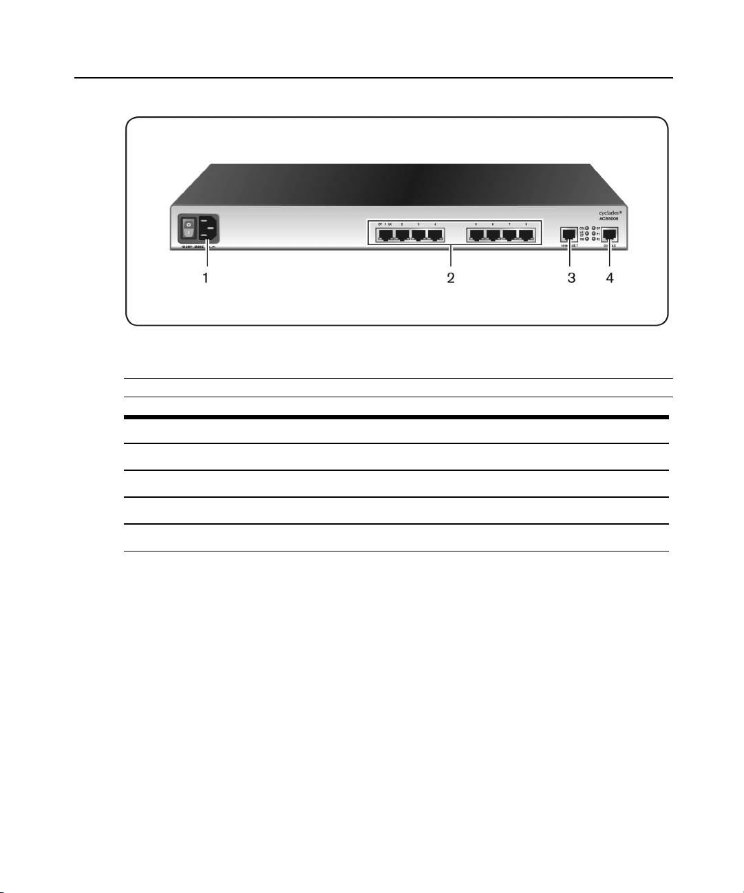
The following figure depicts the connectors on the back of a typical ACS 5000 console server.
Page 10
2 Cyclades®ACS5000 Installation/Administration/User Guide
Figure 1.2: ACS5000 Console Server Connectors
NOTE: The number of serial ports and power suppliesdepends on the model.
Table 1.1: ACS 5000 Console Server Connectors
Number Description
1
2
3
4
Power connection. This may be single or dual power. Dual power requires two power cords.
Serial port connectors.
Ethernet port connectors.
Console port connectors.
Accessing the Console Server and Connected Devices
You can access a console server and the connected servers or devices either locally or remotely
using any of the following methods.
• Web manager through LAN/WAN IP networks.
• An external modem
• Using the web manager, you can log in and launch a console session such as Telnet or
SSH to connect to the devices attached to the console server’s serial ports.
Page 11

• Connecting a server running a terminal emulation program enables an administrator to log
into the console server and either enter commands in the console server shell or use the
Command Line Interface (CLI) tool.
NOTE: Only one root or admin user can have an active CLI or web manager session. A second root or admin user
must abort the session or close the other user’s session.
CAUTION: If there are cron jobs running through automated scripts, a root or admin user login can cause the
automated cron jobs to fail.
Web Manager
Console server administrators perform most tasks through the web manager either locally or
from a remote location. The web manager runs in a browser and provides a real-time view of all
equipment connected to the console server.
The administrator can use the web manager to configure users and ports. An authorized user can
access connected devices through the web manager to troubleshoot, maintain, cycle power and
reboot connected devices.
Access the web manager using one of the following ways:
• The IP Network.
Chapter 1: Introduction 3
• A dial-in connection with an optional external modem connected to one of the serial ports.
Prerequisites for Using the Web Manager
The following conditions must be met prior to accessing the web manager.
• Basic network parameters must be defined on the console server so the web manager can be
launched over the network.
• The dynamically-assigned IP address of the console server must be known. This address is
found in one of the following three ways:
• Make an inquiry to the DHCP server on the subnet that the console server resides,
using the MAC address.
• Connect to the console server remotely using Telnet or SSH and use the ifconfig
command.
• Connect directly to the console server and use the ifconfig command through a
terminal emulator application.
Page 12

4 Cyclades®ACS5000 Installation/Administration/User Guide
• A web manager user account must be defined. The admin has an account by default, and
can add regular-user accounts to grant access to the connected servers or devices using the
webmanager.
Types of Users
The console server supports the following user account types:
• The root user who can manage the console server and its connected devices. The root user
performs the initial network configuration. Access privileges are full read/write and
management.
• Users who are in an Admin group with administrative privileges. The admin user belongs
to this group.
• Regular users who can access the connected devices through the serial ports they are
authorized for. Regular users have limited access to the web manager features.
NOTE: It is strongly recommended that you change the default password avocent for the root and admin users
before configuring the console server.
Security
The console server includes a set of security profiles that consists of predefined parameters to
control access to the console server and its serial ports. This feature provides more control over
the services that are active at any one time. As an additional security measure, all serial ports
are disabled by default, allowing the administrator to enable and assign individual ports to
users.
NOTE: The Default security profile parameters are the same as the Moderate profile.
Authentication
The console server supports a number of authentication methods to assist the administrator with
user management. Authentication can be performed locally or with a remote server, such as
RADIUS, TACACS+, LDAP or Kerberos. An authentication security fallback mechanism is
also employed should the negotiation process with the authentication server fail. In such
situations, the console server follows an alternate defined rule when the authentication server
cannot authenticate the user.
The following table lists the supported authentication methods.
Page 13

Chapter 1: Introduction 5
Table 1.2: Authentication Methods Supported
Authentication Type Definition
None No authentication.
DSView Authentication is performed with a DSView®3 server.
DSView/Local DSView management software authentication is tried first, then Local.
DSViewDownLocal Local authenticationis performed only if the DSView 3 server isdown.
Kerberos Authentication is performed using a Kerberos server.
Kerberos/Local Kerberos authentication istried first, switching to Localif unsuccessful.
KerberosDownLocal Local authenticationis performed only when the Kerberos server isdown.
LDAP Authentication is performed against an LDAP database using an LDAP server.
LDAP/Local LDAP authentication is tried first, switching to Local if unsuccessful.
LDAPDownLocal Local authenticationis performed only when the LDAP server is down.
LDAPDownLocal/Radius
Local Authentication is performed locally.For example using the /etc/passwd file.
Local/Radius Authentication is performed locallyfirst, switching to Radius if unsuccessful.
Local/TACACS+ Authentication is performed locallyfirst, switching to TACACS+ if unsuccessful.
Local/NIS Authentication is performed locallyfirst, switching to NIS ifunsuccessful.
NIS NIS authentication is performed.
NIS/Local NIS authentication is tried first, switching to Localifunsuccessful.
NISDownLocal Local authenticationis performed only when the NIS server is down.
OTP Uses the one time password (OTP) authentication method.
OTP/Local Uses the localpassword if the OTP password fails.
Radius Authentication is performed using a Radius authenticationserver.
Radius/Local Radius authentication istried first, switching to Localifunsuccessful.
RadiusDownLocal Local authenticationis performed only when the Radius server isdown.
TACACS+ Authentication is performed using a TACACS+ authentication server.
TACACS+/Local TACACS+ authentication istried first, switching to Local ifunsuccessful.
TACACS+DownLocal Local authenticationis tried only when the TACACS+ server is down.
Local authenticationis performed only when the LDAP server is down, switching to
Radius ifunsuccessful.
Page 14

6 Cyclades®ACS5000 Installation/Administration/User Guide
IPv6
The console server is compliant with IPv4, IPv6 and dual stack protocols so that you can
enable IPv4 only, IPv6 only or both protocols, with support for dial-up connections and
primary network connections. You can configure the appliance to obtain its IPv6 network
parameters from a DHCPv6 server, by static configuration (IP address, prefix length and default
gateway) or stateless auto-configuration. You can add an appliance to the local network using
either its IPv6 address or a DNS name.
Services not supporting IPv6
The following services do not support IPv6:
• NIS authentication
• NFS data logging
• Virtual ports
VPN
The console server administrator can set up VPN connections to establish an encrypted
communication between the console server and a host on a remote network. The encryption
creates a security tunnel for dedicated communications.
You can use the VPN features on the console server to create a secure connection between the
console server and every machine on the subnet at the remote location or between the console
server and a single remote host.
To set up a security gateway, install IPSec on any machine performing networking over IP,
including routers, firewall machines, application servers and end-user machines.
The ESP and AH authentication protocols are supported. RSA Public Keys and Shared Secret
are supported.
For detailed information and procedures to configure a VPN connection, see VPN Connections
on page 75.
Packet Filtering
The administrator can configure the device to filter packets like a firewall. IP filtering is
controlled by chains and rules.
Structure of IP filtering
The Firewall Configuration form in the web manager is structured on two levels:
Page 15

Chapter 1: Introduction 7
• The view table of the Firewall Configuration form containing a list of chains.
• The chains which contain the rules controlling filtering.
Chain
A chain is a named profile that includes one or more rules defining either a set of characteristics
to look for in a packet or what to do with any packet having all the defined characteristics.
The console server filter table contains a number of built-in chains, each referenced according
to the packet type they handle. As defined in the rules for the default chains, all input and
output packets and packets being forwarded are accepted.
Rule
Each chain can have one or more rules that define either the packet characteristics being filtered
or what to do when the packet matches the rule.
Each filtered packet characteristic is compared against the rules. All defined characteristics must
match. If no rules are found then the default action for that chain is applied.
Administrators can:
• Add a new chain and specify rules for that chain
• Add new rules to existing chains
• Edit a built-in chain or delete the built-in chain rules
Add rule and edit rule options
When you add or edit a rule, you can define any of the options described in the following
table.
Table 1.3: Add Rule and Edit Rule Option Definitions
Filter Options Description
With source IP, incoming packetsare filtered for the specified IP address. With destination IP,
Source IP and Mask
Destination IP and Mask
Protocol
Input Interface The input interface (eth0) used by the incoming packet.
Output Interface The output interface (eth0) used by the outgoing packet.
outgoing packetsare filtered.
If you fill in a source or destination mask, all packets are filtered for IP addressesfrom the
subnetwork in the specifiednetmask.
NOTE: For IPv6, only one field isavailable: <IP Address>/<Prefix>.
Select protocol options for filtering from ALL, Numeric, TCP, UDP, ICMP (IPv4 only) and ICMPv6
(IPv6 only).
Page 16

8 Cyclades®ACS5000 Installation/Administration/User Guide
Flag any of the above elements with Inverted to perform target action on packets not matching
any criteria specified in that line. For example, if you select DROP as the target action, specify
Inverted for a source IP address and do not specify any other criteria in the rule, any packets
arriving from any other source IP address than the one specified are dropped.
Numeric protocol options
If you select Numeric as the protocol when specifying a rule, you need to specify the desired
number.
TCP protocol options
If you select TCP as the protocol when specifying a rule, you can define the following options.
Table 1.4: TCP Protocol Option Definitions
Field/Menu option Definition
Source or Destination Port
TCP Flags
Specifya source or destination port number for filtering. Specify a range to
filter TCP packets for any port number within the range.
Specifyany of the flags: SYN (synchronize), ACK (acknowledge), FIN
(finish), RST (reset), URG (urgent), PSH (push) and one of the Any, Set, or
Unset conditions to filter TCP packetsfor the specified flag and selected
condition.
UDP protocol options
Select UDP options by selecting UDP as the protocol when selecting a rule. Choose either the
Source or Destination Port from the field, as defined above.
ICMP protocol options
When you select ICMP as a protocol when specifying a rule, you can select the ICMP options
available on the display.
Target actions
The Target is the action to be performed on an IP packet that matches all the criteria specified
in a rule.
NOTE: If the LOG and REJECT targets are selected, additionaloptions are available.
For detailed information on LOG target options, see LOG target on page 83.
For detailed information on REJECT target options, see REJECT target on page 84.
Page 17

SNMP
The administrator can activate the Simple Network Management Protocol (SNMP) agent that
resides on the console server so that the SNMP agent sends notifications about significant
events or traps to an SNMP management application. The console server SNMP agent supports
SNMP v1/v2 and v3.
For more information, see To configure SNMP: on page 78
Notifications, Alarms and Data Buffering
The administrator can set up logging, notifications and alarms to alert administrators of
problems. System generated messages on the console server and the connected servers or
devices can be sent to syslog servers for handling. The administrator can also configure data
buffering to store data from communication on serial ports for monitoring.
Data from communication with serial-connected consoles can be stored locally in the console
server’s flash memory or remotely either on an NFS server or a syslog server.
Syslog servers
Messages about the console server and connected servers or devices can be sent to central
logging servers, called syslog servers. Console data from devices connected to serial ports can
be stored in data buffer files on syslog servers. By default, logging and data buffering are not
enabled.
Chapter 1: Introduction 9
Prerequisites for logging to syslog servers
Before configuring syslogging, ensure the syslog server is pre-configured with a public IP
address and is accessible from the console server. The system administrator must obtain both the
IP address of the syslog server from the syslog server’s administrator and the facility number for
messages from the console server. Facility numbers are used on the syslog server for handling
messages generated by multiple devices.
Facility numbers for syslog messages
Each syslog server has seven local facility numbers available for its administrator to assign to
different devices or groups of devices, at different locations. The available facility numbers are
local0 through local7.
Example of using facility numbers
The syslog system administrator sets up a server called syslogger to handle log messages from
two console servers. One console server is located in São Paulo, Brazil and the other in
Fremont, California. The syslog server’s administrator wishes to aggregate messages from the
Page 18

10 Cyclades®ACS5000 Installation/Administration/User Guide
São Paulo console server into the local1 facility and to aggregate messages from Fremont
console server into the local2 facility.
On syslogger the system administrator has configured the system logging utility to write
messages from the local1 facility to the /var/log/saopaulo-config file and the messages from the
local2 facility to the /var/log/fremont-config file. If you were in Fremont and identifying the
syslog server using the web manager, according to this example, you would select the facility
number local2 from the Facility Number pull-down menu on the Syslog form.
Managing Users of Connected Devices
This section provides a list of tasks that a console server administrator can perform to enable
access to connected devices.
Configuring access to connected devices
During hardware installation of the console server, the installer connects the servers, devices
and any IPDUs to the serial ports. During software configuration, the console server
administrator performs the common tasks listed in the following table.
Table 1.5: Common Administrator Tasks for Configuring Software
Task Where Documented
To Configure a Serial Port Connection Protocol for a Console Connection
To Configure User Accessto Serial Ports
Console Server and Power Management
Authorized users can turn on, turn off and reboot (turn off and turn on) devices that are plugged
into one of the following types of power devices, which can be optionally connected to any of
the serial ports:
• Avocent PM Power Distribution Units (PM PDUs) - With Avocent PM PDUs, up to 128
PDU outlets can be daisy-chained from a single serial port.
• Cyclades PM Intelligent Power Distribution Units (IPDUs) - With Cyclades PM IPDUs, up
to 128 IPDU outlets can be daisy-chained from a single serial port.
• Avocent SPC power control devices.
To configure a serial por t
connection protocol for a console
connection: on page 107
To configure user accessto serial
ports: on page 112
Page 19

Chapter 1: Introduction 11
• Server Technology Sentry™ family of Switched Cabinet Power Distribution Units (CDUs)
and switched CDU Expansion Module (CW/CX) power devices.
• Server Technology Sentry Power Tower XL™ (PTXL) and Power Tower Expansion
Module (PTXM) power devices.
• Server Technology Sentry Smart CDU (CS) and smart CDU Expansion Module power
devices with version 6.0g or later.
NOTE: The term PDU is used to refer to any of these types of power devices.
The console server automatically recognizes and supports a Cyclades PM IPDU or Avocent
SPC device when the serial port to which the power device is connected has been configured
for power management.
Additional requirements for Server Technology IPDUs
For supported Server Technology IPDUs the following additional requirements apply:
• The console server must be managed by a DSView 3 server (DSView 3 software version
3.4.1 or above).
• The needed power device license must be present, and the power device must be added to
the DSView 3 software.
The license is automatically downloaded from the DSView 3 server onto the console server.
Configuration and management can then be performed either through the DSView 3 software or
through the web manager.
Conventions used to identify outlets
Several formats (such as outlet names, outlet groups, IPDU IDs and port names) can be used to
identify outlets during configuration, as described below:
• An administrator can configure optional names for each outlet to replace the default names
assigned by the system. Outlet names must begin with a letter. Valid characters are letters,
numbers, dash (-) and underscore (_). When an outlet name is configured, the name can be
used in other power management configurations.
• An administrator can configure outlet groups. Once defined, outlet groups are specified
with the dollar sign ($) prefix followed by the outlet group name: $outlet_groupname. For
example, $Cyclades_IPDU specifies an outlets group called Cyclades_IPDU.
• An administrator can specify outlets in any of the following ways:
• With a name that was configured for the outlet
• With an outlet group name preceded by the $ suffix
Page 20

12 Cyclades®ACS5000 Installation/Administration/User Guide
• With the IPDU ID assigned to the IPDU
• With the port number to which the IPDU is connected
The IPDU and port number are always followed by one or more outlet numbers in
brackets: [outlets]. Commas between outlet numbers indicate multiple outlets. Hyphens
indicate a range. For example, [1,5-8] specifies outlets 1, 5, 6, 7 and 8.
• IPDU ID - An IPDU ID is automatically assigned to each IPDU when the port to which it
is connected is configured for power management. An administrator can optionally assign a
name to each IPDU. Both automatically assigned and administrator-assigned names are
referred to as IPDU IDs.
• Specify outlets with the IPDU ID in the following format: IPDU_ID[outlets]. For
example, ilA[4,5] specifies outlets 4 and 5 on an IPDU whose ID is ilA.
• When devices are plugged into more than one IPDU, you can separate multiple IPDU
entries with commas in the form IPDU_ID[outlets],IPDU_ID[outlets]. For example,
i1A[1,5],i1B[2] specifies two outlets on IPDU i1A and one outlet on a daisy-chained
IPDU whose IPDU ID is ilB.
• Port number - To specify outlets by the port number to which the IPDU is connected, use
the suffix !ttyS followed by the port number followed by [outlets]. For example, !ttyS2[16]
indicates outlet 16 on an IPDU that is connected to serial port 2.
You can specify outlets in a chain of IPDUs with the port ID two different ways:
• By the outlet sequence. For example, in !ttyS3[2,16], outlet number 2 is the second
outlet on the first IPDU in a chain that is connected to port 3. If the first IPDU has 10
outlets, outlet number 16 would be the sixth outlet on the second IPDU.
• By IPDU sequence, identified with alphabetic characters. The first IPDU is A and the
second is B and so forth. Precede the character with a hyphen. For example, !ttyS3-B[6]
would also refer to the sixth outlet on the second IPDU in the chain connected to port
3.
Configuring power management
Administrators commonly perform power management through the web manager to assign
power management permissions to users, configure IPMI devices and configure ports for power
management.
Configuring ports for power management by authorized users
Administrators of connected devices who have power management permissions can do power
management while connected by using a hotkey that brings up a power management screen.
Page 21

For IPMI power management, the default hotkey is Ctrl+Shift+I. For IPDU power management,
the default hotkey is Ctrl+p.
Options for managing power
Authorized users can perform power management through the console server by using forms in
the web manager, from a power management screen while logged into a device or from the
command line while logged into the console server.
An authorized user with administrative privileges can perform IPDU and IPMI power
management. A regular user with permissions to the connected devices can perform IPDU
power management.
Power management through the web manager
Users with power management permissions can perform power management through the web
manager. The web manager menu includes two power management options, both discussed in
Chapter 6.
Power management from the console server command line interface (CLI)
Console server administrators can use the ipmitool command to manage power on IPMI devices
while logged into the console server with administrative rights. The ipmitool command is
documented in the Cyclades ACS 5000 Command Reference Guide.
Chapter 1: Introduction 13
Hostname Discovery
An administrator can configure hostname discovery on the console server. When hostname
discovery is enabled for a serial port, the console server attempts to discover the hostname of
the server connected to the port. If the hostname of a server is successfully discovered, the
hostname of the device connected to it is shown as the serial port alias.
If the server is later moved to another port, and the new port is also configured for hostname
discovery, the hostname for the server is again discovered at the new serial port.
NOTE: If the console server isbeing managed through DSView 3 software, hostname discovery can be configured
through the DSView 3 software.
An administrator can also configure site-specific probe and answer strings. These strings are
used to probe the target device that is connected to the selected serial port and extract the
hostname from the answer that is received in response to the probe string. The result of each
probe string is matched against all answer strings. If no match is found, the next probe string is
sent until there are no more probe strings or a match occurs. The default strings have a broad
range and work in most cases.
Page 22

14 Cyclades®ACS5000 Installation/Administration/User Guide
NOTE: Probe string configuration requires knowledge of C-style escape sequences. Answer strings require
knowledge of POSIXextended regular expressions. Hostnames longer than 31 characters are truncated when the
hostname isassigned to the serial port alias.
Page 23

Installation
2
Important Pre-installation Requirements
Before installing and configuring the console server, ensure you have the following:
• Root Access on your local UNIX machine to use the serial ports.
• An appropriate terminal application for your operating system.
• IP address, DNS, Network Mask and Gateway addresses of your server or terminal, the
console server and the machine to which the console server is connected.
• A internet browser that supports the console server web manager.
15
• Java 2 Runtime Environment (JRE)version 1.4.2 or later.
Basic Installation Procedures
Mounting the console server
You can mount the console server on a wall, rack or cabinet or place it on a desktop or other flat
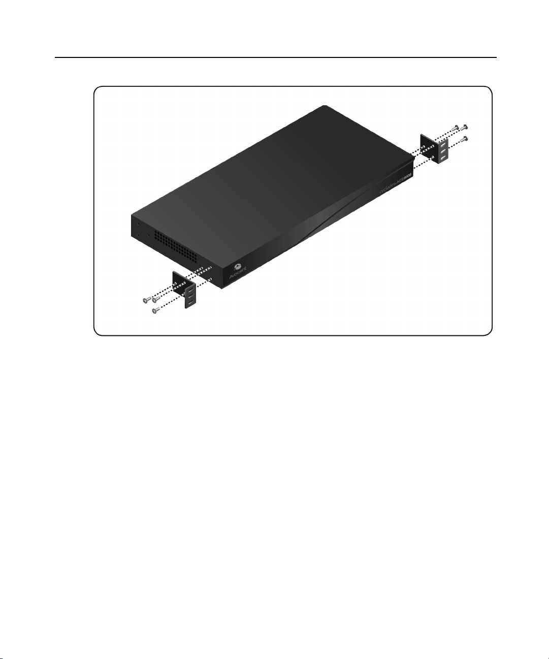
surface. Two brackets are supplied with six hex screws for attaching the brackets to the console
server for mounting.
Page 24
16 Cyclades®ACS5000 Installation/Administration/User Guide
Figure 2.1: Placement of Mounting Brackets
To rack mount the console server:
1. Install the brackets on to the front or back edges of the console server using a screwdriver
and the screws provided with the mounting kit.
2. Mount the console server in a secure position.
Making an Ethernet connection
Connect a CAT5 patch cable from the console server port labeled 10/100Base-T to an Ethernet
hub or switch.
To connect devices to serial ports:
Using patch cables with RJ-45 connectors and DB-9 console adaptors assemble crossover
cables to connect the console server serial ports to the device’s console port.
Page 25

Chapter 2: Installation 17
Making a direct connection to configure the network parameters.
On your Microsoft® Windows workstation, ensure that a terminal emulation program is
installed. On servers running a UNIX-based operating system such as Solaris or Linux, make
sure that a compatible terminal emulator such as Kermit or Minicom is installed.
To connect to the console port:
You can use a CAT 5 straight-through cable with RJ-45 connectors and the appropriate adaptor
provided in the product box to assemble a console cable. All adaptors have an RJ-45 connector
on one end and either a DB25 or DB9 male or female connector on the other end.
1. Connect the RJ-45 end of the cable to the port labeled Console on the console server.
2. Connect the adaptor end of the cable to the console port of your server or device.
3. Open your terminal emulation program, start a connection session, select an available COM
port and enter the following console parameters.
• Bits per second: 9600 bps
• Data bits: 8
• Parity: None
• Stop bit: 1
• Flow control: None
Console server serial port pin-out information
The following table provides the serial port pin-out information for the consoleserver.
Table 2.1: ACS5000 Console Server Serial Port Pin-out
Pin No. Signal Name Input/Output
1 RTS OUT
2 DTR OUT
3 TxD OUT
4 GND N/A
5 CTS IN
6 RxD IN
7 DCD IN
8 DSR IN
Page 26

18 Cyclades®ACS5000 Installation/Administration/User Guide
Turning on the console server and the connected devices
Perform the following procedures in the order shown to avoid problems with components on
connected devices.
To turn on the console server:
1. Make sure the console server’s power switch is off.
2. Plug in the power cable.
3. Turn the console server’s power switch(es) on.
NOTE: If your console server isequipped with dual-power supplies, make sure you turn both power switches on.
After system initialization, a beep sound may warn if one of the power supplies is off.
To turn on connected devices:
Turn on the power switches of the connected devices only after you have completed the
physical connection to the console server.
Performing basic network configuration using the wiz command
The following procedure assumes that a hardware connection is made between the console
server’s console port and the COM port of a server.
To log into the console server through the console:
From your terminal emulation application, log into the console port as ro ot.
ACS 5000 console server login: root
Password: avocent
WARNING: For security reasons, it is recommended that you change the default password for root (avocent) and
admin (avocent) as soon aspossible. To change the default password of a root user, enter the passwd command
at the prompt and enter a new password when prompted. To change the default password of an admin user, enter
passwd admin at the prompt and enter a new password when prompted.
NOTE: The Security Advisory appears the first time the console server is accessed or after a reset to factory default
parameters. If you are upgrading the firmware on the console server, the previously configured security
parameters are retained in the Flash memory.
To use the wiz command to configure network parameters:
1. Launch the configuration wizard by entering the wiz command.
[root@CAS root]# wiz
As shown below, the system displays the configuration wizard banner and begins
running the wizard.
Page 27

Chapter 2: Installation 19
***********************************************************
********* C O N F I G U R A T I O N W I Z A R D *********
***********************************************************
INSTRUCTIONS for using the Wizard:
You can:
1) Enter the appropriate information for your system
and press ENTER or
2) Press ENTER if you are satisfied with the value
within the brackets [ ] and want to go on to the
next parameter or
3) Press ESC if you want to exit.
NOTE: For some parameters, if there is nothing within
the brackets, it will continue to ask for a value.
In that case, you must enter a valid value or # if you
do not wish to configure the value.
Press ENTER to continue...
2. At the prompt, press Enter to view the default settings.
3. At the prompt, enter n to change the defaults.
Set to defaults (y/n)[n]: n
4. Press Enter to accept the default hostname, or enter your own hostname and then press
Enter.
Hostname [CAS]: <hostname server name>
5. The IP version Configuration form is displayed. Select the IP version you wish to run and
press Enter. Choices are IPv4 enabled (0), IPv6 enabled (1) or Dual Stack (2).
NOTE: Depending on which IP configuration you choose, the wizard will direct you to the appropriate form.
To configure for IPv4 protocol:
1. If you have typed 0 or 2 for IP version configuration, the IPv4 Configuration form will
appear and give you the choice to use DHCP to assign an IP address for your system.
Default is Y.
2. Press Enter to keep DHCP enabled or type n to specify a static IP address for the console
server. By default, the console server uses the IP address provided by the DHCP server. If
your network does not use DHCP, the console server will default to 192.168.160.10.
Do you want to use DHCP to automatically assign an IP for your system?
(y/n)[y] :
Page 28

20 Cyclades®ACS5000 Installation/Administration/User Guide
NOTE: If you choose to use DHCP and have selected IPv4 enabled (option 0), the IPv4 Current Configuration
verification screen will be displayed as shown below.
***************************************************************
*********** C O N F I G U R A T I O N W I Z A R D ***********
***************************************************************
Current configuration:
Hostname : Rogreto
Domain name : corp.company.com
Primary DNS Server : 172.26.29.4
Second DNS Server : #
IPv4 Configuration:
DHCP : enabled
IPv6 Configuration: Disable
Are all these parameters correct? (y/n) [n] :
3. Verify that the configuration is correct and press Enter. You will be prompted to activate
the configuration settings.
4. If you typed n to change the default static IP address, enter a valid IPv4 system address.
System IP[192.168.160.10]: <ACS_5000_console_server_IP_address>
5. Press Enter. Enter the IP address for the gateway.
Gateway IP[eth0] : <gateway_IP_address>
6. Press Enter. Enter the netmask for the subnetwork.
Network Mask[#] : <netmask>
7. Press Enter.
NOTE: If you have selected IPv4 enabled and have set the static IP, gateway and netmask addresses, the IPv4
Current Configuration verification screen willbe displayed. Check all parameters and press Enter. You willbe
prompted to activate the configuration settings.
To configure for IPv6 protocol:
1. If you entered option 1 or 2 for IP version configuration, the IPv6 Configuration Method
form will be displayed.
2. Choices for IPv6 configuration are Stateless Only (0), Static (1) or DHCP (2). The default is
Stateless Only. Type the number corresponding to your choice and press Enter. The choice
you enter selects the method used to assign the IPv6 system address.
Page 29

Chapter 2: Installation 21
• Stateless Only: The router will multicast the IPv6 prefix along with the console
server’s MAC address, then listen for the other devices on the local network to allow
the router to assign the IPv6 address.
• Static: You must manually assign a unique IPv6 address for the console server.
• DHCP: The router will request the IPv6 address from the DHCPv6 server.
3. The DHCPv6 options form is displayed. Choices are None (0), DNS (1), Domain (2) and
DNS and Domain (3). Type the number corresponding to your choice and press Enter.
• From None (0): Enter your domain name.
• From Domain (1): Enter your domain name.
• From DNS (2): Follow the on-screen instructions.
• From DNS (3): The Current Configuration screen is displayed.
4. If None (0) or Domain (1), enter your domain name.
Domain name[corp.avocent.com] :
5. Enter the IPv4 or IPv6 address for the Primary DNS (domain name) server.
Primary DNS Server[172.26.29.4] : <DNS_server_IPv4_or_IPv6_address>
6. Press Enter. The Current Configurations screen appears. If correct, enter y after the prompts
shown in the following screen example.
Are all these parameters correct? (y/n)[n]: y
Do you want to activate your configurations now? (y/n)[y]: y
Do you want to save your configuration to Flash? (y/n)[n]: y
7. To confirm the configuration, enter the ifconfig command.
8. After the initial configuration, proceed to the web manager to select a security profile as
described in the following section.
NOTE: To use the web manager, obtain your console server’s IP address. The console server may be set up with a
staticIP address at your site. By default, the console server uses the IP address provided by the DHCP server. If
your network does not use DHCP, then the console server defaults to192.168.160.10.
Selecting a security profile using the web manager
After the initial configuration, connect to the web manager by entering the IP address of the
console server in a supported browser.
NOTE: Once you log in to the web manager, a securityprofile must be selected to further configure the console
server using the web manager. For this reason your browser redirects to Wizard - Step1: Security Profiles.
Page 30

22 Cyclades®ACS5000 Installation/Administration/User Guide
Selecting a security profile
Select a pre-defined security profile or define a custom profile for specific services. The profiles
are:
• Secured - Disables all protocols except sshv2, HTTPS and SSH to serial ports.
• Moderate - Enables sshv1, sshv2, HTTP, HTTPS, Telnet, SSH and Raw connections to
serial ports, ICMP and HTTP redirection to HTTPS.
• Open - Enables Telnet, sshv1, sshv2, HTTP, HTTPS, SNMP, RPC, ICMP, SSH and Raw
connections to serial ports.
• Default - Sets the profile to the same configuration as Moderate profile.
• Custom - Allows custom configuration of individual protocols and services.
For detailed information on security profiles, see Security Profiles on page 98.
The administrator can perform the following tasks using the web manager.
• Administer the console server and its connected devices.
• Configure user and group permissions.
• Access the serial ports and the connected devices.
Adding users and configuring ports using the web manager
NOTE: From the factory, the console server is configured with all serial ports disabled.
The administrator can add users, enable or disable the serial ports and select and assign specific
users to individual ports. For more information on managing users and ports, see Security Menu
and Forms on page 89 and Ports Menu and Forms on page 103
Other Methods of Accessing the Web Manager
You can access the web manager using either DHCP or the default IP address.
NOTE: Accessing the web manager using either DHCP or the default IP address requires additional setup and
configuration specificto your site’snetwork configuration.
To use a dynamic IP address to access the webmanager:
This procedure assumes that DHCP is enabled and that you are able to obtain the dynamic IP
address currently assigned to the console server.
1. Mount the console server.
2. Connect servers and other devices to be managed through the console server.
Page 31

3. Turn on the console server and connected devices.
4. Enter the console server’s IP address in the browser’s address field.
5. Log in to the console server and finish configuring users and other settings using the web
manager.
To use the default IP address to access the web manager:
The default IP address for the console server is 192.168.160.10. This procedure assumes that
you are able to temporarily change the IP address of a server located on the same subnet as the
console server.
1. On a server that resides on the same subnet as the console server, change the network
portion of the IP address of that server to 192.168.160. For the host portion of the IP
address, you can use any number except 10, 0 or 255.
2. Open a browser on the server with the changed address. Enter the console server’s default
IP address, http://192.168.160.10, to bring up the web manager and log in.
Connecting PDUs
You can connect Avocent PM PDUs and Cyclades PM IPDUs to the serial ports on the console
server using an RJ-45 to RJ-45 UTP cable. Avocent PM PDUs and Cyclades IPDUs include
two RS-232 outlets for serial management and daisy-chaining. Any combination of Avocent
PM PDUs and/or Cyclades IPDUs up to 128 outlets can be daisy-chained into a single virtual
power distribution unit.
Chapter 2: Installation 23
The daisy chain can include Avocent PM PDUs and Cyclades IPDUS with the following
restrictions:
• Avocent PM PDUs should be the first in the daisy chain.
• All Cyclades IPDUs should have firmware version 1.9.2 or later.
Connecting third-party IPDUs
IPDUs from SPC and ServerTech can be connected to and managed by the console server.
Special cabling and an adaptor is required for this purpose. These cables and adaptors are
available from Avocent, or you can build your own cable as needed. See Console server serial
port pin-out information on page 17 for this purpose.
NOTE: ServerTech IPDU installation, management and operation islicense-based through Avocent’sDSView® 3
management software only.
Page 32

24 Cyclades®ACS5000 Installation/Administration/User Guide
To daisy-chain PDUs to the console server:
This procedure assumes that you have one Avocent PM PDU or Cyclades IPDU connected to a
serial port on the console server.
NOTE: Daisy-chaining is not possible with SPC power control devices. ServerTech PDUs will allow only one level
(Master and Slave) of daisychaining.
1. Connect one end of a UTP cable with RJ-45 connectors to the OUT port of the PDU
connected to the serial port on the console server.
2. Connect the other end of the cable to the IN port of the next PDU.
3. Repeat steps 1 and 2 until you have connected the desired number of PDUs. Only one
additional level is allowed with ServerTech PDUs.
Contact Avocent Technical Support for more information on:
• Installing SPC devices and ServerTech PDUs
• Replacing an Avocent CCM console management appliance with a console server
• Cabling requirements for using the console server with SPC devices and ServerTech PDUs
Page 33

Web Manager for Regular Users
3
Using the Web Manager
Console server users perform most tasks through the web manager. The web manager runs in a
browser and provides a real-time view of all equipment connected to the console server.
Authorized users can access devices connected to serial ports:
• If a device console is connected, the user can access the console of the target device.
• If a terminal is connected, the user can connect from the terminal to the console server and
access other servers.
• If a modem is connected, a user can dial in and access the console server and connected
devices.
25
• If an IPDU is connected, a user can manage power for devices connected to the outlets of the
IPDU.
To log into the web manager:
1. Type the console server’s IP address in your browser’s address field.
NOTE: Refer to Chapter 2 for requirements to start the web manager.
2. Press Enter. The web manager Login form is displayed.
3. Enter your username and password.
Features of Regular User Forms
The following figure shows features of the web manager when a regular user logs in.
Page 34

26 Cyclades®ACS5000 Installation/Administration/User Guide
Figure 3.1: Regular User Form
NOTE: The form area changes according to which menu option isselected.
Table 3.1: Description of Regular User Web Interface
Number Description
1 Form area.
Console server information area and logout button. This area contains the following information:
logout button - Press logout to exit the current session. The login screen is displayed.
2
3
Host Name - Displaysthe console server’s hostname selected by the administrator.
IP Address - Displays the console server’s current IP address.
Model - The model number of the console server.
Side navigationmenu. Select one of the options to change the content in the form area. For regular
users, the choices are Connect, IPDU Power Mgmt. and Security.
Page 35

Connect
When you select the Connect option, the form displayed will allow you to connect to the
console server or its serial ports.
Permission to access a port or perform power management is granted by the administrator when
your user account is created.
Connect to the console server
When you click the Connect to ACS 5000 radio button on the Connect form, a Java applet
viewer appears running an SSH session on the console server. A Java applet displays when you
connect to the console server. The IP address of the console server is followed by the session
type.
The following table describes the available buttons in the Java applet:
Table 3.2: Java Applet Buttons
Button Purpose
SendBreak To send a break to the terminal
Disconnect To disconnect from the Java applet
Chapter 3: Web Manager for Regular Users 27
Select the left icon to reconnect to the server or device; or select the right
icon to end the session and disconnect from the Java applet.
Connect to serial ports
The list of serial ports includes the port names or administrator-defined aliases only for the ports
you have permission to access.
Port access requirements
When you connect to a serial port to access a server or another device, access rights to the
specific serial port on the console server is required.
NOTE: If an authentication server is set up in your network, an authentication method and the related parameters
should be set up to allow access to the connected devices.
When you select a port from the serial pull-down list and click the Connect button, a Java
applet viewer appears. The Connected to message in a gray area at the top of the screen shows
the IP address of the console server followed by the TCP port number.
Page 36

28 Cyclades®ACS5000 Installation/Administration/User Guide
Connection protocols for serial ports
You can access a server or a device connected to a serial port by using the connection protocol
specified for the port. The following table shows the protocols available for the serialports.
Table 3.3: Available Serial Port Protocols
Connection Type Protocol
Console AccessServer (CAS) Telnet, ssh, Telnet&ssh, Raw
Terminal Server (TS) Telnet, sshv1, sshv2, Local Terminal, Raw Socket
Dial-up PPP-No Auth., PPP, SLIP, CSLIP
Other Power Management, Bi-directional Telnet
TCP port numbers for serial ports
The TCP port numbers by default start at 7001 for serial port 1 and increment up to the number
of serial ports on your console server. The console server administrator may change the default
port numbers if needed.
To use Telnet to connect to a device through a serial port:
For this procedure you need the hostname of the console server or its IP address and the TCP
port number for the serial port to which the device is connected.
• To use Telnet in a shell, enter the following command:
telnet <hostname | IP_address> TCP_port_number
To close a Telnet session:
Enter the Telnet hotkey defined for the client. The default is Ctrl and q to quit.
To use SSH to connect to a device through a serial port:
For this procedure, you need the username configured to access the serial port, the TCP port
number and the hostname of the console server or its IP address.
• To use SSH in a shell, enter the following command:
SSH - # ssh -l username:TCP_port_number <console_server_IP_address|or
the hostname>
To close an SSH session:
Enter the hotkey defined for the SSH client followed by a period. The default is ~.
NOTE: Make sure you enter the escape character followed by a period at the beginning of a line to close the SSH
session.
Page 37

IPDU Power Management
IPDU management allows you to manage the power outlets on power management appliance
products. If you have permission to manage outlets on a power management appliance,
selecting the IPDU Power Mgmt. option will display a form with two tabs, Outlets Manager
and View IPDUs Info.
Access the forms under IPDU Power Mgmt. menu to manage outlets or view IPDUinformation.
Outlets Manager
When you select IPDU Power Mgmt. - Outlets Manager, an error message appears either if you
do not have permission to manage power on any of the IPDU outlets or the console server
cannot detect an IPDU that has been configured for power management.
If you have permission to manage power on one or more outlets of the power management
appliance, the Outlets Manager form is displayed.
The form shows separate entries for each serial port configured for power management, a name
for the configured serial port if one is defined by the administrator and the number of IPDUs
connected. The matrix displays a line item for each outlet you are authorized to manage.
The authorized user can perform the following for any listed outlet:
Chapter 3: Web Manager for Regular Users 29
• Edit the outlet name. Enter a name to identify the server or device plugged into the outlet.
• Cycle. Turn power briefly off and on again.
• Turn the power On/Off to the outlet.
• Lock or unlock the outlet to prevent accidental changes to the power state (available for
Avocent PM PDUs and for Cyclades IPDUs).
• Edit the post-on delay. The post-on delay is the time interval (in seconds) the system waits
between turning on the currently-selected outlet and the next outlet. The default is set at
0.5 seconds (available for Avocent PM PDUs, Cyclades IPDUs and ServerTech PDUs).
• Edit minimum on time and minimum off time. This is the minimum time the outlet should
be on or off before changing the state to off or on (available for Avocent SPC devices).
• Edit the wake state. The wake state is the outlet state when the PDU is turned on
(available for Avocent SPC devices and for ServerTech PDUs).
• Edit post-off delay. The post-off delay is the delay (in seconds) the system waits between
turning off the currently-selected outlet and the next outlet (available for some models of
Avocent PM PDUs).
Page 38

30 Cyclades®ACS5000 Installation/Administration/User Guide
• Edit current thresholds - high critical, high warning, low warning and low critical
(available for some models of Avocent PM PDUs).
The following table describes the corresponding buttons to perform the previous operations.
Table 3.4: Regular User - Outlet Management Buttons
Button or icon Purpose
Edit Lets you edit an outlet name and the turn-on interval.
Cycle Turn power briefly off and then on again.
Bulb
Lighted (yellow)
Unlit (gray) bulb
Padlock
Locked
Unlocked
Outlets Group Ctrl
Select IPDU Power Mgmt. - Outlet Groups Ctrl to display the Group Name Outlets page.
If a user has been authorized to control specific outlet groups assigned by an administrator, any
group names are displayed under Group Name Outlets. In this mode, the user can turn on, turn
off, lock, or cycle the outlets in the group all at once using the controls under Group Ctrl (Ipdu
and Ports).
NOTE: The Lock button can onlybe used with Avocent PM PDUs and CycladesIPDUs.
View IPDU info
Select IPDU Power Mgmt. - View IPDUs Info to display the Power Management Information
page.
The following information is displayed for each port configured for power management.
Table 3.5: Power Management Display Information by Detected IPDU
Form Heading Description Example
Power is on. Click to turn power off to that outlet.
Turn power off.
Outlet is locked. Click to unlock the outlet.
Outlet is unlocked. Click to lock the outlet.
ID Either a default name or administrator-configured ID. i1A
Page 39

Chapter 3: Web Manager for Regular Users 31
Form Heading Description Example
Model IPDU model number.
Number of Outlets IPDU number of outlets. 20
Number of Banks IPDU number of banks/circuits. 2
Single-Phase/3-Phase IPDU number of phases. Single-Phase
Software Version IPDU firmware version. 1.9.2
PDU Current IPDU current levelin amperes. 0.0
PDU Voltage The nominal input voltage feeding the power device in volts. 210
PDU Power
Consumption
PDU Power Factor
IPDU power consumption in watts. 0.0
The ratio of the real power to the apparent power; a number
between 0 and 1 that is frequently expressed as a percentage.
Real power is the capacity of the circuit for performing work in a
particular time. Apparent power is the product of the current and
voltage of the circuit.
Avocent Cyclades
PM20i/30A PDU
1.0
Bank Information
Bank (Name) Name of the bank. A
Current Bank current levelin amperes. 0.0
Voltage Bank voltage in volts. 119 V
Power Consumption Bank power consumption in watts. 0.0 A
Power Factor Bank power factor. 0.00
Phase Information
Phase (Name) Name of the phase. N/A
Current Phase current levelin amperes. N/A
Voltage Phase voltage in volts. N/A
Power Consumption Phase power consumption in watts. N/A
Power Factor Phase power factor. N/A
Environmental Sensors Information
Page 40

32 Cyclades®ACS5000 Installation/Administration/User Guide
Form Heading Description Example
Type (Name) Type of the sensor.
Current information displays the actual alarm state of the current level based on the configured
thresholds when available. The alarm state can have one of the following values:
Voltage, Power Factor and Power Consumption display either the Estimated or Measured value.
NOTE: Some power devicesdo not have the capability to read the real input voltage/power factor using proper
voltage/power factor sensors; in thiscase the values are configurable.
When recorded maximum value is provided by the PDU, it is shown in the same row of the
actual value.
Security
TemperatureInternal
• Tripped - when hardware overcurrent protection is tripped
• High Critical - when the value is greater than the high critical threshold
• High Warning - when the value is greater than the high warning threshold and less
than the high critical threshold
• Low Warning - when the value is greater than the low critical threshold and less than
the low warning threshold
• Low Critical - when the value is less than the low critical threshold
Use the following procedure to set or change your password.
To change your password:
1. Select the Security option from the menu panel.
2. Enter your current password in the Current Password field.
3. Enter the new password in the New Password and the Repeat New Password fields.
4. Click OK.
5. Log out and log in using your new password to verify your password change.
Page 41

Web Manager for Administrators
4
This chapter is for system administrators who use the web manager to configure the console
server and its users. For information on how to configure the console server using vi or Command
Line Interface (CLI), please consult the Cyclades ACS 5000 Command Reference Guide.
The console server’s web manager for administrators describes two modes of operation, Wizard
and Expert.
This section provides an overview of the web manager forms. Subsequent sections describe the
menus, forms and the configuration procedures of the web manager in Wizard and Expert modes.
If you are a regular user, see Web Manager for Regular Users on page 25.
Common Features of Administrator Forms
33
The following figure shows the control buttons displayed at the bottom of the form when logged
into the web manager as an administrator.
Figure 4.1: Administrator - Web Manager Buttons
The following table describes the uses for each control button.
Table 4.1: Description of Administrator Web Manager Buttons
Button name Use
back Onlyappears in Wizard mode. Returns the previousform.
try changes Tests the changes entered on the current form without saving them.
cancelchanges Cancels all unsaved changes.
apply changes Appliesand savesall unsaved changes.
Page 42

34 Cyclades®ACS5000 Installation/Administration/User Guide
Button name Use
reload page Reloads the page.
Help Displaysthe online help.
next Onlyappears in Wizard mode. Goes to the next form.
The unsaved changes button appears on the lower right hand corner of the web
unsaved changes
manager and a graphical LED blinksred whenever the current user has made
any changesand has not yet saved the changes.
no unsaved changes
The no unsaved changes button appears and a graphical LED appears in green
when no changes have been made that need to be saved.
The various web manager actions for trying, saving and restoring configuration changes are
summarized in the following table.
Table 4.2: Administrator - Options for Trying, Saving and Restoring ConfigurationChange
Task Action Result
Updates the appropriate configuration files. Changes are
preserved if you log in and log out and even if you restart the
try changes Click the try changes button
cancelchanges
apply changes Clickthe apply changes button
Clickthe cancelchanges
button
system. Changes stay in effect unlessthe cancelchanges
button is clicked. The changes can be restored at any time
until the apply changes button is clicked.
Restores the configuration files fr om the backup that was
created the last time changes were applied.
If try changes has not been previouslyclicked, updates the
appropriate configuration files. Overwrites the backedup
copy of the configuration files.
The following table illustrates the information that displays in the upper right corner of all web
manager forms.
Table 4.3: Administrator - Logout Button and Other Information in the Upper Right
Form Area Button and
Information
Purpose
logout Clickthis button to log out.
Host Name: Cyclades
IP Address: 192.168.48.11
Model: ACS5016
Displays the hostname, IP address assigned during initial configuration
and the model number of the console server.
Page 43

Logging Into the Web Manager
The following procedure describes the login process to the web manager and what should be
expected the first time you log in to the console server.
To log into the web manager:
1. Enter the IP address of the console server in the address field of your browser.
NOTE: The console server is usually assigned a static IP address. If DHCP is enabled, you must find out the
dynamically-assigned IP address each time you need to run the web manager. If necessary, use the default staticIP
address 192.168.160.10 pre-configured in the consoleserver.
a. If DHCP is disabled, use the static IP address assigned by the administrator.
b. If DHCP is enabled, enter the dynamically-assigned IP address. The Login page
displays.
2. Log in as root and type in the root password. The default password is avocent.
CAUTION: It isimportant to change the root and admin password as soon as possible to avoid security breaches.
If another administrator is already logged in, a dialog box will prompt you to log off the other
administrator before logging in.
Chapter 4: Web Manager for Administrators 35
3. Select Yes or No and then click Apply.
NOTE: Be sure to read the securityadvisory message that appears on the screen. Your pop-up blocker must be
disabledfor the security advisory to appear.
Overview of Administrative Modes
The web manager operates in one of two modes, Wizard or Expert.
NOTE: If you selectWizard, the mode button will read Expert. If you select Expert, the mode button willread
Wizard.
Wizard mode
The Wizard mode is designed to simplify the setup and configuration process by guiding the
administrator through six configuration steps.
When you log in to the console server as an administrator or as a user with administrative
privileges, by default the system point to Expert Mode-Ports-Ports Status form.
The following is a typical form of the web interface in Wizard Mode. The user entry form
varies depending on the selected menu item.
Page 44

36 Cyclades®ACS5000 Installation/Administration/User Guide
Figure 4.2: Example of Web Manager Form in Wizard Mode
Expert mode
Expert is the default mode when logging in to the console server. The following is a typical
console server screen in Expert mode. The main difference in the interface when you switch
between the two modes is the addition of a top menu bar in the Expert mode to support more
detailed and customized configuration.
In Expert mode the top menu bar contains the primary commands and the left menu panel
contains the secondary commands. Based on what you select from the top menu bar, the left
menu selections will change accordingly. Occasionally, an Expert mode menu selection has
multiple forms identified by tabs as shown in Figure 4.3.
Page 45

Chapter 4: Web Manager for Administrators 37
Figure 4.3: Example of Web Manager Form in Expert Mode
Page 46

38 Cyclades®ACS5000 Installation/Administration/User Guide
Page 47

Configuring the Console Server in
39
5
Wizard Mode
Step 1: Security Profile
A security profile consists of a set of parameters that can be configured in order to have more
control over the services active at any time.
Pre-defined security profiles
There are three pre-defined security profiles:
• Secure - Authentication to access serial ports is required and SSH root access is not allowed.
NOTE: SSH root accessisenabled when the security profile isset to Moderate or Open. If a Secured securityprofile is
selected, you must switch to a Custom securityprofile and enable the allow root accessoption.
• Moderate - The Moderate profile is the recommended security level. This profile enables
sshv1, sshv2, HTTP, HTTPS, Telnet, SSH and Raw connections to the serial ports. In
addition, ICMP and HTTP redirection to HTTPS are enabled. Authentication to access the
serial ports is not required.
• Open - The Open profile enables all services such as Telnet, sshv1, sshv2, HTTP, HTTPS,
SNMP, RPC, ICMP, SSH and Raw connections to the serial ports. Authentication to access
serial ports is not required.
Default security profile
See the following tables for the list of enabled services when the Default security profile is used.
Custom security profile
The Custom security profile opens up a dialog box to allow custom configuration of individual
protocols or services.
NOTE: By default, a number of protocolsand servicesare enabled in the Custom profile; however, they are
configurable to a user’s requirements.
Page 48

40 Cyclades®ACS5000 Installation/Administration/User Guide
The following tables illustrate the properties for each of the security profiles. The enabled
services in each profile are designated.
Table 5.1: Enabled Protocols to Access the Appliance for Each Security Profile
Access to console server Secure Moderate Open Default
Telnet Yes
sshv1 Yes Yes Yes
sshv2 Yes Yes Yes Yes
Allow SSH root access Yes Yes Yes
HTTP Yes Yes Yes
HTTPS Yes Yes Yes Yes
HTTP redirection to HTTPS Yes Yes
Table 5.2: Wizard - Serial Port Enabled Services for Each Security Profile
Access to Serial Ports Secure Moderate Open Default
Console (Telnet) Yes Yes Yes
Console (ssh) Yes Yes Yes Yes
Console (Raw) Yes Yes Yes
Serial Port Authentication Yes
Bidirect (Dynamic Mode Support) Yes Yes Yes
Table 5.3: Wizard - Enabled Services for Each Security Profile
Other Services Secure Moderate Open Default
SNMP Yes
RPC Yes
ICMP Yes Yes Yes
FTP
IPSec
Page 49

Chapter 5: Configuring the Console Server in Wizard Mode 41
The first step to configure your console server is to select a security profile. One of the
following situations is applicable when you boot the console server.
• The console server is starting for the first time or after a reset to factory default. In this
situation when you boot the console server and log in as an administrator to the web
manager, a security warning dialog box appears. The web manager is redirected to Step 1:
Security Profile in the Wizard mode. Further navigation to other sections of the web
manager is not possible without selecting or configuring a security profile. Once you select
or configure a security profile and apply the changes, the web manager restarts for the
security configuration to take effect.
• The console server firmware is upgraded and the system is restarting with the new
firmware. In this situation the console server was already in use and certain configuration
parameters were saved in the Flash memory. In this case the console server automatically
retrieves the Custom Security Profile parameters saved in the Flash memory and behaves as
it was a normal reboot.
• The console server is restarting normally. In this situation, the console server detects the
pre-defined security profile. You can continue working in the web manager.
Serial port settings and security profiles
All serial ports on console server units shipped from the factory are disabled by default. The
administrator can enable ports individually or collectively and assign specific users to
individualports.
If you reconfigure the security profile and restart the web manager, make sure the serial ports
protocols and access methods match the selected security profile. A reminder dialog box will
appear before you can proceed to Step 2: Network Settings.
To select or configure a security profile:
The following procedure assumes you have installed a new console server or you have reset the
unit to factory default.
1. Enter the assigned IP address of the console server in your browser and login as an
administrator.
2. Review the security advisory and click the Close button.
NOTE: Your browser’s pop-up blocker must be disabled to see the advisory.
3. The web manager is automatically redirected to Wizard - Step 1: Security Profile.
4. Select a pre-defined security profile by pressing one of the Secure, Moderate, Open or
Default profiles or create a custom profile.
Page 50

42 Cyclades®ACS5000 Installation/Administration/User Guide
CAUTION: T ake the required precautions to understand the potential impactsof each individual service configured
under the Custom profile.
NOTE: It is not possible to continue working in the web manager without selecting a security profile. A reminder
dialog box will appear if you attempt to navigate to other sectionsof the web manager.
5. Once you select a security profile or configure a custom profile and apply the changes, the
web manager must restart for the changes to take effect. A reminder dialog box is
displayed. Click OK to continue.
6. Select apply changes at the bottom of the web manager form to save the configuration to
Flash.
7. Log in after web manager restarts and click on the Wizard button to switch to Wizard
mode.
8. Proceed to Step 2: Network Settings.
Step 2: Network Settings
Selecting Step 2: Network Settings displays a form for reconfiguring existing network settings.
During initial setup of the console server, the basic network settings required to enable logins
were configured through the web manager. Skip this step if the current settings are correct.
In Expert mode, under the Network menu, you can specify additional networking-related
information and perform other advanced configuration tasks.
To configure the network settings:
1. Select Step 2: Network Settings. The DHCP form is displayed. By default, DHCP is active.
NOTE: If DHCP is enabled, a local DHCP server assignsthe console server a dynamic IP address that can change.
The administrator chooses whether to use DHCP during initial setup.
2. If you are using Dual Stack with DHCP, proceed to Step 3: Port Profile; if not, select the
mode and select/deselect DHCP and enter your network settings manually.
3. Enter the required network information.
4. Select apply changes to save configuration to Flash or continue the configuration.
5. Select the Next button or proceed to Step 3: Port Profile.
Step 3: Port Profile
Selecting Step 3: Port Profile displays a form for configuring the Console Access Profile (CAS).
The protocol used to access the serial ports can be configured in this form.
Page 51

Chapter 5: Configuring the Console Server in Wizard Mode 43
In Wizard mode, the system assumes that all devices will be connected to the serial ports with
the same parameter values. If you need to assign different parameters to the serial ports that
each server or device is connected to, use the Expert mode, Ports - Physical Ports to assign
individual portparameters.
NOTE: All serialports are disabled from the factory by default. The administrator can enable ports and assign
specific users to individual ports through the Expert mode.
The following table lists the parameters with the available options and a brief description for
each.
Table 5.4: Port Profile Setup Options
Parameter Options Description
Sets the protocol to be used to connect to devices
that are connected to serial ports.
Console (ssh) encrypts data and authentication
information.
Console(Telnetssh) allows users to connect using
either protocol.
Console (Raw) is for unnegotiated plain socket
connections.
Connection
Protocol
Console (Telnet) [Default]
Console (ssh)
Console (Telnetssh)
Console (Raw)
None [Default]
Flow Control
Parity
Baud Rate (Kbps)
Data Size 8 [Default]
Hardware
Software
None [Default]
Odd
Even
9600 [Default]
Optionsrange from 2400–230400
Kbps
Optionsrange from 5–8
Use Expert mode if you wish to specifyany of several
other connection protocols that are listed under
Ports-PhysicalPorts-Modify-General.
Must match the flow control method of the devices
connected to allserial ports.
Must match the parity used by the devicesconnected
to allserial ports.
Must match the baud rates of the devices connected
to allserial ports.
Must match the number of data bits used by the
devices connected to all por ts.
Page 52

44 Cyclades®ACS5000 Installation/Administration/User Guide
Parameter Options Description
Stop Bits 1 [Default]
Optionsare either 1 or 2
Authentication
Required
Check for enabled.
Unchecked for disabled. [Default]
Must match the number of stop bits used by the
devices connected to all por ts.
If the AuthenticationRequired isenabled, user
authentication is enforced using the local passwd
database.
To specifyother authentication methods such as
RADIUS, TACACS+, LDAP, Kerberos or NIS go to
Expert mode and selectSecurity - Authentication.
Expert mode provides additional options for custom configuration of serial ports, such as
assigning an alias to a serial port, specifying individual parameters to the serial ports (or groups
of serial ports) or using any of several other connection protocols.
To set parameters for all serial ports:
This step configures all serial ports with the same values. Use this form if all the devices
connected to the serial ports on the console server can run using the same connection protocol
with the same speed. Also, make sure the values you specify here are the same as those in effect
on the connecteddevices.
If the connected devices require different connection protocols and speed, configure individual
settings in Expert mode - Ports - Physical Ports.
1. Change serial ports parameters as needed.
2. To change whether authentication is required, check the Authentication Required checkbox
to enable or leave it unchecked to disable.
3. Select apply changes to save configuration to Flash or continue the configuration.
4. Select the Next button or proceed to the next section, Step 4: Access.
Step 4: Access
Selecting Step 4: Access enables you to add or delete user accounts and set or change existing
passwords.
In addition, administrative privileges can be granted to added users by adding the user accounts
to an admin group, enabling them to administer the connected devices without the ability to
change the configuration of the console server. By default any user can access any port as long
as a valid user ID and password are used.
Page 53

Chapter 5: Configuring the Console Server in Wizard Mode 45
The Access form lists the currently defined users and features Add, Change Password and
Delete buttons.
In the Users list by default, there is a root account that cannot be deleted. The root has access
privileges to all the web manager’s functionality as well as access to all the serial ports on the
console server.
Click the Add button.
The following table defines the information required in the fields.
Table 5.5: Wizard - Add User Dialog: Field Names and Definitions
Field name Definition
User Name The username for the account being added.
Password and Repeat
Password
Group
Shell
Comments Optional notes about the user’srole or configuration.
The password for the account.
The choicesin the Group menu are Regular User [Default] or Admin.
NOTE: To configure a user to be able to perform administrative functions, select
the Admin group.
Optional. The default shellwhen the user makes an SSH or a Telnet connection.
Choices are: sh [Default] or bash.
To add a user:
1. Select Step 3: Access. The Access form displays.
2. Click Add. The Add User dialog box appears.
3. Enter the username and password in the User Name and Password fields and enter the
password again in the Repeat Password field.
4. Select from the Group menu options.
a. To create a regular user account without administrator privileges, select Regular User
[Default] from the Group pull-down menu.
b. To create an account with administrator privileges, select Admin from the Group pull-
down menu.
5. Enter the default shell in the Shell field (optional).
Page 54

46 Cyclades®ACS5000 Installation/Administration/User Guide
6. Enter comments to identify the user’s role or configuration in the Comments field
(optional).
7. Click OK.
8. Click the apply changes button.
To delete a user:
1. Select Step 3: Access. The Access form displays.
2. Select the username to delete.
3. Click Delete.
4. Click apply changes.
To change a password:
CAUTION: Leaving the default r oot password unchanged leaves the console server and connected devices open
to anyone who knows the default password and the console server’sIP address. For security reasons, change the
root and admin passwords from the default avocent as soon as possible.
1. Select Step 3: Access. The Access form displays.
2. Select the name of the user whose password you wish to change.
3. Click Change Password. The Change User Password dialog box displays.
4. Enter the new password in both fields and click OK.
5. Click apply changes.
Step 5: Data Buffering
Selecting Step 5: Data Buffering displays a form to allow logging the console data to a data
buffer file either locally in the console server or remotely to an external storage source such as
an NFS server or Syslog server. Once Enable Data Buffering is selected, the form displays a
number of fields. The displayed fields depends on whether selected destination is local or
remote.
The values set in this form apply to all serial ports. Data buffering allows a site to save a record
of all communication during a serial port connection session. You can set up data buffer files to
be stored either in local files on the console server’s Flash memory or on the hard disk of an
external server, such as an NFS or Syslog server.
Page 55

Chapter 5: Configuring the Console Server in Wizard Mode 47
The following table provides description for each field whether local or remote destination is
selected.
Table 5.6: Wizard - Data Buffering Field Names and Definitions
Field name Definition
Destination
Mode
File Size ( Bytes)
Record the timestamp If enabled, the system inserts a timestamp in the buffer.
NFS File Path
Show Menu Defines the optionsyou wish to show in the menu of the buffer file.
Where the buffer filesshould be stored. Local, for example, Flash or Remote on a
server.
For Local Destination - Select Linear for serial driver buffering or Circular for non-
sequential format.
Local data buffering stores data in circular or linear mode. In circular mode, data is
written into the specified local data file untilthe upper limit on the file size is reached;
then the data isoverwritten starting from the top of the file as additional data comes
in. Circular buffering requires the administrator to set up processes to examine the
data during the timeframe before the data is overwritten by new data. In linear mode,
the serial driver buffering is used. Once the 4Kb of Rx buffer is reached, a flow control
stop (depends on configured flow control for the serial port) is issued to prevent the
serial port from receiving further data from the remote peer.
For Local Destination Circular Mode - Sets the value for this field to be greater than
zero.
For Remote Destination - Includesthe path where the data buffer file should be
stored.
The following table shows the differences between remote and local data buffering.
Table 5.7: Differences Beween Remote and Local Data Buffering
Option Description
Remote server
Local files
Data is stored in files sequentially. The NFS server must be configured with the mount point
shared (exported). The administrator needs to allow enough space for the expected
amount of data and take measures such as moving unneeded data files off line, to ensure
data does not outgrow the available space.
Set a file size greater than zero. For circular mode, make sure the file size does not exceed
the space available on the console server’s RAMdisk.
Page 56

48 Cyclades®ACS5000 Installation/Administration/User Guide
NOTE: You can perform advanced configuration in Expert mode includingthe option of setting up data buffering
separately for individual or groups of serial ports.
To configure data buffering:
1. Select Step 4: Data Buffering.
2. Click the Enable Data Buffering checkbox. The Destination pull-down menu appears.
3. Select a location for the data files from the Destination pull-down menu (either Local or
Remote). Additional pull-down menus and fields appear, depending on which destination
isselected.
4. When the destination is local, perform the following steps.
a. From the Mode pull-down menu, select Circular or Linear data buffering.
b. Type a file size in bytes into the File Size (Bytes) field. The file size should be greater
thanzero.
5. When the destination is Remote, perform the following step.
a. In the NFS File Path field, enter the pathname for the mount point of the directory
where data buffer file is to be stored. For example, if the mount point directory’s
pathname is /var/adm/acslogs, enter /var/adm/acslogs in the field.
NOTE: The NFS server must already be configured with the mount point shared (exported) and the shared
directory from the NFS server must be mounted on the console server.
6. To cause a timestamp to be saved with the data in the data buffer file, enable the Record
the timestamp in the data buffering file.
7. Select an option from the Show Menu pull-down menu. The choices are: show all options,
No, Show data buffering file only and Show without the erase options.
8. Click apply changes or continue the configuration.
Step 6: System Log
Selecting Step 6: System Log displays a form for identifying one or more syslog servers to
receive syslog messages generated by the console server’s serial ports. Syslogging for IPDUs is
also possible if IPDU power management is configured.
NOTE: To configure syslog with data buffering features for specific ports, switchto the Expert mode, Ports -
PhysicalPorts - Modify Selected Ports - Data Buffering.
Page 57

Chapter 5: Configuring the Console Server in Wizard Mode 49
Before setting up syslogging, make sure a pre-configured syslog server is available on the same
network as the console server. From the syslog server administrator, obtain the IP address of the
syslog server and the facility number for messages coming from the appliance.
To add a syslog server:
This procedure assumes you have the IP address of the syslog server and the facility number for
messages coming from the console server.
1. Select Step 6: System Log. The System Log form displays.
2. From the Facility Number pull-down menu, select the facility number.
3. In the New Syslog Server field, enter the IP address of a syslog server and then click the
Add button. (Repeat this step until all syslog servers are listed.)
4. The new server(s) appears in the Syslog Servers list.
5. Click apply changes.
To delete a syslog server:
1. From the Syslog Server list, select the syslog server that you wish to delete from the current
facility location and then click Delete.
2. Click apply changes.
Page 58

50 Cyclades®ACS5000 Installation/Administration/User Guide
Page 59

Applications
6
Configuring the Console Server in Expert Mode
Most applications require that you set the web manager to Expert mode. If you are in Wizard
mode and need to perform advanced configuration, click the Expert button at the bottom of the
left menu panel to switch to Expert mode. If the Wizard button displays at the lower left of the
screen, you are in Expert mode.
Overview of menus and forms
Figure 6.1 shows a typical Expert mode screen. The top menu bar contains the primary commands
and the left menu panel contains the secondary commands. Based on what you select from the
top menu bar, the left menu panel selections change accordingly and the form area may include
tabs for other options as shown.
51
Page 60

52 Cyclades®ACS5000 Installation/Administration/User Guide
Figure 6.1: Expert Mode Screen Elements
Table 6.1: Expert Mode Screen Elements
Number Description
1
2
3
4
5
Top menu. Selecting any one of the top menu items will change the left navigation menu and form
areas to view status or configure the related console server options or parameters.
Left navigation menu. Selecting any of the left navigation menu items willchange the information and
options in the form area.
Wizard/Expert button. If you are in Expert mode, the button willsay Wizard. If you are in Wizard mode,
the button willsay Expert. Select the button to display the other mode.
Tabs. Tabs are additional buttons that change the content of the form area related to the item you
have selected inthe left navigation menu. Tabs are displayed onlywith specific forms.
Form area. The form area containsthe user - controlled text fields, checkboxesand pull-down menus
for configuring the console server.
Page 61

Number Description
Command buttons. T he command buttons are common to all web manager screens and are used to
try changes, cancel changes, apply changes, reload pages or select the online help.
6
NOTE: Procedures in this manual use shortcuts to tell how to get to web manager forms. For example, a step telling
the user to access the Outlets Manager form uses the following convention:InExpert mode, select Applications-
IPDU Power Mgmt.- Outlets Manager.
NOTE: The unsaved changes / no unsaved changes indicator at the far right is green (no unsaved
changes) when you have not made any changes that need to be saved, and flashesred (unsaved
changes) when you have made changes but have not selected Apply Changes.
Applications Menu and Forms
The remainder of this chapter describes the Applications menu and the related forms. The
following table provides a description of the left menu panel and links to the detailed
information and associated procedure. If you are in Wizard mode and need to perform advanced
configuration, clicking the Expert button at the bottom of the left menu panel to switch the
web manager to Expert mode.
Connect
Chapter 6: Applications 53
Using the Connect form, you can connect directly to the console server or to devices connected
to the serial ports.
Connecting to the console server
Clicking the Connect to ACS 5000 radio button and then clicking on Connect displays a Java
applet running an SSH session.
NOTE: SSH root accessisenabled when the security profile isset to Moderate or Open. If a Secured security
profile isselected, you need to switch to a Custom security profile and enable allow root access option.
Connecting to devices connected to the serial ports
The Serial pull-down menu lists all the serial port numbers or the administrator-assigned aliases
that a user is authorized to access. Selecting a port number or alias and clicking Connect
displays a Java applet with a connection protocol for which the serial port is configured.
If authentication is in effect for the port, you need to supply a username and password to log
into the device.
To connect to the console server:
This procedure logs you into the console server as a regular user in an SSH session.
Page 62

54 Cyclades®ACS5000 Installation/Administration/User Guide
1. Go to Applications - Connect in Expert mode.
2. Click the Connect to ACS 5000 radio button.
3. Click the Connect button. A Java applet viewer appears.
NOTE: The login pr ompt is displayed whenever your security profile is set to Moderate or Open; otherwise, an
authentication form appears. You cannot authenticate unless you change the security profile to Custom and enable
allow root access.
To connect to a device through a serial port:
1. Select Applications - Connect in Expert mode.
2. Click the Serial radio button.
3. Select a port number or alias from the Serial pull-down menu.
4. Click Connect. A Java applet viewer appears. If authentication is specified for the selected
port, you are prompted to log in. If not, you are logged in automatically.
IPDU Power Management
The console server recognizes and supports all Cyclades PM series IPDUs as well as Avocent
PM PDUs, Avocent SPC power devices and ServerTech Switched/Smart CDU IPDUs through
the common interface. The console server’s PMD structure accommodates the differences in
each of these IPDUs to allow more flexibility with power management options.
NOTE: ServerTech IPDU installation, management and operation islicensed based through Avocent’sDSView 3
management software only.
Selecting IPDU Power Mgmt. displays five tabs in the form area, as follows:
• Outlets Manager
• Outlet Groups Ctrl
• View IPDUs Info
• Configuration
• Software Upgrade
NOTE: Using the IPDU power management forms, you can manage the power to connected devices only if the
serial port where the devices are connected isconfigured for power management.
Applications - IPDU Power Mgmt - Outlets Manager
On the Outlets Manager form under Applications-IPDU Power Mgmt., you can perform the
following tasks for all outlets on all connected IPDUs.
• Check the status of outlets
Page 63

Chapter 6: Applications 55
• Turn outlets on and off
• Cycle power
• Lock outlets to prevent accidental changes in power state (Avocent PM PDUs and
Cyclades IPDUs only)
• Unlock the outlets (Avocent PM PDUs and Cyclades IPDUs only)
• Assign an alias to the outlet (to identify the device for which it provides power)
• Save the current configuration to Flash memory in the IPDU
• Edit the outlet configuration (post-on/off delay, minimum on time, wake-up state, current
thresholds) (depends on the PDU vendor)
A list shows the port ID, IPDU ID, the model and vendor for IPDUs connected to ports that are
configured for power management. The Show button shows details about a selected IPDU. For
Avocent PM PDUs, the Outlet, Outlet Name, Outlet State, Current, Power and Alarm are
displayed. For other PDUs, the Outlet Number, Outlet Name and Outlet State are displayed
The following table illustrates what each icon indicates
Table 6.2: Expert - Outlets Manager Icons Description
Button Purpose
Yellow bulbs indicate an outlet is switched ON. Gray bulbs indicate an outlet is switched
OFF.
An opened padlockindicatesthat an outlet isunlocked. A closed padlockindicatesthat an
outlet islocked.
An orange Cycle button isactive next to each outlet that ison.
Displays a dialog box to configure an Outlet Name and Post On Delay. Outlet names
must begin with a letter. Validcharacters are letters, numbers, dash (-) and underscore
(_). The post on delay is the amount of time (in seconds) that elapsesafter the selected
outlet isturned on before another outlet isturned on.
Clicking the Edit button displays the dialog box for specifying Outlet Name and Post On
Delay [turn-on (PU) interval] for Cyclades IPDUs.
You can specify a name for the outlet, such as the server or device name and change the post
on delay (turn-on interval).
NOTE: The turn-on interval isthe amount of time (in seconds) that elapses after the selected outlet is turned on
before another outlet can be turned on.
Page 64

56 Cyclades®ACS5000 Installation/Administration/User Guide
Avocent PM PDU information displayed
Avocent PM PDUs will display the Outlet Name, Post On Delay, Post Off Delay, Current High
Critical Threshold, Current High Warning Threshold, Current Low Warning Threshold and
Current Low Critical Threshold.
Third-party IPDU information displayed
SPC power devices will display the Outlet Name, Minimum On Time, Minimum Off Time and
Wake State.
ServerTech IPDUs will display Outlet Name, Post On Delay and Wake State.
To view status, lock, unlock, rename or cycle poweroutlets:
NOTE: For a group of outlets, the Cycle button operates only if all outlets of the group are turned ON.
1. Select Expert - Applications - IPDU Power Mgmt. - Outlets Manager. The Outlets Manager
screen appears with each IPDU listed.
2. Click the Show button associated with the IPDU whose outlets you want to manage. A list
of outlets appears.
3. To switch an outlet (or an outlet group) on or off, click its light bulb icon.
NOTE: For Avocent SPC power devicesor Server Technology IPDUs, an alert window prompts you that you may
need to refresh your browser to view the change inthe Outlets Manager. Click OK and continue.
4. To lock or unlock an outlet (or an outlet group), click its padlock icon.
NOTE: The outlet locking function is available on Avocent PM PDUs and CycladesIPDUs only.
5. To cycle power to an outlet, click the adjacent Cycle button.
6. To change the outlet’s name or other values for the outlet, click the adjacent Edit button.
The Edit Outlet dialog box appears.
a. To change the name assigned to the outlet, enter a new name in the Outlet Name field.
Names must begin with a letter. Valid characters are letters, numbers, dash (-) and
underscore (_).
b. To change the outlet configuration, change the value in the field.
NOTE: An outlet name should not be changed if the new outlet name is used elsewhere.
7. Click OK.
8. Click the Save Outlets State button (saves outlet states to the IPDU only).
9. Click apply changes.
Page 65

NOTE: For Avocent SPC power devicesor Server Technology IPDUs, an alert window prompts you that the
screen isautomaticallyreloaded. ClickOK and wait for confirmation that the page has been reloaded.
Applications - IPDU Power Mgmt. - Outlets Group Ctrl
An administrator can select Expert - Applications - IPDU Power Mgmt. - Outlet Groups Ctrl to
view the status of outlet groups and turn power off and then on again for an entire group of
outlets.
NOTE: Outlet groups can be defined under PMD Configuration - Outlet Groups.
The Cycle button only can be used to cycle the entire group of outlets when all the outlets are
on.
The following table describes the information available from the Outlet Groups Ctrl form.
Table 6.3: Expert - Ouatlet Groups Ctrl Information
Form Heading Description
Chapter 6: Applications 57
Group Name:
Outlets
Group Ctrl
(IPDU and Port)
IndividualStatus Shows status icons (passive) for individual outlets within the group.
IPDU Group name followed by the individualoutlets belonging to that group.
Group Ctrl shows status icons for defined group controls; (IPDU and Port) shown
in parentheses are the IPDU ID number and the serial port to which it is
connected on the console server. Status icons under the Group Ctrl heading ar e
active.
Applications - IPDU Power Mgmt. - View IPDUs Info
An administrator can select Expert - Applications - IPDU Power Mgmt. - View IPDUs Info to
view information about each IPDU controlled by the console server.
The buttons to Clear/Reset Max values will be displayed when the IPDU has the max detected
value for the sensor. Possible buttons:
• Clear Max Current - reset the maximum detected current value
• Clear Max Power - reset the maximum detected or estimated power consumption value
• Reset Max Env Sensors - reset the maximum detected value of environmental sensors
(Temperature, Humidity, Air Flow)
• Reset HW OCP - reset the HW over current protection (valid only for Avocent PM
PDUs)
• Reset Max Voltage - reset the maximum detected voltage value
• Reset Max Power Factor - reset the maximum detected power factor
Page 66

58 Cyclades®ACS5000 Installation/Administration/User Guide
Table 6.4: Expert - Applications - Ipdu Power Mgmt - View IPDUs Info Description
Form Heading Description Example
ID Either a default name or administrator-configured ID. i1A
Model IPDU model number.
Number of Outlets IPDU number of outlets. 20
Number of Banks IPDU number of banks/circuits. 2
Single-Phase/3-Phase IPDU number of phases. Single-Phase
Software Version IPDU firmware version. 1.9.2
PDU Current IPDU current levelin amperes. 0.0
PDU Voltage The nominal input voltage feeding the power device in volts. 210
PDU Power
Consumption
PDU Power Factor
IPDU power consumption in watts. 0.0
The ratio of the real power to the apparent power; a number
between 0 and 1 that is frequently expressed as a percentage.
Real power is the capacity of the circuit for performing work in a
particular time. Apparent power is the product of the current and
voltage of the circuit.
Avocent Cyclades
PM20i/30A
1.0
Bank Information
Bank (Name) Name of the bank. A
Current Bank current levelin amperes. 0.0
Voltage Bank voltage in volts. 120
Power Consumption Bank power consumption in watts. 0.0
Power Factor Bank power factor. 1.0
Phase Information
Phase (Name) Name of the phase. N/A
Current Phase current levelin amperes. N/A
Voltage Phase voltage in volts. N/A
Power Consumption Phase power consumption in watts. N/A
Page 67

Chapter 6: Applications 59
Form Heading Description Example
Power Factor Phase power factor. N/A
Environmental Sensors Information
Type (Name) Type of the sensor.
TemperatureInternal
Current information displays the actual alarm state of the current level based on the configured
thresholds when available. The alarm state can have one of the following values:
• Tripped - when hardware overcurrent protection is tripped
• High Critical - when the value is greater than the high critical threshold
• High Warning - when the value is greater than the high warning threshold and less
than the high critical threshold
• Low Warning - when the value is greater than the low critical threshold and less than
the low warning threshold
• Low Critical - when the value is less than the low critical threshold
Voltage, Power Factor and Power Consumption display the Estimated or Measured value.
NOTE: Some power devicesdo not have the capability to read the real input voltage/power factor using proper
voltage/power factor sensors; in thiscase the values are configurable.
When recorded maximum value is provided by the PDU, it is shown in the same row of the
actual value.
To view and reset IPDU information:
1. Select Applications - IPDU Power Mgmt. - View IPDUs Info. The View IPDUs Info screen
appears.
2. To clear the stored maximum values, click the Clear or Reset button.
Applications - IPDU Power Mgmt. - Configuration
An administrator can select Expert - Applications - IPDU Power Mgmt. - Configuration to
configure each configured IPDU.
NOTE: The operating parameters may differ depending on the make and model of IPDU.
Page 68

60 Cyclades®ACS5000 Installation/Administration/User Guide
Table 6.5: IPDU Power Mgmt Configuration Description
Shown Element Type Description
ID: Heading Staticheading shows current IPDU name and portassignment.
Model: Heading Shows the make and model of IPDU at the designated port.
ID Text field Enter whatever name you wish for this IPDU.
Polling Rate Number field
Power Cycle Interval Number field
Enable Syslog Checkbox
Enable Buzzer Checkbox
Default Voltage Number field
Power Factor Number field
Display Dropdown Set up the displayorientation: Normal/Current or Inverted/Current.
DisplayCycle Number field Set the displaycycle in seconds.
PDU Thresholds Number field
Enter the polling time (how often the consoleserver accessesthe
IPDU for updates) in milliseconds. Default is30000ms.
Set the Power Cycle Interval in seconds. T his intervalis the time the
PDU is turned off during a power cycle.
Clickthis checkbox to enable/disable syslog logging (Cyclades
IPDUs only).
Clickthis checkbox to enable/disable IPDU alarm buzzer (Cyclades
IPDUs only).
The nominal input voltage feeding the power device.
NOTE: Some power devicesdo not have the capability to read the
real input voltage using proper voltage sensors.
The ratio of the real power to the apparent power; a number
between 0 and 1 that is frequently expressed as a percentage. Real
power is the capacity of the circuit for performing work in a particular
time. Apparent power isthe product of the current and voltage of the
circuit.
Enter the current threshold for IPDU: High Critical, High Warning,
Low Warning and Low Critical.
Software
Overcurrent
Protection
Cold Start Delay Number field
Banks thresholds Number field
Checkbox
Set whether overcurrent protection isoff or on. When it ison,
exceeding the high criticalthreshold willprevent the PDU from
turning on outlets until the problem iscorrected.
Enter the time in seconds a PDU waits to turn on outlets after the
PDU receives power.
Enter for each bank the current threshold: High Critical,High
Warning, Low Warning and Low Critical.
Page 69

Shown Element Type Description
Chapter 6: Applications 61
Phases thresholds Number field
Environmental
threshold
Number field
Enter for each phase the current threshold: High Critical, High
Warning, Low Warning and Low Critical.
Enter the thresholdsfor each environmental sensor: High Critical,
High Warning, Low Warning and Low Critical.
Applications - IPDU Power Mgmt. - Software Upgrade
An administrator can select Expert - Applications - IPDU Power Mgmt. - Software Upgrade to
upgrade software (firmware) for Cyclades PM IPDUs only. The screen shows the currently
installed software version on the selected IPDU. If a newer software version is available, you
can download new software for your IPDU using the following procedure.
To download Cyclades IPDU software:
Use this procedure to download software from the Avocent website.
1. Type http://www.avocent.com/web/en.nsf/Content/Cyclades_Download-PM in your
browser address field to open the Downloads page.
NOTE: Your web server must be in the same subnet as the console server.
2. Compare the displayed version number to the version shown in the Applications - IPDU
Power Mgmt. - Software Upgrade screen.
3. If a newer firmware version is available, click the Firmware link associated with the
appropriate version. The download starts.
4. After the download completes, copy the file into the /tmp folder and rename it with the
filename pmfirmware.
To upgrade software on a Cyclades PM IPDU [Expert]:
1. Select Power Mgmt. - Software Upgrade. The Software Upgrade screen is displayed.
2. Click Refresh. If a /tmp/pmfirmware exists containing a more recent version of the PM
firmware than the one currently installed, an Update button is displayed.
3. Click Update.
4. Click apply changes.
To upgrade software on non-Cyclades IPDUs:
Avocent SPC power devices are not user upgradable. For Server Technology IPDUs, upgrades
must be done through a network port. Contact Server Technology support to check if new
Page 70

62 Cyclades®ACS5000 Installation/Administration/User Guide
software is available and for information on how to upgrade the device.
To upgrade software on a Avocent PM PDU:
1. Download the new firmware in /tmp directory.
2. Use the pmfwupgrade command to perform the upgrade. See the ACS 5000 Command
Reference Guide for more detailed instructions.
Expert - Applications - PMD Configuration
When an administrator selects Expert - Applications - PMD Configuration, the following three
tabs appear:
• General
• Outlet Groups
• Users Management
An administrator can use these tabs to configure the username and password for IPDUs, create
groups and authorize users and groups to access specific outlets.
To find the IPDU ID [Expert]:
1. Select Expert - Access - IPDU Power Management - View IPDUs Info.
2. Note the string in the ID field.
Applications - PMD Configuration- General
An administrator can select Expert - Applications - PMD Configuration - General to configure
a username and password for each supported IPDU type. The fields are labeled: Cyclades (for
Avocent PM PDUs and Cyclades PM IPDUs), SPC (for Avocent SPC power devices) and Server
Tech (for supported Server Technology IPDUs). The username and password are used to
authenticate communication between the console server and the IPDU. If the IPDU username
and password are changed in the IPDU firmware, the username and password must be changed
in this screen so the console server can use the correct username and password to communicate
with the IPDU.
Applications - PMD Configuration- Outlet Groups
An administrator can select Expert - Applications - PMD Configuration - Outlet Groups to
configure outlet groups.
Any configured outlet groups are listed in the Group column, followed by the string used to
identify the group during configuration (in the form IPDU_ID[outlets] as shown). The Add,
Edit and Delete buttons are used to configure the outlet groups.
Page 71

Chapter 6: Applications 63
Specify groups of outlets using the following format:
IPDU_ID[outlets]
Where IPDU_ID is the name configured for the IPDU (such as ilA) and outlets are numbers
separated with commas or with dashes (to indicate a range), as in the following example:
ilA[1,2,5-15]
You can assign outlets from more than one IPDU to a group by using commas to separate them.
The following example defines an outlet group for two IPDUs, one named ilA and the other
ilB:
ilA[1,5-8],ilB[1,3,4]
For more information, see Conventions used to identify outlets on page 11. See also
Applications - PMD Configuration- General on page 62 to find out the IPDU ID.
To configure an outlet group:
1. Click the Add button. The Add/Edit Outlet Groups dialog box appears.
2. In the Group field, enter the name of the group you want to add or edit the existing name.
3. In the Outlets field, add the IPDU ID followed by the specific outlets to assign to the
group in brackets. For example, i1A[1,5-8] creates a group of outlets numbered 1, 5, 6, 7
and 8 on IPDU ID ilA. You can assign more than one IPDU to the group, with a comma
between each IPDU.
4. Click OK.
To delete an outlet group:
1. Click the Delete button.
2. Select the group name you want to delete.
3. Click OK.
Applications - PMD Configuration - Users Management
An administrator can select Expert - Applications - PMD Configuration - Users Management to
configure users to access outlets.
The listed users are authorized to access and control the outlets specified under the Outlets
heading.
To authorize a user for IPDU power management:
1. Select Expert - Applications - PMD Configuration - Users Management.
2. Click Add. The Add/Edit PM Users dialog box appears.
Page 72

64 Cyclades®ACS5000 Installation/Administration/User Guide
3. In the User field, enter the username.
4. In the Outlets field, enter the group name, IPDU number and outlets that the user can
control.
5. Click OK.
Outlet entry conventions
In the most basic case, only the IPDU’s ID and the outlets named in brackets following the ID
are needed to specify which outlets will be accessible by the user. It is sometimes desirable to
have more control over outlet groups, daisy-chained IPDUs or which serial port on the console
server must be used for the permissions to be valid. The following table shows the prefix, suffix
and syntax information used to specify outlets in various circumstances.
Table 6.6: Conventions Used in Specifying Outlets for User Accessibility
Symbol Type Signifies Example
$ Prefix Group
!ttyS Prefix Serial port
Order of
A through Z Suffix
NOTE: Daisy-chained IPDUs (A, B, C, etc.) create sequentiallynumbered outlets across IPDUs.
IPDU in
daisy-chain
$Cyclades_PDU would specify the Cyclades_PDU outlets group, and
that the user specified has permission to control that group of outlets.
!ttyS2 would specifyserial port 2 on the consoleserver would be the
only one the user would have permissions to use for IPDU management,
regardlessof the IPDU or outlets specified.
!ttyS2-B[1-8] would indicate that serialport 2 on the console server
would be used to control the second IPDU in the chain (B), followed by
the outlet or range of outlets on that IPDU with user permissions.
The following figure shows two daisy-chained (master/slave) IPDUs connected to serial port 2
on the console server.
Figure 6.2: Various Outlet Designations on Daisy-chained IPDUs
Table 6.7: Outlet Designations on Daisy-chained IPDUs (PM10 shown)
Number Description
1
2
3
Console server with serialconnection shown at Port 2. The IPDU can be connected to any serial port.
This isthe first IPDU in the chain.
This isthe second IPDU in the chain.
There are three methods to specify an outlet. The following table describes the three methods.
Page 73

Chapter 6: Applications 65
Table 6.8: Methods for Specifying a Specific Port on Daisy-chained IPDUs
Method Description
By name
By IPDU then outlet Entering IPDUB[3] will designate the same outlet.
By serial port then outlet
If the outlet has been assigned a name, such as “myoutlet,” entering myoutlet
issufficient and no other path name is needed.
Entering !ttyS2-B[3] will designate the same outlet.
All three methods will designate the same outlet. Note that when a specific IPDU is named in
the chain, the outlet number reverts to the IPDU-specific outlet number (3). When only the
serial port is used, the IPDU chain is seen as a continuous series of outlets numbered
accordingly.
Expert - Applications - Terminal Profile Menu
An administrator can select Expert - Applications - Terminal Profile Menu to configure a
terminal command menu. This menu is used if a terminal is connected to one of the serial ports
and the serial port is configured as a local terminal. A connection to a serial port configured as
a local terminal launches a session on the terminal with access to the Linux commands on the
console unless you configure a menu here.
The menu can contain any command recognized by the Linux operating system on the console
server. The most common use of this feature is to create multiple menu options for launching
SSH sessions on several remote hosts.
For example, you can create a menu called SSH to Servers with options that launch SSH
connections to several servers.
To create a menu for a local server terminal:
1. Select Expert - Applications - Terminal Profile Menu. The Terminal Profile menu appears.
2. Enter a title for the menu in the Menu title field.
3. To edit an existing menu option, select the Action Name from the table and then click
Edit.
4. To add a new menu option, click Add. The Add Option dialog box appears.
a. Enter a title for the menu option in the Title field.
b. Enter an action or command to be executed when the user clicks the menu option in
the Action/Command field.
5. Click OK.
Page 74

66 Cyclades®ACS5000 Installation/Administration/User Guide
6. Click apply changes.
Page 75

Network Menu and Forms
7
This chapter describes the Network menu and related forms. The following table provides a
description of the left menu panel.
Table 7.1: Expert - Network Menu Descriptions
Menu Selection Use This Menu to:
Configure the network parameters such as Host Name, IP addresses,
Host Settings
Syslog
DNS servicesand Gateway. Additionaltabs are displayed for IPv4 and
IPv6 protocol configuration.
Configure how the console server willhandle itssyslog messages.The
consoleserver generates syslog messagesrelated to users connecting to
ports, login failures and other information that can be used for audit and
control purposes.
67
VPN Connections
SNMP
Firewall Configuration Configure staticIP tables and how packets shouldbe filtered.
Host Table
Static Routes
Host Settings
Use the Host Settings form to set up basic host network configuation for the types of Internet
protocols you need. The three tabs across the top of the form are General, IPv4 and IPv6.
Configure one or more VPN connections to other systems or attached
devices.
Configure SNMP with community names, OID and usernames. This
section and the dialog boxes guide you to configure the required
parameters.
View information about the localnetwork environment. View table of
hosts; create, edit and delete hosts.
Manuallyadd routes. Staticroutes are a very quickand effective way to
route data from one subnet to different subnets.
Page 76

68 Cyclades®ACS5000 Installation/Administration/User Guide
General host settings
The following table describes the fields on the Network - Host Settings form.
Table 7.2: Network - Host Settings General Tab Form Field
Field name Field type Description
Select Internet protocol from IPv4, IPv6 or Dual-Stack, which allows
concurrent use of both IPv4 and IPv6 protocols.
Mode Pull-down menu
Host Name Text field
Console Banner Text field
DNS Service
Primary DNS
Server
Secondary DNS
Server
Domain
Name Text field Enter the name of the host domain.
Text Field Enter the address of the of the domain name server.
Text Field Enter the address of the backup domain name server, if used.
NOTE: Selecting IPv4 will enable IPv4protocol configuration and
disableIPv6. Selecting IPv6 will enable IPv4 protocol and willdisable
IPv4. Selecting Dual-Stack willenable configuration for both IPv4 and
IPv6 protocols.
Enter the fullyqualified domain name identifying the specifichost
server on the network.
Enter a text string designed to appear on the console when logging in
to or exiting from a port as a way to verify and identifythe port
connection.
Disabling and enabling IPv4 or IPv6 protocols
The console server allows you to permanently enable or disable either IPv4 or IPv6 protocols
during configuration from the Network - Host Settings - General Mode pull-down menu.
Disabling IPv4
If you disable IPv4, configuration of IPv4 addresses will not be allowed. A warning message
will be displayed advising you that services not supporting IPv6 will be unavailable. The IPv4
Page 77

Chapter 7: Network Menu and Forms 69
tab will be disabled.
NOTE: If services not supporting IPv6are needed, you willhave to select Dual-Stack (IPv4 and IPv6) and those
serviceswillbe available onlyfor IPv4.
Disabling/Enabling IPv6
If you disable IPv6, configuration of IPv6 addresses will not be allowed and the IPv6 tab will
be disabled. If you change IPv6 from disabled to enabled, a warning message will be displayed
advising you that some services not supporting IPv6 will be unavailable and that you will have
to configure those services supporting IPv6 for them to work properly.
NOTE: If services not supporting IPv6are needed, you willhave to select Dual-Stack (IPv4 and IPv6) and those
serviceswillbe available onlyfor IPv4.
When IPv6 is enabled, you will need to configure the following parameters and services to
work in IPv6 mode:
• network parameters
• authentication servers
• DNS
• SNMP
• SNMP traps
• syslog
• NTP
• VPN connections (if any)
• host table addresses
• firewall configuration
• static routes (if any)
NOTE: Both Wizard and Expert modes of the web interface can be used to configure network parameters. Beyond
the network parameters stated above, other servicesmust be configured in Expert mode.
NOTE: Change in the configuration of the Mode (Ipv4, IPv6 or dual-stack) willrequire reboot of the appliance after
apply configuration.
IPv4 settings
Select Network - Host Settings - IPv4, to navigate to the IPv4 Settings page.
Page 78

70 Cyclades®ACS5000 Installation/Administration/User Guide
Check DHCP (checked by default) to have the console server pull network parameters from the
DHCP server. If this box is not checked (DHCP disabled), the following fields are displayed in
the form.
Table 7.3: Network - Host Setting - IPv4 Field Defintions
Field name Field Definition
Primary Address Enter the primary IPv4 address of the console server.
Network Mask
Secondary Address
Secondary Network Mask Optional.
MTU Maximum T ransmission Unit used by the TCP protocol.
IPv6 settings
Select Network - Host Settings - IPv6 to navigate to the IPv6 Settings page.
The following table provides definitions of the IPv6 form fields.
Table 7.4: Network - Host Setting - IPv6 Field Defintions
Field name Field Definition
DHCPv6
Enter the 32-bit number used to group IPv4 addresses together or to indicate
the range of IPv4 addresses for a subnet.
The secondary IPv4 address of the console server. By configuring a second
IPv4 address, the unit willbe available for more than one network.
Select None, DNS, Domain or DNS-Domain from the pull-down menu.
Choosing one selects the options for the information that will be retrieved from
the DHCPv6 server.
None: No further data is retrieved from the server.
DNS: The DNS server IP address isretrieved from the server.
Domain: The domain path is retrieved from the server.
DNS-Domain: Both the DNS server IP address and the domain path are
retrieved from the server.
Page 79

Field name Field Definition
Select Stateless only, Static or DHCP methods from the pull-down menu for
the desired Ethernet port configuration method. Selecting one of these options
choosesthe method used to obtain and configure IPv6 addresses.
Statelessonly: IPv6 local addresses will be obtained dynamicallyfrom the IPv6
router in the localnetwork. This method should be used only if the other two
Method
methods are unavailable.Local IPv6 addresses obtained by the router cannot
be used outside of the local network.
Static: This method configures a static IPv6 address and itsprefix length for the
interface.
DHCP: The IPv6 address and its prefix length willbe obtained dynamically
from a DHCPv6 server.
Enter the static IPv6 or IPv4 address of the Ethernet port. If entering an IPv6
address, enter both the IPv6 address and itsprefix length:
Chapter 7: Network Menu and Forms 71
Static Address
<ipaddress>/<prefix_length>
Configuring a staticIPv6 address isavailable onlyif the IPv6 Method selected is
Static.
IPv6 Ethernet interfaces
All Ethernet interfaces must be either configured or dynamically assigned. Ethernet IPv6 can be
dynamically assigned by a DHCPv6 server.
IPv6 serial interfaces
All serial interfaces can be configured with IPv6 addresses (port IP alias).
IPv6 PPP interfaces
All PPP interfaces can be either configured or dynamically assigned with IPv6 addresses. This
includes all interface types you might configure to use PPP protocol, such as serial ports with
extended modems.
Other interfaces
All interfaces other than Ethernet and PPP will also be configured with IPv6 addresses,
including all sub-interfaces and virtual interfaces such as VPN tunnels (static IPSec tunnels).
The following list shows the network services that will be configured to support the IPv6
protocol:
• Access to DNS servers
Page 80

72 Cyclades®ACS5000 Installation/Administration/User Guide
• SNMP
• Sending SNMP trap
• Remote authentication (except to NIS)
• Access to hosts
• Stateful and stateless packet filtering (firewall)
• Static routes
• Sending messages and events to SMTP servers
• Sending data to data buffering servers
• Access to NTP server
• FTP for configuration backup
• FTP for firmware upgrade
NOTE: Virtual ports (virtualization) are not supported by IPv6.
To configure host settings [Expert] from the General form:
1. Go to Network - Host Settings. The Host Settings - General form appears.
2. Select Dual-Stack, IPv4 or IPv6 from the Mode pull-down menu.
NOTE: If Dual-Stack is selected, both IPv4 and IPv6 willremain active and willrun concurrently. Selecting IPv4will
disableIPv6, and selecting IPv6 will disable IPv4 in the Host Settings form.
3. Enter the name assigned to the IP address of the console server in the Host Name field.
4. Enter a console banner in the Console Banner field.
5. Enter the Primary DNS Server IP address.
6. Enter the Secondary DNS Server IP address, if used.
7. Enter the domain in the Domain Name field.
8. When finished, click apply changes.
To configure IPv4 protocol:
1. If IPv4 is enabled (tab is active) select the IPv4 tab. The IPv4 form will be displayed.
2. If configuring IPv4 using DHCP is desired, click the DHCP checkbox.
NOTE: If DHCP is enabled, allother fields on the form will not be displayed.
3. Under Ethernet Port, complete or edit the following fields as necessary.
Page 81

Chapter 7: Network Menu and Forms 73
a. Enter the IP address of the console server in the Primary Address field.
b. Enter the netmask in the Network Mask field.
c. Enter the address of the secondary console server in the Secondary Address field, if
used.
d. Specify the network mask of the secondary IP in the Secondary Network Mask field.
e. Specify the desired maximum transmission unit in the Maximum Transmission Unit
field.
4. When finished, click apply changes.
To configure IPv6 protocol:
1. If IPv6 is enabled (tab is active), select the IPv6 tab. The IPv6 form will be displayed.
2. From the DHCPv6 pull-down menu, select None, DNS, Domain or DNS-Domain. If DHCP
is selected, then the DHCP options will define the address configuration information is
retrieved from the DHCPv6 server. DHCP options are:
• None (only the IP address will be retrieved)
• DNS (the DNS address will be retrieved from the DHCPv6 server)
• Domain (the domain path will be retrieved from the DHCPv6 server)
• DNS-Domain (both DNS server and domain path will be retrieved from the DHCPv6
server)
NOTE: If either DNS or DNS-Domain is selected, DNS Service and itsassociated fieldswill not be displayed.
3. Under Ethernet Port, complete or edit the following fields as necessary.
a. Choose your configuration method from the Method pull-down menu. Choices are
Stateless only, Static or DHCP.
NOTE: It is recommended that Stateless only be used only when none of the other methods is available. T his
means that localconfiguration from the localrouter and only the link_localaddress willbe available to the ACS 5000
consoleserver.
b. If the DNS Service fields are active (none or Domain DHCP selected in Step 2) and
Static has been selected under Ethernet Port, enter the Primary DNS server IP address.
If there is a backup DNS server, enter the address of the secondary DNS server in the
Secondary DNS server field.
4. When finished, click apply changes.
Page 82

74 Cyclades®ACS5000 Installation/Administration/User Guide
Syslog
You can use the Syslog form to configure how the console server handles system-logged
messages. The Syslog form allows you to perform the following:
• Specify one or more syslog servers to receive syslog messages related to ports.
• Specify rules for filtering messages.
The top field on the form CAS Ports Facility is used to tell the console server where to send
syslogmessages.
You can specify a facility number for the messages from serial ports. Obtain the facility
numbers from the syslog server’s administrator.
You can send the syslog messages:
• To the console port for logging the messages even if no user is logged in
• To all sessions where the root user is logged in
• To one or more syslog servers
You can add or remove syslog servers.
The bottom part of the form has filtering rules for specifying which types of messages are
forwarded based on the following criteria:
• Severity level: Emergency, Alert, Critical, Error, Warning, Notice, Info, Debug
• Category CAS log; Data Buffering log; Web log or System log
To configure syslogging for serial ports and specify message filtering:
1. Go to Network - Syslog in Expert mode. The Syslog form appears.
2. Select a facility number for messages generated by serial ports by selecting the number
from the CAS Ports Facility pull-down menu.
3. Select a destination for the syslog messages by clicking the checkbox next to one or all of
the options: Console, Root User or Server.
4. Add a syslog server to the Syslog Servers list, by entering its IP address in the New Syslog
Server field and clicking Add.
5. Configure the message filtering as per your requirements.
6. Click apply changes.
Page 83

VPN Connections
Virtual Private Network (VPN) enables a secured communication between the console server
and a remote network by utilizing a gateway and creating a secured connection between the
console server and the gateway. IPSec is the protocol used to construct the secure tunnel. IPSec
provides encryption and authentication services at the IP level of the protocol stack.
When VPN Connections is selected under Network, the VPN Connections form appears.
You can use the form to add a VPN connection or edit one already in the list. When you click
the Edit or Add buttons, a New/Modify Connection form appears. The form displays different
fields depending on whether RSA Public Keys or Shared Secret isselected.
The remote gateway is referred to as the Remote or Right host and the console server is referred
to as the Local or Left host. If left and right are not directly connected, then you must also
specify a NextHop IP address.
The next hop for the remote or right host is the IP address of the router to which the remote
host or gateway running IPSec sends packets when delivering them to the left host. The next
hop for the left host is the IP address of the router to which the console server sends packets to
for delivery to the right host.
A Fully Qualified Domain Name in the ID fields for both the Local (‘Left’) host and the
Remote (‘Right’) host where the IPSec negotiation takes place should be indicated.
Chapter 7: Network Menu and Forms 75
The following table describes the fields and options on the form. Check with your system
administrator who defined and configured the security protocols, if needed. The information
must match exactly on both ends, local and remote.
Table 7.5: Field and Menu Options for Configuring a VPN Connection
Field Name Definition
Connection Name
Authentication Protocol
Authentication Method Authentication method used, either RSA Public Keys or Shared Secret.
ID
IP Address The IP address of the host.
Any descriptive name you wishto use to identifythis connection suchas
MYCOMPANYDOMAIN-VPN.
The authentication protocol used, either ESP (Encapsulating Security
Payload) or AH (Authentication Header).
This isthe hostname that a localsystem and a remote system use for IPSec
negotiation and authentication. It can be a fully qualified domain name
preceded by @. For example, hostname@xyz.com
Page 84

76 Cyclades®ACS5000 Installation/Administration/User Guide
Field Name Definition
NextHop
Subnet
RSA Key (If RSA PublicKeys is
selected)
Pre-Shared Secret (If Shared
Secret isselected)
Boot Action T he boot action configured for the host, either Ignore, Add or Start.
The router through which the console server (on the left side) or the remote
host (on the right side) sendspackets to the host on the otherside.
The netmask of the subnetwork where the host resides.
NOTE: Use CIDR notation. The IP number followed by a slash and the
number of ‘one’ bitsin the binary notation of the netmask.For example,
192.168.0.0/24 indicates an IP address where the first 24 bitsare used as
the network address. This is the same as 255.255.255.0.
You need to generate a public key for the consoleserver and find out the key
used on the remote gateway. You can use copy and paste to enter the key in
the RSA Key field.
Pre-shared password between left and right users.
To configure VPN:
To enable VPN, make sure that IPSec is enabled through the security profile section.
1. Go to Security - Security Profile. The Security Profiles screen appears.
2. To enable IPSec, click on Custom. The Security Custom Profile dialog box opens.
3. To enable IPSec, click the checkbox next to IPSec.
4. Click on OK.
5. Click on apply changes.
6. To add a VPN Connection, click the Add button. The New/Modify Connection dialog box
appears.
7. Enter any descriptive name you choose for the connection in the Connection Name field.
8. Select either ESP or AH from the Authentication Protocol pull-down menu.
9. Select Shared Secret or RSA Public Keys from the Authentication Method pull-down menu.
10. Set up the right and left hosts by doing the following steps.
a. Enter the fully qualified domain name of the hosts in the ID fields. These are the
hostnames where the IPSec negotiation and authentication happens. For example,
hostname@xyz.com.
b. Enter the IP address of the host in the IP Address fields.
Page 85

SNMP
Chapter 7: Network Menu and Forms 77
c. Enter the IP address of the router through which the host’s packets reach the Internet in
the NextHop fields.
d. Enter the netmask for the subnet in the Subnet fields in CIDR notation. For example,
192.168.0.0/24 which translates to 255.255.255.0.
e. If RSA Key is selected, generate the key for the console server (left host) and find out
the key from the remote gateway (right host). You can use copy and paste to enter the
key in the RSA Key field.
f. If Shared Secret is selected, enter the shared secret in the Pre-Shared Secret field.
11. Select either Ignore, Add or Start from the Boot Action pull-down menu.
12. Click OK.
13. Click apply changes.
Simple Network Management Protocol (SNMP) is a set of protocols for managing complex
networks. SNMP works by sending messages called protocol data units (PDUs) to different
parts of a network. SNMP-compliant devices (agents), store data about themselves in
Management Information Bases (MIBs) and return this data to the SNMP requesters.
The console server’s SNMP agent supports SNMPv1/v2 and v3. To use SNMP v1 or v2, you
need to specify a community name, a source IP address or a range of IP addresses, an object ID
(OID) and permission (read-write or read-only). SNMP v3 requires: username, password, OID
andpermission.
You can enable notifications about significant events or traps from the console server to an
SNMP management application, such as HP Openview, Novell NMS, IBM NetView or Sun Net
Manager.
The following table explains the required parameters to complete the SNMP form and the
associated dialog boxes.
Table 7.6: Expert - Fields and Menu Options for SNMP Configuration
Field or Menu Option Description
SysContact
SysLocation The physical location of the console server.
The email address of the console server’s administrator, for example,
acs5000_admin@cyclades.com.
Page 86

78 Cyclades®ACS5000 Installation/Administration/User Guide
Field or Menu Option Description
SNMP v1 and v2 only. A Community defines an access environment. The
type of access is classified under Permission: either read only or read write.
Community
The most common community is public.
NOTE: Take caution in using a public community name as it is commonly
known. By default, the publiccommunity cannot accessSNMP information
on the console server.
Source
OID Object Identifier. Each managed object has a unique identifier.
Permission
User Name and Password SNMP v3 only.
SNMP v1 and v2 only. Valid entries are default or a subnet address, for
example, 193.168.44.0/24.
Read Only accessto the entire MIB except for SNMP configurationobjects.
Read/Write accessto the entire MIB except for SNMP configurationobjects.
Clicking the Add or Edit buttons under SNMPv1/SNMPv2 Configuration displays the
New/Mod SNMP v1 v2 Configuration dialog box.
Clicking the Add or Edit buttons under SNMPv3 Configuration displays the New/Mod SNMP
v3 Configuration dialog box.
To configure SNMP:
1. Go to Networks - SNMP. The SNMP form appears.
2. To enable any version of SNMP, perform the following:
a. To add an SNMPv1/SNMPv2 entry, press the Add button under the SNMPv1/SNMPv2
Configuration table.
b. To add an SNMPv3 entry, press the Add button at the bottom of the SNMPv3
Configuration table. The New/Modify SNMP Daemon Configuration dialog box
appears.
3. To edit any SNMP configuration, perform the following steps.
a. For SNMPv1 or SNMPv2 select the entry from the SNMPv1/SNMPv2 configuration
list and click the Edit button.
b. To edit an SNMPv3 entry, select an entry from the SNMPv3 Configuration list and
click the Edit button. The New/Modify SNMP Daemon Configuration dialog box
appears.
Page 87

Chapter 7: Network Menu and Forms 79
4. For SNMP v1 or v2 configuration, enter or change the following information:
a. Enter the community name in the Community field.
b. Enter the source IP address or range of IP addresses in the Source field.
5. For SNMP v3 configuration, enter or change the following information:
a. Enter the username in the User Name field.
b. Enter the password in the Password field.
NOTE: The SNMPv3 password must be fewer than 31 characters.
6. For any version of SNMP, perform the following:
a. Enter the unique object identifier for the object in the OID field.
b. Choose Read Only or Read/Write from the Permission field.
7. Click OK.
8. Click apply changes.
NOTE: In addition to SNMP configuration described in this section, you need to make sure SNMP serviceis enabled
and configured for one or more serial ports in order to send SNMP traps.
Firewall Configuration
Firewall configuration, also known as IP filtering, refers to the selective blocking of the passage
of IP packets between global and local networks. The filtering is based on rules that describe
the characteristics of the packet. For example, the contents of the IP header, the input/output
interface or the protocol.
This feature is used mainly in firewall applications to filter the packets that could potentially
harm the network system or generate unnecessary traffic in the network.
You can use the Firewall Configuration form to enable a firewall on the console server. You
can define rules to allow or disallow packets and configure filtering of packets that are sent and
received through the console server.
The administrator can configure the device to filter packets like a firewall. Packet filtering relies
on defined chains and rules.
Each entry in the list on the Firewall Configuration form represents a chain with a set of rules.
By default the list has three built-in chains. The chains accept all INPUT, FORWARD and
OUTPUT packets. You can use the Edit, Delete, Add and Edit Rules buttons on the form to
perform the following to configure packet filtering:
Page 88

80 Cyclades®ACS5000 Installation/Administration/User Guide
• Edit default chains
• Delete user-added chains
• Add new chains
• Edit rules for chains
Edit button
Selecting one of the default chains and pressing the Edit button opens the Edit Chain dialog
box.
Only the policy can be edited for a default chain. The options are ACCEPT and DROP.
NOTE: User-defined chains cannot be edited. If a user-defined chain isselected for editing, an error message is
displayed. If this message appears, click OK to continue.
Delete button
If one of the user-defined chains is selected and the Delete button is pressed, the chain is
deleted.
NOTE: Default chainscannot be deleted. If one of the default chains isselected and the Delete button ispressed,
an error message isdisplayed. If thismessage appears, clickOK to continue.
Add button
If the Add button is pressed, the Add Chain dialog box appears.
Adding a chain only creates a named entry for the chain. Rules must be configured for the
chain after it is added to the list of chains.
Edit Rules button
If the Edit Rules button is pressed, a form appears with a list of headings.
• Pressing the Add button opens the Add Rule dialog box.
• Selecting a rule and pressing the Edit button opens the Edit Rule dialog box.
• Selecting a rule and pressing the Up or Down buttons moves the rule up and down the list.
Options on the Add Rule and Edit Rule dialog boxes
The Add Rule and Edit Rule dialog boxes have the fields and options shown in the following
figure.
Page 89

Chapter 7: Network Menu and Forms 81
Figure 7.1: Expert - Firewall Configuration Add Rule and Edit Rule Dialog Boxes
Inverted checkboxes
If the Inverted checkbox is enabled for the corresponding option, the target action is performed
on packets that do not match any of the criteria specified in that line.
For example, if you select DROP as the target action from the Target pull-down list, check
Inverted on the line with the Source IP and do not specify any other criteria in the rule, any
packets arriving from any other source IP address than the one specified are dropped.
Target pull-down menu options
The Target pull-down menu shows the action to be performed on an IP packet that matches all
the criteria specified in a rule. The kernel can be configured to ACCEPT, DROP, RETURN,
LOG or REJECT the packet by sending a message, translating the source or the destination IP
address or sending the packet to another user-defined chain.
Source or destination IP and mask
If you add a value in the Source IP field, incoming packets are filtered for the specified IP
address and if you add a value in the Destination IP field, outgoing packets are filtered for the
specified IP address. A value in the Mask field means incoming or outgoing packets are filtered
for IP addresses from the network in the specified subnet.
Protocol
You can select a protocol for filtering. Fields that appear for each protocol are explained in the
following sections.
Page 90

82 Cyclades®ACS5000 Installation/Administration/User Guide
Numeric protocol fields
If Numeric is selected as the protocol when specifying a rule, a text field appears to the right of
the menu for the desired number.
TCP protocol fields
If TCP is selected as the protocol when specifying a rule, the additional fields shown in the
following table appear on the bottom of the form.
Table 7.7: Expert - TCP Options Fields
Field/Menu Option Definition
Source Port
- OR -
Destination Port
-AND-
to
TCP Flags
A port number for filtering in the Source Port or Destination Port field. A range of IP
address can be specified by adding a second port number in the to field. TCP
packetsare filtered for for the range of specified IP addresses.
The TCP flags cause packetsto be filtered for the specified flag and the selected
condition. The flags are: SYN (synchronize), ACK (acknowledge), FIN (finish),
RST (reset), URG (urgent) or PSH (push) and the conditionsare either Any, Set or
Unset.
Inverted
By checking this box, the TCP options are Inverted. Inverting an item negates the
selected rules. Rules will apply to everything except the selectedoptions.
UDP protocol fields
If UDP is selected as a protocol when specifying a rule, the additional fields shown in the
following table appear at the bottom of the form.
Table 7.8: UDP Options
Field Definition
Source Port
- OR - Destination Port
-AND-
to
Inverted
A port number for filtering in the Source Port or Destination Port field. A range of IP
address can be specified by adding a second port number in the to field. TCP
packetsare filtered for for the range of specified IP addresses.
By checking this box, the UDP options are Inverted. Inverting an item negates the
selected rules. Rules will apply to everything except the selected options.
Page 91

Chapter 7: Network Menu and Forms 83
ICMP protocol fields
If ICMP is selected as a protocol, the ICMP Type pull-down menu is displayed in the ICMP
Options Section at the bottom of the Firewall Configuration form. Select the ICMP type needed
from thelist.
Input interface, output interface and fragments
If an interface (such as eth0 or eth1) is entered in the Input Interface field, incoming packets are
filtered for the specified interface. If an interface is entered in the Output Interface field,
outgoing packets are filtered for the specified interface. The input and output interface fields are
shown in the following table along with the options on the Fragments pull-down menu.
Table 7.9: Expert - Firewall Configuration Input/Output Interface and Fragments Fields
Field Definition
Input Interface The input interface (eth0) for the packet.
Output Interface The output interface (eth0) for the packet.
Inverted
Fragments
Inverting an item negates the selected rules. Rules willapply to everything except the
selected options.
The types of packets to be filtered:
Allpackets
2nd, 3rd... fragmented packets
Non-fragmented and 1st fragmented packets
LOG target
If you select LOG from the Target field, the fields and menus shown in the following table
appear in the LOG Options Section at the bottom of the form.
Table 7.10: Expert - Target LOG Options Selection Fields
Field or Menu Name Definition
Log Level One of the options in the pull-down menu.
Log Prefix The prefix is included in the log entry.
TCP Sequence Includesthe TCP sequence in the log.
TCP Options IncludesTCP options in the log.
IP Options IncludesIP options in the log.
Page 92

84 Cyclades®ACS5000 Installation/Administration/User Guide
REJECT target
If REJECT is selected from the Target pull-down menu, the following pull-down menu appears.
Any Reject with option causes the input packet to be dropped and a reply packet of the
specified type to be sent.
Table 7.11: Reply Packet Names and Definitions
Field Name Definition
Reject with
icmp-net-unreachable ICMP network unreachable alias.
icmp-host-unreachable ICMP host unreachable alias.
icmp-port-unreachable ICMP port unreachable alias.
icmp-proto-unreachable ICMP protocol unreachable alias.
icmp-net-prohibited ICMP network prohibited alias.
icmp-host-prohibited ICMP host prohibited alias.
echo-reply Echo reply alias.
tcp-reset TCP RST packet alias.
NOTE: The packets are matched (using tcp flags and appropriate reject type) with the REJECT target.
Reject with means that the filter willdr op the input packet and send back a
reply packetaccording to any of the reject types listed below.
Firewall configuration procedures
The following sections describe the procedures for defining packet filtering:
To add a chain:
1. Go to Network - Firewall Configuration.
2. Click Add. The Add Chain dialog box appears.
3. Enter the name of the chain to be added in the Name field.
4. Click OK. The name of the new chain appears in the list.
NOTE: Spaces are not allowed in the chain name.
5. Add one or more rules to finish, as described in To add a rule: on page 85
To edit a chain:
Perform this procedure if you wish to change the policy for a default chain.
Page 93

Chapter 7: Network Menu and Forms 85
NOTE: User-defined chains cannot be edited. If you wish to rename a chain you added, delete it and create a new
one.
1. Go to Network - Firewall Configuration.
2. Select one of the default chains from Chain list and then click the Edit button. The Edit
Chain dialog box appears.
NOTE: User-defined chains cannot be edited.
3. Select the desired policy from the Policy pull-down menu.
4. Click OK.
5. Click apply changes.
6. To edit any rules for this chain, go to To Edit a Rule
To add a rule:
1. Go to Network - Firewall Configuration.
2. Select the chain to which you wish to add a rule from Chain list and then click the Edit
Rulesbutton.
3. Click the Add Rule button. The Add Rule dialog box appears.
4. Configure the rule as desired.
5. Click OK.
6. Click apply changes.
To edit a rule:
1. Go to Network - Firewall Configuration.
2. Select the chain that you wish to edit from the list and click the Edit Rules button. The
Edit Rules form appears.
3. Select the rule to be edited from the Rules list and then click the Edit button. The Edit
Rule dialog box appears.
4. Modify the rule as desired.Firewall Configuration on page 79
5. Click OK.
6. Click apply changes.
Page 94

86 Cyclades®ACS5000 Installation/Administration/User Guide
Host Table
The Host Table form enables you to keep a table of hostnames and IP addresses that compose
your local network and provides information on your environment.
To define the console server’s IP address and hostname
1. Go to Network - Host Tables. The Host Tables form appears.
2. To edit a host, select the host IP address from the list and click the Edit button.
3. To add a host, click the Add button. The host table dialog box appears.
4. Enter the new or modified host address in the IP Address field and the hostname in the
Name field.
NOTE: IPv6 must be enabled under Host Settings to add or edit IPv6 host addresses.
5. Click OK.
6. To delete a host, select the host you wish to delete and click Delete.
7. Click apply changes.
Static Routes
The Static Routes form allows you to add routes manually. The Routing Table defines which
interface should transmit an IP packet based on destination IP information. Static routes are a
quick and effective way to route data from one subnet to another.
NOTE: IPv6 must be enabled under Host Settings for adding or editing IPv6 addressing.
The following table describes the fields that appear when you select a routing type from the
New/Modify Route dialog boxes.
Table 7.12: Routing Type Fields in the New/Modify Route Dialog Box
Field or Menu Name Definition
Route Choicesare Default, Network or Host.
Appears only when Network route is selected. Type the IP address of the
Network IP
Network mask
destination network.
NOTE: IPv6 must be enabled before IPv6 addresses are allowed.
Appears only when Network route is selected. Type the netmask of the
destination network.
Page 95

Field or Menu Name Definition
Chapter 7: Network Menu and Forms 87
Host IP
Go to Choices are Gateway or Interface.
[Adjacent field] Type the IP address of the gateway or the name of the interface.
Metric Type the number of hops to the destination.
Appears only when Host route is selected. Type the IP address of the
destination host.
To configure static routes [Expert]:
1. Select Network - Static Routes. The Static Routes form displays.
To edit a static route, select a route from the Static Routes list and then select the Edit
button.
-orTo add a static route, select the Add button from the form. The system invokes the
New/Modify Route dialog box.
2. Choose Default, Network or Host from the Route pull-down menu.
3. If you selected Network, perform the following steps.
a. Enter the IP address of the destination network in the Network IP field.
b. Enter the netmask of the destination network in the Network Mask field.
4. If you selected Host, type the IP address of the destination host in the Host IP field.
5. Select Gateway or Interface from the Go to pull-down menu and enter the address of the
gateway or the name of the interface in the adjacent field.
6. Click apply changes.
Page 96

88 Cyclades®ACS5000 Installation/Administration/User Guide
Page 97

Security Menu and Forms
8
Users and Groups
The Users and Groups form allows you to perform the following tasks:
• Set up user access to the console server's web manager
• Assign users to specific groups that share common access rights
• Assign or change passwords
• Create new groups and add to the group list
The two groups to which you can assign a user are:
89
• Admin - Read/Write Access
• Regular User - Limited Read/Write Access
CAUTION: T here are two root users for the initial setup of the console server by the administrator. These usernames
are root with the default password avocent and adminwith the password avocent. For security purposes make
sure you change this default password as soon as possible.
Selecting Security - Users and Groups in Expert mode displays the Users and Groups form, which
you can use to perform the following:
• Add or delete users
• Assign or change user passwords
• Add or delete groups for serial port access configuration
• Add users to a group
• Delete users from a group
Page 98

90 Cyclades®ACS5000 Installation/Administration/User Guide
Adding a User
If you click the Add button on the Security - Users and Groups form under the Users List, the
Add User dialog box appears. The following table describes the fields in the Add User dialog
box.
Table 8.1: Expert - Add User Dialog Field Names and Definitions
Field Name Definition
User Name Name of the user to be added.
Password The password associated with the username.
On the Group pull-down menu, select Regular User [Default] or Admin.
Group
NOTE: To configure a user to be able to perform all administrative functions, select
the Admin group.
Shell
Comments Optional notes about the user’s role or configuration.
Optional. The default shellis /bin/sh when the user makes a SSH or Telnet
connection.
Adding a Group
If you click the Add button on the Security - Users and Groups form under the Group List, the
Add Group dialog box appears. Add a new group by entering a group name and add individual
users separated by commas.
To add a user:
1. Go to Security - Users and Groups. The Users and Groups form displays.
2. Click Add. The Add User dialog box displays.
3. Enter the username in the User Name field.
4. Enter the password in the Password and Repeat Password fields.
5. Assign a group from the Group pull-down menu.
6. Optional: Select a shell from the Shell pull-down menu.
7. Optional: Enter information, as desired, about the user’s role or responsibilities.
8. Click OK.
9. Click apply changes.
To delete a user or group:
1. Go to Security - Users and Groups. The Users and Groups form displays.
Page 99

Chapter 8: Security Menu and Forms 91
2. Select the name of a user or group to delete.
3. Click Delete.
4. Click apply changes.
To change a user’s password:
1. Go to Security - Users and Groups. The Users and Groups form displays.
2. Select the name of the user whose password you wish to change.
3. Click Change Password. The Change User Password dialog box displays.
4. Enter the new password in the New Password field and enter it again in the Repeat New
Password field.
5. Click OK.
6. Click apply changes.
To add a group:
1. Go to Security - Users and Groups. The Users and Groups form displays.
2. Under the list of groups, click Add. The Add Group dialog box displays.
3. Enter the name for the new group in the Group Name field.
4. Enter one username or multiple comma-separated usernames in the Users field.
5. Click OK.
6. Click apply changes.
To modify a group:
1. Go to Security - Users and Groups. The Users and Groups form displays.
2. Select the name of a group to modify.
3. Click Edit. The Edit Group form displays.
4. Add or delete users from the group as desired.
5. Click OK.
6. Click apply changes.
Active Ports Sessions
Selecting Security - Active Ports Sessions displays the Active Ports Sessions form, which
provides status and usage information related to all active serial ports sessions. You can use the
Page 100

92 Cyclades®ACS5000 Installation/Administration/User Guide
form to view who is logged into each port and the processes they are running. Open sessions
are displayed with their identification and statistical data, the related data such as CPU usage
for a specific client, JCPU processes and PCPU processing time.
The Kill Sessions and Refresh buttons either end or refresh the selected session.
The following table defines the active ports sessions form fields.
Table 8.2: Expert - Active Ports Sessions Information
Field Name Definition
User First eight characters of the username.
TTY Connection method.
From Where the network connection isfrom.
Login
Idle How long since last activity.
JCPU
PCPU The amount of CPU time consumed by the current process.
What Name of the current process.
To view, kill or refresh active user sessions:
1. Go to Security - Active Ports Sessions. The Active Ports Sessions form appears.
2. To refresh the display, click the Refresh button. If you are using this form to view the
information you are done.
3. To kill a session, select the desired session and click the Kill Sessions button.
Authentication
Selecting Security - Authentication displays the form shown in the following figure, which
includes six tabs, AuthType, RADIUS, TACACS+, LDAP, Kerberos and NIS.
You can use the Authentication forms to select a method for authenticating logins to the
console server or to identify authentication servers that are configured for logins either to the
console server or to the serial ports.
Login time in hours and minutes. If login was not on the same day, the date of login
also appear s.
The amount of CPU time consumed by allactive processesincluding currently
running background jobs.
 Loading...