

Page 1
User Manual
TTX 450/650/950/1050 – Puma/Lion/Tiger/Tiger XXL – TDI/STDI/XXtreme –
S45/65/95/105
User Manual
TTX 450/650/674/675/950/
1050 – Puma/Puma plus/Lion/
Lion plus/Tiger/TigerXXL –
S 45/65/95/105
TDI/XXtreme/S TDI
05/08 Rev. 2.14 1
Page 2

User Manual
TTX 450/650/950/1050 – Puma/Lion/Tiger/Tiger XXL – TDI/STDI/XXtreme –
S45/65/95/105
CONTENTS
General.................................................................................................................................4
Copyright..........................................................................................................................................4
IMPORTANT OPERATING INSTRUCTIONS..................................................................................4
Initiation................................................................................................................................5
Unpacking of Printer.........................................................................................................................5
Set - Up and Connection of Printer.................................................................................................6
Connections TTX: ..................................................................................................................... 6
Connections -TDI:.....................................................................................................................6
Connection of External Units............................................................................................................7
Card Plug in Modules.......................................................................................................................7
SLOTS TTX............................................................................................................................... 7
SLOTS TDI................................................................................................................................ 8
Card hardware..................................................................................................................................8
PCMCIA card pin assignment................................................................................................... 9
Memory types............................................................................................................................ 9
PROM card (Programmable Read Only Memory)....................................................................... 9
EPROM card (Erasable Programmable Read Only Memory).....................................................9
EEPROM or E²PROM (Electric Erasable Programmable Read Only Memory).......................... 9
FLASH RAM / PROM card........................................................................................................10
RAM card (Random Access Memory)....................................................................................... 10
Card use.........................................................................................................................................10
Card type........................................................................................................................................10
Set up mode.......................................................................................................................11
Winding Diagrams..........................................................................................................................11
TTX x50 / Wildcats.................................................................................................................. 11
TDI / XXtreme ......................................................................................................................... 11
Insertion of Document Material ......................................................................................................13
Material exchange..........................................................................................................................15
Insertion of fan folded material.......................................................................................................15
Insertion of Thermal Transfer Ribbon ............................................................................................15
Adjustment of ribbon unwind rewind tension..................................................................................17
Positioning of gap sensor...............................................................................................................18
Adjust position of printhead............................................................................................................19
Adjust pressure of printhead ..........................................................................................................19
Adjustment to thickness of material ...............................................................................................20
Installation of option .......................................................................................................................21
Short Tag Option................................................................................................................22
Fonts...............................................................................................................................................22
Modes of operation - operation...........................................................................................23
New Start of Printer.......................................................................................................................23
Restart of Printer............................................................................................................................23
Call of Program Version.................................................................................................................23
Modes of operation - OFFLINE......................................................................................................23
Modes of operation - OFFLINE......................................................................................................24
Modes of operation - ONLINE........................................................................................................25
05/08 Rev. 2.14 2
Page 3

User Manual
TTX 450/650/950/1050 – Puma/Lion/Tiger/Tiger XXL – TDI/STDI/XXtreme –
S45/65/95/105
Maintenance and cleaning..................................................................................................26
Cleaning the printhead...................................................................................................................26
Exchanging the printhead / TTX x50..............................................................................................27
Exchanging the printhead / TTX 67x..............................................................................................28
Cleaning of Print Roller ..................................................................................................................29
Clean feed roller for single tags -..................................................................................................30
TDI / XXTREME / S TDI only-........................................................................................................30
Clean Short Tag Option - TDI / XXTREME / S TDI only-..............................................................30
Cleaning of Punch-Recognition Sensor.........................................................................................30
Cleaning of ribbon guiding parts ....................................................................................................31
Cleaning of knifes - TTX 650 / LION / S 65 only -.....................................................................31
Other...................................................................................................................................32
MATERIAL AND RIBBON..............................................................................................................32
Material....................................................................................................................................32
Ribbons...................................................................................................................................32
Printer layout..................................................................................................................................33
Layout TTX.............................................................................................................................. 33
Layout TDI............................................................................................................................... 34
Technical Specification TDI............................................................................................................35
Label Stock Specifications......................................................................................................36
Ribbon specifications..............................................................................................................37
Fonts, Bar Codes....................................................................................................................37
Operating Features.................................................................................................................37
Connection, Device Data ........................................................................................................ 37
Certificates ..............................................................................................................................38
CE conformity.......................................................................................................................... 38
Service Data...................................................................................................................................38
INDEX.................................................................................................................................39
05/08 Rev. 2.14 3
Page 4

User Manual
TTX 450/650/950/1050 – Puma/Lion/Tiger/Tiger XXL – TDI/STDI/XXtreme –
S45/65/95/105
General
Copyright
This User Manual and its contents are subject to copyrightThe publisher’s prior written
consent must be obtained for reproduction of the manual as a whole or part thereof.
Names are generally given without any reference to existing patents, registered patterns or
designs, or trademarks. The omission of a corresponding note does not imply that the names
can be used freely. All trademarks are acknowledged.
The manufacturer reserves the right to technical and other alterations without prior notice.
The publisher cannot warrant the accuracy of the content of this manual.
Note: Please follow the notes shown in this text - it will help to cover all
situations and keep your engine working.
IMPORTANT OPERATING INSTRUCTIONS
The following warning hints and precautions contained in these Operating
Instructions must be strictly observed. This will considerable contribute to the safe
and expert operation of your printer.
Warnings: Exclusively original parts and accessories available from the manufacturer are to
be used to maintain the service life of your printer. The use of parts not in
compliance with the exacting demands made by the manufacturer may result in
unnecessary sources of danger.
The housing of the unit must exclusively be opened by authorised technical
personal.
Insertion/Exchange of foil and material should be carried out only by especially
instructed personnel (Set Up Mode!)
On operation with open cover, fingers, hair, clothes jewellery, et. may be caught
by and get into the unit in the foil-feed section . Do not expose or operate the
unit to moisture nor wet conditions.
Hazard of injury in the initialisation process and during cutting because of
moving knife
Remove printhead not until 3 minutes after disconnection of unit.
Re connect unit not until 10 seconds after disconnection’s.
Remove, insert or exchange Plug in Card not until 60 seconds after
disconnection of unit.
05/08 Rev. 2.14 4
Page 5
User Manual
TTX 450/650/950/1050 – Puma/Lion/Tiger/Tiger XXL – TDI/STDI/XXtreme –
S45/65/95/105
Initiation
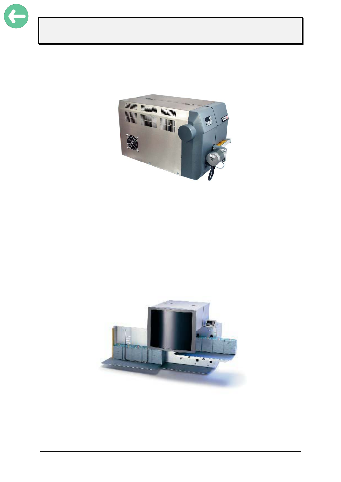
Unpacking of Printer
• Remove top foamed packing.
• For removing the printer off the box, take it at the base plate only and lift.
A second person should assist by removing the cardboard box downwards.
Note: Front cover, motor of optional knife must not be used as carrying
handles.
• Set unit to a plain and stabile desk.
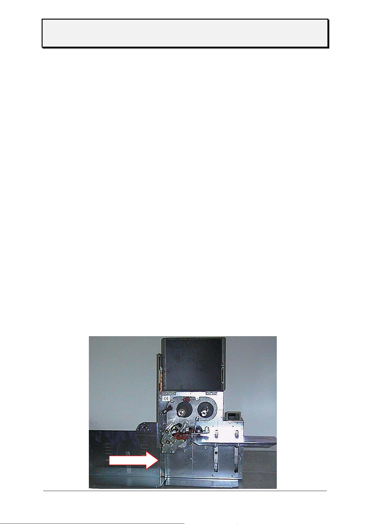
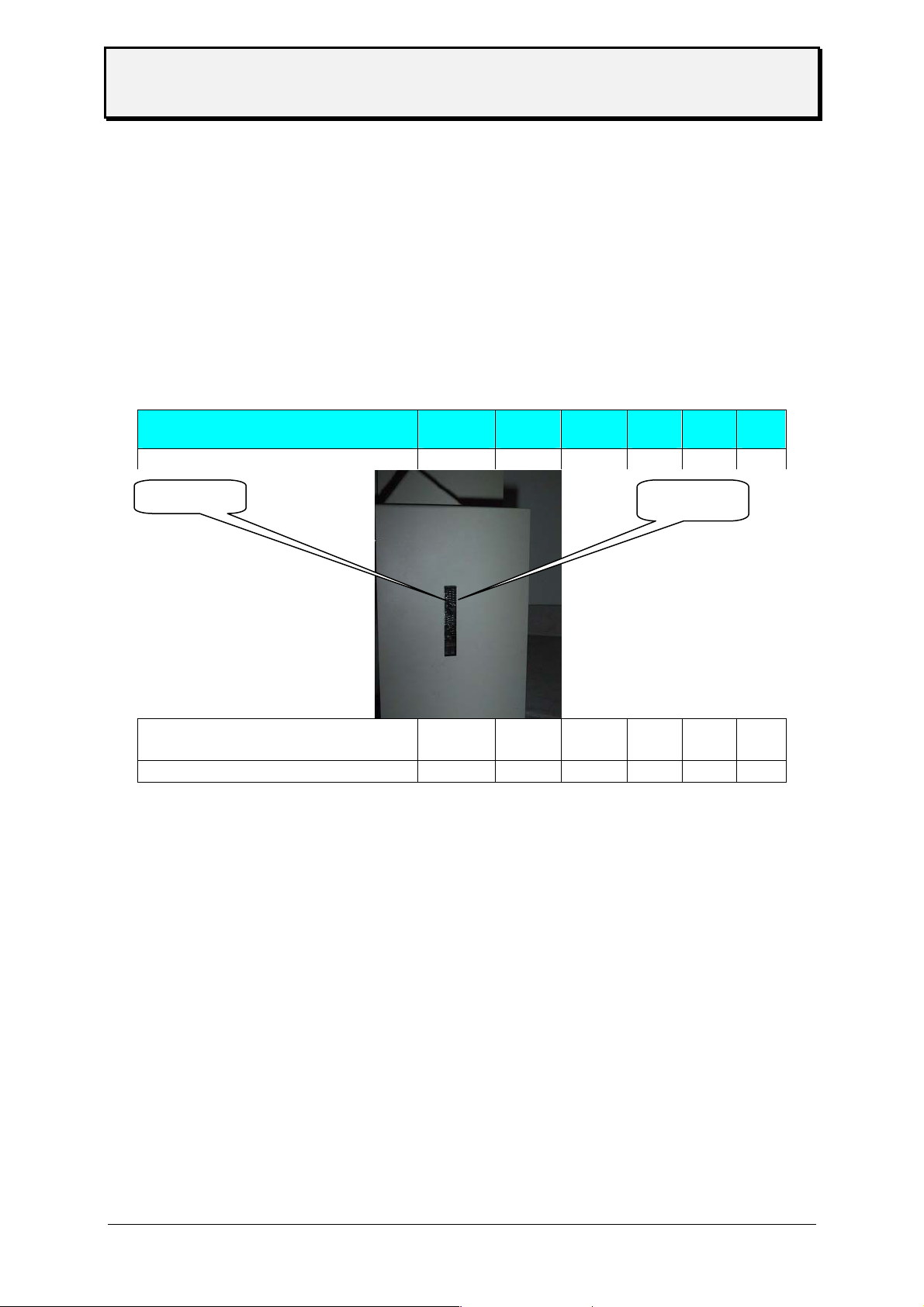
• -TDI / EXXTREME / S TDI only-
• Mount paper tray in and out, bow and length position stick according to picture
below
• Carry unit only by taking it at the base plate
Note: Front cover, motor of optional knife must not be used as carrying
handles.
05/08 Rev. 2.14 5
Page 6
User Manual
TTX 450/650/950/1050 – Puma/Lion/Tiger/Tiger XXL – TDI/STDI/XXtreme –
S45/65/95/105
Set - Up and Connection of Printer
• Check mains voltage setting and fuses.
• The fuses can be replaced by turning the inserts .
Attention: Unplug mains power plug before checking/changing mains voltage or fuses!
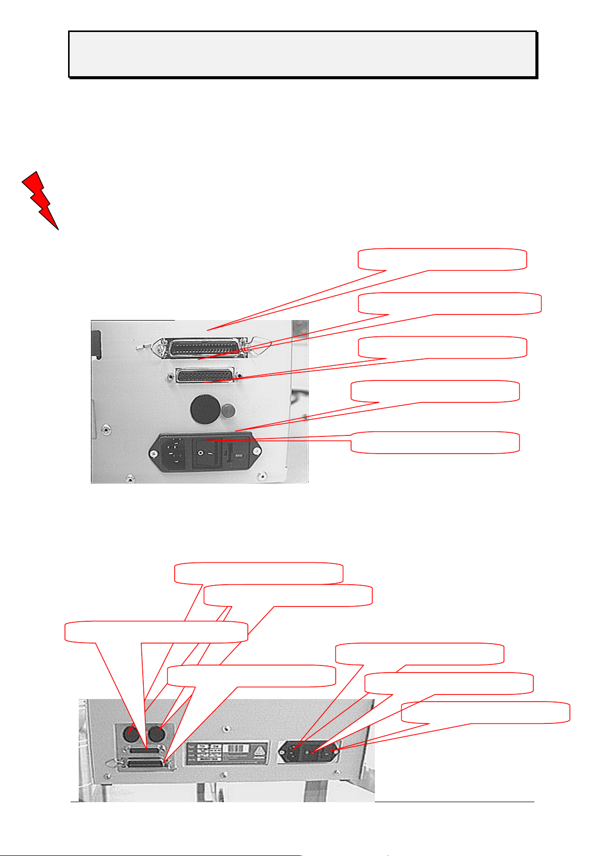
Centronics (parallel)
Connections TTX:
serial Inteface (RS 232 / RS
optionale connector
power select
power ON/OFF switch
Connections -TDI:
serial Inteface (RS 232 / RS
0
optionale connector 1
optionale connector 2
Centronics (parallel)
main power inlet
power ON/OFF switch
power select
05/08 Rev. 2.14 6
Page 7
User Manual
TTX 450/650/950/1050 – Puma/Lion/Tiger/Tiger XXL – TDI/STDI/XXtreme –
S45/65/95/105
Connection of External Units
A serial interface V.24/DB25 (RS232) and a parallel interface (Centronics) are
integrated as standard for connection of the printer to the computer.
Optional there is a RS 485 interface available - the RS 232 can be (factory
installed) removed and changed to a RS 485 interface. Be aware that the RS
232 interface then is removed !
The rear side of the unit is, in addition, equipped with one ore two sockets for the
connection of an external unit.
Attention: Turn off unit prior to plugging/unplugging interface cable/stacker connector
Exclusively units tested in accordance with IEC 950 and VDE 0805-which are in
compliance with these standards according to SELV- must be connected to
interface and stacker socket.
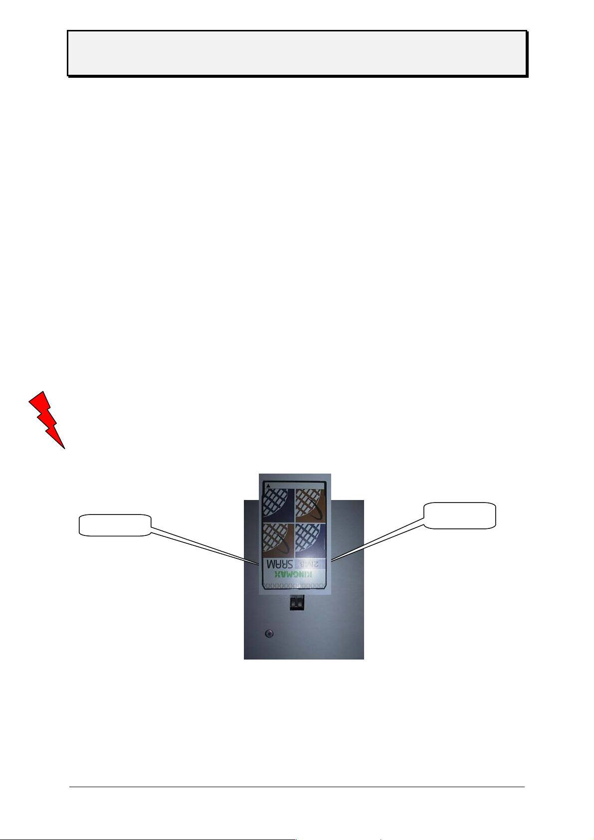
Card Plug in Modules
These plug in modules are provided for the optional font and logo cards. Use
PCMCIA cards up to a size of 2 MB only. There is a maximum of 1 logo card
alone or together with a font card – as well one or two font cards are possible.
Logo Cards and data bank cards are formatted by the printer itself.
Font cards are to be programmed by supplier only.
Attention: Exclusively plug in cards approved by the manufacturer must be used Insert,
remove, or exchange card not until 60 seconds after disconnection of unit.
SLOT 0
SLOT 1
SLOTS TTX
05/08 Rev. 2.14 7
Page 8
User Manual
TTX 450/650/950/1050 – Puma/Lion/Tiger/Tiger XXL – TDI/STDI/XXtreme –
S45/65/95/105
SLOTS TDI
Card hardware
printer
type
card
type
quantity
card
memory
of card
PROM
card
S-RAM
card
Flash
card
SLOT 1
TTX 450/650/950/1050/Puma/Lion/
Tiger/Tiger XXL
TDI PCMCIA 2 2 MB - yes yes
PCMCIA 2 2 MB - yes yes
SLOT 0
05/08 Rev. 2.14 8
Page 9
User Manual
TTX 450/650/950/1050 – Puma/Lion/Tiger/Tiger XXL – TDI/STDI/XXtreme –
S45/65/95/105
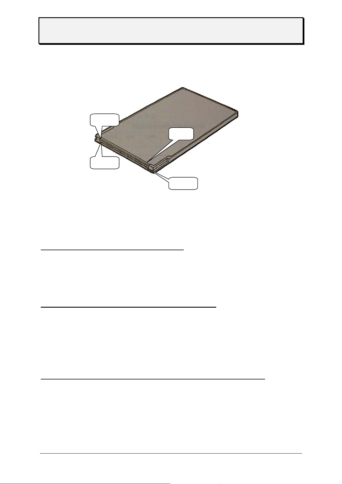
PCMCIA card pin assignment
Pin 34
Pin 1
Pin 68
Pin 35
Memory types
PROM card (Programmable Read Only Memory)
Programmable only with a special program unit (EPROM burner) – it is a on time card,
normally used to store fonts and logos witch are used again and again in the same shape
size or look like. The card will be programmed in the factory due to the customer wishes.
Memory size and capacity depends to the printer.
EPROM card (Erasable Programmable Read Only Memory)
Programmable only with a special program unit (EPROM burner) – it is a on time card,
normally used to store fonts and logos witch are used again and again in the same shape
size or look like. The card will be programmed in the factory due to the customer wishes. The
difference between EPROM and PROM card is that the EPROM card can be cleared by
using ultra violet light.
Is not used in our printer.
EEPROM or E²PROM (Electric Erasable Programmable Read Only Memory)
The function is similar to an EPROM card – to clear the memory there is no light used, it
works with electric power. The clear procedure is very slow. The data are hold in the memory
after power down – without battery !
Is not used in our printer.
05/08 Rev. 2.14 9
Page 10
User Manual
TTX 450/650/950/1050 – Puma/Lion/Tiger/Tiger XXL – TDI/STDI/XXtreme –
S45/65/95/105
FLASH RAM / PROM card
A name used and defined by the company INTEL witch has used this technology first. The
memory is build similar to the EEPROM but can be cleared in single sectors. A low voltage
(5V) is enough to clear the memory and this voltage is available in the most places
(PC/printer). The clear procedure is very fast, the data’s are stored in the memory after
power down – without battery.
This card is re programmable and can be programmed in a PC with the data’s. Stored on this
card type can be fonts and logos – same as on the EPROM card. In difference it is possible
to store as well formats.
Memory size is different depending on card type and printer.
RAM card (Random Access Memory)
Very fast, volatile memory. Each single memory cell is programmable and readable. Using
RAM card means that a battery is used to make the memory non volatile- the data’s are still
in the memory after power is switched off, reasoned by the power of the battery.
The card type is re programmable and depending on the printer type the card can be
programmed in the printer (via down load) or at the PC. It is possible to store – similar to the
EPROM card, as well logos fonts but different to the EPROM card as well formats.
Memory size is different depending on card type and printer.
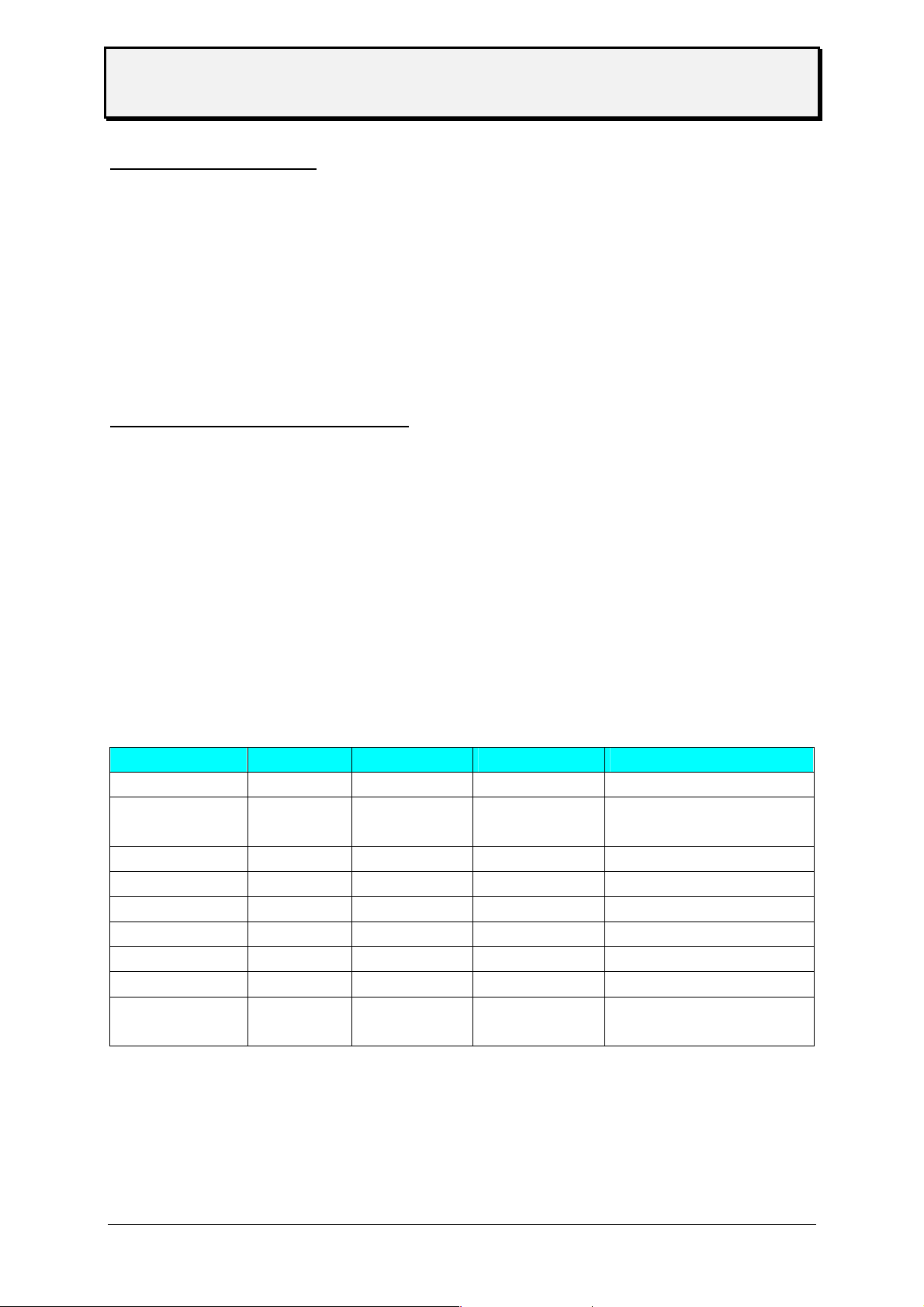
Card use
Depending on the printer type the cards can be used different. Attached you will find a table
showing card type, menu point to clear the card – where the card has to be formatted – and
as well the quantity of files.
card type menu point formatting formatting quantity of files
Easy Card
Format Card
Logo Card LCLR intern --Font Card DOWN intern DOS one, „V55_CARD.BIN“
Speedo Card DOWN intern DOS one, „PROMFILE.BIN“
DOS Card --- DOS as much as you want
Database Card DOWN intern one & Index
Barcode Card --- intern --Image Card ICLR intern ---
--- DOS as much as you want
(max. memory)
Card type
Note: For more information please refer to the card manual.
05/08 Rev. 2.14 10
Page 11
User Manual
TTX 450/650/950/1050 – Puma/Lion/Tiger/Tiger XXL – TDI/STDI/XXtreme –
S45/65/95/105
Set up mode
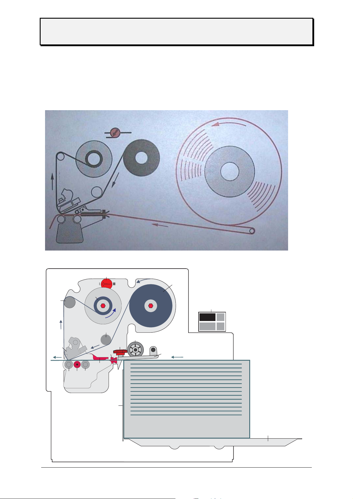
Winding Diagrams
TTX x50 / Wildcats
TDI / XXtreme
4
3
10
15
5
9
16
17
1
14
2
7
11
8
13
12
6
Z0133.cdr
05/08 Rev. 2.14 11
Page 12

User Manual
TTX 450/650/950/1050 – Puma/Lion/Tiger/Tiger XXL – TDI/STDI/XXtreme –
S45/65/95/105
Please follow during media / ribbon change the upper diagrams ! This is showing
the used directions of ribbon and media ( insert ribbon – insert media)
Attention : Sometimes it is helpful to release the head and rotate the head to insert ribbon
into the printer (esp. For TTX 450 / Puma / S 45) ! As well rotating the head
means that the wires connected to the head can be to short – then please
disconnect the wires – only if the printer is switched OFF ! Do not forget to
connect again – and check if the connectors are properly mounted !
This is shown in the following chapters as well.
05/08 Rev. 2.14 12
Page 13

User Manual
TTX 450/650/950/1050 – Puma/Lion/Tiger/Tiger XXL – TDI/STDI/XXtreme –
S45/65/95/105
Insertion of Document Material
Attention: Insertion/exchange of foil and material should be carried out only by especially
instructed personal.
• Open front over
• -TTX 650 / LION / S65 only-
Hang document material in reel holder in a way to ensure anticlockwise
unwinding. Put outer guide disk onto mandrel.
Guide material around the dancer.
05/08 Rev. 2.14 13
Page 14

User Manual
TTX 450/650/950/1050 – Puma/Lion/Tiger/Tiger XXL – TDI/STDI/XXtreme –
S45/65/95/105
• - only for TTX 1050
there is a special support which has to be opened before media can be loaded
or removed.
After removal or change of media – please close the support again.
-TDI/ EXXTREME/S TDI onlyMove paper tray down by means of simultaneously pressing ON/OFFLINE and
CUT key. Insert material to the left/rear corner of tray. Move paper tray up by
means of simultaneously pressing ON/OFFLINE and FEED key.
• Adjust lateral material guides (red) that the material may move easily.
-TTX 650/ LION / S 65 onlyPress the red lift lever at the right, outer end of the print module in order to lift the
pressure rolls of the feed roller and insert material below the printhead.
• Adjust both pressure roll units symmetric to material with so that material moves
smoothly.
• On printer versions with installed knife a straight cut edge is required for perfect
material insertion.
Attention: Do not touch feed unit with your free hand. The optional knife may cause
injuries with wrong key manipulations! On operation with open cover, fingers,
hair, clothes, jewellery, etc. may be caught by and get into the unit in the ribbon
feed section.
05/08 Rev. 2.14 14
Page 15

User Manual
TTX 450/650/950/1050 – Puma/Lion/Tiger/Tiger XXL – TDI/STDI/XXtreme –
S45/65/95/105
Material exchange
• Switch printer to OFFLINE mode and lift printhead by brief pressing of the
(FF)-key.
• Remove material by pressing the red lift lever and drawing the material
backward.
• -TTX 650 / LION / S 65 only-
By pressing the ON/OFFLINE and CUT key simultaneously the material will be
transported backward.
• -TDI / EXXTREME / S TDI only-
Move paper tray down by means of simultaneously the material will be
transported backwards automatically.
• Remove material off the mandrel or paper tray.
• For continuing steps see description above.
Insertion of fan folded material
• -TTX 650 / LION / S 65 only-
• Remove blade at rear side of unit.
• Set outer material guide disk according to width of material.
• Insert material with imprint side up.
• For continuing steps see description: Insertion of material.
Insertion of Thermal Transfer Ribbon
• Attach ribbon reel onto foil mandrel on the right-hand side for anticlockwise unwinding of
ribbon. Attach empty ribbon core onto mandrel on left-hand side.
• Insert ribbon end diagonally from the front under print-head holder or between knife cover
and printhead holder with open hinge drive mechanism. If foil is changed during a print job,
lift print head by short depression of the FF key.
05/08 Rev. 2.14 15
Page 16

User Manual
TTX 450/650/950/1050 – Puma/Lion/Tiger/Tiger XXL – TDI/STDI/XXtreme –
S45/65/95/105
• Pull ribbon upward and simultaneously move it towards printer.
• Guide ribbon around feed roller and attach it to ribbon core in anticlockwise direction
(ribbon may be folded so that adhesive part at start of ribbon can be used).
• -TTX 650/ LION / S 65 only-
By simultaneous depression of the (ON/OFFLINE)-and (FF)-keys, material and ribbon can
be advanced until perfect unwinding of ribbon is warranted.
• -TDI/XXTREME / S TDI only-
By pressing 2x the CUT key at OFFLINE mode at the display appears FOIL.
Subsequently by depressing the ON/OFFLINE key, the ribbon may be fed. Leave operation
by pressing FFED key 2 times back to OFFLINE mode.
Attention: Fingers, hair, clothing, jewellery, etc. may be caught by and get into the unit in
the ribbon feed section!
05/08 Rev. 2.14 16
Page 17

User Manual
TTX 450/650/950/1050 – Puma/Lion/Tiger/Tiger XXL – TDI/STDI/XXtreme –
S45/65/95/105
• - only for TTX 1050
Similar to the media unwind – the ribbon mechanic is supported as well. Open the handle to
remove / change ribbon and close the support again.
Adjustment of ribbon unwind rewind tension
The torque of ribbon unwind and rewind mandrels are adjustable by means of the red
hexagon pin .
The ribbon should run free of wrinkles respectively should not be stretched (especially at
drum section) over the whole run from roll to roll.
Increase of torque at unwind rewind mandrel Ribbon must not be stretched
Decrease of torque at unwind rewind mandrel Ribbon must not have wrinkle
The factory adjustment covers a wide range of ribbon width which is the main factor for
the torque. Use of very narrow and very wide ribbon however may need a readjustment.
05/08 Rev. 2.14 17
Page 18

User Manual
TTX 450/650/950/1050 – Puma/Lion/Tiger/Tiger XXL – TDI/STDI/XXtreme –
S45/65/95/105
Positioning of gap sensor
Depending on the printer different sensor are possible. Using the TDI two sensor are
available – through light and reflective. Using the TTX three sensor are possible (through
light, reflective and full size).
Between trough light and reflective there is a difference of 11 mm (adding). The optional full
size sensor is behind the standard sensor. The sensor can be moved across the web – and
the gap can be sensed . The minimum label width is extended to 38 mm.
Adapt sensor to the position of the gap by means of the adjusting knob located at the front
side of the print module. Adjustment range: 2-15mm across the web.
• A scale is marked around the knob
• Calculate position as follows. Measure distance between center of gap and left
edge of material reduce value. by 2 the results matches the adjustment value at
the scale
Sample :
Distance between center of gap and left edge of material 11mm
Reduction - 2mm
Adjustment value 9mm
With round labels punch - offset pre adjustment is possible at the printer (parameter
PUNO) or via Easy Plug command in order to correctly catch the label edge.
05/08 Rev. 2.14 18
Page 19

User Manual
TTX 450/650/950/1050 – Puma/Lion/Tiger/Tiger XXL – TDI/STDI/XXtreme –
S45/65/95/105
Adjust position of printhead
The zero line of the printhead can be varied from 2 - 13 mm of the left material edge
(this is only true for TTX 650, 950, 1050, TDI – not for the TTX 450)
• Loosen screw at center of printhead axle and set printhead to required
position.
Attention: Printhead must not be plugged off !
• Fix screw
• Loosen black plastic disk at ribbon rewind and unwind mandrell by means of 2
mm
allen key
• Adapt them both to position of printhead zero line and tighten again
Adjust pressure of printhead
Different material width may require different pressure of printhead to material in order to
optimise the print quality.
• 3 grades are available.
• Rotate the adjustment disk by means of a coin or screwdriver to the required
position.
Note: Select pressure only as high as necessary for the best print quality. Too
high pressure may lead to damages at the printhead.
thin media / small media
thick media / wide media
05/08 Rev. 2.14 19
medium media / medium
Page 20

User Manual
TTX 450/650/950/1050 – Puma/Lion/Tiger/Tiger XXL – TDI/STDI/XXtreme –
S45/65/95/105
Adjustment to thickness of material
• -TDI/EXXTREME / S TDI only-
The function of separating / transport roll at the paper tray has to be adapted to different
thickness off materials in order to ensure a correct label run.
The adjustment wheel is located between paper tray and lateral material guide, a bit offset in
the base plate of the print module. It carries a red, a yellow and a green arrow.
Adjust following:
• When using thin material 2 and/or more Rotate wheel clockwise
tags are drawn in
• When using thick material, Rotate wheel anticlockwise
none tag will be drawn in
The coloured arrows may be positioned at the wheel in order to set marks for different types
of tags.
Clip
05/08 Rev. 2.14 20
Page 21

User Manual
TTX 450/650/950/1050 – Puma/Lion/Tiger/Tiger XXL – TDI/STDI/XXtreme –
S45/65/95/105
Installation of option
for TTX 650 / LION / S 65
Attention: Some of the options – like the dispenser module can only be mounted by service
personal ! Sometimes it is necessary that a module can be imbedded only from a
defines series number – see option manual.
Unplug main power supply!
• Plug light-barrier connector and motor connector in. Both sockets are
located at front side of housing.
• Fasten unit by means of 2 hexagon socket screws at vertical base plate
of printer.
• Reconnect power supply and switch unit on.
Attention: Hazard of injury in the initialisation process and during cutting because of moving
knife!
• to activate the option go the parameter ‘PEPH’ and select the option with the
necessary parameter
• follow the steps in the option manual
A special case is the color option – therefore you have to install a separat firmware
and add an additional sensor. For more details refer to the color manual.
connecting
05/08 Rev. 2.14 21
Page 22

User Manual
TTX 450/650/950/1050 – Puma/Lion/Tiger/Tiger XXL – TDI/STDI/XXtreme –
S45/65/95/105
Short Tag Option
- for TDI / XXTREME / S TDI-
This option is used to handle short label (between 50 mm and 105 mm). The short tag option
is a second feed system driven by the main feed roller. A belt is connecting the main feed
roller with the short tag option. The label is transported from the separator to the short tag
option and from there to the feed section of the printer.
Attention: The option can be mounted to a printer by a service technician from a defined
serial number on ! From serial number SN 6800131605 on you can upgrade the
unit definitely ! This can only be done by a service technician.
Activate the shot tag option under menu point SECF (select YES)
OFF
INFO PRTP IFAC SYSP
EMUL
NACH
SENS
PUNS
FMOD
OMOD
SMOD
MMOD
LPOS
SECF
YES?
Fonts
Most the fonts used in the printer firmware are proportional – only the OCR fonts are non
proportional. This is given by the specs of this fonts.
Proportional font this means that all characters have a specific width
Non proportional font all characters have the same width
05/08 Rev. 2.14 22
Page 23

User Manual
TTX 450/650/950/1050 – Puma/Lion/Tiger/Tiger XXL – TDI/STDI/XXtreme –
S45/65/95/105
Modes of operation - operation
New Start of Printer
Connect printer to main power
Connect printer to computer
Switch on printer Display: OFF
Switch located at rear side of unit
Acknowledge by ON/OFFLINE key Display: ON
The printer is ready to receive data via the selected interface
Restart of Printer
Restart of printer without disconnection of unit by simultaneous operation of all three keys.
Note: All data stored in the printer will be deleted.
Call of Program Version
The program version is displayed during Reset – example 1H34
05/08 Rev. 2.14 23
Page 24

User Manual
TTX 450/650/950/1050 – Puma/Lion/Tiger/Tiger XXL – TDI/STDI/XXtreme –
S45/65/95/105
Modes of operation - OFFLINE
‘FEED’ and ‘CUT’ simultaneously = program or ‘ESC’
‘FEED’ -’CUT’ and ON/Offline simultaneously = Reset
OFFLINE MODE TTX 450, 650, 950 - S 45, 65, 95 - Puma, Lion, Tiger
Display Key Display function
OFF ON/OFFLINE ON ready to receive
OFF ON/OFFLINE FEED <-- slow media and ribbon movement
OFF ON/OFFLINE CUT cut and media backwards
OFF FEED FEED feed of media
OFF CUT CUT cut ( if the optional cutter is available)
OFF FEED CUT INFO enter the parameter menu
OFFLINE MODE TDI, XXTREME, S TDI
OFF ON/OFFLINE ON printer is ready to receive data
OFF ON/OFFLINE FEED UP move magazine up, if parameter MMOD = TAG
OFF ON/OFFLINE CUT DOWN move magazine down, if parameter MMOD = TAG
OFF FEED FEED feed of media
OFF CUT FOIL slow ribbon feed, to stop press CUT
ON/OFFLINE
OFF FEED CUT INFO enter parameter menu
status message
ST .. ON/OFFLINE press key to cancel the status
FEED turn off acoustic signal
CUT leave status message to OFFLINE mode
05/08 Rev. 2.14 24
Page 25

User Manual
TTX 450/650/950/1050 – Puma/Lion/Tiger/Tiger XXL – TDI/STDI/XXtreme –
S45/65/95/105
Modes of operation - ONLINE
‘FEED’ and ‘CUT’ simultaneously = program or ‘ESC’
‘FEED’ - ‘CUT’ and ON/OFFLINE simultaneously
= RESET
ONLINE MODE
Display Key Display function
ON FEED CUT HV.. energy
changing with FEED - (less)
changing with CUT + (more)
WAIT not possible WAIT image built up
XXXX display quantity of printable label including the one in
process
XXXX ON/OFFLINE STOP the label in process will be finished then the display starts
flashing
XXXX
STOP ON/OFFLINE OFF change to OFFLINE mode (quantity unchanged)
XXXX
OFF ON/OFFLINE STOP OFFLINE Mode – printout is stopped
XXXX
STOP FEED XXXX print job start again
XXXX
Parameter menu coming from OFFLINE Modus
Display key display function
OFF FEED CUT INFO enter parameter menu
INFO FEED CUT OFF leave parameter menu
INFO FEED selection
INFO CUT selection
05/08 Rev. 2.14 25
Page 26

User Manual
TTX 450/650/950/1050 – Puma/Lion/Tiger/Tiger XXL – TDI/STDI/XXtreme –
S45/65/95/105
Maintenance and cleaning
Clean printhead and feeding roller with cleaning liquor from paper, adhesive
and ink deposits at regular intervals.
Cleaning the printhead
• Disconnect unit
Attention: Pull off mains plug!.
•.Remove material and ribbon.
• Loosen hexagon socket screw at center of printhead axle by means of a
2mm allen key, until the printhead can be rotated clockwise.
Attention: The printhead is an electronic module and highly sensitive to static impacts. For
that reason discharge your static potential before going in contact with the
printhead by gripping the base plate of the printer. Do not remove plugs from the
printhead. If printhead is readjusted at axle mark ist position accordingly.
• Clean print roller with dust-free cloth and cleansing liquor only.
Attention: Never use knives or objects with sharp edges for cleaning. Metal objects must
never get in contact with the dot line.
• Put printhead to former position and fix screw again.
Note: The screw enters a non visible gap at the axle, which ensure the correct
position of the printhead. Factory adjustment is flash with the inner black
plastic bushing.
• Before switch on the unit, check that both connectors of printhead are still
plugged on correctly. Reconnect if necessary.
05/08 Rev. 2.14 26
Page 27

User Manual
TTX 450/650/950/1050 – Puma/Lion/Tiger/Tiger XXL – TDI/STDI/XXtreme –
S45/65/95/105
Exchanging the printhead / TTX x50
1. Disconnect unit
Attention: Pull out the mains plug!
2. Remove material and ribbon.
3. Remove plugs from printhead in horizontal direction.
Note: Remove printhead cable from printhead not until 3 minutes from
disconnection of unit.
4. Loosen the 2 red marked screws at fixation of printhead.
5. Loosen screw at center of printhead axle - until the printhead fixation can be
rotated clockwise.
Attention: The printhead is an electronic module and highly sensitive to static impacts. For
that reason discharge your static potential before going in contact with printhead
by gripping the base plate of the printer. If printhead is readjusted at axle mark
its position accordingly.
6. Let the printhead down to print roller and rotate the fixation clockwise.
7. Draw printhead carefully out of the print module.
Attention: Metal objects must never get in contact with the dot line. Do not touch printhead
at dot line or connectors.
8. For reassembling putt the printhead on the 180° rotated fixation, positioning is
done by means of the 2 upright bolts.
Note: Before mounting notice the resistor value of the printhead-noted at
printhead. Special care is to be taken that printhead is supported flush on
mounting plate.
9. Keep printhead and fixation together with fingers, rotate anticlockwise to print
roller.
10. Refix printhead by means of the 2 red marked screws at fixation bar.
11. Put printhead on axle to former position and fix screw again.
Note: The screw enters a non visible gap at the axle, which ensures the correct
position of the printhead. Factory adjustment is flash with the inner black
plastic bushing.
12. Plug on the 2 connectors to printhead.
13. When exchanging the printhead the value of the head resistor has to be keyed in
after restart.
Attention: Entry of an incorrect value may damage the printhead!
14. Repositioning of printhead to print roller
05/08 Rev. 2.14 27
Page 28

User Manual
TTX 450/650/950/1050 – Puma/Lion/Tiger/Tiger XXL – TDI/STDI/XXtreme –
S45/65/95/105
Production tolerances at printhead may cause to move the printhead in or versus
print direction. This is performed by twisting the little screws at the guiding tooth
when fixing screws are loose (tools are supported with printer)
Note: The optimal position can be found by print only !
Exchanging the printhead / TTX 67x
The print head is adjusted to the print head mounting during manufacture. As a
result the print head can only be replaced in conjunction with the print head
mounting.
1. Switch off the device.
2. Pull out the mains plug.
3. Remove material and ribbon.
4. Pull out both plugs in a horizontal direction from the print head.
Note: Wait at least 3 minutes after switching off the device before removing the
print head cable from the print head. Mark the position of an axially
adjusted print head.
6. Unscrew the two thumb screws on the print head mounting until the entire print
head mounting can be removed from the contact shaft (see Fig. 1:).
Fig. 1: Take care not to touch the connector contacts (1) or
the thermal edge (2) when removing the printhead!
1
2
Attention: The print head is a sensitive electronic component and can be damaged by
electrostatic charges. Therefore, discharge any bodily static electricity before
coming into contact with the print head by touching the base plate of the printer.
The print head may not be touched on the print bar or on the plug-in contacts.
8. To install, move the new print head mounting to the old position and tighten the
thumb screws.
Note: Before doing this make a note of the resistance value of the print head
(read off from the print head). When placing the print head on the print
head mounting, ensure that the print head is lying flat.
05/08 Rev. 2.14 28
Page 29

User Manual
TTX 450/650/950/1050 – Puma/Lion/Tiger/Tiger XXL – TDI/STDI/XXtreme –
S45/65/95/105
Note: Press the thumb screw on the tapered edge of the square axle and
ensure the exact positioning of the print head mounting on the axle. Also
pay attention to the position of the print head in relation to the edge of the
label.
Basic factory settings: Flush against the inner black plastic plug.
9. Plug the print head cable back into the print head.
10. The resistance value of the print head must be entered after putting the printer
into operation using the parameter "SYSTEM PARAMETERS/ Head resistance".
Attention: Entering a false value can damage the print head!
Note: Please also read the Service Manual, topic section "Service print
module", paragraph "Exchanging the printhead".
Cleaning of Print Roller
• Disconnect unit
Attention: Pull off mains plug!
• Remove material and ribbon.
Loosen screw at center of printhead axle - until the printhead fixation can
be rotated clockwise.
Attention: Do not remove plugs form the printhead. If printhead is readjusted at axle mark
its position accordingly.
• After performance of this step, the feed roller as well as the print roller is
accessible from above.
• Clean print roller with dust-free cloth and cleansing liquor only.
• Rotate roller stepwise for complete cleaning.
Attention: Never use knives or objects with sharp edges for cleaning.
The feed roller and the friction rollers are also to be cleaning from time to time.
Performance of the printer and particularly the printhead is generally increased
by avoiding any type of contamination in the printing area.
In addition, neat printing results are preferable to poor ones in any case.
• Put printhead to former position and fix screw again.
05/08 Rev. 2.14 29
Page 30

User Manual
TTX 450/650/950/1050 – Puma/Lion/Tiger/Tiger XXL – TDI/STDI/XXtreme –
S45/65/95/105
Note: The screw enters a non visible gap at the axle, which ensures the correct
position of the printhead. Factory adjustment is flash with the inner black
plastic bushing.
• Before switch on the unit, check that both connectors of printhead are still
plugged on correctly. Reconnect if necessary.
Clean feed roller for single tags -
TDI / XXTREME / S TDI only-
• switch off device
Attention: Pull off mains plug!
• the feed roller should be cleaned with a dust free towel together with the
Avery roller cleaner
From time to time the separation edge and the bearings should be cleaned
Cleaning will help to extend the runtime of your device !
Attention: Cleaning of that roll on a regular basis is influencing the accuracy of the imprint
of your device. Please clean at least two times a day !
Clean Short Tag Option - TDI / XXTREME / S TDI only-
• switch off device
Attention: Pull off mains plug!
• if the Short Tag Option is built in, you have to clean the additional feed roller
as well – use a dust free towel ad the Avery roller cleaner.
• please clean as well the pressure roller
Cleaning of Punch-Recognition Sensor
According to the materials applied, the light barriers is to be cleaned from
material residues and dust by means of compressed air.
• Disconnect unit
Attention: Pull off mains plug!
05/08 Rev. 2.14 30
Page 31

User Manual
TTX 450/650/950/1050 – Puma/Lion/Tiger/Tiger XXL – TDI/STDI/XXtreme –
S45/65/95/105
• Remove material and ribbon.
• Loosen screw at center of printhead axle - until the printhead fixation can
be rotated clockwise.
Attention: Do not remove plugs from the printhead. If printhead is readjusted at axle mark
its position accordingly.
• After performance of this step, the sensor are accessible from above.
• Clean sensor with air pressure only.
With heavy contamination additional cleaning using a dust-free cloth and
cleansing liquor is recommended.
• Put printhead to former position and fix screw again.
Note: The screw enters a non visible gap at the axle, which ensure the correct
Position of the printhead. Factory adjustment is flash with the inner black
plastic bushing.
• Before switch on the unit, check that both connectors of printhead are still
plugged on correct. Reconnect if necessary.
Cleaning of ribbon guiding parts
Adhesive residues are to be removed at regular intervals upon processing
of self-adhesive material to ensure perfect print quality.
Clean parts with dust-free cloth and cleansing liquor only.
Contaminated parts affect the feed of the ribbon and will reduce the print
quality.
Cleaning of knifes - TTX 650 / LION / S 65 only -
Adhesive residues are to be removed at regular intervals upon processing
of self-adhesive material to ensure perfect material cut and unwinding.
Attention: Pull of mains plug
Be aware of sharp edge of knife which could cause injury.
Remove adhesive residues from upper and lower knife; in case slightly
swivel knives for better access to the entire edge.
Clean parts with dust-free cloth and cleansing liquor only.
05/08 Rev. 2.14 31
Page 32

User Manual
TTX 450/650/950/1050 – Puma/Lion/Tiger/Tiger XXL – TDI/STDI/XXtreme –
S45/65/95/105
Other
MATERIAL AND RIBBON
Material
The printer is equally suitable for thermal and thermal transfer printing. Three
factors are to be taken into account when choosing the material:
• Abrasive behaviour of the surface structure
• Properties with respect to chemical reaction on print-colour transfer
• Temperature required for colour- transfer
If the material is extremely abrasive, the printhead is faster worn as usual.
This criterion is particularly to be considered with thermal printing. It is not so
critical with thermal transfer printing, as for this process a ribbon of a width
exceeding the width of the material can be used. In this way the printhead is
protected over the entire material width.
Similar conditions prevail with a high printhead temperature. Material and foil
require a longer cooling down period, the printing quality is more critical and
the printhead is faster worn as on a normal rate.
Printing on materials with a higher specific weight than 240gr/sqm, slight
corrections of printhead pressure and position of printhead may be
necessary.
Ribbons
Ribbons are recommended to be:
• the rear side has to be coated with an anti static and friction reducing
media (back coating)
• suitable for print speeds up to 12 inches/second
• specified to „Near edge type printhead“
• wider as the material, i. e. the ribbon overlap the edges of the material by
appr. 1-2 mm each side.
Ribbons without these features may reduce printer performance and
printing quality, in some cases even the printhead may become defect.
05/08 Rev. 2.14 32
Page 33

User Manual
TTX 450/650/950/1050 – Puma/Lion/Tiger/Tiger XXL – TDI/STDI/XXtreme –
S45/65/95/105
Printer layout
Note: The printhead zero line may be repositioned in a range of 2-13mm in relation to
the label zero line.
This affects also the horizontal position of the print image
Also the ribbon zero line may be varied in relation to the label zero line.
Layout TTX
05/08 Rev. 2.14 33
Page 34

User Manual
TTX 450/650/950/1050 – Puma/Lion/Tiger/Tiger XXL – TDI/STDI/XXtreme –
S45/65/95/105
Layout TDI
05/08 Rev. 2.14 34
Page 35

User Manual
TTX 450/650/950/1050 – Puma/Lion/Tiger/Tiger XXL – TDI/STDI/XXtreme –
S45/65/95/105
Technical Specification TDI
Print technology Thermal-and Thermal Transfer Print
Print head „Near Edge Type“ print head, high resolution, fast, with integrated
temperature control.
Print speed 100 up to 250 mm/s in steps of 25,4 mm/s (1 “/s)
Resolution 12 Dots/mm (300 dpi)
Effective print width 128 mm
Imprint exactness Up to 100 mm label length: +/- 1 mm in X and Y direction
More than 100 mm label length: 1% of the label length
Label size Width: 25,2 (short tag 50mm) up to 154 mm
Length: 105 mm (short tag 50mm) up to ca. 350mm
Label length 105 mm up to max. printing length (standard device)
50 mm up to max. printing length (Short Tag option)
The max. printing length depends on the following points:
– Firmware intalled to the printer (standard or extended, furthermore of
the version of the respective firmware)
– Use of bar code cards
– Use of image cards
Depending on the combination of firmware, bar code card and image
card results a different maximum print length.
none 301 mm (324 mm*)
none 245 mm
1 x 1 MB S-RAM 339 mm
1 x 2 MB S-RAM 679 mm
2 x 2 MB S-RAM 1359 mm
Firmware Plug-in card
Standard (1H..)
Bar code card 242 mm
Extended (1X..)
Bar code card 197 mm
Tab. 1: The max. printing length can be extended by aid of S-RAM cards; assuming
that the special "extended firmware" (code 1X..) is installed. This firmware
takes more memory space than the standard firmware, that´s why the max.
printing length with extended firmware and without plugged-in S-RAM card
is even lower than with standard firmware.
*) with spooler set to 8 KB (standard: 65 KB)
Max. printing
length
P For detailed information on the different firmware versions refer to the
P For details about applying plug-in cards refer to the cards manual.
05/08 Rev. 2.14 35
Be aware, that the max. printing length may vary from one firmware
¯
version to the next. Adding features to the printer means often taking
away some millimeters of printing length from the image buffer!
service manual, topic section "Firmware", "Firmware Versions".
Page 36

User Manual
TTX 450/650/950/1050 – Puma/Lion/Tiger/Tiger XXL – TDI/STDI/XXtreme –
S45/65/95/105
Output mode 1:1 at 100% imprintable label area with or without cut.
Not imprintable area: 2 mm from lower side and 1 mm from left
(inner) side (fig.)!
Feed direction
1 mm not printable
Gap sensor Self initializing infrared gap sensor with adjustment range 2-17mm,
correction of gap offset possible; length of gap: 0,8 up to 14mm,
width: min. 4mm; optional reflex mark sensor
Interpreter Easy Plug, Line Printer, Hex Dump
Label Stock Specifications
Label stock Fan folded, single sheet or strip
Width 25.4 up to 154 mm (standard device)
50.0 up to 154 mm (Short Tag option)
Special case for Short Tag Option: Suitable tag stock can be used
¯
without the outer material guiding. In those cases, the minimum width
is 30.0 mm.
2 mm not printable
Type of stock Self-adhesive, tag or plastic label material
Thickness 0.1 to 0.5 mm
Weight 100 to 240 g/m
Crucial for the function is also the separability of the label stock:
P Continued overleaf.
05/08 Rev. 2.14 36
Not suitable is:
¯
Label stock with static charging surface
•
Label stock with adhesive surface
•
The label stock must generally be easy to separate, what means:
¯
it must not be talcum-powdered.
•
it must be free of punching burrs.
•
Label stock with sharp cutting edges must be processed so that the
¯
cutting edge faces the print roller! (otherwise printhead service life will
be decreased considerably)
2
Page 37

User Manual
TTX 450/650/950/1050 – Puma/Lion/Tiger/Tiger XXL – TDI/STDI/XXtreme –
S45/65/95/105
P See “Service Manual TTX 67x”, topic section “Service print module”,
Label stock which is thicker than 0.25 mm and/or heavier than
¯
240 g/m
done with a sufficiently large number of labels. Given a poor print
result, the printhead position must possibly be changed.
chapter “Adjusting the print head position”.
2
must be tested regarding printability. The testing must be
Ribbon specifications
Ribbon roll Roll max. outer ∅ 90mm, inner ∅ 1“ (25,4 mm)
Width 30 up to 132mm
Auto Economy Mode Starting up from > 10 mm imprint free length (on the last 32 mm of a
label only if SYSP/FMOD/SAVE is set to LEHU)
Fonts, Bar Codes
Fonts 17 Fonts inclusive OCR-A and OCR-B; 2 scaleable fonts
Character modification Margination in X/Yup to factor 8, rotation: 90,180,270 degrees
Barcodes EAN 8 and 13 with Add-On 2 and 5, UPC-A, UPC-E, Code 93,
Code 39 (Ratio 1:2, 1:2,5 and 1:3), Code ITF, Codabar, Code 128,
Code 2/5, Code 2/5 lnterleaved (Ration 1:2 and 1:3), Code 2/5 5,
Code 2/5 Matrix (Ratio 1:2, 1:2,5 and 1:3), Code MSI, Code EAN 128,
Postcode (Lead-and Identcode), UPS-Code 128
All bar codes in 16 widths, unlimited in height.
Operating Features
Operation 3 key panel with 4 digit display.
Adjustments Definition of parameters via menu or Easy Plug commands.
Test print outs of parameter adjustments, downloaded logos, font, line, and barcode
library.
Test functions Print tests with cut, Test routines to memory and sensors
Error messages Shows error messages on the display; continution of print jobs
without label loss
Connection, Device Data
Mains voltage 115/230/240 V +/- 10%, switchable
Mains frequency 50/60 Hz
Power consuption 336 VA
Current approx. 3 A at 115 V and 1,5 A at 230/240 V
Fuses 8 A at 115V, 6,3 A at 230 V and 6,3 A at 240 V
Ambient conditions Operation temperature: +5 up to +35 degree C
Storage temperature: -20 up to + 70 degree C
Humidity: 45 to 75%, non condensing
Dimensions WxHxD 840x420x380mm
05/08 Rev. 2.14 37
Page 38

User Manual
TTX 450/650/950/1050 – Puma/Lion/Tiger/Tiger XXL – TDI/STDI/XXtreme –
S45/65/95/105
Weight Approx. 25kg - without stock
Interfaces Standard: serial (RS 232) and parallel (Centronics) optional RS 485 -
in exchange against RS 232
Memory 1MB dynamic RAM
Cards 2 Slots for PCMCIA cards, 2 MB each
Certificates
TÜV GS Approved security (according to EN 60950:97)
CE conformity
The devices are marked with the CE label. The manufacturer
declares that the device conforms with the relevant European
guidelines.
EMC The EMC tests were performed according to the following norms:
EN 55022:98
EN 55024:98
EN 61000-3-2:95
EN 61000-3-3:95
EN 61000-6-2:99
Service Data
The data shown in STA3 can have a maximum value – shown in the table below. After that
value is reached the counter is set to zero and counts up again.
Number of service operations 255
Number of heads / rolls / knives 255
Head / roll run length 131 km
Cuts on knife 4.300.000.000
Total material length 430.000 km
Total foil length 430.000 km
Total number of cuts 4.300.000.000
Head moves 4.300.000.000
Head strobes 4.300.000.000
Operation time 8.800 years
05/08 Rev. 2.14 38
Page 39

User Manual
TTX 450/650/950/1050 – Puma/Lion/Tiger/Tiger XXL – TDI/STDI/XXtreme –
S45/65/95/105
INDEX
C
Card.......................................................7
Changing the print head......................28
Charges, electrostatic..........................28
Cleaning of Print Roller........................ 29
Cleaning of ribbon guiding parts..........31
Cleaning Printhead.............................. 26
Connections
TDI.................................................6
TTX................................................6
CONTENTS...........................................2
Copyright...............................................4
E
EMC..................................................... 38
Exchanging the Printhead ...................27
External Units........................................7
F
Fanfolded material...............................15
Font cards.............................................. 7
G
Gap sensor.................................... 18, 36
General..................................................4
I
INFO.................................................... 24
Initiation.................................................5
Insertion of Document Material............ 13
Interpreter............................................ 36
K
Knife option, installing.......................... 21
O
OFFLINE ............................................. 25
ONLINE MODE ................................... 25
Operating instructions
Printhead.......................................4
operation............................4, 23, 24, 25
Other.................................................... 32
P
parallel interface....................................7
parameter............................................24
PCMCIA card, pin assignment .............. 9
Plug-in cards
FLASH RAM / PPROM card .......10
PROM card ................................... 9
RAM card.................................... 10
use .............................................. 10
printhead............................ 19, 26, 30, 32
Printhead
adjust position of......................... 19
adjust pressure............................ 19
Program Version.................................. 23
PROMFILE.BIN...................................10
Putting into operation........................... 29
R
Resistance value thermal bar.............. 28
Restart................................................. 23
rewind.................................................. 19
Ribbon...........................................15, 32
Ribbon mandrels, setting torque.......... 17
Ribbon roll dimensions........................37
RS 232............................................. 7, 37
RS 485............................................. 7, 37
L
S
Layout............................................33, 34
M
Maintenance and cleaning................... 26
Memory types........................................9
MMOD .................................................24
05/08 Rev. 2.14 39
SECF................................................... 22
Sensor.................................................30
Set up mode........................................11
Short Tag Option.................................22
status message ................................... 24
Page 40

User Manual
TTX 450/650/950/1050 – Puma/Lion/Tiger/Tiger XXL – TDI/STDI/XXtreme –
S45/65/95/105
T
thickness of material............................20
Torque adjustment of ribbon mandrels 17
U
Unpacking printer .................................. 5
unwind.................................................19
05/08 Rev. 2.14 40
 Loading...