

Page 1

Users Manual
SS Finisher
Operation / Maintenance
and Parts List
AVERY DENNISON
Manual Edition 2.1
02 February 2011
Manual Part Number 421385
Page 2

This page intentionally left blank
Page 3

Contents
Warranty Information 7
Operation 9
Theory of Operation .................................................................................................... 9
Safety Issues / Warnings.............................................................................................. 9
Warning:...................................................................................................................... 9
Customer Responsibility.............................................................................................. 9
Location of SS Finisher ............................................................................................... 9
Unit Specification ....................................................................................................................10
Ultra Sonic Power Supply........................................................................................................ 11
Caution ...................................................................................................................... 11
Test Button ................................................................................................................ 12
AUTO/MAN Switch.................................................................................................. 12
CUTTING-CONTROL and US-TIME Controls ....................................................... 12
Power......................................................................................................................... 13
Connecting the Ultrasonic Power Supply .................................................................. 13
Loading the Machine ...............................................................................................................14
Loading the Tape ....................................................................................................... 14
Pressure Roller......................................................................................................................... 14
Pressure Roller Setting .............................................................................................. 14
Ultra Sonic Horn "Stack"......................................................................................................... 15
Cutter Set-up.............................................................................................................. 15
Remove Front Cover to Make Adjustments............................................................... 15
Squaring the Horn to the Blade ................................................................................. 16
Ground Detection Sonic Cutter ................................................................................. 17
Replacing the Top Knife Blade................................................................................................ 18
Overview: .................................................................................................................. 18
Note: .......................................................................................................................... 18
Leveling the Top Blade ............................................................................................. 19
Leveling the Top Blade ............................................................................................. 19
Adjusting Knife Spring Pressure: .............................................................................. 19
Knife Pressure ........................................................................................................... 20
Replacing the Top Blade ........................................................................................... 20
Proximity Switch Adjustment .................................................................................................. 22
Trouble Shooting 23
Ultrasonic Noise ...................................................................................................................... 23
Sonic Troubleshooting ............................................................................................................. 24
Control Panel Operation .......................................................................................................... 25
SS Finisher Controls.................................................................................................. 25
Start ........................................................................................................................... 25
Feed ........................................................................................................................... 25
Knife.......................................................................................................................... 25
Stop............................................................................................................................ 25
Indicator Lights........................................................................................................................26
Users Manual SS Finisher •••• 3
Page 4

On Line......................................................................................................................26
Sensor ........................................................................................................................26
Error........................................................................................................................... 26
Instrument Panel ......................................................................................................................27
Single Screen Input....................................................................................................27
Overview ...................................................................................................................27
Feed Length ............................................................................................................... 27
Cut Position ............................................................................................................... 28
Color Mark Sensor Adjustment................................................................................................29
Contrast Sensor.......................................................................................................... 29
Overview ...................................................................................................................29
Setup.......................................................................................................................... 29
LCD Display ............................................................................................................................30
Diagnostic Tests ........................................................................................................30
Recommended Spare Parts:......................................................................................................31
Troubleshooting Electrical ....................................................................................................... 32
Appendix A 33
Manufactures of Hearing Protectors ........................................................................................ 33
Appendix B 34
Error Messages ........................................................................................................................34
Appendix C 35
Label / Machine Speed.............................................................................................................35
Labels Rate Chart ......................................................................................................36
Appendix D 37
Multi Color Contrast Sensor Installation Instructions .............................................................. 37
Sensor Installation - Option No. 420014 ................................................................... 37
Teach-in Procedure:...................................................................................................38
Color Contrast Sensor Option Assembly ................................................................................. 39
Color Contrast Sensor Option Parts List.................................................................................. 39
Electrical Schematic 41
115V / 230V Schematic – Branson System ............................................................................. 42
Machine Interface Board Jumper Position ............................................................................... 43
Assembly Drawings Mechanical 45
Unwind Assembly.................................................................................................................... 46
Unwind Parts List..................................................................................................................... 47
Feed Pressure Roller Assembly................................................................................................48
Knife Assembly........................................................................................................................ 50
Knife Parts List ........................................................................................................................51
External Fan Assembly ............................................................................................................ 52
External Fan Parts List .............................................................................................................53
Conveyor Assembly.................................................................................................................54
Conveyor Parts List..................................................................................................................55
Stacker Assembly.....................................................................................................................56
Stacker Parts List .....................................................................................................................57
Users Manual SS Finisher •••• 4
Page 5

Tamper Assembly .................................................................................................................... 58
Tamper Parts List..................................................................................................................... 59
Drive Assembly ....................................................................................................................... 60
Drive Parts List ........................................................................................................................ 61
Contrast Sensor Assembly ....................................................................................................... 62
Contrast Sensor Parts List ........................................................................................................63
Cover Assembly....................................................................................................................... 64
Cover Parts List ....................................................................................................................... 65
Users Manual SS Finisher •••• 5
Page 6

Page 7

Warranty Information
Warranty Policy
Avery Dennison Retail Information Systems, In-Plant Printing Solutions provides the following warranty policy.
Scope
Warranties against defects from workmanship for equipment and parts manufactured and sold from Sayre,
PA. Includes time and material except as otherwise noted below.
Time
− New equipment and parts: 6 months
− Refurbished equipment and parts: 90 days
− Warranty period starts when equipment ships from selling location.
General Conditions
Avery Dennison extends warranty coverage under the following conditions.
− Equipment and parts will perform within published specifications. Promised or implied statements by any
Avery Dennison employee or representative will not be deemed to vary the terms of the warranty.
− Equipment and parts must be installed and operated according to recommended procedures and
operating conditions.
− Consumable elements are not covered. Consumable elements are those that show normal wear from
typical equipment usage including, without limitation, printheads, knives, rollers in contact with the web,
and sonic units. Avery Dennison reserves the right to determine which elements are defined as
“consumable.”
− No customer maintenance may be performed except as directed by qualified Avery Dennison personnel.
− Equipment and parts damaged by negligence or abuse are not covered.
− Avery Dennison US reserves the right in its sole discretion to incorporate any modifications or
improvements in the machine system and machine specifications which it considers necessary but does
not assume any obligation to make said changes in equipment previously sold.
Equipment Purchased In US and Shipped In US
− Avery Dennison US covers warranty for equipment and parts installed and operated in the Americas
(United States, Canada, Mexico, Central America, Caribbean Region, and South America excluding
Brazil).
− Outside the US, the local Avery Dennison office is responsible for equipment and parts warranty.
Customers must ensure coverage during machine purchase.
Users Manual SS Finisher Warranty Information •••• 7
Page 8

− Equipment purchased and exported to regions outside local Avery Dennison office coverage are not
covered by warranty. The purchasing agent must acquire a service contract from the Avery Dennison
office where the equipment or parts are operated to ensure machine coverage. For example, if an agent
purchases a printer in the US, exports to Brazil, and then needs warranty coverage, Avery Dennison Brazil
has no obligation to provide warranty coverage. The agent must purchase services from Avery Dennison
Brazil.
THE WARRANTIES PROVIDED HEREIN ARE EXCLUSIVE AND ARE IN LIEU OF ANY IMPLIED
WARRANTY OF MERCHANTABILITY, FITNESS FOR A PARTICULAR PURPOSE OR OTHER WARRANTY
OF QUALITY OR PERFORMANCE, WHETHER EXPRESS OR IMPLIED. EXCEPT THE WARRANTY OF
TITLE, IN NO EVENT SHALL AVERY DENNISON BE LIABLE FOR ANY INDIRECT, INCIDENTAL OR
CONSEQUENTIAL DAMAGES, EVEN IF AVERY DENNISON HAS BEEN ADVISED OF THE POSSIBILITY
OF SUCH DAMAGES.
Service
When ordering machines and supplies in the U.S.A., reference all
correspondence to the address below.
AVERY DENNISON Corporation
One Wilcox Street
Sayre, PA 18840
Call: 1-800-967-2927 or (570) 888-6641
Fax: (570) 888-5230
For spare parts, requests for service or technical support, contact
AVERY DENNISON Corporation
One Wilcox Street
Sayre, PA 18840
Call: 1-800-967-2927 or (570) 888-6641
Fax: (570) 888-5230
For parts and service in other countries, please contact your local AVERY DENNISON supplier.
Users Manual SS Finisher Warranty Information •••• 8
Page 9

Operation
Theory of Operation
The SS Finisher was designed to cut and stack pre-printed stock using ultrasonic
vibrations to cut and seal the label. This provides the label with a cut edge that
is soft and smooth as the original label tape. It was also designed to accept label
tapes that were printed on a variety of different machines.
Safety Issues / Warnings
This machine has some pinch points and hot surfaces. All of these areas have
been well guarded and it is recommended that the safety features of this machine
are never altered or defeated.
Since ultrasonics is high frequency sound, some noise will be produced as it
makes its cut. It is recommended that people in the immediate area wear ear
protection. (See appendix “A” for a list of manufacturers of hearing protection.)
Warning:
High voltage is present in the power supply. Never attempt to operate the unit
with the cover off.
To prevent the possibility of electrical shock, make sure the power supply is
properly grounded.
Keep hands from under horn. High pressure and vibrations can cause injury to
hands and fingers.
Large plastic parts may vibrate within the audible frequency range when cutting.
If this occurs, use ear protection to prevent possible injury.
Do not allow the ultrasonically activated horn to touch a metal base or metal
fixture.
Do not press the “TEST” switch when the converter is removed from the
equipment.
Customer Responsibility
Location of SS Finisher
The SS Finisher weighs approximately 114 Lbs. (52Kg). A table of sufficient
quality and strength to handle the load of the SS Finisher and supplies must be
supplied. The work surface recommended is 96” wide x 30” deep x 32” high.
The SS Finisher should be located in an area that the ultrasonic noise emitted
from the cutting operation will not affect others. AVERY DENNISON has
taken many steps to keep the SS Finisher noise to the lowest level. The SS
Finisher is not recommended for an office environment.
The power source of the SS Finisher should be a dedicated line. The first sign
that the SS Finisher is not being supplied with sufficient power is the ultrasonics
will stop cutting, but the rest of the SS Finisher will appear fully functional.
Users Manual SS Finisher Operation •••• 9
Page 10

Unit Specification
cut and stacked
Label Size
Justification Material must be centered over ultrasonic horn.
Sense Mark The material must have a pre-printed sense mark on the top side. The sense mark must be a minimum
Speed Operator adjustable to match speed of printer
Stock Polyester woven edge fabric and AVERY DENNISON So-Soft® Products
Interface Cabling to printers and to Sonics
Max: up to 1.57" (40mm) - (1 9/16” (40mm) Tested) web x up to 5" (127 mm) feed -
- Up to 10.0" (255mm) feed – Without stacking
Min: 5/8" (16mm) web x 1" (25.4mm) feed - See chart Appendix C
of 1/8” (3.2mm) in the feed direction and ¼”(6.35mm) across the web. The sense mark must have
a clear space of at least 0.3” (7.6mm) just prior to the sense mark.
Control
Panel
Dimensions 20.0" (508mm) high x 26" (660mm) wide x 15" (381mm) deep
Weight 114 Lbs. (52Kg.)
Electrical 90-132 / 180-265 VAC 50-60Hz 10/5 Amp - factory set
Temperature
Humidity 5% to 90% non-condensing
Other
Features
Options - Flag cutting – (Same length as label only)
Push-button SS Finisher functions with 2 Line x 24 Character International LCD Backlit Display
41°F (5°C) to 104°F (40°C)
- Life Counts
- Operator adjustable: cut position
- Error Detection of: guard open, full stacker
- Self Diagnostics
- Missed sense mark detection and correction
- Reflective Sensor (Top of Web Only)
- Spare Parts Kit
- International Hardware Kit
The SS Finisher is a modular design, which can be added to any of the AVERY
DENNISON fabric printers - including the 636, 656 and 676 thermal transfer
printers.
Users Manual SS Finisher Operation •••• 10
Page 11
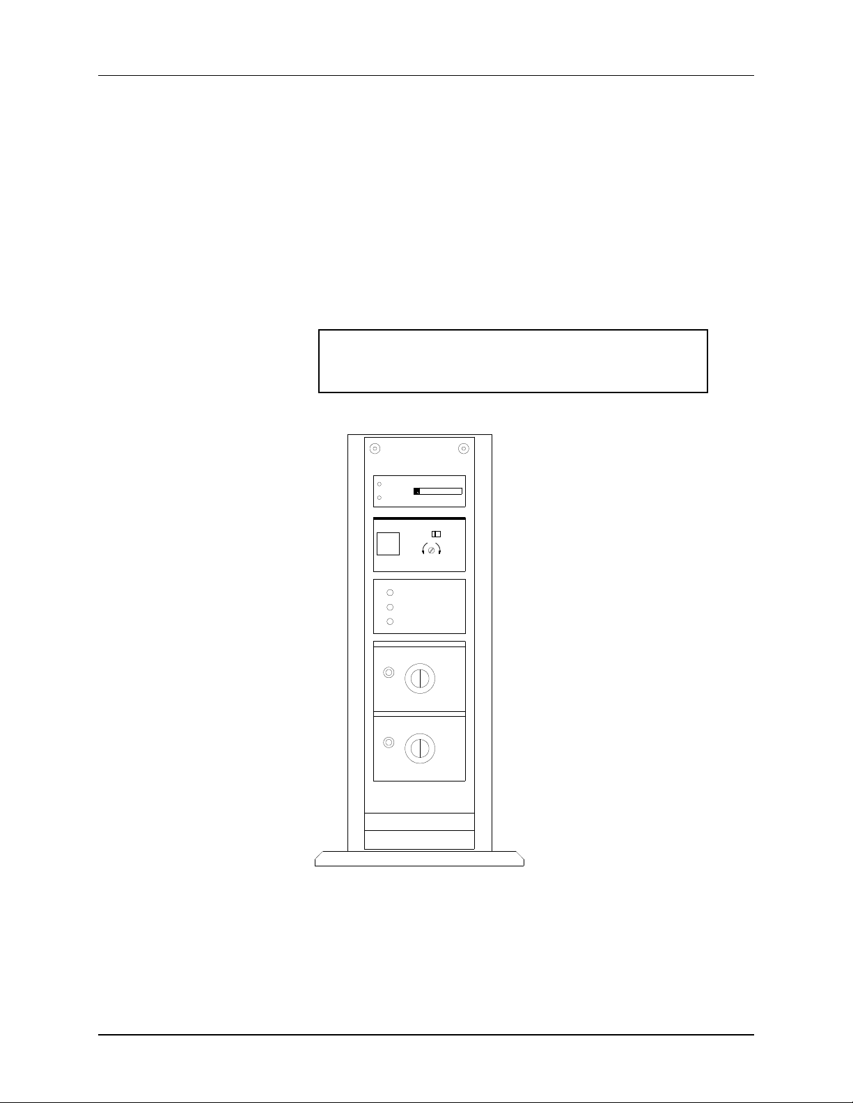
Ultra Sonic Power Supply
Caution
Only qualified technicians should service the power supply.
The ultrasonic attachment is made up of several components. They are the
power supply, the horn assembly and the connecting cable. In addition there is a
knife assembly with a changeable tool steel blade.
The power supply should be located next to the SS Finisher. This unit generates
electrical pulses at 35 KHz to the converter. All guards must be closed for the
Sonics to be activated. The power supply contains a "TEST" button, power
indicator light, Auto/MAN switch, Cutting and US-Time controls and a relative
power gauge.
NOTE: The power supply is adjusted for proper operation at the
factory. DO NOT change any of the adjustments on the power
supply.
TELESONIC
ULTRASONICS
TEST
LOAD
2
20
10
50
100
10
AUTO MAIN
TEST
TUNING
OVERLOAD
OVERTEMP
POWER
CUTTING-CONTROL
1
0
1
2
3
10
4
9
100
200
US-TIME
10
9
8
MS
100
8
MS
5
6
7
0
1
2
3
4
5
6
7
SG3510 CT
The Ultrasonic Power Supply is pre-programmed for the correct settings at the
factory. The following instructions describe how to check and change these
settings.
Users Manual SS Finisher Operation •••• 11
Page 12

IMPORTANT: FOR PROPER OPERATION, USE THE FACTORY
SETTINGS AT ALL TIMES. CHANGING THESE SETTINGS MAY
RENDER THE SONIC KNIFE INOPERABLE, REDUCE THE
QUALITY OF THE CUT AND/OR REDUCE THE RELIABILITY
OF THE SONIC KNIFE.
Settings
The Power Supply is set properly at the factory. Any changes to the factory
setting may result in improper operation. If necessary, the factory settings may
be restored as follows:
AUTO/MAN switch AUTO
CUTTING CONTROL 0
US-TIME 0
COAXIAL CONVERTER
CABLE
37 PIN CONNECTOR
AC POWER CABLE
Test Button
The "Test" button can be used to check the operation of the sonic stack
assembly. This is done by depressing the switch while observing the power
indicator. If more than 2 bars are illuminated, the stack requires repair.
AUTO/MAN Switch
The AUTO/MAN switch should always be in the AUTO position.
CUTTING-CONTROL and US-TIME Controls
The CUTTING-CONTROL and US-TIME Controls should always be set to 0.
Users Manual SS Finisher Operation •••• 12
Page 13

Power
"Power" on pilot light indicates when the power supply is on. This only indicates
that the power supply is connected to the line power. Ultrasonic energy is only
generated during the actual cut cycle. This is indicated by the green light next to
the US_TIME control.
Connecting the Ultrasonic Power Supply
Line Cord
Plug the line cord into the mating receptacle on the back of the power supply and
secure it with the metal bail. Plug the other end of the line cord into the line
(mains) receptacle.
NOTE: The Ultrasonic Power Supply does not have a power switch. It is
on all the time. Ultrasonic energy is only generated during the cut cycle.
Sonic Stack Cable
The Sonic Stack Cable plugs into the mating connector on the rear of the Power
Supply. Insert the plug firmly into the socket until it is fully seated.
Power Supply Control Cable
The Power Supply Control Cable plugs into the 37-pin connector on the rear of
the Power Supply. Plug in the cable and secure with the retaining screws.
Users Manual SS Finisher Operation •••• 13
Page 14
Loading the Machine
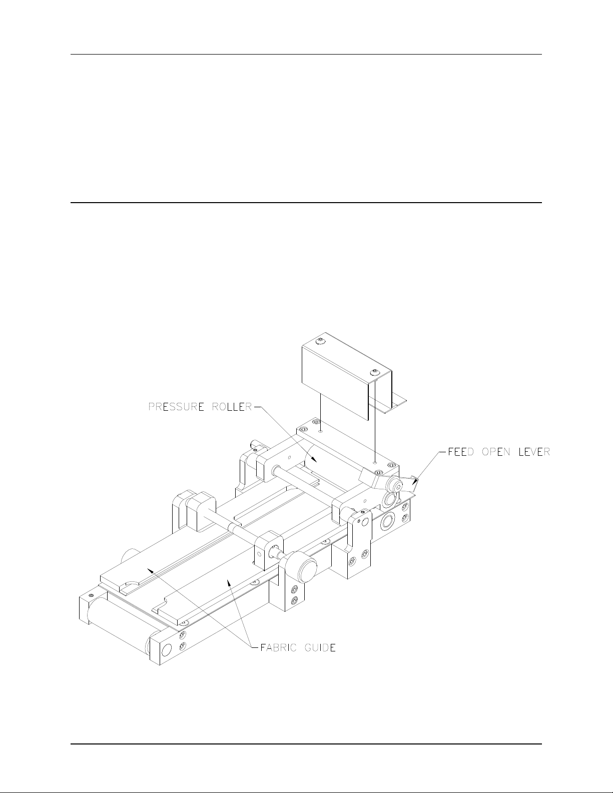
Loading the Tape
To load the SS Finisher, start by adjusting the Fabric Guides to the correct
width, allow the fabric to slide between them without buckling. Be sure to adjust
the guides evenly on both sides, as the SS Finisher must be run with the fabric
centered in the machine. Adjust the Fabric Guide Bar Adjust so that it centers
the Guide Bar over the fabric.
Pressure Roller
Pressure Roller Setting
The Feed Pressure roller is Spring loaded, so there is always pressure to the
drive roller. The feed roller can be opened by moving the Feed Open lever to
the vertical position, and then lowering it when ready to operate the machine.
(Shown with the Fabric Stripper Blade removed)
Users Manual SS Finisher Operation •••• 14
Page 15
Ultra Sonic Horn "Stack"
Cutter Set-up
The "Converter / Horn" assembly is called the "Stack". The stack generates the
ultrasonic energy that cuts and fuses the fabric.
The converter receives the electrical pulses from the power supply and converts
them to mechanical lineal motion. This motion is then amplified as it goes
through the “Horn”. This causes the horn to vibrate at 35 KHz acting like a tiny
impact hammer. This action causes friction heat that cuts and fuses the label
tape.
CAUTION: The horn can cause burns if touched during operation
The SS Finisher has been set-up at the factory to run a checkout stock as the
minimum checkout requirement. Depending on the shipping destination and the
information supplied to the factory, the actual production job the customer has
ordered will be tested.
At times the unit will require adjustment and maintenance. The top knife will
need to be replaced and squared, the stack will also need to be adjusted to cut in
a new location, and general tuning will need to be done to keep the SS Finisher
in top running condition. The following sections are in order of procedure to
set-up the knife and to keep the SS Finisher cutting properly.
Remove Front Cover to Make Adjustments
FRONT COVER
Users Manual SS Finisher Operation •••• 15
Page 16
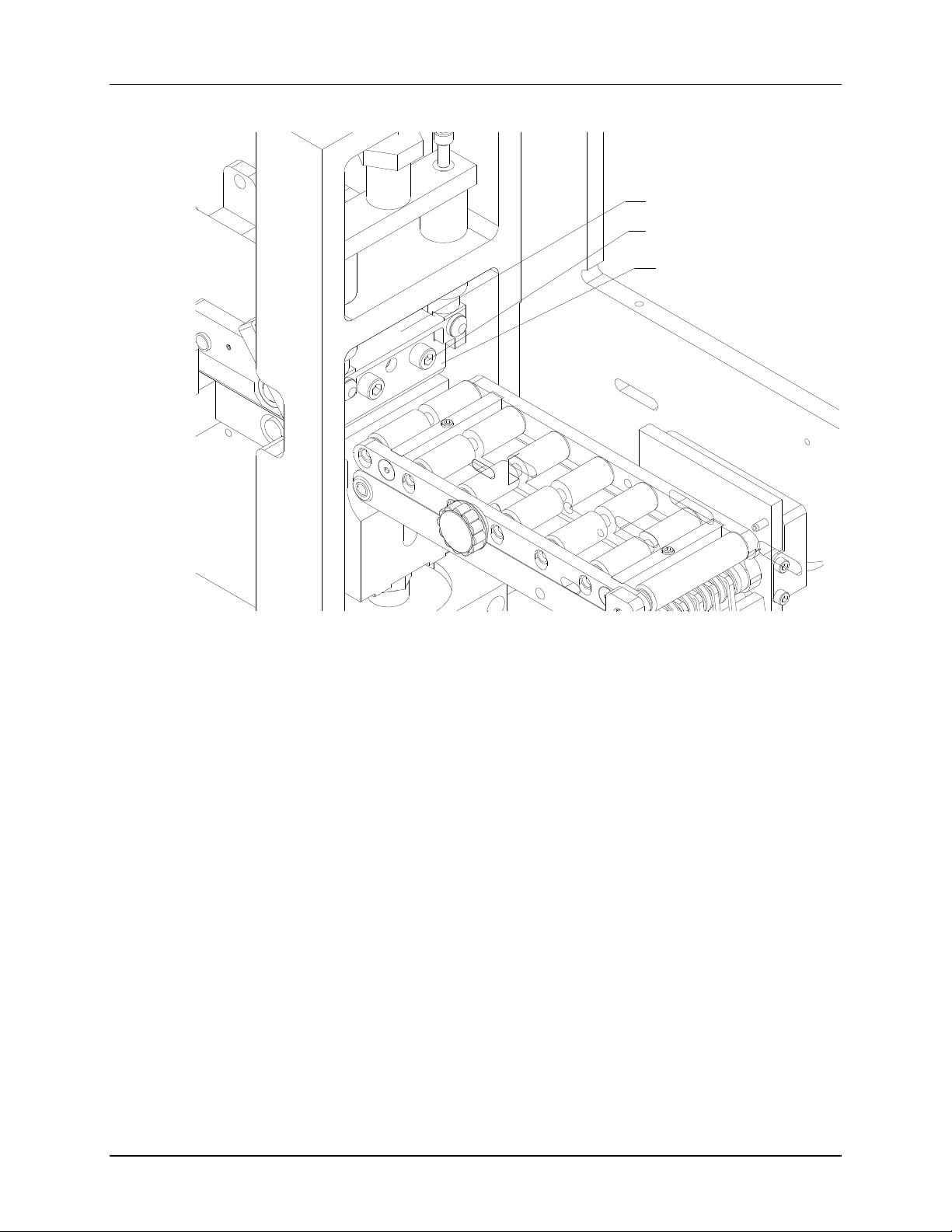
Squaring the Horn to the Blade
ROTATE
To square the Horn to the Blade, first loosen the four square adjusting cap
screws, shown above. This will allow the stack to rotate. Next loosen the two
adjusting cap screws shown below. Once they are loose, place a 3/16 ball driver
next to the deck and slide entire stack against the ball driver. This will square
the horn to the deck. Next, tighten the four square adjusting screws. Once they
are tight, return stack to the center of the blade by turning the screw adjustment,
and then tighten the two adjusting cap screws.
Users Manual SS Finisher Operation •••• 16
Page 17

Ground Detection Sonic Cutter
The SS Finisher has a Ground Detect Circuit that turns the sonic power off after
the blade has cut through the fabric. This reduces blade wear and increases the
life and reliability of the blade.
The blade holder and blade is electrically isolated from the frame of the
machine. A wire is attached to the blade holder. A circuit looks to see when the
blade comes in contact with the horn surface and shuts down the sonic power
source.
Users Manual SS Finisher Operation •••• 17
Page 18
Replacing the Top Knife Blade
KNIFE BLADE MOUNT
LEVELING SCREWS
KNIFE BLADE
Overview:
Upper blade wear is caused by the abrasion from the ultrasonic vibration when
the horn face and the edge of the blade are in contact. There are four major
adjustments that control the life of the upper blade. The first is a properly tuned
power supply. Second is the blade parallel the horn face. Third is the amount of
pressure between the blade and the horn (factory setting .750”). Fourth is the
dwell time between the blade edge and the horn face after the cut has been made
(factory setting .015”). The following is a guide to properly replace the upper
knife blade.
Note:
When removing the knife blade, the blade may seem tightly mounted to the knife
mount pin. Pull blade off of mount pin by pulling from the top of the blade.
Users Manual SS Finisher Operation •••• 18
Page 19
Leveling the Top Blade
CAUTION: Turn off the power to the power supply only.
Remove the material from the horn and knife blade area. Use a 5/32” “T”handle or Allen wrench to loosen the two leveling screws located each side of
the pivot pin on the knife blade holder. Jog the machine with the START/TEST
buttons to bring the blade to the horn surface under full pressure. Evenly tighten
the two leveling screws located each side of the pivot pin on the knife blade
holder.
Turn the sonic power supply back on. Cut some fabric to determine if the blade
is level. If not level – repeat the above procedure.
Adjusting Knife Spring Pressure:
The .750 gap setting shown below – under “Knife Pressure” - is the initial
starting point for a new knife blade. As the knife begins to show intermittent
labels not being cut clean then an adjustment is needed to the spring pressure.
If the knife is not cutting the label clean and delivering a cut single label to the
stacker then the knife should be checked for level (see leveling procedure).
Never pull the labels apart to use them as they can fray when washed. If no
improvement is seen, make sure the “Lock Knob” is tight, then increase the
pressure one flat on the adjusting nut. If no improvement is seen then increase
one more flat of the adjusting nut. This procedure can be repeated several times
during the life of the upper blade until the pressure will no longer cut. At this
point the pressure is greater than the power of the Sonics and will stall the horn,
replace the blade.
Note: Bring the Adjusting Nut back to the .750” gap setting whenever a
new blade is installed.
LOCK KNOB
ADJUSTING NUT
SPRING
KNIFE BLADE
Users Manual SS Finisher Operation •••• 19
Page 20
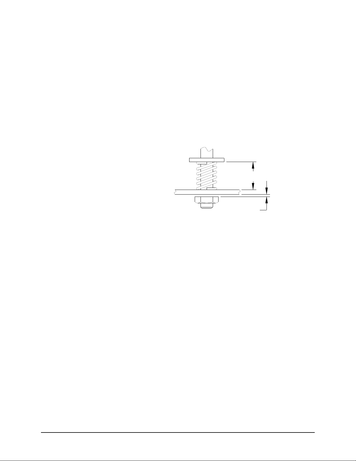
Knife Pressure
This new design comes with factory set knife pressure. The following diagram
shows the factory settings for pressure with a new top blade. Should the unit
stop cutting, the knife blade should be leveled first, and if unsuccessful, add
pressure with the “Adjusting Knife Spring Pressure” instructions above.
A means to adjust this pressure is built into the knife linkage. To make this
adjustment, first the .015” gap must be set - followed by the .750” gap.
To set the .015” gap, jog the machine until the knife blade is in its full down
position with no fabric under the blade. Loosen the LOCK KNOB and turn the
ADJUSTMENT NUT until the gap is at .015”. Retighten the LOCK KNOB.
To set the .750” gap, jog the machine until the knife blade is in its full down
position with no fabric under the blade. Loosen the screw on the ADJUSTING
NUT; turn the ADJUSTMENT NUT until the gap is .750”. Tighten the
setscrew.
.750
.015
START & OPERATION
POSITION
Replacing the Top Blade
Turn the Ultrasonic power supply switch off.
Note: The knife button and start button combination will cycle the blade ½
revolution - from no pressure to full pressure.
Because the knife blade will eventually wear from abrasion caused by ultrasonic
vibration when the horn face and the knife blade are in contact, the knife blade
will need to be replaced periodically.
To replace the knife blade, remove the knife blade guard. The knife is attached
to a self-leveling mount with a leveling pin. Loosen and remove the (2) knife
screws and remove the blade from the leveling pin. Replace the new knife blade.
Thread the (2) knife screws into the knife mount but do not tighten. The blade
must be leveled each time it is replaced. See below for knife blade leveling
procedure.
When removing the knife blade, the blade may seem tightly mounted to the knife
mount pin. Pull blade off of mount (leveling) pin by pulling from the top of the
blade.
Knife Blade leveling
Jog the knife with the TEST/START buttons until the blade is in full contact
with the horn. Tighten the two clamp screws in small equal increments until
they are very tight. Loose screws will shorten blade and horn life. (A loose
screw may cause the blade to make a noise during the cut.)
Users Manual SS Finisher Operation •••• 20
Page 21

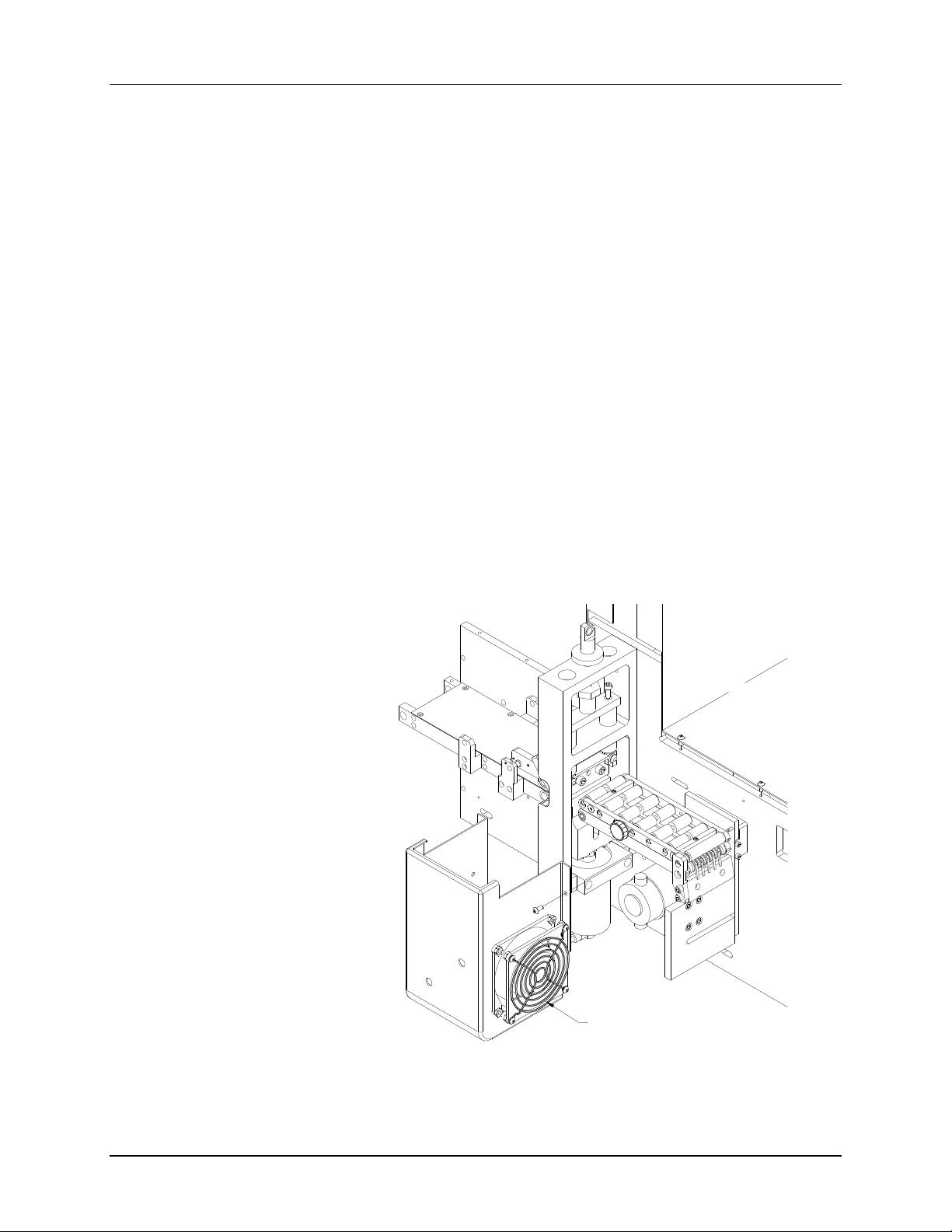
Horn Replacement
1. Remove the outfeed Conveyor Assembly by loosening the mount screws
located inside the machine, behind the machine upright plate.
2. Make sure to save the spacers that mount the outfeed Conveyor Assembly
away from the upright.
3. Removed the sonic mounting bracket by loosening the mounting bracket
screws.
4. Remove the sonic stack and replace with a new, or rebuilt sonic stack
assembly.
5. Install components in reverse order.
1000W SONIC STACK
MOUNT SCREWS
SPACERS
SONIC MOUNTING BRACKET
CONVEYOR ASSEMBLY
Users Manual SS Finisher Operation •••• 21
Page 22

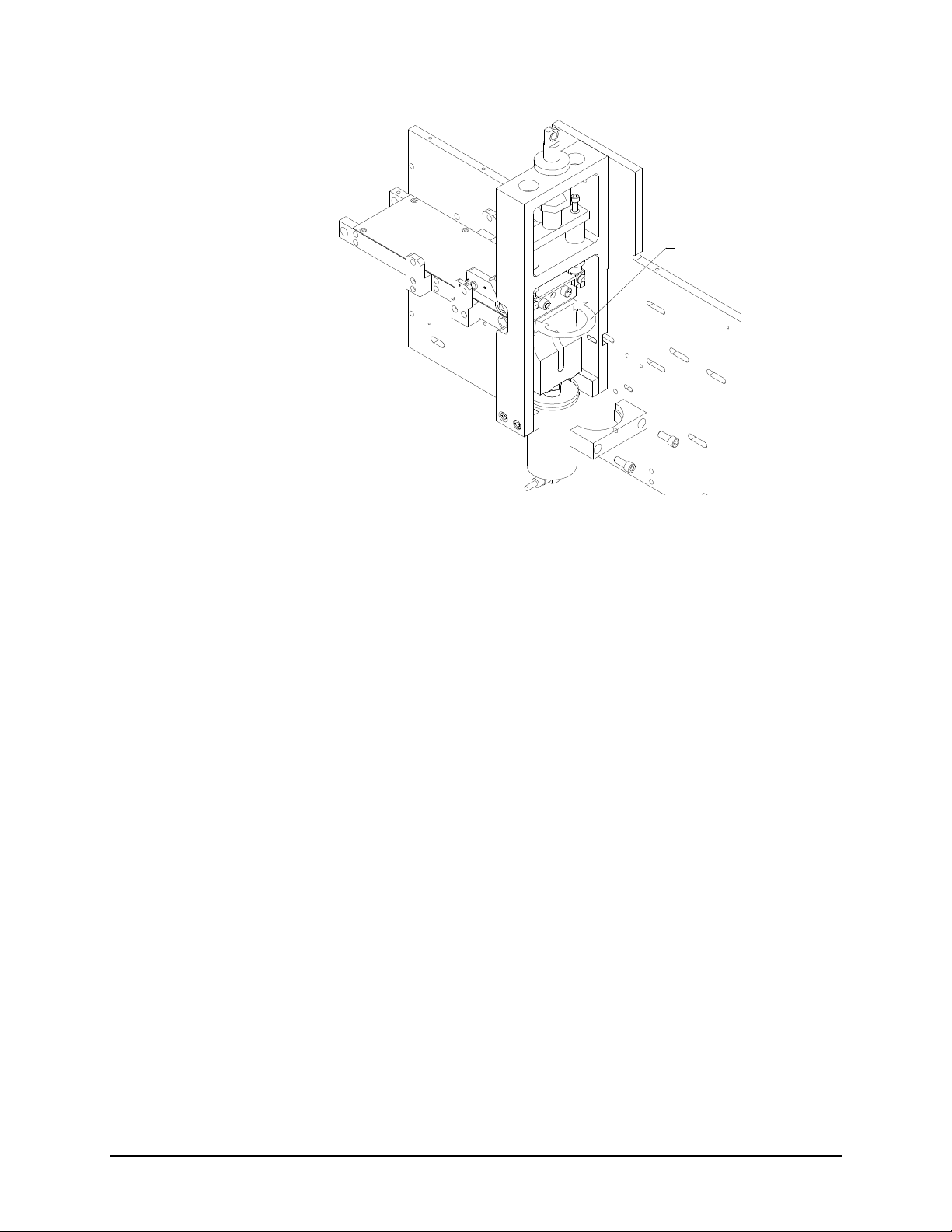
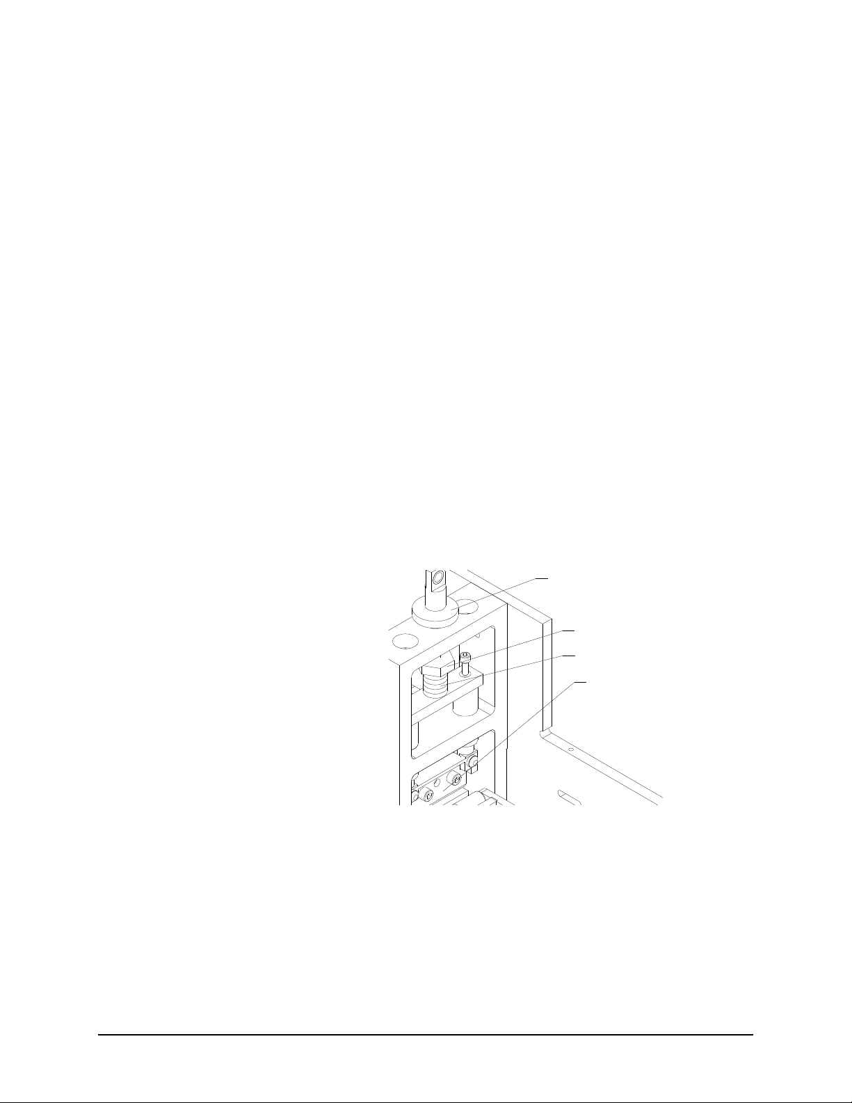
Proximity Switch Adjustment
The Proximity Switch triggers the Ultrasonic Power Supply to begin generating
Ultrasonic energy during the cut. If the Proximity switch is not adjusted
properly, the Power Supply will not be triggered and the unit will not cut.
The Proximity Sensor Flag (see illustrations below) should be adjusted as
shown. The flag should be positioned so that there is a 0.015” (0.4mm) gap
between the Flag and the face of the Switch. And, in the home position, the
proximity flag should be approximately 25 degrees above the proximity sensor.
PROXIMITY
SWITCH
PROXIMITY SWITCH
FLAG
Note: Above view is looking down on top of machine.
PROXIMITY SENSOR
PROXIMITY FLAG
Note: Above view is looking at flag and sensor toward exit conveyor side of
machine.
Users Manual SS Finisher Operation •••• 22
Page 23

Trouble Shooting
Ultrasonic Noise
Since ultrasonics is high frequency sound, some noise will be heard as it makes
its cut. It is recommended that people in the immediate area wear ear protection.
The noise can be minimized by making some of the following adjustments:
Cause
Bridge blade or other metal
hitting horn
A component of the stack loose Check all parts including clamps and
Blade is loose in the sandwich Check by trying to slide the blade
Too much dwell of the blade Re-adjust the upper blade. See
Carbide on horn may be loose Replace horn
Blade is not square to the horn face Re-adjust the upper blade. See
Blade not parallel to horn face. Re-adjust the upper blade. See
Maintain .015” clearance around horn
the screws holding the stack to the
machine.
endwise in the sandwich. If the blade
slides - try tightening the sandwich
screws to increase the clamp pressure.
procedure in Blade Replacement
procedure in Blade Replacement
procedure in Blade Replacement
Solution
Users Manual SS Finisher Trouble Shooting •••• 23
Page 24

Sonic Troubleshooting
(See Section 4-5 of Branson Manual)
Problem Probable Cause Remedy
A - Sonics are not working and
power supply light is off.
2 – On / Off switch in “off”
3 – Power lamp bulb burned out 3 – The lamp could be off but power supply
4 - Interface cable not plugged in 4 – Check interface cable between power
B - Sonic power supply is on but
no vibration is felt at the
converter in test mode.
2 - Converter is bad. 2 – Replace the stack assembly
3 - Horn is bad. 3 – Replace the stack assembly
4 - Power supply is bad. 4 – Replace power supply –
5 - Horn assembly not connected
C - Fabric cut is indented - but
not severed in two.
1 – Blown fuse 1 – Replace fuse on back end of power
supply.
2 – Move switch to “on” position
position
cooling fan is running. Unit is OK to
operate.
supply and SS Finisher
1 - Cable to converter is bad. 1 – Replace the stack assembly.
Return for rebuilding
5 – Check connection
to power supply
1 - Improper power setting 1 – Turn on power supply – check all
connections
2 - Power supply not turned on 2 – Turn on power supply
3 - Knife has become dull 3 – Change knife blade insert.
D - Fabric cuts on only one side. 1 - Knife anvil is not parallel with
the horn.
Users Manual SS Finisher Trouble Shooting •••• 24
1 – See knife-leveling procedure in the blade
replacement section.
Page 25

Control Panel Operation
COUNTER 999999 STOPPED
SS Finisher Controls
LEN:XXXmm CUT: SPD:
Start
- Starts the SS Finisher
Feed
Knife
Stop
- ON LINE light must be GREEN
(SS Finisher waiting for material to cut)
- FEED and START must both be used
- Feed will stop when the buttons are released
- Stock moves through in one continuous strip
- Stock moves through without cutting
- KNIFE and START must both be used
- Knife movement will stop when the buttons are released
- The upper knife will move slowly towards the horn face. Machine
will make a ticking sound.
- Allows the operator to visually see the gap between the knife and
the horn face. – Make rough knife leveling adjustments.
- The stop button will stop the cutter at the end of the current label
being sensed.
Users Manual SS Finisher Trouble Shooting •••• 25
Page 26

Indicator Lights
The AVERY DENNISON SS Finisher has three Indicator lights. These lights
are used along with the LCD display to tell the operator the current status of the
SS Finisher.
On Line
OFF
- Has not been powered on.
- Is in its power - up sequence.
- Failed the system test
ORANGE
GREEN
Sensor
GREEN
Error
ORANGE
- Passed system test
- Ready for operation.
- Start button has been pressed - SS Finisher running
- Accumulator waiting for material.
- SS Finisher is stopped - light is on - sensor is positioned over a
sense mark
- Flashing light while SS Finisher is running - the sensor is in line
with the sense marks. See Color Mark Sensor Adjustment
- System inter-lock triggered, see display for error.
- See Appendix B - Error Messages
Users Manual SS Finisher Trouble Shooting •••• 26
Page 27

Instrument Panel
COUNTER 999999 STOPPED
LEN:XXXmm CUT: SPD:
Single Screen Input
Overview
The display has only three operator-input fields displayed at all times. The left
two gray keys at the bottom of the display control the cut length in millimeters.
The next two buttons adjust the cut position and the last button is speed. The
speed selection has little impact on machine throughput.
Feed Length
To enter the proper label feed length - measure the label desired to be cut from
one registration mark to the exact same place on the next registration mark as
illustrated below. The feed length should be set to 76mm.
COPY AREA COPY AR
2010 4030 706050 9080 140110100 130120
Users Manual SS Finisher Trouble Shooting •••• 27
FEED
The feed length may have a value from 25mm to 129mm. Use the arrow keys to
increase or decrease the displayed value. The value will change in single
millimeter increments by holding the button or single button pulses. The value
that is displayed will be the new length - no save or enter key is required.
Page 28

Position the label registration mark so that the green light beam from the sensor
is just to the right of the registration mark. The light should be in a blank area of
the label in the feed direction. This should be done manually.
Cut Position
When the desired feed length has been selected, start the printer and run labels
into the stacker. After two or three labels have fallen into the stacker - stop the
printer and remove the top label. Measure the distance from the end of the label
to the desired cut location. Add or subtract the value from the value displayed.
DO NOT input the value, it must be added to or subtracted from the current
value. The maximum value is ± the label length from zero. The cut value
cannot be greater than the label length. The cut number for the label illustrated
below should be decreased by 19mm to cut in the center of the registration mark.
COPY AREA
FEED
Use the arrow keys to increase or decrease the displayed value. The value
will change in single millimeter increment by holding the button or single button
pulses. The value that is displayed will be the new length, no save key is
required.
10 20 30 40 50 60
70
80
Users Manual SS Finisher Trouble Shooting •••• 28
Page 29

Color Mark Sensor Adjustment
Contrast Sensor
2/99 REV. 0
(Blue Frame w/ Adjustment Pot on /Sensor)
Overview
The sensor is designed to register off a preprinted mark on a label. The label
must have a no copy area measuring 7.8mm in the feed direction prior to the
registration mark. The registration mark is to measure 3mm in the feed direction
and 10mm across the web. The registration mark must be a solid bar. The
registration mark may be any color except yellow or green.
Mount Screws
Location Clamp Screw
Trim Pot
Amber Light
Sensor Foot
Setup
Place a strip of the desired printed material through the web guides on the feed
deck under the registration sensor and through the open feed roller. There must
not be any drag from the web guides or the foot on the registration sensor. If
there is drag from the web guides open them equal distance so the web tracks
down the center of the feed deck. If the foot on the sensor contacts the web
make sure the “Locating Clamp Screw” is snug. If this doesn't correct the drag,
loosen the two “Mount Screws” that mount the sensor bracket to the upright
frame. Insert a .015" shim or 3 layers of material between the feed deck and the
“Sensor Foot”. Retighten the two “Mount Screw” and remove the spacing
material. If the foot drags on the web this will steer the web off center and not
track correctly through the feed roller.
Turn on the Finishing Station. Loosen the “Location Clamp Screw” and place
the green light beam in line with the registration mark on the label in the feed
direction. Advance the web by hand with the feed open until the green sensor
light is positioned just prior to the label registration mark. With the green light
Users Manual SS Finisher Trouble Shooting •••• 29
Page 30

LCD Display
setting on blank material, turn the “Trim Pot” counterclockwise until the “Amber
Light” below the “Trim Pot” goes out. Slowly turn the “Trim Pot” clockwise
until the “Amber Light” comes back on. Move the web until the green light
beam sets directly over the registration mark and the “Amber Light” should go
out. If the “Amber Light” stays on - rotate the “Trim Pot” counterclockwise
until it goes out. Move the web slightly left to right by hand so the green light
moves from the registration mark to blank material and watch the “Amber
Light”. The light should quickly flash on and off. If the “Amber Light” is slow
to react turn the “Trim Pot” 1/8 turn clockwise and retest until the light toggles
quickly.
The LCD display is a 2 line, 24 character, with back lighting feature for easy
readability. The first line of the display in most cases will be a prompt or
question. The second line is the response to the prompt or question.
Diagnostic Tests
During power up the following tests and screens will be displayed.
DIAGNOSTIC TEST 1
This screen is displayed during the
This screen will be displayed while the Front Panel is initializing and waiting for
the MIB response.
The code will check the functionality of the LED's and the display. Each state of
the LED's will be checked - (red, green, amber and off). The code will check the
LCD display by writing a character to the display, checking for communications
and then reading the character back and comparing with the code. If an error
occurs, the code will halt the diagnostic test and blink the ERROR LED.
The keypad is also checked during DIAGNOSTIC TEST 1. Each key is tested
to see if it is stuck on. If a fault condition is detected, the test is halted and the
screen will display the first error key found with the following display:
(BUTTON NAME) KEY STUCK
DIAGNOSTIC TEST 1
The (BUTTON NAME) will be one of the push button names on the front panel
- START, FEED, TEST, STOP, EXIT, MODE, <YES, NO>, OR ENTER.
When the code has finished the above tests, the code will attempt to
communicate with the 196 Machine Control Board (MIB). If all tests are
complete and no errors detected, then the system will go to the HOME screen.
Control Panel
test.
Users Manual SS Finisher Trouble Shooting •••• 30
Page 31

Recommended Spare Parts:
Qty. Part #
1 571151 Power Supply, 1000w 115v
1 356026 Timing Belt 1/5P 57T
1 571157 Sonic Horn Stack
1 424017 Roller – Molded Urethane
2 424020 Timing Belt 1/5P 52T
5 577056 Knife Blade
1 921168 Fuse - 10A, 5x20mm
4 990080 10:32 x 3/8” Cap Screw
7 991028 “O” Ring Drive Belt
1 990755 Fuse - 1.0A 250V time delay
1 990759 Fuse - 2.0A 250V time delay
1 990765 Fuse - 4.0A 250V time delay
Qty. Part #
Description (115 Volt Machine) – Kit Number 420009
Description (230 Volt Machine) – Kit Number 420010
1 571155 Power Supply , 1000w 230v
1 356026 Timing Belt 1/5P 57T
1 571157 Sonic Horn Stack
1 424017 Roller - Molded Urethane
2 424020 Timing Belt 1/5P 52T
5 577056 Knife Blade
2 990669 Fuse - 5.0A 250V time delay
4 990080 10:32 x 3/8” Cap Screw
7 991028 “O” Ring Drive Belt
1 990755 Fuse, 1.0A 250V time delay
1 990759 Fuse, 2.0A 250V time delay
1 990777 Fuse, 0.5A 250V time delay
Users Manual SS Finisher Trouble Shooting •••• 31
Page 32

Troubleshooting Electrical
Power Up / Sign On Communications
Problem Probable Cause Remedy
A - Machine fails to power up 1 – Incorrect power amplitude 1 - Confirm that the AC entry is configured for the
line voltage intended to be applied to the
machine. Failure to do so can damage the
machine’s internal power supply. Refer to the
“Fuse Configuration”
2 – Lack of power to the machine 2 - Check that both ends of the power cord are
securely plugged in.
2A - Confirm that the outlet the machine is plugged
into has power.
3 – Missing or blown fuse(s) 3 - Check that the fuse(s) located inside the AC
entry are present and intact. Replace as needed.
Refer to the Fuse Configuration.
4 – Unconnected cable / connector
inside machine.
B - Front panel displays no
text or nothing at all
C - Front panel does not
complete diagnostic test 1.
D - Stock does not advance
when the start button is
pressed.
2 – Tag length or Offset values are
3 – Feed motor unplugged or faulty 3 - Check feed motor cable and/or replace feed
4 – Feed roller not gripping stock 4 - Adjust feed pressure. Refer to “Mechanical
5 – Feed rollers bound 5 - With power off, check that all rollers turn freely.
6 – Stock Bound 6 - Check that stock will pull through the printer
E - The Stacker fails to run. 1- The stacker cable is not
2 – Faulty Stacker Motor 2 - Replace Stacker Motor.
3 – Stacker jammed. 3 - Remove cause of the jam at the stacker.
1 – Front panel cable unplugged. 1 - Power off and remove the power cord from the
1 – Front panel board unplugged
from the main board.
1 – An interlock condition exists. 1 - Determine the number and type of interlock(s)
invalid.
connected
4 - Power off and remove the power cord from the
AC entry. Remove the back cover and inspect
the cables and connectors to and from the power
supply. Refer to the “Electrical System
Schematic”.
AC entry. Remove the back cover and inspect
the cables and connectors to and from the front
panel. Refer to the “Electrical System
Schematic”.
1 - Power off and remove the power cord from the
AC entry. Remove the back cover and check
connectors.
by reading the front panel display. As each is
corrected, the number of errors will decrease.
2 - Check values located in front panel and adjust.
motor.
Adjustment of Feed Roller Pressure”.
with little or no resistance.
1 - Power off and remove the power cord from the
AC entry. Remove the back cover and inspect
the cables and connectors.
Users Manual SS Finisher Trouble Shooting •••• 32
Page 33

Appendix A
Manufactures of Hearing Protectors
AMERICAN OPTICAL COMPANY
Department 4041
Safety Division, 14 Mechanic Street
Southbridge, MA 01550
BILSON INTERNATIONAL, INC.
109 Carpenter Drive
Sterling, VA 22170
E-A-R
A Division of the CABOT CORPORATION
7911 Zionsville Road
Indianapolis, IN 46268
FLENTS PRODUCTS COMPANY, INC.
Ely Industrial Part, Building #2
Norwalk, CT 06854
GLENDALE PROTECTIVE TECHNOLOGY, INC.
130 Crossways Park Drive
Woodbury, L.I., NY 11797
SELLSTROM MANUFACTURING COMPANY
Sellstrom Industrial Park
220 South Hicks Road, Box 355
Palatine, IL 60067
Users Manual SS Finisher Appendix A •••• 33
Page 34

Appendix B
Error Messages
When the SS Finisher detects an error condition, the display will show the last
error encountered. When the last error is removed – the display will show
previous errors – if they exist.
When the machine is first powered on, the front panel will display the following
screen;
D I A G N O S T I C T E S T 1
If the front panel display remains in this condition – it is indicating a failure to
communicate from the front panel to the motherboard. Check connections to the
motherboard.
When the machine has successfully completed initializing, the front panel will
display one of the following two screens;
C O U N T E R 9 9 9 9 9 9 R E A D Y
L E N : X X X M M C U T : X X X S P D :
C O U N T E R 9 9 9 9 9 9 S T O P P E D
L E N : X X X M M C U T : X X X S P D :
OR
If the length of the label is not set correctly or there is a problem with the feed
mechanism – the machine will not operate and the following error message will
be displayed;
A L I G N S T O C K
L E N : X X X M M C U T : X X X S P D :
If the guard door is open or if there is a faulty interlock switch – the machine will
not operate and the following message will be displayed;
C L O S E G U A R D
L E N : X X X M M C U T : X X X S P D :
Users Manual SS Finisher Appendix B •••• 34
Page 35

Appendix C
Label / Machine Speed
The SS Finisher is capable of producing labels from 25mm to 259mm in length.
Not all AVERY DENNISON printers will slow down sufficiently to produce the
minimum feed so the SS Finisher will not fall behind creating a loop of material
between the two products. AVERY DENNISON 6500 and 642 printers will run
at the slower speeds labeled as “False”. AVERY DENNISON 636, 656, 676
and SNAP printers will slow down to 3” per second minimum feed rate. Use the
chart below to make the proper format speed selection for the desired printer
636 and 656 printer speeds: 3”/sec, 4.5”/sec, 6”/sec and 7”/sec.
676 and 676LKP printer speeds: 3”/sec, 4”/sec and 5”/sec.
SNAP printer speeds: 3”/sec, 4.5”/sec, 6”/sec and 7”/sec.
Note:
If running a SS Finishing Station with a LOKPRINT System –
run above 5” per second. The label will not be finished properly and
may not hold up in the application.
Print Speed Minimum Length
3 IPS 1” (25 mm)
4 IPS 1.6” (40 mm)
4.5 IPS 1.7” (42mm)
5 IPS 2” (52mm)
6 IPS 2.3” (58mm)
7 IPS 2.8” (70mm)
DO NOT
Users Manual SS Finisher Appendix C •••• 35
Page 36

Labels Rate Chart
Machine Speed in Inches per Second
LABEL LENGTH 2 IPS 3 IPS 4 IPS 4.5 IPS 5 IPS 6 IPS 7 IPS
1.0” (25mm) 122 FALSE FALSE FALSE FALSE FALSE FALSE
1.2” (30mm) 102 FALSE FALSE FALSE FALSE FALSE FALSE
1.4” (35mm) 87 131 FALSE FALSE FALSE FALSE FALSE
1.6” (40mm) 76 114 FALSE FALSE FALSE FALSE FALSE
1.8” (45mm) 68 102 FALSE FALSE FALSE FALSE FALSE
2.0” (50mm) 61 91 122 FALSE FALSE FALSE FALSE
2.2” (55mm) 55 83 111 125 FALSE FALSE FALSE
2.4” (60mm) 51 76 102 114 FALSE FALSE FALSE
2.6” (65mm) 47 70 94 106 117 FALSE FALSE
2.8” (70mm) 44 65 87 98 109 FALSE FALSE
3.0” (75mm) 41 61 81 91 102 FALSE FALSE
3.2” (80mm) 38 57 76 86 95 114 FALSE
3.4” (85mm) 36 54 72 81 90 108 FALSE
3.5” (90mm) 34 51 68 76 85 102 FALSE
3.7” (95mm) 32 48 64 72 80 96 FALSE
4.0” (100mm) 30 46 61 69 76 91 107
4.1” (105mm) 29 44 58 65 73 87 102
4.3” (110mm) 28 42 55 62 69 83 97
4.5” (115mm) 27 40 53 60 66 80 93
4.7” (120mm) 25 38 51 57 64 76 89
5.0” (125mm) 24 37 49 55 61 73 85
5.1” (130mm) 23 35 47 53 59 70 82
How to Use Chart:
•
Locate the desired label length or next highest length shown in the left hand
column.
•
Move across the top of the page to the desired speed
•
Move down the column and match the label length selected
•
This is the estimated labels per minute rate the SS Finisher will produce.
All marginal size labels must be tested with the desired format.
•
If the speed selected is listed as “False” move to the next slower speed
available.
•
Any speed between the “False” rate and the next highest allowed speed
MAY run but must be tested on the desired format.
Users Manual SS Finisher Appendix C •••• 36
Page 37

Appendix D
Multi Color Contrast Sensor Installation Instructions
Sensor Installation - Option No. 420014
1. Disconnect sensor cable from existing sensor.
2. Cut sensor cable tie holding the sensor cable to the tie holder attached to the
frame.
3. Remove existing sensor mount bracket. Retain the mounting hardware. (2
#8-32 SHCS and 2 # 8 flat washers)
4. Fasten Item 5 (Bracket, Sensor Mtg.) to the frame using the saved hardware.
5. Assemble Items 1, 2, 3 and 4 (Sensor, Bracket Guide, Sensor Slide and #10
Screws Respectively) as shown in the attached catalog pages.
6. Align Item 3 (Sensor Slide) with slot in Item 5 (Bracket, Sensor Mtg.) and
install Items 6, 7 and 8 (#10 Flat Washer, #10 SHCS x 3/8” and Thumbscrew
Knob).
7. Replace existing cable with new cable (421142 supplied). Replace all cable
ties.
8. Connect the sensor cable to the Sensor. Position the sensor to its farthest
position.
9. Cable tie sensor cable to the tie holder attached to the frame
Users Manual SS Finisher Appendix D •••• 37
Page 38

Teach-in Procedure:
1. Turn the selector switch (Arrow) to the “Q1” setting.
2. Place the material under the light spot just
3. Press and
4. Move the sense mark under the light spot.
5. Release the “Teach” button.
6. Turn the selector switch (Arrow) to the “RUN” position.
7. The “Q/ok” light will flash when the sense mark is moved under the light spot.
hold
the “Teach” button.
T
ON
eac
before
the sense mark.
h
RUN
DELAY
Q1
Q/ok
RUN
Notes:
The switching threshold is set in the middle between the received signals from
the background and the mark and is stored permanently. The optimal sender
light color is selected automatically.
If the teach-in procedure was not successful, the “Q/ok” light will flash
continuously.
Users Manual SS Finisher Appendix D •••• 38
Page 39

Color Contrast Sensor Option Assembly
Color Contrast Sensor Option Parts List
Item Part # Description Qty
1 421138 Sensor, Multi color 1
2 421141 Bracket, Guide, Sensor 1
3 421139 Bracket, Sensor slide 1
4 991140 M5 x 10mm Flat head SHCS 4
5 421140 Bracket Sensor mtg. 1
6 990144 # 10 Flat washer 1
7 990080 # 10 SHCS x 3/8 1
8 990313 # 10 Thumb screw knob 1
9 421142 Cable, Color sensor 1
Users Manual SS Finisher Appendix D •••• 39
Page 40

Users Manual SS Finisher Appendix D •••• 40
Page 41

Electrical Schematic
Users Manual SS Finisher Electrical Schematic •••• 41
Page 42

115V / 230V Schematic – Branson System
D2
MACHINE
OPTION 1
PART NO.
420001
420002
420003
420006
420007
HOST
PRINTER
POWER CORD
181134
OPTION 2
YES
NO
YES
NO
NO
NO
NO
YES
NO
YES
7 PIN
MICRO DIN
CONN 2
421128
OR
CONN 2
CONN 2
CPC
421129
FUSE HOLDER
L2
JUMPER/5AMP
L1
POWER ENTRY MODULE 365023
115V OPERATION
ONE 10.0A 250V TD
1/4 X 1 1/4 FUSE 921167
230V OPERATION
TWO 5.0A 250V TD
5 X 20mm FUSES 990669
10AMP/5AMP
115V/230V
CPC CONNECTOR
31 2
4 5 6
97 8
VIEWED FROM
NOTES:
1. THIS WIRING FOR:
1. PS-150 (BLACK)
2. KET-1 (GREEN) WITH ADAPTER CABLE (P.N 151185)
2. THIS WIRING FOR:
3. KET-1 (GREEN)
4. PS-150 (BLACK) WITH ADAPTER CABLE (P/N 151184)
3. MULTIPLE COMPONENTS MUST BE CHANGED PRIOR TO CHANGING
THE LINE VOLTAGE AMPLITUDE.
CONTACT SIDE
OPTION 3
NO
NO
NO
YES
YES
115V
OPTION 4
NO
NO
YES
YES
YES
61
230V
21
D
80
C
B
81
A
20
B1
421125
421118
421118
5K OHM
RES1
51
+
4700uF
CAP1
35V DC
42
41
+
BR1
92
43
87
1211
56 12
91
90
G2
H2
G1
H1
G3
H3
62
F1
24
B5
CPC-3
CPC-3
CPC-3
CPC-3
70
60
TRN1
500 OHM
RES2
47 48
+
15K uF
CAP2
17V DC
OPTION SECTION 3
1
2
3
OPTION SECTION 4
J1
NC
J3
NC
J2
411107FS
MACHINE
INTERFACE
BOARD
421198
CONN 2
CONN 4
CONN 4
CONN 3
KNIFE GROUND DETECT
J8
421124
421134
FRONT PANEL ASSY 421109
PCB 511110
J1
OVERLAY 421108
CODE 800291
SONIC TRIGGER
J4
J5
J6
421122
J7
CPC1 CPC2
GUARD SWITCH 421137
DANCER SENSOR 371128
REG SENSOR 281140
STACKER / STATIC RELAY
KNIFE
HOME SENSOR 371131
30
11
44
CPC-5
20
11
28
26
24
22
BA
FEED MOTOR
421123
OPTION SECTION 2
KNIFE MOTOR
371111
421127
33
23C45
FULL STACKER
SWITCH
191120
11
B2 A130A2
25
71
21
72
27
82
29
31
77 87
A8FA7
D
E G
D1 D6
CPC6
115V
151198
SONICS
230V
151199
CPC7
81
80
91
90
41
55
H
25 45
CPC5
POWER
SUPPLY
1
2
3
4
DC STACKER MOTOR OPTION
5
6
44
A3A4
551146A
DC MOTOR
OPTION SECTION 1
J1
F1
F2
F3
OPTIONAL
CPC9
CPC8
LIGHT TOWER
J2
J3
421105
GROUND
DETECT
BOARD
J4
J5
A8
421135
A7
CPC3
E6
F6
SONIC
E5
F5
KNIFE
GROUND
DETECT
88
CPC4
EXTERNAL
115V 421192
230V 421193
421150
4 AMP, 250VAC, T.D. 990765
1 AMP, 250VAC, T.D. 990755
2 AMP, 250VAC, T.D. 990759
NC
8878
TRIGGER
TRIGGERSONIC
CPC4
CPC3
-SEE
NOTE 1
78
-SEE
NOTE 2
AC
FAN
28
B3
115VAC
115V 151114
STACKER
MOTOR
230V 151115
83
82
AC STACKER
MOTOR OPTION
INTERNAL
421195
AC
FAN
421196
B426B6
RED
(CAP1-)
BLACK
FUSE CHART
D3 C6
27 23
115V
921118
230V
921120
68
71
F3
F1
F3 F2
22
72
REL1
990707
421149
V+
24V POWER SUPPLY
V-
J5-2 (MIB)
230VAC
2 AMP, 250VAC, T.D. 990759
.5 AMP, 250VAC,T.D. 990777
1 AMP, 250VAC, T.D. 990755
C3D5 D3D4
31 33 29
WHITE
STATIC
ELIMINATOR
BLACK
F2
L
N
G
Users Manual SS Finisher Electrical Schematic •••• 42
Page 43

Machine Interface Board Jumper Position
SS FINISHER
JP4 JUMPER IS PLACED ON
THE MIDDLE AND RIGHT PINS
Users Manual SS Finisher Electrical Schematic •••• 43
Page 44

Page 45

Assembly Drawings Mechanical
Users Manual SS Finisher Assembly Drawings Mechanical •••• 45
Page 46

Unwind Assembly
Users Manual SS Finisher Assembly Drawings Mechanical •••• 46
Page 47

Unwind Parts List
Item Part # Description Qty
1 989983 4-40 x 1/4 Pan head slotted 2
2 990083 10-32 x 3/4 Cap screw 2
3 990228 1/4 x 3/8 Shoulder screw 1
4 990262 Snap ring, 1/4" 2
5 424093 Assembly, Dancer pulley 1
6 423012 Bracket, Arm flag 1
7 421002 Front plate 1
8 423005 Guide, Unwind arm 1
9 423010 Arm, Fabric feed assembly 1
10 371128 Top & bottom sensor harness 1
11 990455 4-40 x 1/2 Button head screw 1
12 990448 Washer, .125 x .313 x .031 FL 1
Users Manual SS Finisher Assembly Drawings Mechanical •••• 47
Page 48

Feed Pressure Roller Assembly
Users Manual SS Finisher Assembly Drawings Mechanical •••• 48
Page 49

Feed Pressure Roller Parts List
Item Part # Description Qty Item Part # Description Qty
1 424005 Brace - Drive 1
2 424028 Right side, Support assembly 1
3 424027 Left side, Support assembly 1
4 424012 Support guide bar 2
5 990029 6-32 x 1/4 Head screw 10
6 143018 Tape roller assembly 1
7 424001 Cover, drive 1
8 990017 6-32 x 1/2 Cap screw 16
9 423006 Shaft, Turn roller 1
10 990058 8-32 x 1/4 Knurled cup point 1
11 424036 Shaft, Pressure roller 1
12 990025 6-32 x 1/4 Set screw 2
13 357033A Spring, Front torsion 1
14 990018 6-32 x 3/4 Cap screw 8
15 424040 Side plate assembly, Front 1
16 424017 Roller, Molded urethane 1
17 424026 Drive shaft assembly 1
18 424041 Side plate assembly, Rear 1
19 424006 Plate, Top drive 1
20 990282 Washer, 3/8 x 5/8 x .005 Shim 2
21 196028 Adj knob / SS - Plain black 1
22 424010 Collar - Drive 3
23 999096 Bushing, 1/4 x 5/16 x 3/8 2
24 357034A Spring, Rear torsion 1
25 424025 Blade, Fabric stripper 1
26 990019 6-32 x 1/4 Button head screw 2
27 990225 3/16 x 1/8 Hex skt. SS shld screw 1
28 424050 Bracket, Adjuster mount 2
29 990469 Washer, Nylon, .031 Thick 1
30 424037 Lever, Feed open 1
31 424051 Shaft, Web adjust screw 1
32 424048 Bracket, Guide mount 1
33 424049 Bracket, Guide mount 1
34 424047 Bearing, Web adjust bushing 1
35 424053 Drive, Front web guide 1
36 424052 Drive, Rear web guide 1
37 424054 Ass’y, Support - Rear pressure 1
38 424055 Ass’y, Support - Front pressure 1
39 990273 Washer, #10 Belleville 1
Users Manual SS Finisher Assembly Drawings Mechanical •••• 49
Page 50

Knife Assembly
4
7
5
20
6
8
19
15
10
23
21
22
1
9
30
17
18
11
27
2
12
13
26
16
16
25
14
24
Users Manual SS Finisher Assembly Drawings Mechanical •••• 50
Page 51

Knife Parts List
Part
Item
No. Description Qty
1 421002 FRONT PLATE 1
2 427018 SUPPORT, ROCKER ARM 1
3 422012 LINK PLATE ASSEMBLY 2
4 427033 LINK SLIDER ASSEMBLY 1
5 427041 SCREW, KNIFE ADJUSTER 1
6 427007 TIE PLATE 1
7 427042 LOCK KNOB 1
8 427026 NUT, ADJUSTMENT 1
9 421012 FRAME, KNIFE 1
10 427002 SLIDER, KNIFE ADJUST 2
11 427062 INSULATOR, KNIFE HOLDER 2
12 427061 BUSHING, INSULATOR 2
13 990092 10-32 X 1/2" BUTTON HD CAP SCR 2
14 990122 1/4-20 X 3/4" SOCKET HD CAP SCR 2
15 999142 BUSHING, 1/2 X 3/4 X 2" 2
Part
Item
No. Description Qty
16 990120 1/4-20 X 1/2" SOCKET HD CAP SCR 6
17 990127 1/4-20 X 2" SOCKET HD CAP SCR 2
18 990148 1/4-20 E-S NUT 1
19 427035 COMPRESSION SPRING 1
20 990081 10-32 X 1/2 SOCKET HJD CAP SCR 2
21 151186 SONIC CONTROL IMPUT HARNESS 1
22 989976 #6 STAR WASHER 1
23 990019 6-32 X 1/4" BUTON HD CAP SCR 1
24 575004 SONIC KIT, 115V, 1000W 1
25 427096 FRAME, HORN MOUNT 1
26 577056 KNIFE BLADE 1
27 427086 KNIFE MOUNT 1
28 999071 BUSHING 5/16 X 1/2 X 3/8" 1
29 999105 BUSHING 5/16 X 7/16 X 1/4" 1
30 427006 ARM, LEVER 1
Users Manual SS Finisher Assembly Drawings Mechanical •••• 51
Page 52

External Fan Assembly
Users Manual SS Finisher Assembly Drawings Mechanical •••• 52
Page 53

External Fan Parts List
Item Part # Description Qty
1 421202 Cover, Front horn 1
2 421192
3 281105 Guard, Finger 2
4 991054 8-32 x 3/8 SS Button head screw 8
5 990069 #8 Hex nut 12
6 990065 8-32 x 3/8 Button head screw 4
421193
External ac fan assembly – 115v
External ac fan assembly – 230v
1
1
Users Manual SS Finisher Assembly Drawings Mechanical •••• 53
Page 54

30
4
8
Conveyor Assembly
29
10
41
28
9
30
26
24
30
20
34
9
27
29
24
1
37
22
15
38
40
16
11
12
13
35
36
7
13
13
34
34
14
8
36
35
7
16
14
39
3
2
33
20
Users Manual SS Finisher Assembly Drawings Mechanical •••• 54
40
6
17
39
5
40
25
18
19
Page 55

Conveyor Parts List
Item Part # Description Qty Item Part # Description Qty
1 428103 Assembly, Conveyor bottom 1
2 551146A Motor, Ink save, Alt 1
3 224067 Bracket, Motor mount ns 1
4 422029 Shaft, Drive roller 1
5 428059 Conveyor, Main frame 1
6 428041 Support, Outboard 1
7 428031 Spacer, Conveyor plate 2
8 990125 1/4-20 x 1 1/2" Cap screw 2
9 428035 Frame, Conveyor side 2
10 428048 Roller, Conveyor 6
11 422034 Bearing, 1/4 x .29 Spacer 1
12 422033 Bearing, 1/4 x .15 Spacer 1
13 422026 Gear, 72T / 36T Combo 2
14 422032 Gear, 36T Reworked 1
15 422028 Bracket, Motor plate 1
16 991068 Dowel pin, 1/4 x 7/8" 2
17 428061 Pulley, Drive 2
18 422030 Guard, Gear 1
19 990015 6-32 x 1/4" Socket hd cap screw 2
20 422031 Gear, 30T Reworked 1
22 999082 Bushing, Iglide 2
23 428047 Roller, Lap drop 1
24 428049 Bracket, Conveyor 2
25 428062 Bracket, Stripper 1
26 428056 Shaft, Conveyor idler 1
27 428052 Bar, Conveyor stripper 1
28 206042 Thumb screw knob 1
29 990424 4-40 x 3/8" Cap screw 2
30 990056 8-32 x 1/2 Flat hd cap screw 4
33 990066 8-32 x 1/4" Button hd cap screw 2
34 990262 Snap ring, 1/4" 2
35 990167 Washer, 1/4" Flat 2
36 990145 Washer, 1/4 Lock 2
37 990242 Roll pin, 1/8 x 3/4" 2
38 990247 Roll pin, 1/8 x 1/2" 1
39 990057 8-32 x 1/8" Set screw 2
40 990081 Hexagon socket head cap screw 13
41 999081 Bushing, Iglide 12
991028 "O" Ring drive belt (not shown) 4
Users Manual SS Finisher Assembly Drawings Mechanical •••• 55
Page 56

Stacker Assembly
Users Manual SS Finisher Assembly Drawings Mechanical •••• 56
Page 57

Stacker Parts List
Item Part # Description Qty
1 928002 Platform shim 1
2 990103 10-32 Hex nut 6
3 928012 Spring 3
4 158110 Base platform shim 1
5 428016 Guard back stacker 1
6 990416 ¼-20 x ½” Flat head screw 2
7 990469 .031 Nylon washer 5
8 428019 Back guide mount assembly 1
9 990089 10-32 x ¼” Button head screw 4
10 158112 Stop, Stacker 1
11 990468 10-32 x 1” Binding head screw 2
12 428022 Stacker assembly, Outer 1
13 928008 Lock, Stacker side 2
14 990084 10-32 x 1” Cap screw 1
15 201455 Spring 1
Can be ordered as an assembly
428093 2” stacker assembly
Users Manual SS Finisher Assembly Drawings Mechanical •••• 57
Page 58

Tamper Assembly
Users Manual SS Finisher Assembly Drawings Mechanical •••• 58
Page 59

Tamper Parts List
Item Part # Description Qty
1 990069 #8 Hex nut 2
2 989978 #8 Star washer 2
3 428033 Bracket, Label stop mount 1
4 428026 Mount, Static bar 1
5 151141 Static bar assembly 1
6 990370 3/16” Collar 1
7 428027 Pin, Pivot 1
8 990085 10-32 x 1 ¼” Cap screw 1
9 990102 #10 SAE washer 1
10 428028 Bracket, Tamper mount 1
11 990133 ¼-20 x ¾” Flat head screw 1
12 428014 Shaft, Static bar 1
13 999068 Rod end F w/stud ¼-28 rh 1
14 990147 ¼-28 Hex nut 2
15 428013 Shaft, Tamper 1
16 991069 ¼-28 Hex nut lt. Hand thd 1
17 999069 Rod end F w/stud ¼-28 LH 1
18 428066 Bracket, Label stop 1
19 990079 10-32 x ¼ Cap screw 1
20 990313 #10 Thumb screw knob 1
Users Manual SS Finisher Assembly Drawings Mechanical •••• 59
Page 60

Drive Assembly
Users Manual SS Finisher Assembly Drawings Mechanical •••• 60
Page 61

Drive Parts List
Item Part # Description Qty Item Part # Description Qty
1 421001 Base plate 1
2 428020 Support bearing assembly 1
3 422005 Drive shaft, Tamper 1
4 990167 ¼” Flat washer 6
5 990145 ¼” Lock washer 6
6 990121 ¼-20 x 5/8” Cap screw 7
7 990103 10-32 Hex nut 4
8 422006 Plate, Motor support 1
9 424019 Pulley, Drive altered 4
10 990120 ¼-20 x ½” Cap screw 7
11 422007 Support, Motor 1
12 421123 Knife motor, Harnessed 1
13 990081 10-32 x ½” Cap screw 7
14 422004 Shaft, Drive 1
15 422020 Support bearing assembly 1
16 990264 3/8” “e” Snap ring 4
17 358024 Jam sensor bracket 1
18 422010 Sensor flag 1
19 422021 Crank assembly 1
20 927009 Knife bushing 1
21 990147 ¼-28 Hex nut 2
22 427017 Drive rod 1
23 427029 Lever clevis assembly 1
24 990326 ¼” “E” ring 2
25 427019 Clevis pin 2
26 427031 Lever assembly 1
27 991065 Dowel pin 1
28 990058 8-32 x ¼” Set screw 1
29 422012 Link plate assembly 2
30 427018 Pivot bar 1
31 424022 Pulley – 12 teeth 1
32 194023 Stand-off 3
33 424021 Pulley – 30 teeth 1
34 371111 Feed motor harnessed 1
35 421002 Front plate 1
36 990434 ¼” Star washer 2
37 990034 6-32 x 1 ¾” Fillister head screw 3
38 990038 6-32 Hex nut 3
39 990037 #6 Washer 6
40 990119 ¼-20 x 3/8” Cap screw 2
41 421195 AC fan assembly – 110v 1
421196 AC fan assembly – 220v 1
42 281105 Guard, Finger 1
43 421126 Bracket, Fan 1
44 356026 Timing belt 57T 1/5p 1
45 424020 Timing belt 52T 1/5p 2
427049 Bracket, Prox. Sensor 1
46
47 575004 Proximity Sensor 1
48 427050 Assembly, Sensor Flag 1
Users Manual SS Finisher Assembly Drawings Mechanical •••• 61
Page 62

Contrast Sensor Assembly
Users Manual SS Finisher Assembly Drawings Mechanical •••• 62
Page 63

Contrast Sensor Parts List
Item Part # Description Qty
1 424042 Bracket, Sensor mount 1
2 990314 #8 Thumb screw 1
3 990083 10:32 x ¾” Cap screw 2
4 281140 Contrast sensor 1
5 424044 Bracket, Sensor hold down 1
6 989534 4mm x 6mm Pan head-Phillips 2
7 989549 4mm x 12mm Cap screw 1
8 421134 Cable, Sick (not shown) 1
Users Manual SS Finisher Assembly Drawings Mechanical •••• 63
Page 64

Cover Assembly
11
10
9
12
9
2
3
8
19
21
9
4
9
9
13
9
23
20
23
16
1
15
5
14
22
18
6
17
Users Manual SS Finisher Assembly Drawings Mechanical •••• 64
7
1
Page 65

Cover Parts List
Item Part # Description Qty
1 990081 10-32 x 1/2 Cap screw 7
2 423005 Guide, Unwind arm 1
3 990083 10-32 x 3/4 Cap screw 2
4 421201 Cover, Back 1
5 421002 Front plate 1
6 421001 Base, Plate 1
7 421003 Plate, Right side 1
8 421004 Plate, Left side 1
9 990066 8-32 x 1/4 Button head screw 23
10 421203 Cover, Plexiglas 1
11 421207 Hinge, Plexiglas horn 1
12 421208 Cover, Electrical panel 1
13 421202 Cover, Front horn 1
14 428028 Bracket, Tamper mount 1
15 990102 Washer, #10 SAE 1
16 990085 10-32 x 1 1/4 Cap screw 1
17 341210 Feet, 1 1/2 Dia. Rubber 4
18 990122 1/4-20 x 3/4 Cap screw 4
19 371004 Plate, AC entry 1
20 421205 Cover, Stacker 1
21 990053 8-32 x 3/4 Cap screw 3
22 421204 Hinge, Stacker cover 1
23 990019 6-32 x 1/4 Button head screw 7
Users Manual SS Finisher Assembly Drawings Mechanical •••• 65
 Loading...