

Page 1

Users Manual
Sonic Knife, 1000w
With AVERY DENNISON 500
AVERY DENNISON
Manual Edition 2.1
2 February 2011
Manual Part Number 571392
™
Page 2

This page intentionally left blank
Page 3

Contents
Warranty Information 5
Limited Warranty....................................................................................................................... 5
Operation 7
Theory of Operation................................................................................................................... 7
Safety Issues / Warnings ............................................................................................................ 7
Unpacking and Re-Packing Instructions ....................................................................................8
Location of Sonic Knife............................................................................................................. 9
Unit Specification ...................................................................................................................... 9
Ultra Sonic Power Supply........................................................................................................ 10
Connecting The Power Supply.................................................................................................11
Operating The Power Supply................................................................................................... 12
Installation 14
Attaching Sonic Knife – AVERY DENNISON 500 ................................................................14
Attaching Sonic Knife – Stacker.............................................................................................. 15
Cable Connections to 500 Printer ............................................................................................ 16
Connecting the Sonic Knife to the Printer and Ultrasonic Power Supply................................ 17
Ultra Sonic Horn "Stack"......................................................................................................... 17
Loading the Machine ...............................................................................................................18
Machine Maintenance 19
Replacing the Knife Blade ....................................................................................................... 19
Leveling the Knife Blade ......................................................................................................... 20
Knife Pressure Adjust .............................................................................................................. 21
Proximity Switch Adjustment .................................................................................................. 23
Horn Replacement / Adjustment.............................................................................................. 24
Exit Conveyor .......................................................................................................................... 25
Machine Maintenance.............................................................................................................. 26
Cleaning Infeed Rollers ...........................................................................................................27
................................................................................................................................................. 27
Knife Spring Replacement .......................................................................................................28
Troubleshooting ....................................................................................................................... 31
Appendix A 32
Manufactures of Hearing Protectors ........................................................................................ 32
Appendix B 33
Label / Machine Speed ............................................................................................................ 33
Installation Instructions for Stacker Option 580028 34
Installation Procedure ..............................................................................................................34
Users Manual Sonic Knife w/500 •••• 3
Page 4

Electrical Schematic 36
115V / 230V Schematic ........................................................................................................... 37
500 Downstacker Schematic .................................................................................................... 38
Assembly Drawings Mechanical 39
Cover Assembly.......................................................................................................................40
Machine Parts List ...................................................................................................................41
Drive Assembly........................................................................................................................ 42
Cut Assembly...........................................................................................................................44
Cut Assembly Parts List...........................................................................................................45
Infeed Conveyor Assembly......................................................................................................46
Infeed Conveyor Assembly Parts List......................................................................................47
H Frame Assembly................................................................................................................... 48
H Frame Assembly Parts List...................................................................................................49
Sonic Knife for AVERY DENNISON 500 Assembly .............................................................50
Sonic Knife for AVERY DENNISON 500 Parts List..............................................................51
Exit Conveyor Assembly.......................................................................................................... 52
Exit Conveyor Parts List ..........................................................................................................53
Users Manual Sonic Knife w/500 •••• 4
Page 5

Warranty Information
Warranty Policy
Avery Dennison Retail Information Systems, In-Plant Printing Solutions provides the following warranty policy.
Scope
Warranties against defects from workmanship for equipment and parts manufactured and sold from Sayre,
PA. Includes time and material except as otherwise noted below.
Time
− New equipment and parts: 6 months
− Refurbished equipment and parts: 90 days
− Warranty period starts when equipment ships from selling location.
General Conditions
Avery Dennison extends warranty coverage under the following conditions.
− Equipment and parts will perform within published specifications. Promised or implied statements by any
Avery Dennison employee or representative will not be deemed to vary the terms of the warranty.
− Equipment and parts must be installed and operated according to recommended procedures and
operating conditions.
− Consumable elements are not covered. Consumable elements are those that show normal wear from
typical equipment usage including, without limitation, printheads, knives, rollers in contact with the web,
and sonic units. Avery Dennison reserves the right to determine which elements are defined as
“consumable.”
− No customer maintenance may be performed except as directed by qualified Avery Dennison personnel.
− Equipment and parts damaged by negligence or abuse are not covered.
− Avery Dennison US reserves the right in its sole discretion to incorporate any modifications or
improvements in the machine system and machine specifications which it considers necessary but does
not assume any obligation to make said changes in equipment previously sold.
Equipment Purchased In US and Shipped In US
− Avery Dennison US covers warranty for equipment and parts installed and operated in the Americas
(United States, Canada, Mexico, Central America, Caribbean Region, and South America excluding
Brazil).
− Outside the US, the local Avery Dennison office is responsible for equipment and parts warranty.
Customers must ensure coverage during machine purchase.
Users Manual Sonic Knife w/500 Warranty Information •••• 5
Page 6

− Equipment purchased and exported to regions outside local Avery Dennison office coverage are not
covered by warranty. The purchasing agent must acquire a service contract from the Avery Dennison
office where the equipment or parts are operated to ensure machine coverage. For example, if an agent
purchases a printer in the US, exports to Brazil, and then needs warranty coverage, Avery Dennison Brazil
has no obligation to provide warranty coverage. The agent must purchase services from Avery Dennison
Brazil.
THE WARRANTIES PROVIDED HEREIN ARE EXCLUSIVE AND ARE IN LIEU OF ANY IMPLIED
WARRANTY OF MERCHANTABILITY, FITNESS FOR A PARTICULAR PURPOSE OR OTHER WARRANTY
OF QUALITY OR PERFORMANCE, WHETHER EXPRESS OR IMPLIED. EXCEPT THE WARRANTY OF
TITLE, IN NO EVENT SHALL AVERY DENNISON BE LIABLE FOR ANY INDIRECT, INCIDENTAL OR
CONSEQUENTIAL DAMAGES, EVEN IF AVERY DENNISON HAS BEEN ADVISED OF THE POSSIBILITY
OF SUCH DAMAGES.
Service
When ordering machines and supplies in the U.S.A., reference all
correspondence to the address below.
AVERY DENNISON Corporation
One Wilcox Street
Sayre, PA 18840
Call: 1-800-967-2927 or (570) 888-6641
Fax: (570) 888-5230
For spare parts, requests for service or technical support, contact
AVERY DENNISON Corporation
One Wilcox Street
Sayre, PA 18840
Call: 1-800-967-2927 or (570) 888-6641
Fax: (570) 888-5230
For parts and service in other countries, please contact your local AVERY
DENNISON supplier.
.
Users Manual Sonic Knife w/500 Warranty Information •••• 6
Page 7

Operation
Theory of Operation
The Sonic Knife was designed to work in-line with a variety of AVERY DENNISON
printers to cut and stack pre-printed Polyester tapes using Ultra-sonic vibrations to
produce a fray resistant label. This provides the label with a cut edge that is as soft
and smooth as the original label tape.
Safety Issues / Warnings
This machine has some pinch points and warm surfaces. All of these areas have been
well guarded and it is recommended that the safety features of this machine are never
altered or defeated.
Since ultrasonics is high frequency sound, some noise will be produced as it makes
its cut. It is recommended that people in the immediate area wear ear protection.
(See appendix “A” for a list of manufacturers of hearing protection.)
Warning:
High voltage is present in the power supply. Never attempt to operate the unit with
the cover off.
To prevent the possibility of electrical shock, make sure the power supply is properly
grounded.
Keep hands from under horn. High pressure and vibrations can cause injury to hands
and fingers.
Ultrasonic vibrations may be within the audible frequency range when cutting. If this
occurs, use ear protection to prevent possible injury.
Do not allow the ultrasonically activated horn to touch a metal base or metal fixture.
Do not press the “TEST” switch when the stack assembly is removed from the
equipment.
Users Manual Sonic Knife w/500 Operation •••• 7
Page 8
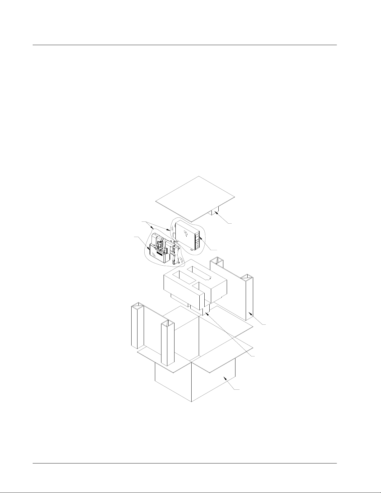
Unpacking and Re-Packing Instructions
Unpacking
1: Remove binding straps from the carton and discard.
2: Break tape seal and open carton.
3: Remove Top Foam and set aside.
4: Lift Sonic Knife and Sonic power supply directly up, out of the foam pocket.
5: Remove Poly Bags.
6: Set the Sonic Knife on its back cover (the same position as it sits in the carton).
7: Remove the tool bag, machine manual and power cord.
POLY BAG
SONIC KNIFE
TOP FOAM
SONIC POWER SUPPLY
SIDE FILLER SUPPORT
BOTTOM FOAM
CARTON
Repacking
Follow procedure in reverse order. It is not required to band the package if straps are
not available.
Users Manual Sonic Knife w/500 Operation •••• 8
Page 9

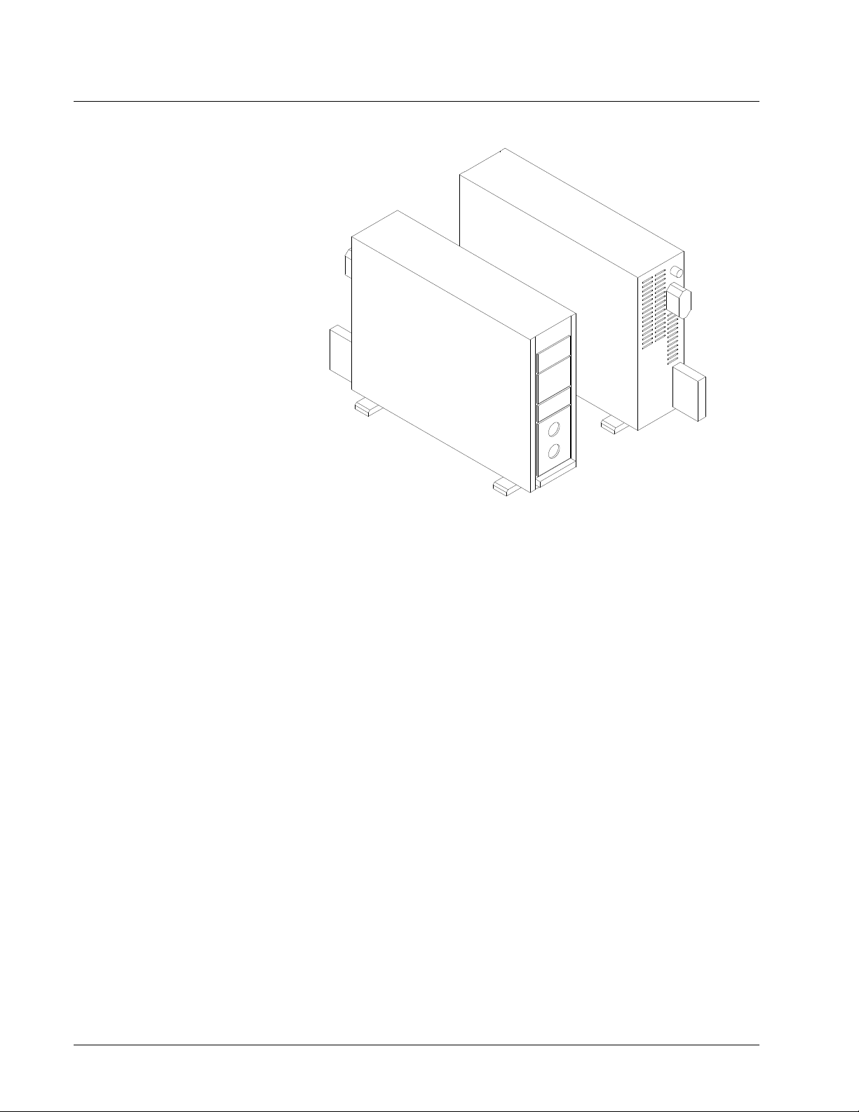
Location of Sonic Knife
The Sonic Knife weighs approximately 25 Lbs. (12Kg). A table of sufficient quality
and strength should be used to support the sonic knife once it is mounted to a suitable
printer.
The Sonic Knife should be located in an area that the ultrasonic noise emitted from
the cutting operation will not affect others. AVERY DENNISON has taken many
steps to keep the Sonic Knife noise to the lowest level. The Sonic Knife is not
recommended for an office environment.
The power source of the Sonic Knife should be a dedicated line. The first sign that
the Sonic Knife is not being supplied with sufficient power is the ultrasonics will stop
cutting, but the rest of the Sonic Knife will appear fully functional.
Unit Specification
Label Size Max: - 2.00" (51mm) web x up to 8" (203 mm) feed
Min: - 5/8" (16mm) web x 1.2" (30.5mm) feed – Also listed in Appendix B
Print Speed Minimum Length
3 IPS 1.2” (30.5 mm)
4 IPS 1.6” (40.7mm)
4.5 IPS 1.8” (45.8mm)
5 IPS 2” (50.8mm)
6 IPS 2.4” (61mm)
7 IPS 2.8” (71.2mm)
Justification Material must be centered over ultrasonic horn.
Sense Mark The sense mark is not required – does not register to a sense mark – The printer controls the cut position
Speed Controlled by speed of printer – See chart in Appendix B.
Stock Polyester woven edge fabric and AVERY DENNISON So-Soft® Products
Interface Cabling to printers and to Sonics
Dimensions 16.0" (406mm) high x 5 1/2" (138mm) wide x 14" (356mm) deep
Weight
Electrical 90-132 / 180-265 VAC 50-60Hz 10/5Amp - factory set
Temperature
Humidity 5% to 90% non-condensing
Options - Flag cutting – (Controlled by printer)
25 Lbs. (12Kg).
41°F (5°C) to 104°F (40°C)
- Spare Parts Kit not required
- International Hardware Kit
The Sonic Knife is a modular design, which can be added to the AVERY
DENNISON fabric printers - including the 500, 545, 636, 656 and 676 thermal
transfer printers.
Users Manual Sonic Knife w/500 Operation •••• 9
Page 10
Ultra Sonic Power Supply
Caution
Only qualified technicians should service the power supply.
The ultrasonic attachment is made up of several components. They are the power
supply, the horn assembly and the connecting cable. In addition there is a knife
assembly with a changeable tool steel blade.
The power supply should be located next to the Sonic Knife. This unit generates
electrical pulses at 35 KHz to the converter. The power supply must be turned on
and off separately from the main printer. The power supply contains no ON/OFF
switch. Power on/off is accomplished by either plugging/unplugging the power
supply. The front display has several setting adjustments and status indicators.
Line Cord
Connects the power supply to line power.
Fuse
Refer to the nameplate on the ultrasonic power supply for replacement fuse
information.
RF Cable to Sonic Converter
Interface cable from the power supply to the converter.
Users Manual Sonic Knife w/500 Operation •••• 10
Page 11

Custom Trigger
The interface cable from the Sonic Knife is used to turn the Sonics off and on. The
sonic unit is on all the time the stacker is running.
Air Cooling
The Sonic Horn does not require special cooling. However, to maintain optimum
efficiency, keep the horn stack area and the back cover cooling vents free from
debris and clutter.
Connecting The Power Supply
Connections
Connect the 37-pin Connector and the Coaxial Converter Cable from Sonic Knife as
shown in the illustration below. Secure AC outlet cord to suitable outlet. NOTE:
There is no AC power switch on the Power Supply. It will be on whenever the power
cable is plugged in.
COAXIAL CONVERTER
CABLE
37 PIN CONNECTOR
AC POWER CABLE
Users Manual Sonic Knife w/500 Operation •••• 11
Page 12
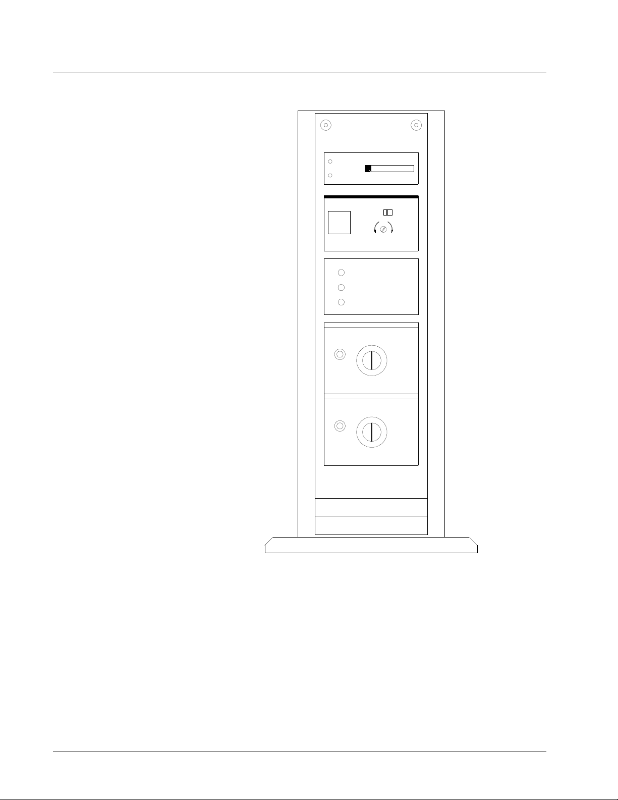
Operating The Power Supply
TELESONIC
ULTRASONICS
TEST
LOAD
TEST
CUTTING-CONTROL
100
200
2
10
50
10
AUTO MAIN
TUNING
OVERLOAD
OVERTEMP
POWER
1
0
1
2
3
10
4
9
5
8
6
7
MS
US-TIME
100
0
1
2
3
10
4
9
5
8
6
7
MS
20
100
SG3510 CT
The Ultrasonic Power Supply is pre-programmed for the correct settings at the
factory. The following instructions describe how to check and change these settings.
IMPORTANT: FOR PROPER OPERATION, USE THE FACTORY SETTINGS
AT ALL TIMES. CHANGING THESE SETTINGS MAY RENDER THE
SONIC KNIFE INOPERABLE, REDUCE THE QUALITY OF THE CUT
AND/OR REDUCE THE RELIABILITY OF THE SONIC KNIFE.
Users Manual Sonic Knife w/500 Operation •••• 12
Page 13

Settings
The Power Supply is set properly at the factory. Any changes to the factory setting
may result in improper operation. If necessary, the factory settings may be restored as
follows:
AUTO/MAN switch AUTO
CUTTING CONTROL 0
US-TIME 0
Users Manual Sonic Knife w/500 Operation •••• 13
Page 14
Installation
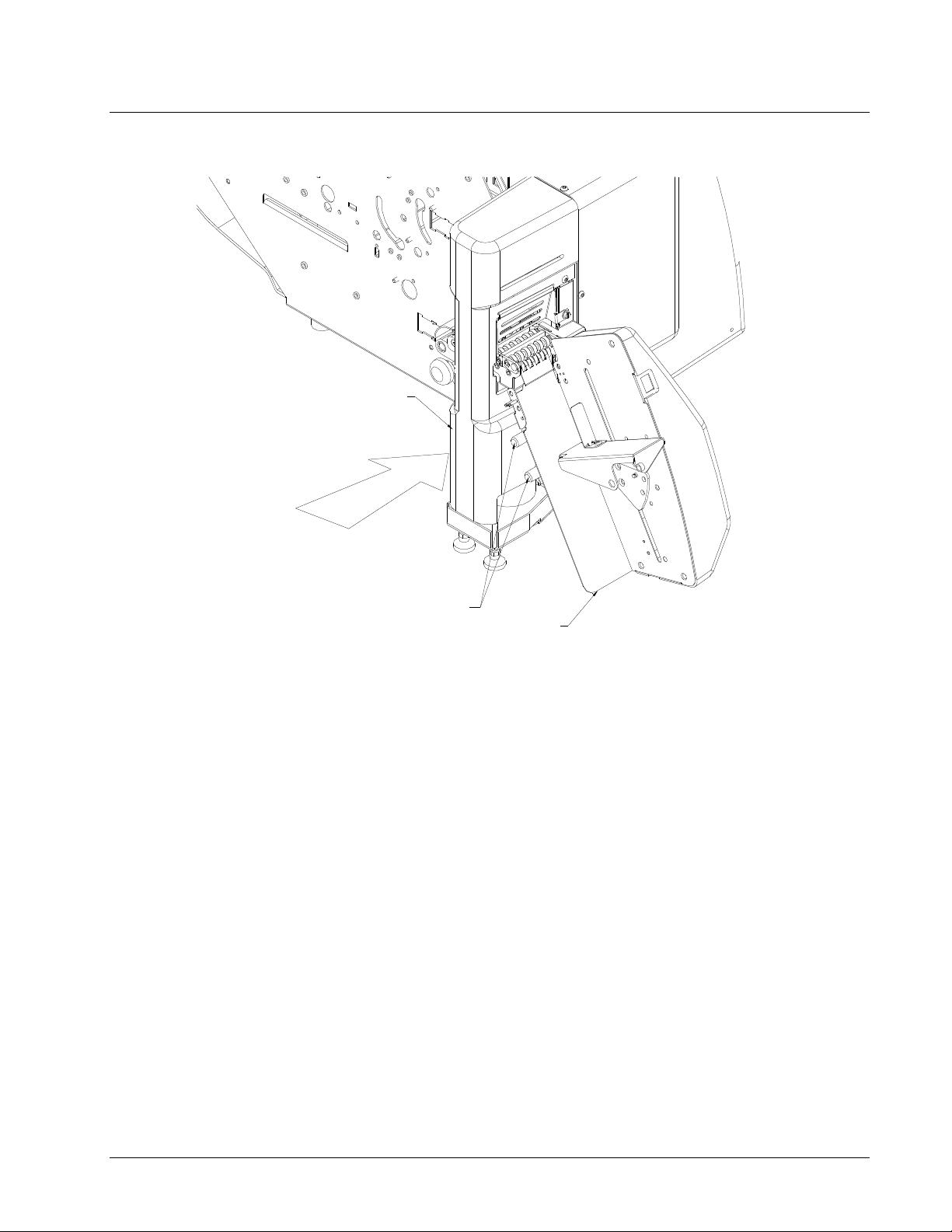
Attaching Sonic Knife – AVERY DENNISON 500
STACKER
SONIC KNIFE
PAXAR 500
PAXAR 500
POST BRACKET
FIGURE 1
There are two exit posts on the AVERY DENNISON 500. To attach Sonic Knife to
the AVERY DENNISON 500, slide the Sonic Knife onto the bottom post, using the
post bracket. Adjust the Sonic Knife forward/backward so the web coming from the
printer is centered on the horn face. Connect cables per electrical schematic.
Users Manual Sonic Knife w/500 Installation •••• 14
Page 15
Attaching Sonic Knife – Stacker
SONIC KNIFE
POST
STACKER
FIGURE 2
There are two posts on the outfeed end of the Sonic Knife. Slide the stacker onto the
posts. Adjust the stacker backward/forward and will pivot so the cut labels stack
uniformly. Connect cable per electrical schematic.
Users Manual Sonic Knife w/500 Installation •••• 15
Page 16

Cable Connections to 500 Printer
STACKER
STACKER CABLE
SONIC KNIFE
PAXAR 500
CONNECTOR LOCATION
FIGURE 3
SONIC KNIFE
PAXAR 500
STACKER
PRINTER CABLE
CONNECTOR LOCATION
FIGURE 4
Users Manual Sonic Knife w/500 Installation •••• 16
Page 17

Connecting the Sonic Knife to the Printer and Ultrasonic
Power Supply
1. The Sonic Knife requires a cable that is installed in the printer. Since this
cable is different for each printer, refer to the installation instructions that
come with the cable. Factory selected options have the internal cable
already installed.
2. Locate the Ultrasonic Power Supply in a convenient location near the Sonic
Knife.
3. Connect the Coaxial Converter Cable from the Ultrasonic stack to the
Ultrasonic Power supply by pressing the connector firmly into the socket.
4. Connect the 37-pin D-shell connector to the 37-pin connector on the rear of
the power supply. Tighten the mounting screws to secure the connector.
5. Connect the large D-shell connector to the connector installed in the printer
(step 1). Tighten the mounting screws to secure the connector.
6. Connect the power cord to the Ultrasonic Power Supply and the AC power
source.
NOTE: There is no AC (mains) power switch on the Power Supply. It
will be on as long as it is plugged in. Ultrasonic energy is generated only
while cutting.
Ultra Sonic Horn "Stack"
Cutter Set-up
The "Converter / Horn" assembly is called the "Stack".
The converter receives the electrical pulses from the power supply and converts them
to mechanical lineal motion. This causes the horn to vibrate at 40 KHz acting like a
tiny impact hammer. This action causes friction heat that cuts and fuses the label
tape.
CAUTION: The horn can cause burns if touched during operation
The Sonic Knife has been set-up at the factory to run a checkout stock as the
minimum checkout requirement. Depending on the shipping destination and the
information supplied to the factory, the actual production job the customer has
ordered will be tested.
At times the unit will require adjustment and maintenance. The top knife will need to
be replaced and leveled, the stack will also need to be adjusted to cut in a new
location, and general tuning will need to be done to keep the Sonic Knife in top
running condition. The following sections are in order of procedure to set-up the
knife and to keep the Sonic Knife cutting properly.
Users Manual Sonic Knife w/500 Installation •••• 17
Page 18

Loading the Machine
FEED ROLLER KNOB
WEB GUIDE KNOB
WEB GUIDE
WEB
SNUBBER BRAKE
FIGURE 5
To load the Sonic Knife, start by making sure the snubber brake is in the “up”
position. If it's not in the up position – press start and stop, to cycle the system for
one label. Feed fabric under the snubber brake until it stops at the upper and lower
feed rollers. Using the feed roller knob, advance the fabric through the machine until
it makes it way past the knife blade and out to stacker.
The upper feed roller is automatically spring loaded, so there is no feed pressure
adjustment necessary.
Users Manual Sonic Knife w/500 Installation •••• 18
Page 19

Machine Maintenance
Replacing the Knife Blade
KNIFE GUARD
KNIFE SCREW
LEVELING PIN
FIGURE 6
Because the knife blade will eventually wear from abrasion caused by ultrasonic
vibration when the horn face and the knife blade are in contact, the knife blade will
need to be replaced periodically.
To replace the knife blade, remove the knife blade guard. The knife is attached to a
self-leveling mount with a leveling pin. Loosen and remove the (2) knife screws and
remove the blade from the leveling pin. Replace the new knife blade. Thread the (2)
knife screws into the knife mount but do not tighten. The blade must be leveled each
time it is replaced. See knife blade leveling procedure.
When removing the knife blade, the blade may seem tightly mounted to the knife
mount pin. Pull blade off of mount (leveling) pin by pulling from the top of the
blade.
Users Manual Sonic Knife w/500 Machine Maintenance •••• 19
Page 20

Leveling the Knife Blade
CAM ADVANCE SCREW
9/64TH WRENCH
OUTFEED GUARD
KNIFE SCREW
KNIFE BLADE ASS'Y
HORN
FIGURE 7
1: Remove the Outfeed Guard.
2: Loosen the (2) Knife Screws and using a 9/64th Wrench, advance the roller cam
until the Knife Blade assembly compresses against the Horn Surface. Make sure
the knife spring is fully compressed.
3: Tighten the (2) Knife Screws and using the 9/64th Wrench, advance the roller cam
back up to its original home position.
Note: Exit conveyor for SNAP not shown for clarity.
Users Manual Sonic Knife w/500 Machine Maintenance •••• 20
Page 21

Knife Pressure Adjust
9/16" ADJUST NUT
1/2" LOCKING NUT
ADJUSTING NUT ROD
SPRING NUT
.750
.015 GAP
KNIFE BLADE ASSEMBLY
SONIC HORN
FIGURE 8
Proper spring pressure and dwell are set at the factory. However, adjustment may be
necessary from time to time. The factory settings are as follows:
Sharp Blade spring height - .750” Dwell - .015”
Dwell is measured while the knife blade assembly is fully compressed against the
sonic horn.
Spring height is measured when the knife blade assembly is in the “up” position.
To adjust the knife blade pressure, use the supplied 9/16” wrench (part # 571399), to
turn the Adjusting Nut clockwise/counter clockwise to achieve desired pressure. The
nut bracket will keep the spring nut from rotating and allow easy turning of the adjust
nut.
To adjust knife blade dwell, use the supplied 9/16” wrench to hold Adjusting Nut in
place. Use ½” wrench to loosen the Locking Nut. Turn the Spring Nut to move the
Adjusting Rod up/down for desired gap setting.
Users Manual Sonic Knife w/500 Machine Maintenance •••• 21
Page 22

1/2" WRENCH
9/16" WRENCH
OUTFEED GUARD
FIGURE 9
Users Manual Sonic Knife w/500 Machine Maintenance •••• 22
Page 23

Proximity Switch Adjustment
The Proximity Switch triggers the Ultrasonic Power Supply to begin generating
Ultrasonic energy during the cut. If the Proximity switch is not adjusted properly, the
Power Supply will not be triggered and the unit will not cut.
The Proximity Sensor Flag (see illustrations below) should be adjusted as shown.
The flag should be positioned so that there is a 0.015” (0.4mm) gap between the Flag
and the face of the Switch. And, in the home position, the proximity flag should be
approximately 25 degrees below the proximity sensor.
PROXIMITY
SWITCH
PROXIMITY SWITCH
COLLAR FLAG
.015
Note: Above view is looking down on top of machine.
SONIC KNIFE FRONT
PROXIMITY SENSOR
PROXIMITY FLAG
25°
UPRIGHT PLATE
Users Manual Sonic Knife w/500 Machine Maintenance •••• 23
Page 24

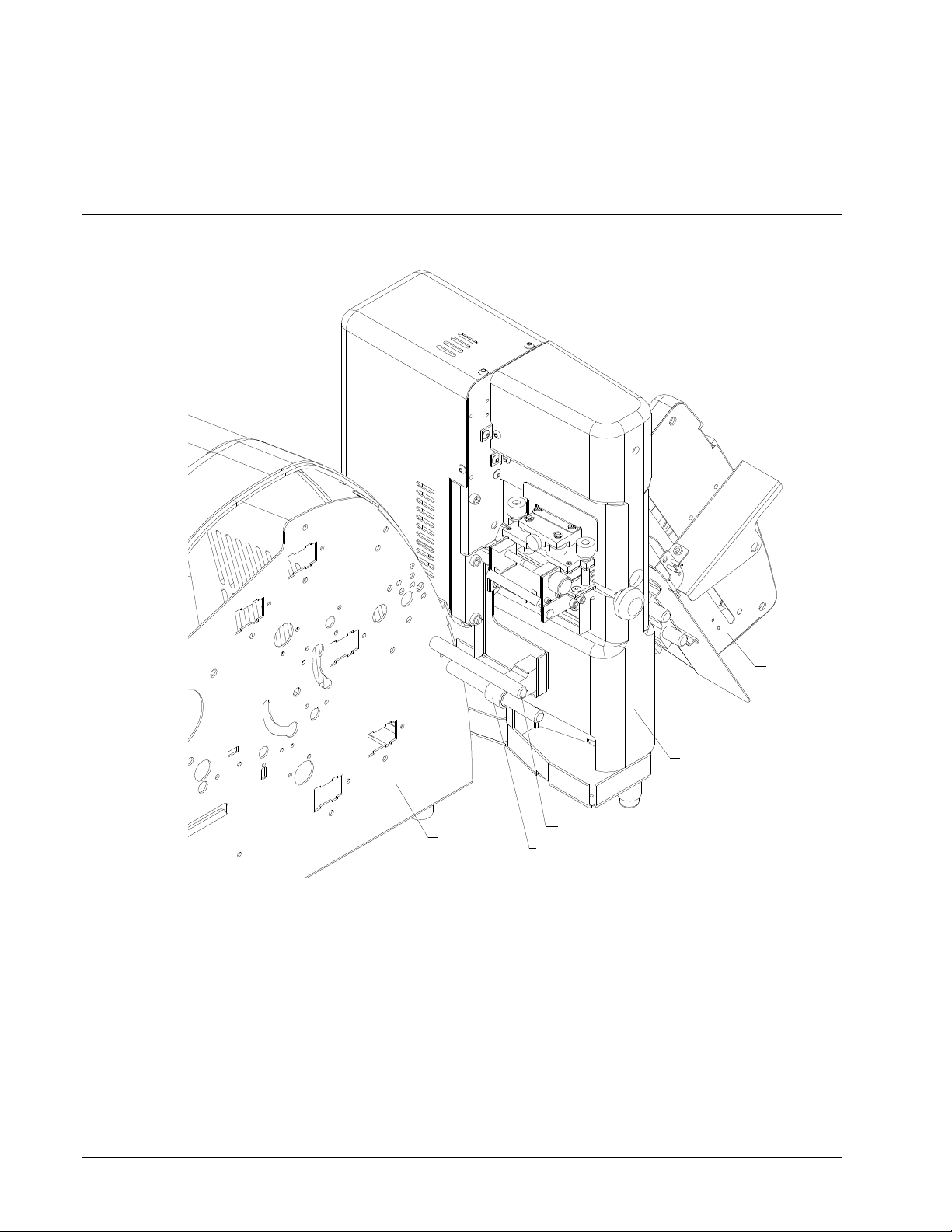
Horn Replacement / Adjustment
GEAR GUARD
KNIFE GUARD
FRONT COVER
HORN MOUNT
EXIT CONVEYOR
HORN MOUNT SCREW
HORN STACK
FIGURE 10
For horn replacement or adjustment remove the Sonic Knife cover, Knife Guard and
the exit conveyor. Remove the horn mount screws and horn clamp screws. Remove
the horn mount and horn clamp. The horn will slide out from its mount.
When replacing the horn, before tightening the horn clamp screws, make sure the
horn is parallel with the knife blade. Replace and tighten the horn mount screws.
Replace and tighten the horn clamp screws and follow the procedure for leveling the
knife blade.
Users Manual Sonic Knife w/500 Machine Maintenance •••• 24
Page 25

Exit Conveyor
KNIFE
GUARD
CONVEYOR
TOP
ROLLERS
EXIT
CONVEYOR
FIGURE 11
To clear any jam that may occur in the exit conveyor, first remove the Knife Guard.
Rotate the Conveyor Top Rollers on the exit conveyor to expose the web path.
Remove any jammed or loose material. Replace the Conveyor Top Rollers, making
sure they are down all the way. Replace the Knife Guard.
Users Manual Sonic Knife w/500 Machine Maintenance •••• 25
Page 26

Machine Maintenance
SIDE
LOCK
SCREW
TOP LOCK SCREW
FIGURE 12
To clean, flip back the infeed conveyor by loosening the three thumb screws, two top
lock screws and one side lock screw as shown in figure 12.
Users Manual Sonic Knife w/500 Machine Maintenance •••• 26
Page 27

Cleaning Infeed Rollers
CONVEYOR
TOP HALF
FIGURE 13
Clean the Upper Feed Roller and Lower Feed Roller using a Nylon toothbrush and
Alcohol. The rollers can be rotated using the feed roller knob. Be careful to prevent
any Alcohol from getting into the machine. Allow it to dry before starting the
machine. Note: Flipping back the infeed conveyor as described below can also be
used to clear any jams in the infeed conveyor area.
Users Manual Sonic Knife w/500 Machine Maintenance •••• 27
Page 28

Knife Spring Replacement
GEAR
GUARD
EXIT
CONVEYOR
KNIFE GUARD
KNIFE SCREW
KNIFE BLADE
POST SCREW & HOLDER
COVER
FIGURE 14
1) Remove knife guard, gear guard and exit conveyor. Remove the knife assembly
and the post screws and holders that secure the knife mount.
Users Manual Sonic Knife w/500 Machine Maintenance •••• 28
Page 29

SNUBBER
MOUNT
PLATE
TOP
CONVEYOR
FIGURE 15
2) Remove the front cover, the snubber and the feed assembly.
Users Manual Sonic Knife w/500 Machine Maintenance •••• 29
Page 30

SNUBBER
MOUNT
PLATE
SPRING POST
PLATE SCREW
KNIFE SPRING
"E" CLIP
KNIFE HOLDER
HOLDER INSULATOR
FIGURE 16
3) To replace the knife spring remove the “E” clip. Loosen the (2) plate screws,
drop the snubber mount and slide the knife spring off of the spring post. Replace
with the new knife spring.
Users Manual Sonic Knife w/500 Machine Maintenance •••• 30
Page 31

Troubleshooting
Problem Probable Cause Remedy
Machine fails to power up Lack of power to machine Check that both ends of power cord on printer are
securely plugged in.
Confirm that the outlet the printer is plugged into
has power.
Confirm all Sonic Knife cables are securely plugged
in.
Stock does not advance
through Sonic Knife when
printer start button is
pressed
Check to see Feed Rollers are clean.
Cut on one side of fabric only Out of level Knife Blade Follow Knife Blade leveling procedure on page 20
Fabric not centered on horn Check all label guides and mounting brackets to
Not cut on fabric Out of level Knife Blade Follow Knife Blade leveling procedure on page 20
Ground Detect “on” too soon Check to make sure home sensor triggers at TDC.
Sonic power supply off Make sure Sonic power supply is turned “on”.
Spring pressure too light Check Spring Pressure setting procedure on page 21
Spring pressure too heavy Check Spring Pressure setting procedure on page 21
Knife dwell setting incorrect Check Knife Dwell setting procedure on page 21
Jam in Feed Rollers Check Feed Rollers for obstruction or jam. If
necessary - Re-thread fabric through feed rollers.
make sure fabric is centered on horn.
Sonic Power Supply not triggering
(the bar indicator on the top front
of the Power Supply should flash
for every cut. If it does not, the
Power Supply is not being
triggered)
Users Manual Sonic Knife w/500 Machine Maintenance •••• 31
Check the Proximity Switch adjustment on page 23
Page 32

Appendix A
Manufactures of Hearing Protectors
AMERICAN OPTICAL COMPANY
Department 4041
Safety Division, 14 Mechanic Street
Southbridge, MA 01550
BILSON INTERNATIONAL, INC.
109 Carpenter Drive
Sterling, VA 22170
E-A-R
A Division of the CABOT CORPORATION
7911 Zionsville Road
Indianapolis, IN 46268
FLENTS PRODUCTS COMPANY, INC.
Ely Industrial Part, Building #2
Norwalk, CT 06854
GLENDALE PROTECTIVE TECHNOLOGY, INC.
130 Crossways Park Drive
Woodbury, L.I., NY 11797
SELLSTROM MANUFACTURING COMPANY
Sellstrom Industrial Park
220 South Hicks Road, Box 355
Palatine, IL 60067
Users Manual Sonic Knife w/500 Appendix A •••• 32
Page 33

Appendix B
Label / Machine Speed
The maximum label length for the Sonic Knife is the same as the printer to which it is
attached. The minimum label length depends on the print speed. The following chart
indicates the minimum label length for various print speeds.
Print Speed Minimum Length
3 IPS 1” (25 mm)
4 IPS 1.6” (40 mm)
4.5 IPS 1.7” (42mm)
5 IPS 2” (52mm)
6 IPS 2.3” (58mm)
7 IPS 2.8” (70mm)
Users Manual Sonic Knife w/500 Appendix B •••• 33
Page 34

Installation Instructions for
Stacker Option 580028
(Use with Woven Edge Fabrics less than 1 inch wide & over 4 inches long)
Option consists of:
Part No. Description Qty
588048 Web Guide 1
588049 Long Stacker Mount Shaft 2
Installation Procedure
1. Remove (2) Stacker Mounting Shafts from the Sonic Knife and replace with
(2) 588049 long Stacker Mount Shafts.
REMOVE STACKER MOUNTING
SHAFTS & REPLACE WITH LONG
STACKER MOUNTING SHAFTS
(588049)
2. Adjust to allow Stacker to slide freely.
3. With Stacker installed, slide forward and tilt top back as far as possible
without blocking the Platform “Drop” Sensor.
Users Manual Sonic Knife w/500 Installation Instructions for Stacker Option 580028 •••• 34
Page 35

4. Install Magnet backed Web Guide in position as shown below.
WEB GUIDE WITH
MAGNET
5. Slide Stacker horizontally until Label exiting Nip Roller slides across edge
of Web Guide as shown.
EDGE OF LABEL SHOULD
GLIDE ACROSS BENT EDGE
OF WEB GUIDE
Note: The single Web Guide creates a twist in the Label that gives it enough rigidity to be pushed
into the Stacker.
Users Manual Sonic Knife w/500 Installation Instructions for Stacker Option 580028 •••• 35
Page 36

Electrical Schematic
Users Manual Sonic Knife w/500 Electrical Schematic •••• 36
Page 37

115V / 230V Schematic
SONIC KN IFE WIT H FIB FO R 500
11 5V / 23 0V
TO SNAP PRINTER 13W3 OUT PUT
FOR SONI C KNIFE (REQUIRE S 581143 )
HOST PRINTER MCB J35,23 (SK TAMP H)
HOST PRINTER MCB J35,19 (CUT PULSE H)
HOST PRINTER MCB J35,21 (CUT PULSE L)
HOST PRINTER MCB J35,9 (SK ERROR)
HOST PRINTER MCB J35,1 (EE PROM DATA)
HOST PRINTER MCB J35,2 (EE PROM GND)
HOST PRINTER 5V HARNESS RED (5V)
HOST PRINTER 24V HARNESS GRAY (24V)
HOST PRINTER 24V HARNESS BLACK (GND)
J3CON10
A
A
A
J24
CON3
1
2
3
4
5
6
7
8
9
10
1
2
3
571119
1
2
CON2
ULTRA SO NIC POW ER SUPPL Y
115V TEL SONIC S G-3510-C T 571151
230V TEL SONIC S G-3510-C T 571155
POWER
JX39
1 (SHIELD GND)
2 (0V)
3 (+24V)
4 (+24VGS)
7 (US-0N+)
8 (US- ON-)
9 (SONO+)
10 (SONO-)
11 (TIM+)
12 (TIM-)
17 (US+)
18 (US-)
OUTPUT
TO WALL OUTLET
PROXIMIT Y SENSO R COMPON ENT OF CA BLE SET 571153
BROWN
BLUE
BLACK
LINE COR D
115V 5-1 5P 1811 34
230V 6-1 5P 5711 34
1
2
3
J?
ULTRA SON IC STACK 571157
ULTRA SO NIC CON VERTER
LS?
OUTPUT C ABLE CO MPONENT O F CABLE SET 571 153
ULTRA SONIC HORN
571114
J?
J?
1/2 3/4
1
2
J29
J30
CON2
3
8
1
17
2
9
10
1/2HOST PRINTER MCB J35,25 (SK TAMP L)
J1 SYSTEM HARNESS
FIB PCB 341107S K
J2 IN FROM HOST (16 pin)
J4 IN FROM HOST (7 pin)
J8 STEPPER MOTORJ7 5VDCJ6 24VDC
J10 DC MOTOR
J9 SOLENOIDS
J11 SOLENOID
J3 OUT TO OPTION (16 pin)
J5 OUT TO OPTION (7 pin)
351132
1-7
2
3
9
CON3
HARNESSED KNIFE SENSOR
1
1
2
2
3
3
CON3
1
2
MG3
3
456
KNIFE MOTOR
371111
371131
ISO?
+
M?
ROLLER MOTOR
A
1
2
CON2
J25
J26
1
2
CON2
351161
-
Users Manual Sonic Knife w/500 •••• 37
Page 38

500 Downstacker Schematic
500 DOWN STACKER
115V / 230V 580005
TO SNAP 20 PIN
STACKER OUTPUT
581142
NEEDED UNTIL 581155 REV 3 RECEIVED.
CON20
J16
1
2
3
4
5
6
7
8
9
10
11
12
13
14
15
16
17
18
19
20
1
2
3
4
5
6
7
8
9
10
11
12
13
14
15
16
17
18
19
20
EE PROM
CON20CON20
1
2
3
4
5
6
7
8
9
10
11
12
13
14
15
16
17
18
19
20
J11J28
581155
J19
1
2
3
CON3
J?
1
2
3
CON3
J12
1
2
3
4
5
6
7
8
CON8
581137
SW1
996159
J13
CON8
1
2
3
CON3
J15
1
2
3
4
5
6
7
8
J?
CON3
1
2
3
4
J?
J14
1
2
3
CON3
J18
1
2
3
CON3
1
2
3
1
2
3
CON3
J?
1
2
3
CON3
LOWER STACK POSITION SENSOR
MG2
6
6
5
TRAY MOTOR
588039
UPPER STACK POSITION SENSOR
371133
ISO?
371133
ISO?
STACKER FULL SENSOR
371130
ISO?
Users Manual Sonic Knife w/500 •••• 38
Page 39

Assembly Drawings Mechanical
Users Manual Sonic Knife w/500 Assembly Drawings Mechanical •••• 39
Page 40

Cover Assembly
1
5
7
2
5
6
5
10
Users Manual Sonic Knife w/500 Assembly Drawings Mechanical •••• 40
8
7
3
4
9
Page 41

Cover Parts List
Item Part # Description Qty
1 571204 COVER, BACK 1
2 571209 BRACKET, FRONT COVER 3
3 571206 COVER, OUTFEED GUARD 1
4 571208 COVER, BLADE GUARD 1
5 990090 10-32 X 3/8" BUTTON HD CAP SCREW 13
6 990122 1/4-20 X 3/4" SOCKET HD CAP SCREW 3
7 990469 #10 FLAT NYLON WASHER 2
8 991490 SCREW, THUMB 10-32 X 3/8" 1
9 570015 SONIC KNIFE, DRIVE ASSEMBLY 1
10 571225 COVER, FRONT 1
Users Manual Sonic Knife w/500 Assembly Drawings Mechanical •••• 41
Page 42

Drive Assembly
22
25
3
14
7
17
16
20
10
15
30
29
2
18
25
24
18
13
20
27
14
5
15
2
19
26
8
21
9
23
1
20
12
23
6
11
14
4
20
28
Users Manual Sonic Knife w/500 Assembly Drawings Mechanical •••• 42
Page 43

Drive Parts List
Item Part # Description Qty
1 996154 ELECTRICAL, CLAMP .35 DIA 1 17 989994 2-56 X 1/2" SOCKET HD CAP SCREW 1
2 571008 FRAME, UPRIGHT 1 18 371111 MOTOR, STEP 1
3 571005 FRAME, STEP MOTOR 1 19 991485 GEAR, 72T 1/4" BORE 1
4 351161 DC FEED MOTOR 1 20 990051 8-32 x 3/8 SOCKET HD CAPSCREW 11
5 571007 FRAME, FEED MOTOR 1 21 990020 6-32 BUTTON HD CAP SCREW 4
6 572041 SHAFT, FEED EXT. 1 22 577061 COLLAR, FLAG 1
7 358024 JAM SENSOR BRACKET 1 23 996153 ELECTRICAL, CLAMP .19 DIA 1
8 571006 FRAME, PC BOARD 1 24 572053 DRIVE, 96T GEAR 1
9 341107 FIB BOARD 1 25 991503 48T SPROCKET 1
10 571009 FRAME, SENSOR BRACKET 1 26 570015 SONIC KNIFE, CUT ASSEMBLY 1
11 571012 SPACER, FRAME 1 27 570015 SONIC KNIFE, CUT ASSEMBLY 1
12 105023 KNOB, IMPRESSION ADJUST 1 28 571157 SONIC HORN STACK, 1000W 1
13 999172 1/4-20 X 1 1/4" FLAT HD CAP SCREW 4 29 571154 PROX SWITCH 1
14 990080 10-32 X 3/8" SOCKET HD CAP SCREW 10 30 572055 PROX SWITCH COLLAR 1
15 990058 8-32 X 1/4" SOCKET SET SCREW 4 31 571150 CONVERTER, 1000W (NOT SHOWN) 1
16 990015 6-32 X 1/4" SOCKET HD CAP SCREW 2 32 571153 SONIC CABLES (NOT SHOWN) 1
Item Part # Description Qty
Users Manual Sonic Knife w/500 Assembly Drawings Mechanical •••• 43
Page 44

Cut Assembly
2
3
1
4
Users Manual Sonic Knife w/500 Assembly Drawings Mechanical •••• 44
5
Page 45

Cut Assembly Parts List
Item Part # Description Qty
1 570015 SONIC KNIFE, INFEED CONVEYOR 1
2 570015 SONIC KNIFE, H FRAME ASSEMBLY 1
3 575004 TELSONICS SONIC STACK, (SHOWN FOR REF.) 1
4 577077 BRACKET, HORN MOUNT 1
5 990121 1/4-20 X 5/8 SOCK HD CAP SCR 2
Users Manual Sonic Knife w/500 Assembly Drawings Mechanical •••• 45
Page 46

Infeed Conveyor Assembly
38
24
37
27
13
32
2
28
20
6
16
19
21
42
4
8
18
23
4
7
17
40
41
12
25
35
9
2
29
3
22
10
26
25
36
11
18
14
5
15
24
Users Manual Sonic Knife w/500 Assembly Drawings Mechanical •••• 46
1
31
38
Page 47

Infeed Conveyor Assembly Parts List
Item Part # Description Qty
1 574097 ROLLER, BOTTOM 1
2 999014 BUSHING, 1/4 X 3/8 X 3/4" 4
3 574096 ROLLER, TOP 1
4 574095 SHAFT, SNUBBER 2
5 999157 BUSHING, 3/8 X 5/8 X 1" 2
6 990325 SNAP RING, 3/16 E-RING 2
7 991451 COMPRESSION SPRING, .156 OD X .132 ID 2
8 991493 SPRING, COMPRESSION (SNUBBER) 2
9 574081 WEB GUIDE, RH 1
10 574080 WEB GUIDE, LH 1
11 196028 KNOB, BLACK (GLOSS) 1
12 574089 LOWER BRIDGE PLATE 1
13 574086 BASE CONVEYOR BRACKET 1
14 574098 SNUBBER PAD 1
15 574090 SNUBBER BRACKET 1
16 574085 SNUBBER LOCK PLATE 1
17 574083 SNUBBER TIE PLATE 1
18 990118 1/4-20 X 3/8 CAP SCREW 4
19 990313 THUMB SCREW KNOB, #10 1
20 990072 8-32 X 1/" FLAT HD CAP SCREW 2
21 990087 HEXAGON SOCKET HEAD CAP SCREW 1
22 574084 WEB GUIDE BASE 1
23 574094 SPRING INSERT 2
24 990401 RIVIT, 3/18 C 3/8" FLAT HEAD 2
25 990261 3/16" SNAP RING 2
26 991481 BEARING, 3/16 X 5/16" FLANGE BUSHING 2
27 991484 GEAR, 36T 1/4" BORE 1
28 571223 COVER, GEAR 1
29 574082 SHAFT, ADJUSTING 1
30 990028 6-32 X 3/8" FLAT HD CAP SCREW 2
31 574087 BASE CONVEYOR, LH 1
32 574088 BASE CONVEYOR, RH 1
33 574091 TOP CONVEYOR, LH 1
34 574092 TOP CONVEYOR, RH 1
35 574093 UPPER BRIDGE PLATE 1
36 990015 6-32 X 1/4 SOCKET HD CAP SCR 4
37 990051 8-32 X 3/8 SOCKET HD CAP SCR 2
38 990082 10-32 X 5/8 SOCKET HD CAP SCR 4
39 990006 4-40 X 1/4 SOCKET HD CAP SCR 4
40 991210 KNOB, ADJUST 2
41 574099 SHAFT, ADJUSTMENT KNOB 2
42 571224 COVER, SNUBBER 1
Users Manual Sonic Knife w/500 Assembly Drawings Mechanical •••• 47
Page 48

H Frame Assembly
11
10
15
23
4
14
28
27
2
5
9
13
12
6
13
1
3
29
30
21
19
16
17
18
20
33
31
21
19
26
25
24
32
33
35
34
Users Manual Sonic Knife w/500 Assembly Drawings Mechanical •••• 48
Page 49

H Frame Assembly Parts List
Item Part # Description Qty
1 427026 NUT, ADJUSTMENT 1 19 427061 BUSHING INSULATOR 4
2 999142 BUSHING, 1/2 X 3/4 X 2" 2 20 427062 INSULATOR, KNIFE HOLDER 2
3 427035 SPRING, COMPRESSION (NOT SHOWN) 1 21 990091 10-32 X 1/2 BUTTON HD CAP SCREW 4
4 577035 SHAFT, EXTENSION 1 22 990256 1/4" STEEL PIN 1
5 991427 BUSHING, 1/2 X 13/16 X 1/2" 1 23 990058 8-32 x 1/4" SET SCREW 2
6 991428 NUT, JAM 5/16-24 1 24 577060 BRACKET, NUT 1
7 572040 SHAFT, SPRING MOUNT 1 25 990029 6-32 X 1/4" FLAT HD CAP SCR 1
8 577036 SHAFT, SMALL EXTENSION 1 26 990050 8-32 X 1/4" SOCKET HD CAP SCREW 1
9 999146 BUSHING, 3/8 X 1/2 X 1/2" 2 27 572049 TIE PLATE 1
10 577029 BRACKET, LIFTER 1 28 990144 # 10 FLAT WASHER 2
11 577034 SHAFT, EXTENSION 1 29 990326 SNAP RING, 1/4 E-RING 1
12 577032 SHAFT, ADJUST 1 30 577078 H FRAME 1
13 577019 SHAFT, POST 2 31 577056 KNIFE BLADE 1
14 990081 HEXAGON SOCKET HEAD CAP SCREW 2 32 990121 1\4-20 X 5/8" SOCKET HD CAP SCREW 2
15 990080 10-32 X 3/8" SOCKET HD CAP SCREW 2 33 990119 1/4-20 X 3/8 CAP SCREW 6
16 577053 BRACKET, SNUBBER MOUNT 1 34 999008 BEARING, R12FF 1
17 577054 BRACKET, INSULATOR PLATE 1 35 577077 BRACKET, HORN MOUNT 1
18 577055 BRACKET, KNIFE MOUNT 1 36 577077 BRACKET, HORN MOUNT 1
Item Part # Description Qty
Users Manual Sonic Knife w/500 Assembly Drawings Mechanical •••• 49
Page 50

Sonic Knife for AVERY DENNISON 500 Assembly
1
9
15
10
16
16
6
7
24
SEE NOTE 1
25
POWER SUPPLY AND
CABLING NOT SHOWN
5
28
27
26
19
10
17
18
21
20
8
14
13
22
12
23
11
STACKER ASSEMBLY
SHOWN FOR REF. ONLY
Users Manual Sonic Knife w/500 Assembly Drawings Mechanical •••• 50
Page 51

Sonic Knife for AVERY DENNISON 500 Parts List
ITEM NAME DESCRCRIPTION QTY
1 570002 ASSEMBLY, SONIC KNIFE 1
2 571215 COVER, GEAR 1
3 571207 COVER, INFEED GUARD 1
4 571208 COVER, BLADE GUARD 1
5 571014 FRAME, FOOT PLATFORM 1
6 571015 FRAME, LOCATOR GUARD 1
7 571016 FRAME, LOCATOR BLOCK 1
8 990469 #10 FLAT NYLON WASHER 2
9 990428 #10-32 X 1/4" NYLON SCREW 1
10 572046 ASS'Y, CONVEYOR 1
11 580005 STACKER ASSEMBLY (SHOWN FOR REF. ONLY) 1
12 578049 BRACKET, MOUNT 1
13 578048 BRACKET, ARM 1
14 990154 1/4-20 X 1/2" BUTTON HD CAP SCREW 4
15 990090 10-32 X 3/8" BUTTON HD CAP SCREW 8
16 990122 1/4-20 x 3/4" SOCKET HD CAP SCREW 4
17 990080 10-32 x 3/8" SOCKET HD CAP SCREW 2
18 990120 1/4-20 X 1/2" SOCKET HD CAP SCREW 3
19 588023 SHAFT, STACKER MOUNT 2
20 991199 BUMPER, RUBBER 8-32 2
21 571220 BRACKET, FOOT EXT. 2
22 990052 HEXAGON SOCKET HEAD CAP SCREW 2
23 990146 HEX MACHINE SCREW NUT UNC 2
24 999779 1/2 X 5/8 X 1 1/2" BUSHING 1
25 571198 ULTRA SONIC POWER SUPPLY KIT 115V 1
26 571020 FOOT, OUTRIGGER 1
27 571021 FOOT, SPACER 1
28 991536 5/165 X 1/4" SHOULDER SCREW 1
Users Manual Sonic Knife w/500 Assembly Drawings Mechanical •••• 51
Page 52

Exit Conveyor Assembly
13
8
19
22
7
6
1
4
5
21
8
20
23
17
18
2
5
18
2
24
6
16
6
15
8
3
11
9
14
Users Manual Sonic Knife w/500 Assembly Drawings Mechanical •••• 52
8
3
10
22
20
Page 53

Exit Conveyor Parts List
Item Part # Description Qty Item Part # Description Qty
1 578040 Shaft, Bottom roller 1
2 572054 Drive, 30T Gear 2
3 578041 Shaft, Drive roller 1
4 578039 Shaft, Top roller 2
5 990401 Rivit, 3/18 x 3/8" Flat head 2
6 990261 3/16" Snap ring 4
7 578044 Bracket, Roller mount 2
8 991481 Bearing, 3/6 x 5/16 Flange bushing 8
9 578046 Bracket, Base 1
10 578043 Bracket, Lower stripper 1
11 578047 Bracket, Base mount 1
12 578042 Bracket, Upper stripper 1
13 578045 Bracket, Mount standoff 1
14 990065 8-32 x 3/8" Button hd cap screw 2
15 990088 10-32 x 3/8" Flat hd cap screw 2
16 572044 Gear, 30T Idler 1
17 572045 Gear, 36T Rework 1
18 990025 6-32 x 1/4" Set screw 3
19 990051 8-32 x 3/8" Socket hd cap screw 2
20 584034 Electrical, Static brush 2
21 578050 Bracket, Static brush 1
22 990006 4-40 x 1/4" Socket hd cap screw 3
23 991471 4-40 x 1/4 Thumb screw 1
24 990446 3/16 x 1/2" Shoulder screw 1
Users Manual Sonic Knife w/500 Assembly Drawings Mechanical •••• 53
 Loading...