

Page 1

HowToRFID
How to RFID
With printers from Avery Dennison
Revision: 13 Date: 31 August 2009
Page 1 of 53
Page 2

HowToRFID
Revision history
Revision Date Author Changes
N/A Before 2007 M. Leiblich Changes have not been tracked in the past
7 2007-12-19 R. Boettcher Layout and document structure reworked
Section RFID basics removed
Section EasyPlug command description limited to commands not already
described in the EasyPlug manual (part of the printer documentation)
8 2008-05-30 R. Boettcher
9 2008-06-26 R. Boettcher Various changes indicating differences between standard printer firmware with
10 2008-08-21 R. Boettcher Adaptation of examples witch use PadLeft or PadRight functions to the syntax
11 2008-09-01 R. Boettcher
Section 3.1.2.1: Power level data updated (EU and US module data included)
Section 3.3.2.2: AWID Module identification clarified
Section 3.3.2.1: AWID Firmware compatibility list updated (EU Module => 4.10B)
Section: 4.1.1: HF Technology EAS bit added
Section 5.3.5.3: #RFC command description for modifying the EAS bit added
Section 6.2.7: Sample job for EPC/EAN128 4x6” shipping label added
Section 6.3 added an example for modifying the EAS bit of HF tags
RFID features and semi custom RFID firmware
New section 1 Summary of supported RFID features
New section 2.4.8 Processing failures (errors) – Bad tag signaling
Section 2.2: size limit of 224 bits user memory for NXP chip based tags removed
Section 3.3.2.1: size limit of 224 bits user memory for NXP chip based tags
removed
Section 3.1.2.1 Power level: power level tables and diagrams for AWID EU and
US RFID reader modules updated
Section 3.1.3 Parameters for error handling: description for parameter “Try
times” added
New section 3.1.5 Recommendations for web / material handling
New section 5.1.3 Operation / EasyPlug command matrix
Section 5: description of #SI command updated
Section 5: description of #RFL command added
Section 6: sample for usage of access password (EPC Gen 2 tags) updated
documented in the EasyPlug manual and implemented in firmware versions >=
x.33 (first standard release with RFID). The syntax was changed compared with
previous semi custom releases!
Affected examples:
Section 6.2.3: Write / Read / Print EPC with consecutive numbering
Section 6.2.6: Writing a SSCC-96 to tag
Section 6.2.7: EPC/EAN128 shipping label (SSCC + SSCC-96) + automatic
transfer from Barcode SSCC (NVE) to EPC using a scanner
Section 1.2: Correction of Korea Frequency Range
Section 2.3: table Table 2 – Available RFID kits updated, added 64-08 UHF kits,
HF kits for DPM/ALX removed
Revision: 13 Date: 31 August 2009
Page 2 of 53
Page 3

HowToRFID
Revision Date Author Changes
12 2008-09-22 R. Boettcher
13 2009-08-31 R. Boettcher
Section 3.3.2.1: List of approved AWID Firmware versions updated
Section 1.1: added “PEM” in the list of RFID enabled systems
Section 2.3: added part numbers for PEM / HF RFID kits
Section 2.4.4 “Using pre qualified supplies”: added a reference to the “RFID
Label Design & Printer Setup Guide” and the RFID inlay qualification process
Section 4.2 "Inlay qualification” added
Updated features list for printer firmware version Vx.34
Several sections: added transponder fields “AFI” and “DSFID” in field
descriptions; feature lists and command descriptions
Section 5.3.4.1: description of #SRF command; optional use of the size
parameter for reading the TID, MEMBANK field
Section 2.4.6: description of the new write based hotspot-/profile test of firmware
version >= X.34
Finalization of changes introduced in revision 12 (no significant changes of
content)
Revision: 13 Date: 31 August 2009
Page 3 of 53
Page 4

HowToRFID
Content
1
1.1
1.2
1.3
2
2.1
2.2
2.3
2.4
2.4.1
2.4.2
2.4.3
2.4.4
2.4.5
2.4.6
2.4.7
2.4.8
2.4.9
2.5
3
3.1
3.1.1
3.1.2
3.1.3
3.1.4
3.1.5
3.2
3.2.1
3.2.2
3.3
3.3.1
3.3.2
4
4.1
4.1.1
4.1.2
4.2
4.2.1
4.2.2
4.2.3
4.2.4
5
5.1
5.1.1
5.1.2
5.1.3
5.2
5.2.1
5.2.2
5.3
5.3.1
5.3.2
5.3.3
5.3.4
5.3.5
6 Applications / Examples ......................................................................................................................42
Summary of supported RFID features ...................................................................................................6
RFID in a printer ....................................................................................................................................8
Prepare the printer...............................................................................................................................20
RFID Transponder / tags / inlays.........................................................................................................28
Reading and writing RFID data using EasyPlug .................................................................................33
RFID enabled systems (machines)...........................................................................................6
UHF Technology .......................................................................................................................6
HF Technology..........................................................................................................................8
Introduction ...............................................................................................................................8
Supported Technologies ...........................................................................................................8
Hardware prerequisites .............................................................................................................9
Processing of RFID tags in the printer ....................................................................................10
General................................................................................................................................10
Mechanical specifications / restrictions ...............................................................................11
Inlay position / Tag antenna coupling..................................................................................12
Using pre qualified supplies ................................................................................................14
Finding and defining the optimum coupling position (the “Hotspot”)...................................14
Hotspot-/Profile test .............................................................................................................15
Processing failures (errors) – Invalidating labels ................................................................17
Processing failures (errors) – Bad tag signaling .................................................................18
Statistics ..............................................................................................................................18
Using a cutter ..........................................................................................................................19
Configuration...........................................................................................................................20
Activating the RFID-option ..................................................................................................20
Material depending RFID parameters .................................................................................20
Parameters for error handling .............................................................................................22
Chip protection ....................................................................................................................23
Recommendations for web / material handling ...................................................................23
Additional support functions ....................................................................................................24
Functions for testing purpose ..............................................................................................24
For information ....................................................................................................................24
AWID RFID module firmware update......................................................................................25
Update procedure................................................................................................................25
Dependencies .....................................................................................................................26
Memory layout (data fields) of RFID Tags ..............................................................................28
HF Technology ....................................................................................................................28
UHF Technology (EPC tags)...............................................................................................28
Inlay qualification.....................................................................................................................30
The inlay qualification process ............................................................................................30
RFID Label Design & Printer Setup Guide + RFID Suppy Specifications...........................31
Terms used in the inlay specifications and related documents...........................................31
Printer specific dimensions and restrictions ........................................................................32
Design an EASYPLUG job......................................................................................................33
The Basics...........................................................................................................................33
Concepts of data handling...................................................................................................33
Operation / EasyPlug command matrix...............................................................................33
Legacy EasyPlug commands..................................................................................................34
Read and Write operations..................................................................................................34
Other RFID operations ........................................................................................................35
Commands using the variable data handling mechanism ......................................................35
Definition of variables and data manipulation .....................................................................35
Data coding schemes / coding scheme conversion............................................................35
Functions .............................................................................................................................36
Read and Write operations..................................................................................................37
Sending data (read from tag) to an interface ......................................................................39
Revision: 13 Date: 31 August 2009
Page 4 of 53
Page 5

HowToRFID
6.1
6.2
6.2.1
6.2.2
6.2.3
6.2.4
45
6.2.5
6.2.6
6.2.7
(NVE) to EPC using a scanner .........................................................................................................................48
6.3
6.3.1
7
References ..........................................................................................................................................53
Hot spot test (UHF Technology) .............................................................................................42
EPC class1 Gen2 features......................................................................................................42
Write / Read / Print EPC with 96bit (using variable data handling approach).....................42
Write / Read / Print EPC with 96bit (using legacy commands) ...........................................43
Write / Read / Print EPC with consecutive numbering........................................................43
Write / Read / Print user data (NXP G2/G2XM, Alien Higgs 3 chips only) using legacy commands
Lock data fields (activating write protection + use of access password..............................46
Writing a SSCC-96 to tag ....................................................................................................47
EPC/EAN128 shipping label (SSCC + SSCC-96) + automatic transfer from Barcode SSCC
HF Technology Features ........................................................................................................51
Modifying the EAS bit of NXP I-Code based inlays ............................................................51
Revision: 13 Date: 31 August 2009
Page 5 of 53
Page 6

HowToRFID
1 Summary of supported RFID features
1.1 RFID enabled systems (machines)
System UHF Technology
Region
AP 5.4 supported
EU / US / Korea
64-04 / 64-05 / 64-06 supported
EU / US / Korea
ALX 924 / ALX 926 supported
EU / US / Korea
PEM not supported supported
HF Technology
not supported
supported
not supported
For details please see section 2.2 and 2.3.
Limitations
− 64-0x printers: the combination of dispenser option and RFID option is not supported.
1.2 UHF Technology
Feature / Classification Supported standards / variants /
options
Regions / Frequencies EU: 869.525 MHz
US: 902-928 MHz (Frequency hopping)
Korea: 910-914 MHz (Frequency
hopping)
UHF protocols / standards EPC Class 1 Gen 2
ISO / IEC 18000-6C
Addressable tag data tag
fields
EPC Class 1 Gen 2 tags:
EPC (64 / 96 Bit, up to 240 bit)
User memory (up to 512-Bit)
TID
Access password
Kill password
AFI
Notes
For each region a specific RFID reader module
is required.
protocols supported only by semi custom
releases of printer firmware:
EPC Class 1 (“Alien” protocol)
EPC C0 / C0+ (“Matrix” protocol)
EPC V1.19 Rev 2
Impinj Zuma
ISO 18000-6B (U-Code, HSL)
Please note the limitations for specific fields
Revision: 13 Date: 31 August 2009
Page 6 of 53
Page 7

HowToRFID
Feature / Classification Supported standards / variants /
options
Operations General
optional 2 pass verification of written
data
Data field specific
EPC: R / W / L / U
User memory: R / W / L / U
TID: R
Access password: W / L / U
Kill password: W / L / U
AFI field (*1): R / W
Tag data encoding
standards
Special features
All EPC global defined tag data standard
encodings are supported.
Chip protection feature (64-0x + ALX
only)
Bad tag signal: in case of tag
processing errors a “bad tag signal”
(BTS) is sent to the AI-board.
If not noticed otherwise all features are supported by the AP 5.4, the 64-0x printers and the ALX print and apply
system.
Notes
R = read content of data field
W= write / change content of data field
L = lock (write protect) data field (requires a nonzero access password)
U = unlock (remove write protection)
*1): printer firmware >= Vx.34
It’s preferred to generate the encoded data in
the host system in hex ascii encoding. If this is
not possible the printer can do various data
transformations on bit- and byte level to build
EPC conform data structures from basic
identifiers itself.
Direct transformations of EPC global defined
URI encodings are not supported.
The bad tag signal (BTS) signal can control a
bad tag removal unit (for example the bad tag
separator).
Limitations
AP 5.4 with cutter
− Inlay placement must be close to the inlay depending optimum position.
This is due to the limited back feeding capabilities in general (ribbon wrinkling!) and exceptionally for use of the
add-on cutter (possible loss of contact between material and feeding mechanism) and the need for additional
material movement to reach the RFID operating/coupling position.
− Minimum length of label >= 50 mm
This is due to the requirement to have the inlay in the optimum position and the position of the RFID antenna
inside the printer.
See section 2.5 for details.
AP 5.4 dispenser
− Inlay placement must be close to the inlay depending optimum position.
This is due to the limited back feeding capabilities (ribbon wrinkling!) and the need for additional material
movement to reach the RFID operating/coupling position.
Revision: 13 Date: 31 August 2009
Page 7 of 53
Page 8

1.3 HF Technology
HowToRFID
Feature / Classification Supported standards / variants /
options
Regions / Frequencies global: 13.56 MHz
HF protocols / standards
Supported transponders
(tags / chips)
Addressable tag data tag
fields
Operations Data field specific
Tag data encoding
standards
Special features
ISO 15963
ISO 18000-3-Mode 1
Infineon my-d
NXP I-Code 1
NXP I-Code SLI
NXP I-Code EPC
NXP I-Code UID
TI Tag-it HF ISO
User data (block data)
UID
AFI (*1)
DSFID (*1)
EAS-Bit
User data (block data): R / W
AFI: W
DSFID: W (*1)
EAS-Bit: W / L (*1)
n/a
Chip protection feature (64-0x + ALX
only)
*1): printer firmware >= Vx.34
Notes
R = read content of data field
W= write / change content of data field
L = lock (write protect) data field
U = unlock (remove write protection)
2 RFID in a printer
2.1 Introduction
A RFID capable printer from Avery Dennison can be viewed as a normal label printer extended by RFID specific
parts (an RFID reader and an antenna). These parts are available as RFID-Kit for AVERY printer (compare table
1).
In addition to that you need smart labels. Smart labels are labels that are combined with an RFID tag. On the one
hand these labels can be used as normal labels to print human readable information on it and on the other hand as
RFID tags to read/write data in their memory.
2.2 Supported Technologies
Currently supported tags operate at either 13.56 MHz (HF) or 915/869 MHz (UHF). The following is a steady
growing list of supported tag types from different vendors.
Revision: 13 Date: 31 August 2009
Page 8 of 53
Page 9
HowToRFID
Manufacturer Tag type
Name ID
HF Technology
NXP (Philips)
I•CODE 1 (A) 2 512 bit 4 16 (11)1 proprietary
I•CODE SLI (A) 3 1024 bit 4 32 (28) 2 ISO 15693
I•CODE EPC (B) 7 96 bit EPC / no UID 1 17 proprietary
I•CODE UID (B) 8 192 bit / with UID 1 24 (12) proprietary
Tag-it HF * 256 bit 4 8 proprietary Texas Instruments
Tag-it HF ISO (A) 4 2048 bit 4 66 (64)3 ISO 15693
My-d (A) 1 10240 bit 10 (8)4 128 (125)5 ISO 15693 Infineon
My-d V2 (A) 1 10240 bit 4 256 (250) ISO 15693
UHF Technology
Matrics (1) EPC class 0 5 64 / 96 bit EPC na na proprietary
Alien (1) EPC class 1 6 64 / 96 bit EPC na na proprietary
U•CODE EPC 1.19 10 64/96 bit EPC + 256 bit user data 1 32 proprietary NXP (Phillips) (1)
U•CODE HSL 11 2048 bit 4 64 proprietary
Impinj (1) Zuma / EPC class 0+ 12 64/96 bit EPC + up to 64 bit user data 2 depending on
Various EPC class 1 Gen2 15 64..240 bit EPC (+ available user data) 2 0 / 14 / 326 EPC class 1
Table 1 – Supported transponder types
Memory Blocksize
in byte
Nr of blocks
(user data)
EPC size
Standard
proprietary
Gen2
Key: Text not longer supported
(option) (A) or (B) = different module options, one per module supported
(1) only supported by semi custom firmware (not standard firmware version X.33 and later)
2.3 Hardware prerequisites
For the different RFID technologies, printers and printer generations there are RFID upgrade options available. See the
following list of part numbers.
Application Country
HF WW (13.56 MHz)
UHF
EU (869.525 MHz)
US (915 MHz)
1
5 blocks are reserved internally. They are hidden from the user. There is an effective block range from 0 up to 10.
2
4 blocks are reserved internally. They are hidden from the user. There is an effective block range from 0 up to 27.
3
There is an effective block range from 0 up to 63.
4
There are 2 extra bytes for each block reserved for administration purposes. From an user point of view there are 8 bytes per block.
5
The first three blocks are reserved for internal purposes - for example ISO unique identification number (UID). These blocks are NOT hidden
from the user. These blocks cannot be written, but can be read. There is an effective block range from 0 up to 127. Block 0 contains UID.
6
NXP / Philips chips only
Description
Option for 64-04
Option for 64-05
Option for 64-06
Option for 64-04/05
Option for 64-06
Option for AP 5.4
Option for ALX/DPM 4/5"
Option for ALX/DPM 6"
Option for 64-04/05
Option for 64-06
Option for AP 5.4
Option for ALX/DPM 4/5"
Variant Part number
X1237
X1232
X1238
X1443
X1444
X1445
LH/RH X1446
LH/RH X1447
X1448
X1449
X1450
LH/RH X1451
Revision: 13 Date: 31 August 2009
Page 9 of 53
Page 10

HowToRFID
Application Country
64 bit series “High Performance” – RoHS compliant – Generation 3
HF WW (13.56 MHz)
UHF
Korea (910~914MHz)
EU (869.525 MHz)
US (915 MHz)
Korea (910~914MHz)
Description
Option for ALX/DPM 6"
Option for 64-04/05
Option for 64-06
Option for AP 5.4
Option for ALX/DPM 4/5"
Option for ALX/DPM 6"
Option for 64-04/05 HP
Option for 64-06 HP
Option for PEM 4/5”
Option for PEM 6”
Option for 64-04/05 HP
Option for 64-06 HP
Option for 64-08 HP
Option for ALX/DPM 4/5" HP
Option for ALX/DPM 6" HP
Option for 64-04/05 HP
Option for 64-06 HP
Option for 64-08 HP
Option for ALX/DPM 4/5" HP
Option for ALX/DPM 6" HP
Option for 64-04/05 HP
Option for 64-06 HP
Option for 64-08 HP
Option for ALX/DPM 4/5" HP
Option for ALX/DPM 6" HP
Variant Part number
LH/RH X1452
X1675
X1676
X1677
LH/RH X1678
LH/RH X1679
X1701
X1702
LH/RH X1716
LF/RH X1717
X1687
X1688
X1787
LH/RH X1689
LH/RH X1690
X1691
X1692
X1788
LH/RH X1693
LH/RH X1694
X1695
X1696
X1789
LH/RH X1697
LH/RH X1698
Table 2 – Available RFID kits
2.4 Processing of RFID tags in the printer
2.4.1
RFID operations are seamlessly integrated in the printing process of an AVERY printer. AVERY printers are
printing labels by means of EasyPlug commands. EasyPlug is a command oriented language for printer control.
There are some command extensions and several new commands to EasyPlug that handle RFID specific
operations. For the correct use of these commands it is necessary to understand process of printing first.
The basic RFID operations are READ data from tag and WRITE data to the tag. There is one more operation called
SELECT that is important for RFID communication. Because there can be more than one tag in the range of a
reader each tag has to be distinguished from another. This can be done by asking tags for their identification
number and select one tag because of this number. Once a tag is selected you can operate on a tag with
READ/WRITE operations. (The selection is an integrated part of each READ/WRITE operation, so there is no
special command the user needs to issue for this).
General
Revision: 13 Date: 31 August 2009
Page 10 of 53
Page 11
HowToRFID
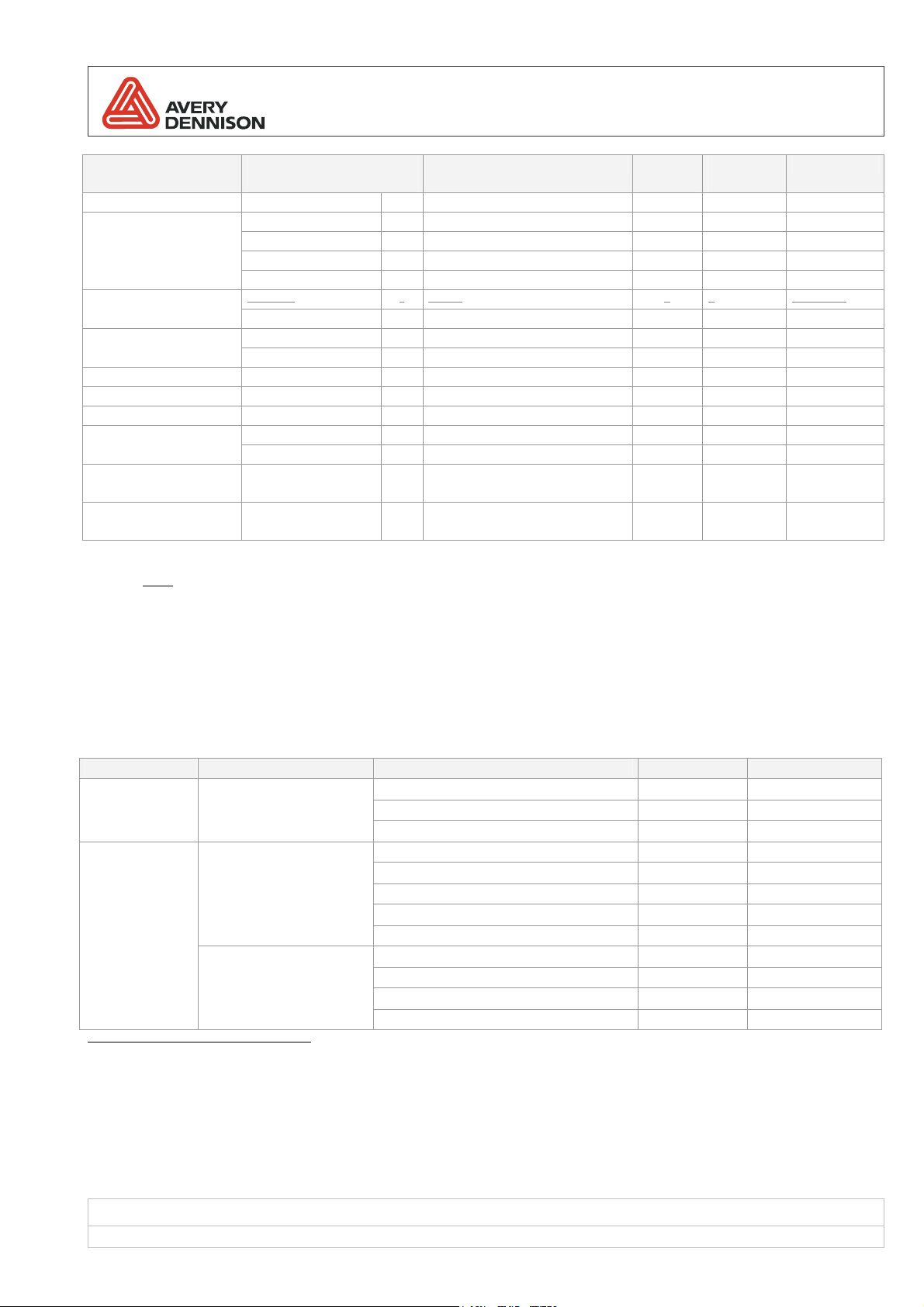
2.4.2
Definitions:
– Mechanical distances –
PH-CT: distance from print head (dot-line) to knife (cutting position)
PH-TB: distance from print head (dot-line) to tear bar (tear off edge)
PH-CA: distance from print head (dot-line) to center of printers RFID antenna
PH-DE: distance from print head (dot-line) to dispensing edge
– Mechanical restrictions –
MBF: maximum back-feed distance (without losing “grip” or ribbon wrinkling)
– Label/Inlay specific / depending distances –
LA: inlay / label specific distance from top of label to leading edge of inlay antenna
ILG: label specific inter label gap (distance between two subsequent inlays)
OPA: RFID operating point measured from leading edge of antenna of inlay
OPL: RFID operating point measured from leading edge of label (=> antenna offset)
Figure 1 shows a label web in the paper path of the printer with symbolic dimensions.
Mechanical specifications / restrictions
Figure 1: mechanical dimensions of the paper path (and label)
Revision: 13 Date: 31 August 2009
Page 11 of 53
Page 12
HowToRFID
Printer PH-CT [mm] PH-TB [mm] PH-CA [mm] PH-DE [mm] MBF [mm]
64-0X 17.13 10.50 62.00 48.50
AP 5.4 17.00 10.00 46.50 16
ALX 92x / DPM n/a n/a 50.00 24.20 (short
dispensing
edge)
39.80 (long
dispensing
edge)
Table 3 –Paper path dimensions of printer relevant for RFID
ca. 100
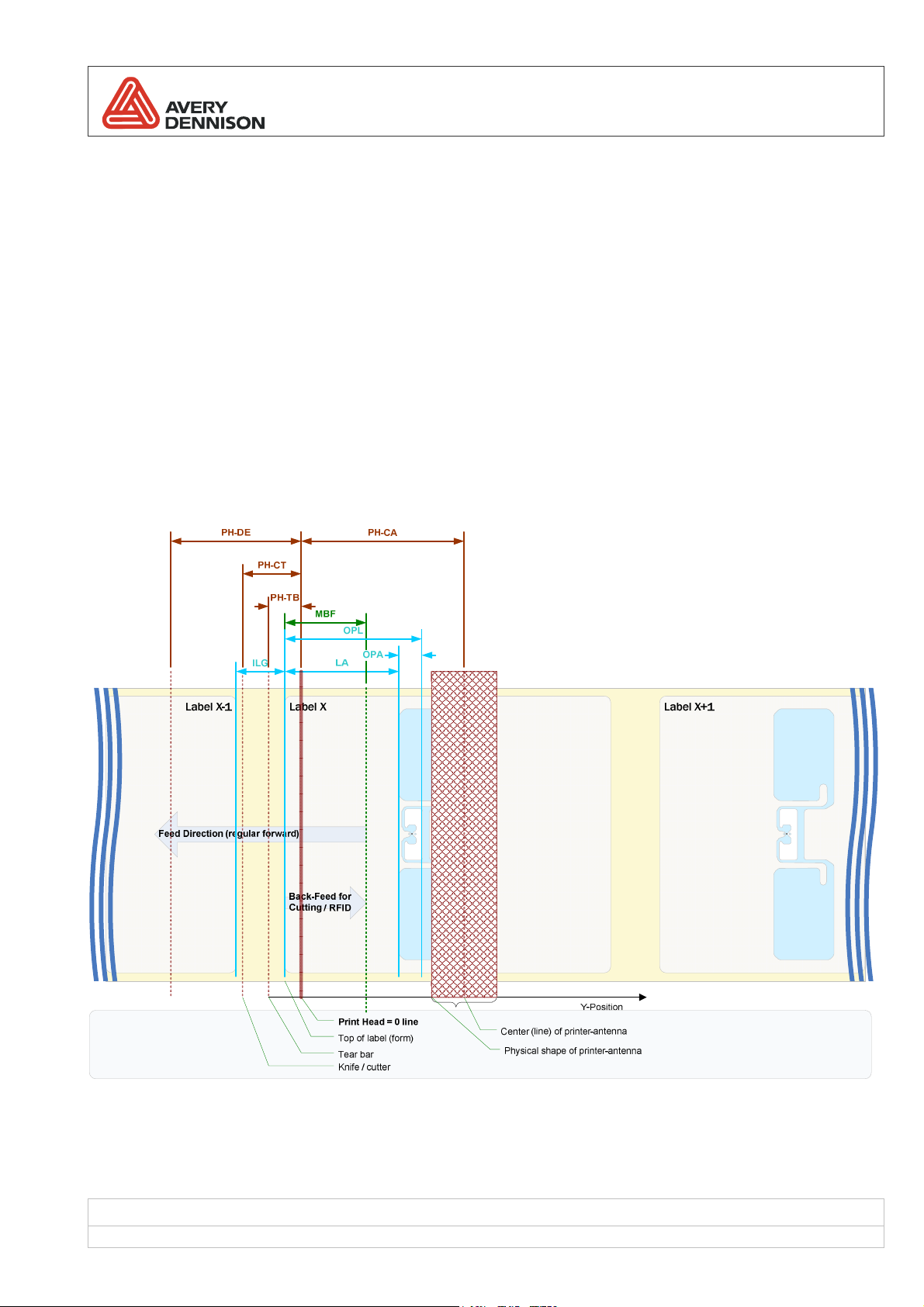
2.4.3
Inlay position / Tag antenna coupling
Smart labels with RFID functionality are treated by the printer in a two phase process. At first RFID functionality is
executed and afterwards the regular print processing is made. To communicate with an RFID transponder it has to
be in the range (RF field) of the built in reader antenna and it must be the only tag in range. For this purpose the
Easy Plug command #IM has been extended with a parameter called RFID antenna offset. It defines the distance
between label start and optimal coupling point position. In other words, it determines how much the label needs to
be back feed to bring the transponder in the right position near the printer’s antenna.
Figure 2: positioning at label start
Revision: 13 Date: 31 August 2009
Page 12 of 53
Page 13
HowToRFID
Material Feed Direction
Label X-1 Label X Label X+1
1
Label X-1 Label X Label X+1
2
Label X-1 Label X Label X+1
3
Label X-1 Label X Label X+1
0123456789
4
ABCD (1234)
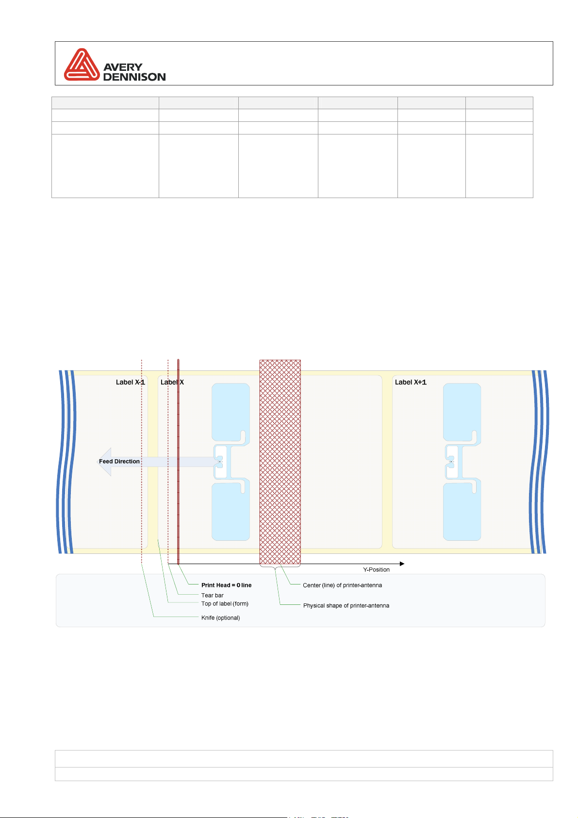
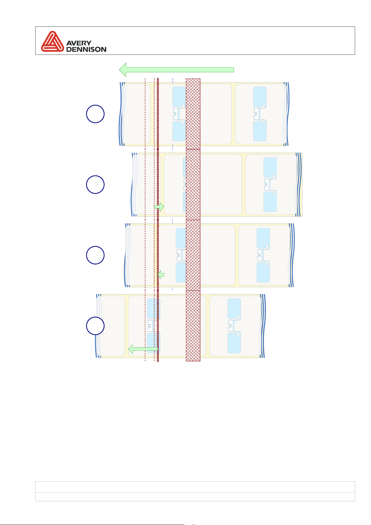
Figure 3: processing steps of RFID encoding and label printing:
(1) resting position before start of RFID processing / printing
(2) back-feeding of label to the RFID encoding position (move inlay antenna to best-match position with printer
antenna)
(3) forward-feeding to bring start of label to dot line again (after RFID encoding)
(4) label printing in progress
Label positioning is the first action that takes place when processing a RFID label. Afterwards all RFID commands
are executed. When this is finished the label is repositioned to the beginning and all other printing actions are
executed.
Revision: 13 Date: 31 August 2009
Page 13 of 53
Page 14

HowToRFID
2.4.4
RFID starter kits
Avery Dennison offers RFID starter kits for the RFID printers. The starter kit contains also RFID supplies (labels).
For those supplies a pre qualification was made and the parameters for adjusting the printer to this supply are
available on the supply data sheet. The supply is referenced by an Avery article number. If there is no data sheet
included in the supply package, please ask your reseller or the technical support team for the supply data sheets.
Application requires the use of another inlay?
Avery Dennison publishes a document called “RFID Label Design & Printer Setup Guide”. The content of this
document is the essential extract of an intensive inlay qualification process. Goal of that process is, to find the
optimum label design parameters and printer setup parameters for an “optimized” label.
It’s highly recommended to use the parameters determined in the RFID inlay qualification process for the
processing of inlays in the printer.
For further details see section 4.2…
Using pre qualified supplies
2.4.5
Finding and defining the optimum coupling position (the “Hotspot”)
If the position of the hotspot measured from the beginning of the label is close to the relative position of the
antenna, little or no material movement between RFID processing and printing is necessary. This leads to an
optimal performance (throughput).
But, due to shielding / coverage reasons this may be not the best position for coupling!
UHF Technology
Printer Position of the center-line of the
UHF antenna relative to print head
(dot-line)
64-0X 62.0 mm +/- 48 mm
AP 5.4 46.5 mm +/- 16 mm
ALX 92x / DPM 50.0 mm
PEM n/a n/a
Table 4 – Antenna position relative to print head
Inlay placement window (+/offset from ideal position)
TBD (depending on dispensing
mode, rewinder etc.)
HF Technology
Printer Position of the center-line of the HF antenna relative to
print head (dot-line)
64-0X 62 mm
AP 5.4 n/a
ALX 92x / DPM 80 mm
PEM n/a
Table 5 – Antenna position relative to print head
Revision: 13 Date: 31 August 2009
Page 14 of 53
Page 15

HowToRFID
2.4.6
How to execute the hotspot-/profile test
To find an optimized antenna position, execute a “Hotspot test”. To execute a hotspot test use the menu item
“RFID Parameters / Hotspot test”.
Repeat the Hotspot test with different power level settings to find a combination of power level and antenna offset
which makes sure only the inlay in direct contact (located nearby) the antenna is processed and no adjacent read
or writes occur.
With attenuation power control (firmware version <= X.33):
Start with minimum power (high value, for example 245) and increase the power (decrease the power level value)
in steps of 5 or 10. Starting with low power identifies the most sensitive position.
With dBm power control (firmware version >= X.34):
Start with minimum power (low value, for example 5) and increase the power (increase the power level value) in
steps of 5. Starting with low power identifies the most sensitive position.
How to hotspot-/profile test works
Hotspot-/Profile test
At the beginning the printer positions the start of label (top of label) to the center of the printer’s antenna. During the
test the label gets feed stepwise by 2.0 mm until the end of the label reaches the position of the printers antenna.
The length of the label is determined by the current material length setting.
At each position the printer tries to write an EPC code to the tag with different power levels. The range of the power
level to be tested is determined by the current power level and ranges from current value -5 dBm ... current value +
5 dBm. At each test point (position / power level) a single write attempt is made and the result (success or failure)
gets recorded into the printer’s memory.
After the complete label has been processed, a test result graph is generated and printed to the same or a
following label. For short labels the printout can be printed to a following label due to slight slippage during feeding
and gap detection. If it’s required to print exactly to the same label, decreasing the material length by 1..3 mm may
help, especially if material length was adjusted with the auto-calibrate feature.
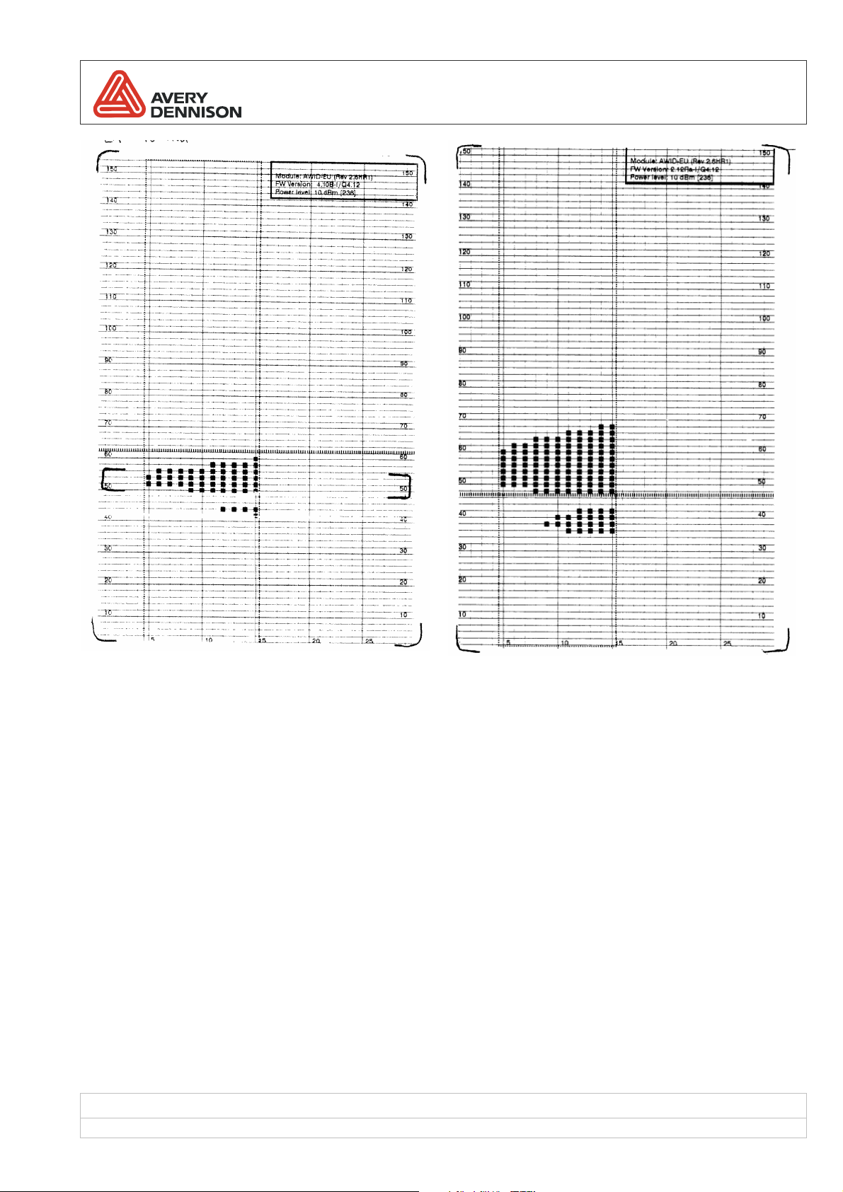
Hot to read the result printout
The Y-axis (feeding direction) direction shows the position (unit mm) of the “hotspot” relative to top of label (begin
of label = 0 mm). The position determined during analysis of the printout can be transferred 1:1 to the antennaoffset parameter of the EasyPlug #IM command.
The X-axis (across the label) shows the power level (unit dBm). Power level increases from left to right side (0 dBm
at the left side ca. 30 dBm on the right side). Possible range depends from the capabilities of the RFID reader
module.
A black dot (filled square) shows a successful encoding for the related position and power level. The complete
tested range (position and power level) is indicated by the dotted line rectangle.
Current settings of the RFID components (RFID reader module, firmware version, current power level) are shown in
the top right corner.
The thick dotted line across the label shows the position of the printer’s antenna (if TOL is at the print-head).
Revision: 13 Date: 31 August 2009
Page 15 of 53
Page 16
HowToRFID
AD 222 in 64-05 with AWID-EU reader module AD-222 in AP 5.4 AWID-EU reader module
How to select the antenna offset
Choose a region where at least 3 x 3 adjacent “dots” of the matrix show a successful writing. If there is more then
one region like this, choose one which is located near the center-line of the antenna in the printer (see 2.4.4). The
goal is to avoid unnecessary web movement to reach optimum throughput and to avoid problems from “loosing” the
material if a cutter or tearbar is used.
A note regarding the power level: please keep in mind “less is better”! Only use a high power level if there is no
large enough area in a low power level region for safe and reliable operation.
Revision: 13 Date: 31 August 2009
Page 16 of 53
Page 17

HowToRFID
Limitations of this test
The built-in hotspot-/profile test was designed to be a customer self-care instrument. It can not completely replace
the advanced and more detailed tests made during the inlay qualification process done by Avery Dennison. If
published printer settings are available for a specific inlay, it’s highly recommend to use that settings before making
several trials with self determined settings. During the inlay qualification process a lot more inlays are tested to
intercept possible performance decreases from placement and sensitivity tolerances. A test with a single RFID
label can never provide that level of reliability…
The following limitations apply:
1) The test can not determine write zones (sensitive zones) located before or after the label itself. For very short
labels where the inlay is located near top of label and / or near the end of the label (for example pure paper
faced inlays), the sensitive zones might be located in before or after the inlay.
2) The test can not determine whether crosstalk effects have an influence. Crosstalk effects: while trying to write
to the inlay nearest the printer’s antenna, the radio energy is reflected or otherwise forwarded to the adjacent
inlays (on the web) and those inlays respond to the write attempt to. For details about cross talk/adjacency
problems see section 4.2.
3) The material length must be adjusted to meet the real material length (+/-10%), otherwise the printout fails. If
the inlay is located near TOL in a (very) long label, it’s required to run the test for the whole label even if it’s
expectable to have a large “dead” zone at the end.
2.4.7
Processing failures (errors) – Invalidating labels
For HF technology the RFID command execution starts with selecting the tag under the antenna. When tag
selection fails, it is retried like every RFID command that can fail. After a defined number of retries (compare RFID
parameter „Number of CMD retries“) it is concluded that there is no transponder under the antenna or the
transponder is defective. This is documented by invalidating the label with printing a characteristic pattern
(diagonal bars) on the label.
Afterwards no more printing is done for this label and the next label is tried. This is repeated until a valid
transponder is found or a defined limit of invalid transponder in sequence is reached (defined in parameter „Max
tags to stop“).
When this maximum number of invalid labels in sequence is detected, job processing is stopped. It is assumed that
a certain number of invalid transponder is an indicator for a severe problem that has to be solved first. Afterwards
job processing can be continued.
Revision: 13 Date: 31 August 2009
Page 17 of 53
Page 18

HowToRFID
For UHF technology the step “selecting the tag” is skipped (not necessary). The RFID processing starts
immediately with the requested write or read operations. If one of the operations fails (is not successful) the label
gets invalidated in the same way is described for HF technology.
2.4.8
Processing failures (errors) – Bad tag signaling
As mentioned before if the RFID processing fails the label is invalidate. For automated processes this is not
sufficient because it must be made sure in not-encoded label is not released (forwarded) into a further process. As
a prerequisite for this requirement a print and apply system must signal RFID processing errors via a control
interface.
A mechanical unit for removal of invalid labels (also called bad tags) can be triggered by that signal and remove the
invalid label from the processing line.
BTS on the Applicator Interface
For the print and apply system ALX 924 / ALX 926 the bad tag signal is available on the applicator interface as
output signal “BTS”. For details see [AI-Manual].
An optional Bad Tag Separator can be attached to the ALX to remove the invalid labels by sticking them on a
waste roll.
Alternative solutions
Please note: the BTS is not available on the USI.
2.4.9
Statistics
There is information about RFID operations in a printable status. It tells you for example how many operations of
each type have been processed and how many of them have failed (compare).
RFID Status
System version V5.33
Printer type Avery 64-05
Nr. Cmd retries 3
Nr invalid tags 3
Statistics
Nr of tags 707
Nr invalid tags 72
Scrap rate 10.2 %
Total Nr SELECT 755
Invalid SELECT 17 %
Total Nr Read 730
Invalid Read 730
Total Nr WRITES 507
Invalid WRITE 29 %
…
Aug 01 2008
Figure 4: example of printable RFID information
Revision: 13 Date: 31 August 2009
Page 18 of 53
Page 19

HowToRFID
2.5 Using a cutter
There is a limitation by moving not more than 48 mm backwards for 64-0x and 17 mm for AP 5.4. For relevant
antenna positions in different machine/printer types see 2.4.4
This limitation must be considered if labels with a non-optimal inlay placement shall become processed. The inlay
must be placed behind the optimal position (away from top of label) to prevent additional back feeding for reaching
the RFID operation position. The optimal inlay position depends from the printer type and the inlay itself. Optimal
placement data for most common inlays is available on request.
Printer type Distance dotline / cutter
AP 5.4 17.00 mm
64 series 17.15 mm
Table 6 – Distances between dot line of print-head and cutter (cut line)
Revision: 13 Date: 31 August 2009
Page 19 of 53
Page 20

HowToRFID
3 Prepare the printer
3.1 Configuration
3.1.1
Activating the RFID-option
The very first thing to do for using RFID in an AVERY printer is to activate the RFID option. To activate RFID set
parameter „Interface Parameter / OPTIONS / RFID Option“ to the value of appropriate COM interface (internal
serial RS232 interface). After confirming the entry the printer reboots itself with appropriate settings for internal use
of COM.
Printer type RFID option (internal connection)
AP 5.4 (Marlin CPU board) Serial Com3
AP 5.4 (Redfin CPU board / Marlin MLK) Serial Com4
64 series / DPM / ALX 92x (Gen 2 CPU board) Serial Com2
64 series “High Performance” / DPM / ALX 92x (Gen 3 /
Dolphin CPU board)
Table 7 – Serial port for RFID option
3.1.2
Material depending RFID parameters
Serial Com4
3.1.2.1 Power level
The Power level setting is a very critical part of the whole setup of an RFID printer. The Power level setting controls
the output power of the radio module of the RFID reader. The output power must be adjusted an a way that the
inlay to be processed (in direct coupling with the antenna) gets enough “radio” energy to be able to respond to the
request from the RFID reader – but on the other side to avoid the activation of adjacent tags (resulting in unwanted
reads or writes from multiple transponders).
To find the right setting can be a tricky and time consuming process. It depends mainly from the dimensions of the
material especially the pitch between inlays and the type of inlay used.
To ease this process Avery Dennison has introduced a RFID inlay qualification process, were popular transponders
/ inlays get tested in the lab. See section 4.2 for details.
There is a simple rule of thumb: adjust to the lowest power level which gives constant success. Applying to much
power leads to problems caused by reflections and adjacent reads/writes.
Please note: the RF transmit power depends from the built-in RFID reader module, which is a different one for the
different regulatory regions (EU/ETSI, US/FCC, Korea).
Power control changing an “attenuation” value
Up to and including printer firmware versions Vx.33, the power level is adjusted by a numerical value which controls
the attenuation of the transmitted radio signal. Resultant in reverse logic: high numerical value => low power, low
numerical value => high power. The output power doesn’t follow a linear curve, especially in the range of 255 –
200. Therefore changes in small steps may result in very large differences in read / write success.
In most technical documents radio output power is measured in the unit of the physical power level mili watts (mW)
and is presented as logarithmic scaled value in dBm.
Revision: 13 Date: 31 August 2009
Page 20 of 53
Page 21

HowToRFID
The following table provides the correlation between the numerical setting and the physical value for the EU
module (C1616, hardware Rev A 2.6HR1) and the US module (C1184, hardware Rev E).
C1616 – EU Module (Rev A 2.6HR1) C1183 – US Module (Rev E)
Please note: range 0..30 dBm
Power dBm Attenuation Value
0 255
1 253
2 251
3 248
4 246
5 245
6 243
7 241
8 240
9 238
10 236
11 234
12 232
13 231
14 230
15 227
16 223
17 221
18 218
19 213
20 208
21 204
22 199
23 190
24 182
25 170
26 160
27 140
28 110
29 70
Please note: range 18..30 dBm
Power dBm Attenuation Value
18 255
19 230
20 200
21 160
22 140
23 110
24 90
25 70
26 55
27 40
28 25
29 10
30 0
Power Curve - AWID MPR 15xx EU, Rev A 2.6HR1, FW 4.07 I/Q4.06
35
30
25
20
15
Power Output (dBm)
10
5
0
0 25 50 75 1 00 125 150 175 200 225 250 275
-5
Power Setting (attenuation value)
Measured Power
35
30
25
20
15
Power Output (dBm)
10
5
0
0 25 50 75 100 125 150 175 200 225 250 275
Power Curve - AWID MPR 1510-AE RM Rev E (FCC) , FW 2.33B I/Q4.11
Measured Power
Power Setting (attenuation value)
Table 8 – Power level to attenuation mapping tables
As visible from the table and charts above there are big differences in the range of adjustable power for the
EU/ETSI and US/FCC modules. So a power level setting (attenuation value) for the EU module can not be simply
transferred to the US module.
Revision: 13 Date: 31 August 2009
Page 21 of 53
Page 22

HowToRFID
Power control by “dBm” scaled values
Starting with printer firmware version Vx.34 the direct control of the “attenuation” parameter was removed and a
new parameter “Power level in dBm” was introduced. The printer detects the built-in RFID reader module type +
hardware revision and uses an internal mapping table from the value in dBm to the attenuation value to be send to
the RFID reader module. To make it comparable with previously used settings the menu entry for power level
adjustment shows the resulting attenuation value from the selected dBm value.
The dBm value uses regular logic (low value = low power) and is in depended from the built-in module.
Please note: For applications using the EasyPlug #PC command for adjusting the power level as part of the printer
job an adaptation is needed. The parameter ID for the power level has changed and values need to be converted
to dBm. It’s not anymore possible to directly change the attenuation value.
Power control via EasyPlug
The RFID power level is adjustable via the EasyPlug #PC command. Changing the value shows immediate effect.
(Also during still running jobs, so be careful if working with different supplies.)
Parameter ID
− printer firmware version <= x.33: 5202 -> attenuation value
− printer firmware version >= x.34: 5208 -> dBm value
3.1.2.2 Antenna offset
The antenna offset is defined inside an EasyPlug job using the #IM command. Section 2.4 describes why you need
to set the offset and how to find the hotspot.
If you are using a label based on a qualified inlay, the value for the hotspot is mostly identical to the physical
antenna position in the printer (when label producer follows recommended inlay placement position). See section
4.2 for how to calculate the antenna offset for a deviating inlay placement.
3.1.3
Parameters for error handling
They can be found in the „RFID Parameter“ menu. Their meaning is
Parameter Effects
Max tags to stop Number of transponders (tags) that have to be invalid in sequence before a printing job is stopped.
This parameter exists because of the assumption that a certain number of invalid transponders in
sequence indicate a severe problem. After solving this problem the job can be continued.
Nr of CMD retries Number of internal RFID command retries (sending a command to the RFID reader module once
again of negative status is reported by the RFID reader module) before a fail is reported.
For HF technology especially SELECT retries are important when printer is used in noisy
environments.
Try Times UHF technology / AWID RFID reader module only:
This value controls how often the RFID reader module itself tries to perform a requested RFID
operation (read / write) until an error is reported. Setting a high value will result in lower throughput
in the case of bad tags or general non-matching RFID processing parameters (power level,
antenna offset).
The default value is set to 10 to get best throughput.
Increase this value if you have a poor yield rate resulting from a noisy environment.
Revision: 13 Date: 31 August 2009
Page 22 of 53
Page 23

HowToRFID
3.1.4
Another useful feature that can be activated on demand is “Chip protection”. Chips are part of the RFID inlay inside
a smart label. Most often they are much thicker than label material. Printing means putting pressure and heat to foil
and label. This might damage the chip. To prevent damage to the area where the chip resides, the print head can
be lifted in this area. Any printed output within the protected area is prevented.
Different implementations of chip protection
In printers without the capability for lifting the print head the chip protection features defines an unprintable area.
Any output in the chip protection area is suppressed so it stays blank. If you don’t use the chip protection keep in
mind that printing at the edges and on the inlay itself results in lower print quality due to the changes of thickness of
material.
Printer Effects
AP 5.4 Chip protection area is defined as unprintable area.
64-0x Chip protection area is defined as unprintable area.
DPM / ALX Same as 64-0x
PEM n/a
Chip protection
The head can’t be lifted.
The chip protection feature can be used to avoid printing inside the area of the inlay which may
result in lower printing quality because of the alternating thickness.
Additionally the head will be lifted before the start of the chip protection area to ensure the path is
open when the chip passes the print line. The area is enlarged by the way the head physically
needs to lift completely and go back down. The enlargement depends from the print speed (higher
speed – higher enlargement)
How to control the chip protection feature
EasyPlug: the #IM command gives full control over the chip protection feature. A value of 0 for the chip
position/offset disables the chip protection feature, a value greater than zero activates the chip protection feature.
Providing no value is identical to providing zero (which disables the feature).
Using the menu:
Parameter Effects
Chip protection Enable this parameter if you would like to activate chip protection. (See note below)
Chip size Visible if and only if parameter “Chip protection” is enabled. Defines size of area in regard to
printing direction that is excluded from printing.
For calculation of the protected area the chip size is centered around the the chip position (so the
size counts one times only) + a print speed depending offset for head up and down movement.
Chip offset Visible if and only if parameter “Chip protection” is enabled. The offset defines the beginning of the
chip protection area.
Note: The setting from the #IM command has highest priority. It activates (> 0) or deactivates (=0) the chip
protection feature depending from its value. After the #IM command was used in a job the menu reflects the last
setting from #IM command. De facto the menu setting “chip protection” can be seen as an informative / read only
parameter.
3.1.5
Recommendations for web / material handling
Adjusting the material pressure rollers
Please take care the pressure rollers don’t run over the RFID chip. Doing so will destroy the RFID inlays.
Revision: 13 Date: 31 August 2009
Page 23 of 53
Page 24

HowToRFID
Adjusting the punch level
The punch detection for RFID labels can be a little bit tricky due to the different “darkness” of the different zones of
in RFID label: liner only, liner + paper, liner + paper + RFID inlay plastics, liner + paper + RFID inlay antenna.
If it is not possible with the automatic punch detection mode to get reliable punch detection, the manual punch
detection might help.
Set the parameter “Punch mode” to “manual” and adjust the parameter “Punch level” to a value which is around 15
units higher then the measurement value when liner + paper (without inlay) is visible for the punch sensor.
For details about that please see the printer manual.
3.2 Additional support functions
3.2.1
Menu item Function
Tag type (*1) Choose tag type that is assumed as base for “Read EPC” / “Write EPC”
Read EPC Function to read and display EPC from smart label near printer antenna. Only smart labels with
Write EPC Function to write EPC to smart label near printer antenna. Only smart labels with chosen tag type
Hotspot tests Performs a test to find the sensitive write zones of the inlay (label). See 2.4.5 for details.
Functions for testing purpose
chosen tag type are considered.
The function stays in an endless loop until the user cancels with the “ESC” key. In each loop a
read attempt is made and if a tag could be read the EPC is displayed otherwise in line of “---“
chars.
are considered. The EPC that is written is created by printer firmware.
The function stays in an endless loop until the user cancels with the “ESC” key. In each loop a
write attempt is made and if the EPC could be written to an tag “OK” is displayed otherwise “fail”.
Each loop is signaled by a moving star in the progress bar.
The EPC which becomes written is fixed, but in every loop the first 16 bits are chosen randomly.
(*1) supported only in semi custom printer firmware. Standard printer firmware only supports EPC Gen2 protocol
(tag type) for UHF technology.
3.2.2
Menu item Function
Module Designator to identify RFID reader module that is mounted inside the printer.
FW Version Version number to identify firmware that is used by internal RFID reader module.
For information
Printer firmware version <= Vx.33:
This information is quasi static – it depends from the detected reader, but is not queried in a direct
way from the reader module. Unfortunately it doesn’t reflect the hardware revision which is an in
important for firmware updates.
Printer firmware version >= Vx.34:
During boot time the printer identifiers the built-in RFID reader module.
For the AWID reader (UHF technology) module The value shows the module type (“AWID”), the
regulatory region identifier (“EU”, “US”) and the hardware revision level (“Rev 2.6HR1”, “Rev E”).
For the HF technology it shows only the module type (“FEIG”).
Both values are also accessible via remote parameter query mechanisms and in the “setup” file.
Revision: 13 Date: 31 August 2009
Page 24 of 53
Page 25

HowToRFID
3.3 AWID RFID module firmware update
3.3.1
Update procedure
Note: firmware update for RFID reader module is handled like normal printer firmware update (compare printer
service manual), especially “*.ihb” files are treated like “*.s3b” files
4) Update printer firmware to appropriate version named in column “printer firmware”.
5) Update main reader firmware to version in same row (e.g. 4.10B for EU region and Gen2) - printer resets after
finishing update
6) Update I chip firmware to version in same row (e.g. 4.06) - printer resets after finishing update
7) Switch off/on printer
8) Update Q chip firmware to version in same row (e.g. 4.06) - printer resets after finishing update
9) Switch off/on printer
10) Check for function by activating “Read EPC” and “Write EPC” in menu RFID parameter
Caution
− Check hardware compatibility list (Never upgrade a module with FW 2.xxy to 4.xxy)
− Take care, do not switch off printer while updating
− main download takes about 15 minutes (on AP5.4)
− I/Q chip download takes about 5 minutes each (on AP5.4)
Revision: 13 Date: 31 August 2009
Page 25 of 53
Page 26

HowToRFID
3.3.2
3.3.2.1 Printer firmware / Reader module firmware
Applicable for UHF printer only (with RFID module from AWID). Bold highlighted versions are the most current
approved and recommended versions.
Main
2.05M ?? original version < V3.40 none
C1183 – US Versions (Rev E)
2.17M 2.10 split version US 915 MHz >= V3.40 >= V2.50
2.24M 4.03 adds EPC class 1 Gen2 US >= V4.00X1 >= V3.00X1
2.28M 4.03 Gen2 US with R/W user data
2.33M 4.11
C1616 – EU Versions (Rev 2.6HR1)
2.02Rd 4.06 Do not use – upgrade to 4.10B Not compatible Not compatible
2.05B 2.10 split version EU 869 MHz >= V3.40 >= V2.50
2.11B 4.03 adds EPC class 1 Gen2 EU >= V4.00X1 >= V3.00X1
4.07B 4.06 Gen2 EU with R/W user data >= V4.22X01 (Gen2)
4.10B 4.06 Data integrity issue for EPC Gen2 Monza 2
2.12Ra 4.12
C1674 – Korea Versions (Rev 2.6H2)
4.45Me 4.11 full support of 512 bit user memory of NXP
4.85Me 4.12
Dependencies
Version
I/Q
Purpose
Gen2 US
(recommend version for US)
chips corrected
Supports 240-bit EPC
Data integrity issue for NXP U-Code G2XL
/ G2XM chips corrected
(recommend version for EU)
U-Code G2XM chips
Supports 240-bit EPCs
Data integrity issue for NXP U-Code G2XL
/ G2XM chips corrected
(recommend version for EU)
Printer firmware Version
640x / ALX 92X / DPM AP5.4
>= V4.22X01 (Gen2)
>= V5.02X01 (Gen3)
Semi custom firmware
>= V4.22X01 (Gen2)
>= V5.02X01 (Gen3)
Standard firmware
>= V4.33 (Gen3)
>= V5.33 (Gen3)
>= V5.02X01 (Gen3)
Semi custom firmware
>= V4.22X01 (Gen2)
>= V5.02X01 (Gen3)
Standard firmware
>= V4.33 (Gen3)
>= V5.33 (Gen3)
Standard firmware
>= V4.33 (Gen3)
>= V5.33 (Gen3)
Semi custom firmware
>= V4.22X01 (Gen2)
>= V5.02X01 (Gen3)
Standard firmware
>= V4.33 (Gen3)
>= V5.33 (Gen3)
Standard firmware
>= V4.33 (Gen3)
>= V5.33 (Gen3)
>= V3.22X01
Semi custom firmware
>= V3.22X01
Standard firmware
>= V3.33 (Gen3)
>= V3.22X01
Semi custom firmware
>= V3.22X01
Standard firmware
>= V3.33 (Gen3)
Standard firmware
>= V3.33 (Gen3)
Semi custom firmware
>= V3.22X01
Standard firmware
>= V3.33 (Gen3)
Standard firmware
>= V3.33 (Gen3)
Table 9 – AWID firmware versions
Revision: 13 Date: 31 August 2009
Page 26 of 53
Page 27

HowToRFID
3.3.2.2 Hardware compatibility list (AWID reader modules only)
Region
Frequency
Article number
US
902-928MHz
C1183
EU
869.525MHz
C1616
Identifier on module Approved Firmware
UHF (902-928 MHz)
MPR 1510AE-RM REV: E
and/or
P/N: MPR1510AE-RM
UHF (869.525 MHz)
a) REV:H and/or P/N: MPR1580AH-RM
b) MPR1580A-RM REV: A and HW: 2.6HR1
c) 251060-001, Rev: A and HW 2.6HR1
2.33M + I/Q 4.11
2.12Ra + I/Q 4.12
4.10B + I/Q 4.06
4.07B + I/Q 4.06
Korea
910-914 MHz
C1674
Table 10 – AWID hardware compatibility list
UHF (902-928 MHz)
MPR-1510AH. RM
Rev H2
4.85Me + I/Q 4.12
Revision: 13 Date: 31 August 2009
Page 27 of 53
Page 28

HowToRFID
4 RFID Transponder / tags / inlays
4.1 Memory layout (data fields) of RFID Tags
4.1.1
HF Technology
HF Technology is based on a flat memory model without separation into specialized memory areas. All data is
organized as blocks of memory with equal size.
Note: a block of memory can only be written as a whole. Write operations where the length of data provided is not a
multiple of the size of a block are padded with 00 bytes.
The data type ID is used in commands for reading or writing data to select the field of tag where the operation
should work with.
Field
[data type id]
Block data (User
data) [0]
UID [1]
EAS Bit
AFI [6]
DSFID [8]
Table 11 – Data fields of HF tags
Contents / function Size in Bits (Bytes) Read / Write
access
− is organized in blocks of 4 bytes (depending from chip
type)
− size varies (depending from chip type)
− blocks can by access only as a whole
− called Unique Identifier
− is a tag identifier (contains a chip manufacturer ID, a chip
type ID and a serial number)
− is defined in [ISO15693]
− used in electronic article surveillance (EAS) applications
− it a single bit which can be set or cleared (not set)
− can be locked permanently which blocks any future
modification attempt
− AFI = Application Family Identifier
− can be used to filter out non application specific tags in
inventory operations
− is defined in [ISO15693]
− DSFID = Data Storage Format Identifier
− is defined in [ISO15693]
See Table 1 –
Supported
transponder types
64 (8)
1 Write / Lock
8 (1) Write
HF: 8 (1) Read / Write
Read / Write
Read only
4.1.2
UHF Technology (EPC tags)
The data type id is used in commands for reading or writing data to select the field of tag where the operation
should work with.
Field
[data type ID]
EPC [2]
TID [1]
Revision: 13 Date: 31 August 2009
Contents / function Size in Bits (Bytes) Read / Write
access
− called Electronic Product Code
− is a product identifier
− is defined in [EPC1]
− called Tag Identifier
− is a tag identifier (contains a chip manufacturer ID, a chip
type ID and optional a serial number)
− is defined in [ISO15693] + [EPC1]
96 (12)
64 (8)
up to 240 (30)
32 (4)
64 (8)
depending from
manufacturer
Read / Write
Read only
Page 28 of 53
Page 29

HowToRFID
Field
[data type ID]
User data [0]
Kill password [3]
Access password
[4]
Memory bank(s)
[5]
AFI [6]
Memory Block [7]
Table 12 – Data fields of UHF / EPC Gen 2 tags
Contents / function Size in Bits (Bytes) Read / Write
− also called user memory
− is organized in blocks of 2 bytes
− size varies (depending from chip type) from 0 to X
− this password must be referenced when using “Kill tag”
command
− must be 4 bytes
− is defined in [EPC3]
− this password must be used to authorize certain access to
tag memory e.g. locking and unlocking memory
− must be 4 bytes
− is defined in [EPC3]
− a memory bank presents the physical memory area of a
tag
− banks are defined as follows:
− 0: Access + Kill password
− 1: EPC
− 2: TID
− 3: User data
Direct access to a memory bank is depreciated since behavior
is undefined (behavior depends from size of memory bank
areas of different tags and additionally depends from RFID
reader firmware module.
A direct read or write access to a memory bank should only be
considered if there is no direct way to access a specific
information
Note: some memory banks may be unreadable due to security
restrictions
− AFI = Application Family Identifier
− is a part of PC (Protocol Control) bits in the EPC memory
bank (but not part of the EPC itself)
− possible range for values: 0..511 (0x00 … 0x1FF) where
the MSB is used as identifier for a not EPC global defined
identifier, and bits to lower 8 bits are named “NSI”
(Numbering System Identifier)
− is defined in [EPC3] for UHF technology
−
− There is no field “memory block” in EPC Gen 2
transponders!
− This field-identifier is only a helper to allow EasyPlug
commands the addressing of any memory area inside the
transponders memory without being limited to the
predefined field identifiers.
− see EasyPlug command description for details
access
0
224 (28): NXP G2
512 (64): NXP G2XM
32 (4) Write only
32 (4) Write only
Vary in size Read only
9 (2)
varying Read / (Write)
Read / Write
Read / Write
Revision: 13 Date: 31 August 2009
Page 29 of 53
Page 30

4.2 Inlay qualification
HowToRFID
4.2.1
The inlay qualification process
Using only the built-in functionality of the RFID enabled printer it’s more or less difficult to find out the best settings
for the RFID parameters to process a given RFID label in a safe manner.
Furthermore some of the very important parameters are already fixed (unchangeable) if a converted RFID label is
used. That’s mainly the placement of the inlay inside the label:
a) distance from top of label in feed direction,
b) placement from the left edge of the label,
c) the orientation of the inlay (typical forms: chip first or chip trailing), and
d) the distance (pitch) between two subsequent inlays (in subsequent labels).
All of those parameters have significant influence on the performance and throughput of the encoding (and printing)
process in the printer.
To get optimum performance and throughput it’s necessary to have the inlay placed in a printer- and inlay specific
optimum position in the label. This assures well coupling between the printers antenna and the (and only that) inlay
“near” the printers antenna.
On the other side it’s important to have the right minimum pitch (distance) between to subsequent inlays to avoid
the unwanted writing (and reading) to more than one inlay at once. These unwanted side-effects are also called
“crosstalk” or “adjacency” effects.
Please note: due to the EPC being “the” unique identifier of a EPC Gen 2 transponder, it’s not detectable whether
only one or multiple transponders have been “hit” by a write operation during the encoding. This would first be
possible after a unique EPC was written to each transponder – and what a bad luck – mostly the first and only
operation to be done is to write a unique EPC into the transponder.
So the only way to ensure individual programming of the transponders with a unique EPC is, to make sure it’s only
one transponder in coupling with the printer’s antenna. This can be attained by
a) using an antenna in the printer with a small “beam width” (restricted by physical limits),
b) using as less RF transmit (output) power as possible (but still enough to turn the transponder on),
c) use metal parts inside the printers paper path as shielding,
d) use a distance (pitch) between two inlays which avoids having two inlays at the same time in the RF field of
the printers antenna, and which additionally avoids energy transmission between subsequent inlays.
Another parameter having influence on the performance of an inlay is the RF regulatory region where the printer
shall operate. This is due to
a) varying sensitivity of the inlay itself for the different frequencies used,
b) different RFID reader modules used in the printer for the different regulatory regions (EU/ETSI, US/FCC,
Korea) => different RF output/transmit power and receive sensitivity
c) frequency depending RF field characteristics of the printers antenna
Because there are so many system- and transponder (inlay) specific parameters, it’s necessary to test a selected
transponder (inlay) in the target printer before designing and producing a label for a specific application.
To avoid this high burden for system setup, Avery Dennison makes the test of several well known transponders
(inlays) in advance. The results of the tests – the recommended parameters for each transponder and printer – are
published in several ways. This all together is called the “inlay qualification process”.
Revision: 13 Date: 31 August 2009
Page 30 of 53
Page 31

HowToRFID
4.2.2
RFID Label Design & Printer Setup Guide + RFID Suppy Specifications
Avery Dennison publishes documents called “RFID Label Design & Printer Setup Guide”. The content of this
document is the essential extract of the inlay qualification process required for system setup.
There are several “RFID Label Design & Printer Setup Guides”, one for each RFID enabled printer and RF
regulatory region. So care must be taken to use the right document as reference.
Having a specific requirement in an RFID application to use transponder (inlay) A from manufacturer B, it’s often a
question to find out what RFID enabled printer is the best to meet given requirements for label design.
In this case it’s a good idea to have a look inside another type of document. Additionally there is one document
called “RFID Supply Specification” for each transponder (inlay). This document contains some more details about
the transponder / inlay and the parameters for usage in the Avery Dennison printers. The parameters for all printers
are contained in the specification for that inlay and can be easily compared. Additionally the document contains
manufacturer’s part numbers, inlay dimensions, chip data etc.
4.2.3
Terms used in the inlay specifications and related documents
Transponder / inlay placement dimensions
Dim. Definition Explanation
LA Inlay position
from top of label
“offset”
This dimension is selected to ensure best operating throughput in the printer by having the inlay at the right
position for encoding, when the top of the label is at the dot line of the print head. This dimension is printer
model specific
Please note: the distance is always to the antenna leading edge, not the chip or transponder carrier (inlay base
material). This distance is generally given with a +/- 1.5 mm tolerance (otherwise see notes).
If required, a deviating inlay position is possible, but requires adaptation of the OPL dimension and leads to
decreased throughput.
For the system specific placement window see Table 13 below.
Revision: 13 Date: 31 August 2009
Page 31 of 53
Page 32

HowToRFID
Dim. Definition Explanation
LG Horizontal inlay
placement
“x-pos”
LF Minimum inlay
pitch / distance
“pitch”
LD Minimum label
length
OPL RFID operation
position relative
to top of label
OPA RFID operation
position relative
to start of inlay
antenna
Horizontal placement of inlay relative to the left edge of the liner – physically to the inside side of the paper path
in the printer. Dimension is given with a +/- 5mm tolerance.
Coupling with the transponder changes across the width of the printer paper path. An adjustment for optimal
coupling is possible by sliding the antenna of the printer. See Table 13 for the system specific limits). But, if inlay
width (distance across the web) is much smaller than the width of the printer’s antenna (100 mm), a preadjustment through proper placement of the inlay inside the label is required. Please note: especially for the
design of narrow size tags (e.g. hang tags) this can become a challenge.
This distance ensures coupling with the transponder in the current label only. Please note that the distance is
always to the antenna leading edge, not the chip or transponder carrier (inlay base material). Distance is
generally given with a +/-- 1.5 mm tolerance (otherwise see notes).
Minimum length of the label resulting from dimension LA (inlay placement relative to top of label) and the length
of the inlay carrier (base material). Additional backup might be required to ensure a valid label construction
(depending from label converting technology).
This distance identifies the “sensitive” area of the transponder which must be located in line with the center of
printer’s antenna for optimum coupling.
Distance is given relative to top of label, as printer requires it in that way.
If a deviating LA dimension is selected the corrected value for dimension OPL can be calculated by OPL = LA +
OPA.
Similar to distance OPL, but given relative to the leading edge of the transponder’s antenna.
This value is required to recalculate OPL if a deviating placement position of the inlay from top of label (LA
value) is used.
Printer settings
Dim. Definition Explanation
OPL RFID operation
OPL dimension = parameter “Antenna-Offset” of the EasyPlug #IM command
position relative
to top of label
n/a Power level
Power Level setting: up to firmware versions x.33 the printer’s power level was adjusted by
an attenuation value which results in reverse logic (high value = low power, low value = high
power)
Starting with firmware versions x.34 the printer’s power level is adjusted in dBm (a physical
unit for the power of RF fields)
See section 3.1.2.1
4.2.4
Printer specific dimensions and restrictions
Printer Position of the center-line
of the UHF antenna relative
to print head (dot-line)
64-04/05 62 mm +/- 48 mm + 25 mm
64-06 62 mm +/- 48 mm + 50 mm
AP 5.4 46.5 mm +/- 16 mm + 15 mm
ALX 924 / DPM 50 mm
ALX 926 / DPM 50 mm
PEM n/a n/a n/a
Inlay placement window
(+/- offset from ideal
position)
depending on dispensing
mode, rewinder etc.
depending on dispensing
mode, rewinder etc.
horizontal movement
restriction of the antenna
(across the web)
+ 25 mm
+ 50 mm
Table 13 – Antenna position relative to print head
Revision: 13 Date: 31 August 2009
Page 32 of 53
Page 33

HowToRFID
5 Reading and writing RFID data using EasyPlug
5.1 Design an EASYPLUG job
5.1.1
There are several specialized RFID commands and some extended commands. Some of these commands are
mandatory and some are optional depending on your application. (For example: the #IM command is extended with
antenna offset. This is mandatory information, because a non-zero offset indicates a RFID job.)
Like every EasyPlug job a RFID jobs needs at least a
Set the RFID parameters in #IM command based on settings you identified in a material setup phase.
Note: the power level setting can’t be controlled using the #IM command. It’s accessible only via the printer menu.
If there is a need to bind the power level setting directly into an EasyPlug job this can be done using the change
system parameter command #PC (#PC5202/<Power level setting>).
5.1.2
Resulting from the continuous enhancement of RFID functionality and improvement of RFID integration with regular
printing functionality there are two different approaches to perform RFID read and write operations have been
created.
The Basics
1) #IM command: defining material parameters and RFID processing parameters (chip type, antenna offset,
optional chip protection)
2) #ER / #Q sequence with contains the layout data and the RFID operations (and optional definitions of
variables for data handling)
Concepts of data handling
1) the legacy EasyPlug commands
2) the RFID parts of the mechanism for variable data handling
Note: Using approach 2) based on the variable data handling is the preferred (because more flexible and powerful)
way to design RFID jobs.
5.1.3
The following matrix shows which EasyPlug commands may be used for specific operations to be performed.
Commands which must be used in sequence are listed with a plus sign (+), alternative commands are separated by
lines.
Please note: the commands are not listed with complete syntax – only most important RFID specific parameters
are shown.
Operation / EasyPlug command matrix
Revision: 13 Date: 31 August 2009
Page 33 of 53
Page 34

HowToRFID
Technology /
Tag type
Data field EPC Code TID
Read data field #RT//2
Write data field #RFW2
Protect (Lock)
data field
Read data field
and send data to
host
Write data field
and send data to
host
UHF
Technology
#SRF2 +
#VR/T
#SRF2 +
#VW/T
(*1)
#RFL1/2
#RFR/2 +
#RFH
#SRF2 +
#VR/T +
#SI8 +
#VW/I
#SRF2 +
#VW/T +
#SI8 +
#VW/I
EPC Class
1 Gen 2
#RT//1
#SRF1 +
#VR/T
#RFW1
#SRF1 +
#VW/T
N/A (*1)
#RFR/1 +
#RFH
#SRF1 +
#VR/T +
#SI8 +
#VW/I
#SRF1 +
#VW/T +
#SI8 +
#VW/I
User
memory
#RT//0
#SRF0 +
#VR/T
#RFW0
#SRF0 +
#VW/T
#RFL1/0
#RFR/0 +
#RFH
#SRF0 +
#VR/T +
#SI8 +
#VW/I
#SRF0 +
#VW/T +
#SI8 +
#VW/I
Access
password
--- --- #RT//6
#RFW4
#SRF4 +
#VW/T
(*1)
#RFL1/4
--- ---
#SRF4 +
#VW/T +
#SI8 +
#VW/I
Kill
password
#RFW3
#SRF3 +
#VW/T
(*1)
#RFL1/3
#SRF4 +
#VW/T +
#SI8 +
#VW/I
AFI field
#SRF6+
#VR/T
#RFW6
#SRF6+
#VW/T
--- --- N/A #RFC ----
#RFR/6+
#RFH
#SRF6+
#VR/T +
#SI8 +
#VW/I
#SRF6+
#VW/T +
#SI8 +
#VW/I
HF echnology
User
memory
#RT//0
#SRF0 +
#VR/T
#RFW0
#SRF0 +
#VW/T
#RFR/0 +
#RFH
#SRF0 +
#VR/T +
#SI8 +
#VW/I
#SRF0 +
#VW/T +
#SI8 +
#VW/I
Various
UID EAS-Bit
#RT//1
#SRF1 +
#VR/T
#RFW1
#SRF1 +
#VW/T
#RFR/1
+ #RFH
#SRF1 +
#VR/T +
#SI8 +
#VW/I
#SRF1 +
#VW/T +
#SI8 +
#VW/I
--- ---
#RFC #RFW6
--- ---
--- ---
AFI /
DSFID
field
#RFW8
Table 14 – EasyPlug commands / RFID operations matrix
--- : function / feature not supported
(*1) before the command for activation of write protection the access password must have been written to the tag
5.2 Legacy EasyPlug commands
In a RFID job you can write data to and read data from a tag. Use command RFW to write data to tags, und use
either command RT to read data from tag and print it on the label or the combination of command RFR and RFH to
get data via the defined communication interface.
These commands can be used all together mixed in one job. Data can be read in the same job when it is written to
the tag. Take care that the command that writes data must be placed before (lower line number) a read command
when this data should be read in the same job.
For the complete description of the RFID related EasyPlug commands #IM, #ER, #RT, #RFW, #RFR, #RFL, #RFH,
#RFC, #RM see “The EasyPlug manual” [A0164].
Note: Using the legacy commands is not the preferred way to read from and write data to a tag. The concept of
variable data handling gives much more flexibility for processing data before writing to the tag.
5.2.1
Operation Command(s) Notes
Read data from tag and print data
to label
Write data to tag #RFW Auto increment of numeric values isn’t implemented => use
Special commands for proprietary
tag features
Read and Write operations
#RT
variable data handling approach instead
#RFC allows control the EAS bit of HF tags
Revision: 13 Date: 31 August 2009
Page 34 of 53
Page 35

HowToRFID
5.2.2
Operation Command(s) Notes
Read data from tag and send to
host
Lock / unlock fields (memory
areas)
Measurement (Hotspot test) #RM Only supported up to version x33.
Other RFID operations
#RFR + #RFH
#RFL There is no equivalent for this operation using the variable
data handling approach.
5.3 Commands using the variable data handling mechanism
5.3.1
User defined variables act as data storage, input values for RFID write operations or buffers for holding data read
from tag.
There exist a lot of functions for manipulation of variable contents (like increment or decrement), concatenation or
truncation and conversion between different coding schemes.
All EasyPlug commands, operators and functions related to the variable data handling mechanism are described in
the EasyPlug manual [A0164].
Please see:
Definition of variables and data manipulation
Commands: #VDT, #VDS, #VDD, #VTS, #VDE
Functions: Mod10, SubStr, Length, MergeRight, MergeLeft, DayOfYear
Additional functions for data manipulation (see section 5.3.3):
Functions: DecToBin, BinToDec, HexToBin, BinToHex, DualToBin, BinToDual, PadRigth, PadLeft
5.3.2
Data coding schemes / coding scheme conversion
Data can be handled inside EasyPlug using different coding schemes as described below. Having this opportunity
makes it easy to do bit-manipulations or construct complex data fields from parts or data components. Data of any
coding scheme can be stored in a text variable because there are no special characters or something like that may
conflict with the used storage mechanism.
Important note: Data to be written to a tag must be provided in the binary coding scheme as parameter of the
#VW/T command.
Data read from the tag is stored into a variable using the binary coding scheme. Before printing to a label it may be
necessary to convert the data into the Hex (HexAscii) coding scheme.
Revision: 13 Date: 31 August 2009
Page 35 of 53
Page 36

HowToRFID
Coding scheme Description Valid characters Length
Bin (Binary) Each character in a variable
presents one physical byte
Hex (HexASCII) HexAscii encoded binary data 0-9, A-F 2 characters = 1 byte of data
Dual (BinaryASCII) Bitwise encoded binary data (MSB
first orientation)
Dec (Decimal) Decimal presentation of numbers 0-9 Variable depending from value of the
Table 15 – Data coding schemes
Examples
Any value a byte can
have (0-255)
0/1 8 characters = 1 byte of data
1 character = 1 byte of data
number
Data on tag
memory dump in Hex
Ascii notation
41 42 43 44 ABCD 41424344 01000001.01000010.
30 30 30 31 0001 30303031 00110000.00110000.
39 30 30 31 9001 39303031 00111001.00110000.
00 10 11 FF
(1) shown here as printed text on the label
(2) stands for an unprintable (non ASCII) character
(3) dots inserted for better readability
Data if directly
transferred to
Textvariable (1)(2)
Data after
conversation using
BinToHex (1)
001011FF 00000000.00010000.
Data after
conversation using
BinToDual (1)(3)
01000011.01000100
00110000.00110001
00110000.00110001
00010001.11111111
Date after
conversation using
BinToDec (1)
0
1
9001
0
More examples: see section 6.2 for examples how to use functions and data conversion.
5.3.3
Function + syntax Description
DecToBin(expression) Converts decimal part of expression into binary string of bytes. Decimal number in
BinToDec(expression) Converts expression into decimal number
HexToBin (expression) Converts expression given as hexadecimal number represented in ASCII
BinToHex (expression) Converts expression to hexadecimal string
DualToBin (expression)
BinToDual (expression) Converts expression to dual representation
PadRight(expression, character, number) Pads expression from right with given character until string length is equal to
PadLeft(expression, character, number) Pads expression from left with given character until string length is equal to number
Functions
expression must not exceed 2^64.
characters into binary representation.
HexToBin(„3161“) returns „1a“
Converts dual expression to binary representation.
BinToDual(„1a“) returns „0011000101100001“
number
PadRight(“111”,”2”,5) returns “11122”
PadLeft(“10101”,”0”,8) returns “00010101”
Table 16 – Functions for data conversion
Revision: 13 Date: 31 August 2009
Page 36 of 53
Page 37

HowToRFID
5.3.4
Reading and/or writing data requires always the use of a variable + two explicit commands
1) Define a variable using #VDT (or #VDE / #VDD)
2) define target field (or data type) with #SRF command
3) read or write data with #VR/T or #VW/T command using the variable defined in 1) or an constant expression
The source of data to be written to the tag can be any variable or any constant expression used as DATA
parameter in the #VW/T/ command.
The sink of data read from the tag can only be a text variable.
After reading data from the tag the data can be modified using the functions provided by the variable data handling
mechanism, printed to the label or sent back to the host using the EasyPlug interface.
Order of execution
RFID operations are executed in the order which is given by the EasyPlug job. All RFID operations must complete
before continuing with the regular printing of label. If there is a failure (due to an undetectable or bad RFID inlay or
a verify after write error) the label is marked as invalid and processing is repeated with the next label of the web.
Note: if an error occurs no update of incrementing fields is made.
Read and Write operations
5.3.4.1 #SRF - RFID Read / write target definition
Definition Command defines the target or source field and address of any following #VW/T or
#VR/T command
Command must be placed between #ER and #Q!
Syntax #SRFt/bfs/n/r#G RFID printer
#SRFt/bfs/n/r#G
t = int data type / field
0 = BLOCK (*1, *2)
1 = TID (EPC Gen2), or UID (HF / ISO 15963) (*3)
2 = EPC (EPC Gen2)
3 = KILL Password (EPC Gen2)
4 = ACCESS Password (EPC Gen2)
5 = MEM BANK (EPC Gen2; Note: applies to read operations only) (*2)
6 = AFI
7 = MEMBLOCK (EPC Gen2; see note address calculation) (*1,*2)
8 = DSFID (HF / ISO 15963)
Notes:
*1) “s” parameter required
Revision: 13 Date: 31 August 2009
Page 37 of 53
Page 38

#SRFt/bfs/n/r#G
opt. b = L Least significant byte of block first (default) :
= M Most significant byte of block first:
opt. f = P locking option (write protect), default: don’t’ lock
opt. s = int if data type is
HowToRFID
*2) “n” parameter required
*3) “n” parameter optional - for limiting size of data returned for read operations
Bytes of data (provided with the #VW/T command) are written on transponder
beginning with the LSB first.
Bytes of (provided with the #VW/T command) are written on transponder beginning
with the MSB first.
(not implemented yet)
BLOCK: Address of start block
MEM BANK: address / identifier of memory bank
MEMBLOCK: combination of memory bank identifier and address offset in
the memory bank
scheme for address calculation:
s = <EPC MemoryBankID> * 1000 + <BlockNumber>
EPC MemoryBankID:
0 - reserved (Acces + Kill password)
1 – EPC
2 – TID
3 – USER
otherwise ignored.
#SRFt/bfs/n/r#G
opt. n = int Number of blocks to read, used if data type is BLOCK, TID, MEMBANK, or
#SRFt/bfs/n/r#G
opt. r = int Number of read/write retries. Default defined by parameter “Nr of CMD
Default setting: 0
MEMBLOCK; ignored otherwise. Default setting: 0
for reading the field "TID" (t=1) the size parameter can be used to limit the size of
the returned data; giving no size information will return the whole content of the TID
memory bank which may contain more information than expected (depending from
RFID transponder/chip)
typical default values:
2 => read 32-bit Vendor-ID/Chip-ID
4 => read 32-bit Vendor-ID/Chip-ID + 32-bit Unique Serial Number
retries”.
Revision: 13 Date: 31 August 2009
Page 38 of 53
Page 39

HowToRFID
5.3.4.2 #VR/T – Reading data from tag
Use #VR/T/<expression> command. For details see [A0164].
5.3.4.3 #VW/T – Writing data to the tag
Use the #VW/I/<expression> command. For details see [A0164].
5.3.5
Sending data that was written to the tag or read from the tag back to the host requires the use of a variable + two
explicit commands
1) Define a variable using #VDT
2) Read data from tag using #VR/T (or write data to tag using #VW/T)
3) define response format and point on time / condition (trigger) with #SI command
4) send data with #VW/I command using the variable defined in 1)
5.3.5.1 #SI – Response format definition
Definition There is a response string made of header h and requested data that is send back to the
Command must be placed between #ER and #Q!
Syntax #SIr/n/h#G RFID printer
Sending data (read from tag) to an interface
host via EasyPlug Interface. If parameter n is different from zero the return string is
trimmed to byte count n. If respond string is less than n bytes it is filled with blanks (hex
code 0x20), otherwise respond string is truncated to fit into n bytes.
#SIr/n/h#G
r = int logical point in time concerning print control that defines when to send data
(trigger point)
1 = at start of a new EasyPlug format
2 = at restart of a previous EasyPlug format (#Q without #ER)
3 = at start of a single label operation
4 = at start of RFID operation
5 = at end of successful RFID operation(s); if read/write operations fail the
trigger doesn’t fire
6 = at start of the real print process
7 = at end of the real print process
8 = at end of a single label operation (label printed without error)
9 = at end of an EasyPlug format (#Qn label printed)
10 = at any motion control error
11 = at any RFID error (tag read or tag write error); triggered together with the
Bad Tag Signal
Revision: 13 Date: 31 August 2009
Page 39 of 53
Page 40

HowToRFID
#SIr/n/h#G
n = int number of bytes to respond
#SIr/n/h#G
h = string header used as prefix of data to respond
For details see [A0164].
5.3.5.2 #VW/I – Sending data to the host
Use the #VW/I/<expression> command. For details see [A0164].
5.3.5.3 #RFC – Special RFID commands
Definition Sends a command sequence to the RFID reader module to trigger special operations
which are not mapped / part of the regular read/write/lock operations.
The commands are specific for a RFID reader module.
Command must be placed between #ER and #Q!
Syntax #RFC<cmd>#G RFID printer
#RFC<CMD>#G
<cmd> = int Command code
--- HF Technology / FEIG reader ---
(*1) EAS features
16 set EAS bit
17 reset / clear EAS bit
18 lock EAS bit permanently
(*1) EAS features only supported by NXP I-Code chips
5.3.5.4 #RFL – Write protect (Lock) and unprotect (Unlock) memory areas
Definition Activate or disable the write protection (simple lock) of various memory areas of EPC Gen
2 tags. Before changing the write protection status first the access password must have
once been written into to access password memory of the tag with a write command
(#RFW or #SRF + #VW/T). For any attempt to change to protection status the same
password must be provided as part of the #RFL command.
Please note: the #RFL command itself doesn’t write to access password into to tag!
The #RFL command doesn’t support the permalock option specified in the EPC Gen 2
Revision: 13 Date: 31 August 2009
Page 40 of 53
Page 41

HowToRFID
standard. It implements only the write protection which can be reversed any time by
issuing a unlock command with the right access password.
Command must be placed between #ER and #Q!
Syntax #RFLa/b/c/AccessPassword#G RFID printer
#RFLa/b/c/AccessPassword#G
a = Operation
1 = lock (write protect) memory area
0 = unlock (unprotected) memory area
#RFLa/b/c/AccessPassword#G
b = Memory area selection
0 = User memory
2 = EPC
3 = Kill password
4 = Access password
#RFLa/b/BI/AccessPassword#G
B = encoding of input data
B = hex ascii encoding: for the access password 8 chars must be provided
I = encoding of input data
I = raw data (binary data): for the access password 4 chars must be provided
#RFLa/b/BI/AccessPassword#G
AccessPassword = string
EPC Gen 2 specifies the access password with a size of 32 bit (4 bytes).
Depending from the data encoding (option c) 4 or 8 characters must be provided.
Revision: 13 Date: 31 August 2009
Page 41 of 53
Page 42

HowToRFID
6 Applications / Examples
6.1 Hot spot test (UHF Technology)
Please note: the activation of the hotspot test via #RM command only supported in firmware version <= x.33.
Starting with X.34 version the test can be activated only via the menu.
Preparing the printer / print-job:
Set antenna offset to zero. Deactivate chip protection feature. Choose correct tag type (15)
Note: this is an example: Modify #IMSR for your label/tag needs. Especially label size.
sample job
#!A1
#IMSR102.0/155.0//15N/0/1/0
#ERN//
#RM0/0
#Q1#G
Please note: the hotspot test can also be initiated from the RFID parameters menu.
6.2 EPC class1 Gen2 features
6.2.1
Write / Read / Print EPC with 96bit (using variable data handling approach)
sample job
#!A1
#G-----------------------------------------------------------------------------------
#G specify material settings
#G-----------------------------------------------------------------------------------
#IMSR105/80//15N/38/3
#ER
#G-----------------------------------------------------------------------------------
#G Define variables
#G-----------------------------------------------------------------------------------
#G define your (static) EPC here using Hex ASCII encoding
#VDT/EPCDataWrite////3114F4DA34B2D05E01000000#G
#VDT/EPCDataVerify////#G
Revision: 13 Date: 31 August 2009
Page 42 of 53
Page 43

HowToRFID
#G-----------------------------------------------------------------------------------
#G Encode tag and print data
#G-----------------------------------------------------------------------------------
#SRF2
#VW/T/HexToBin(EPCDataWrite)#G
#VR/T/EPCDataVerify#G
#SF103
#J21#T7#VW/L/"EPC (1: write to tag ): "+EPCDataWrite#G
#J25#T7#VW/L/"EPC (2: verify): "+BinToHex(EPCDataVerify)#G
#G-----------------------------------------------------------------------------------
#Q1/
6.2.2
Write / Read / Print EPC with 96bit (using legacy commands)
Note: this job is composed using legacy commands. It’s not the preferred approach to to RFID processing (see
5.1.2 Concepts of data handling)
sample job
#!A1
#IMSR100/150//15/35/1
#ERN//
#G Write EPC
#RFW2/B/3///24/313456789012345678901234#G
#G Read and Print EPC
#J22#T10#RT107/0/2/B/0/2
#J5#T6#YT107/0///RFID Gen II EPC
#Q1/
6.2.3
Write / Read / Print EPC with consecutive numbering
Note: This job uses the variable data handling approach to define an auto incrementing value for the Serial number
part of the EPC. This is the only way to compose a RFID job with auto incrementing fields.
sample job
#!A1
#G-----------------------------------------------------------------------------------
#G specify material settings
#G-----------------------------------------------------------------------------------
#IMSR105/80//15N/38/3V/41
#ER
Revision: 13 Date: 31 August 2009
Page 43 of 53
Page 44

HowToRFID
#G-----------------------------------------------------------------------------------
#G Define variables
#G-----------------------------------------------------------------------------------
#VDT/EPCDataVerify////#G
#VDT/EPC_Header////00110001#G #G SSCC-96 (dual/bitwise encoded)
#VDT/EPC_Filter////000#G #G Filter value (dual/bitwise encoded), modify this to your needs!
#VDT/EPC_Partition////5#G #G (dual/bitwise encoded)
#VDT/EPC_Company////4011661#G #G Company code (decimal number) modify this to your needs!
#VDT/EPC_Unallocated////0#G
#G-----------------------------------------------------------------------------------
#G starting value for serial number, modify this to your needs!
#G value is given as a decimal number
#G-----------------------------------------------------------------------------------
#VDT/EPC_Serial//+1/1/3000000001#G
#G --- compose EPC SSCC96
#G ATTENTION: due to a change of the syntax of the PadLeft / PadRigth functions the right
#G expression/formula for the EPCDataWrite variable depending from the FW-version must
#G be selected
#G <<< syntax for FW-versions < Vx.33 >>>
#VDE/EPCDataWrite/DualToBin(
PadLeft(EPC_Header,8,0)
+PadLeft(EPC_Filter,3,0)
+PadLeft(BinToDual(DecToBin(EPC_Partition)),3,0)
+PadLeft(BinToDual(DecToBin(EPC_Company)),24,0)
+PadLeft(BinToDual(DecToBin(EPC_Serial)),34,0)
+PadLeft(BinToDual(DecToBin(EPC_Unallocated)),24,0)
)
#G <<< syntax for FW-versions >= Vx.33 >>>
#VDE/EPCDataWrite/DualToBin(
PadLeft(EPC_Header, "0", 8)
+PadLeft(EPC_Filter, "0", 3)
+PadLeft(BinToDual(DecToBin(EPC_Partition)), "0", 3)
+PadLeft(BinToDual(DecToBin(EPC_Company)), "0", 24)
+PadLeft(BinToDual(DecToBin(EPC_Serial)), "0", 34)
+PadLeft(BinToDual(DecToBin(EPC_Unallocated)), "0", 24)
)
#G <<< end of version depending expressions >>>
Revision: 13 Date: 31 August 2009
Page 44 of 53
Page 45

HowToRFID
#G-----------------------------------------------------------------------------------
#G Encode tag and print data
#G-----------------------------------------------------------------------------------
#SRF2
#VW/T/EPCDataWrite#G
#VR/T/EPCDataVerify#G
#SF103
#J21#T7#VW/L/"EPC 1-to be written : "+BinToHex(EPCDataWrite)#G
#J25#T7#VW/L/"EPC 2-verify after write: "+BinToHex(EPCDataVerify)#G
#G-----------------------------------------------------------------------------------
#G each label is encoded with a consecutive serial number starting with value set in
#G EPC_Serial
#G-----------------------------------------------------------------------------------
#Q3/
6.2.4
Write / Read / Print user data (NXP G2/G2XM, Alien Higgs 3 chips only) using legacy commands
sample job
#!A1
#PR8/8/
#G -- length/width
#G -- tag type = 15 (EPC class 1 Gen2)
#G -- tested with NXP G2 / G2XM chips from NXP (14/32 words = 28/64 bytes = 224/512 bits user data
adressed from 0..13/31)
#G -- antenna offset 60mm - adjust this to fit your needs !!
#G -- number of label to retry is 1
#IMSR100.0/67.0//15/60/1
#ERNF//
#G ---------------------
#G -- write EPC 96 bit based on SSCC-96
#RFW2/B/1///24/3114F4DC90B2D05E02000000
#G ---------------------
#G -- write 4 sets of blocks with 2 bytes per block
#G -- coding is hexadecimal (=option B) id est 2 characters define 1 byte
#G -- first set of 1 block (=2 bytes) starts at address 0 (= 0x00)
#RFW0/B0/0///4/0001
#G -- second set of blocks starting at address 2
#RFW0/B13/0///4/FFAA
#RFW0/0/0///14/12345678901234#G
#RFW0/0/0///14/12345678901234#G
#G ---------------------
#G read + print 4 blocks starting at address 0
Revision: 13 Date: 31 August 2009
Page 45 of 53
Page 46

HowToRFID
#T1.0#J10.0
#YT103////Block 0..3:#G
#T20.0#J10.0
#RT103/0/0/B/0/4
#G read + print block starting at address 4
#T1.0#J14.0
#YT103////Block 4..7:#G
#T20.0
#RT103/0/0/B/4/4
#G read + print block starting at address 8
#T1.0#J18.0
#YT103////Block 8..11:#G
#T20.0
#RT103/0/0/B/8/4
#G read + print block starting at address 12
#T1.0#J22.0
#YT103////Block 12..13:#G
#T20.0
#RT103/0/0/B/12/2
#G read + print EPC
#T1.0#J30.0
#YT103////EPC:#G
#RT103/0/2/B/0/2
#Q1#G
6.2.5
Lock data fields (activating write protection + use of access password
To activate the write protection for data fields of an EPC Gen 2 tag 3 steps are necessary:
− Write the access password
− Lock the access password
− Lock the EPC area (or user memory area)
It’s important to send commands in order listed above!
sample job
#!A1
#IMSR100/50.0//15/49/1
#ERN//
#G -- write access password
#RFW4/B/1///8/F1D2C300#G
#G -- Lock access password –
#G Please Note: this step is very important, otherwise the access password could be altered
#G and the protection of any other memory area could be disabled by this backdoor
#RFL1/4/B/F1D2C300#G
Revision: 13 Date: 31 August 2009
Page 46 of 53
Page 47

HowToRFID
#G --- Write EPC
#RFW2/B/1///24/0102030405060708090A0B0C#G
#G --- Lock EPC (see notes to lock access password above)
#RFL1/2/B/F1D2C300#G
#Q1#G
6.2.6
Writing a SSCC-96 to tag
The following example it’s assumed there is SSCC given with a partition value of 5 (7 digits company prefix and 9
digits serial reference). The extension digit and check digit are required and shall not be cut off before encoding.
#!A1
#IMSR105/130//15/52
#ER//
#G --- variable definition (static data)
#VDT/EPC_BS_Header////00110001#G EPC-96 binary header value for SSCC-96
#VDT/EPC_BS_Filter////010#G depends on your application, may be changed
#VDT/EPC_DV_Partition////5#G depends on your company prefix length
#VDT/EPC_BS_Free////000000000000000000000000#G 3-Byte, not used, constant 0
#G --- variable definition (Application data)
#VDT/SSCC////387137910010062064#G <<< INSERT YOUR COMPLET SSCC HERE (including extension digit and
check digit)
#VDE/EPC_DV_CompanyPrefix/SubStr(SSCC,1,7)
#VDE/EPC_DV_SerialRef/SubStr(SSCC,0,1)+SubStr(SSCC,8,9)
#G --- compose EPC SSCC96
#G ATTENTION: due to a change of the syntax of the PadLeft/PadRigth functions the right
#G expression/formula for the EPC96_BD variable depending from the FW-version must
#G be selected
#G <<< syntax for FW-versions < Vx.33 >>>
#VDE/EPC96_BD/DualToBin(
PadLeft(EPC_BS_Header,8,0)
+PadLeft(EPC_BS_Filter,3,0)
+PadLeft(BinToDual(DecToBin(EPC_DV_Partition)),3,0)
+PadLeft(BinToDual(DecToBin(EPC_DV_CompanyPrefix)),24,0)
+PadLeft(BinToDual(DecToBin(EPC_DV_SerialRef)),34,0)
+PadLeft(EPC_BS_Free,24,0)
)#G
Revision: 13 Date: 31 August 2009
Page 47 of 53
Page 48

HowToRFID
#G <<< syntax for FW-versions >= Vx.33 >>>
#VDE/EPC96_BD/DualToBin(
PadLeft(EPC_BS_Header, "0",8)
+PadLeft(EPC_BS_Filter, "0",3)
+PadLeft(BinToDual(DecToBin(EPC_DV_Partition)), "0",3)
+PadLeft(BinToDual(DecToBin(EPC_DV_CompanyPrefix)), "0",24)
+PadLeft(BinToDual(DecToBin(EPC_DV_SerialRef)), "0",34)
+PadLeft(EPC_BS_Free, "0",24)
)#G
#G <<< end of version depending expressions >>>
#G --- write EPC-96 to transponder
#SRF2#G set RFID chip access definition -> EPC
#VW/T/EPC96_BD#G
#G --- write SSCC and EPC96 on label
#SF106//#G set fixed Font
#SS102//40#G set scalable Font
#T5#J20#VW/L/"SSCC (dec)= "+SSCC#G
#T5#J14#VW/L/"EPC (hex)= "+BinToHex(EPC96_BD)#G
#Q1#G
The example above will write the EPC 315613D8FCB2DFB87E000000 to the tag (and print on the label).
6.2.7
EPC/EAN128 shipping label (SSCC + SSCC-96) + automatic transfer from Barcode SSCC (NVE) to
EPC using a scanner
This sample shows how a SSCC (NVE) read from a barcode is transformed to a SSCC-96 EPC encoded following
the EPC tag data standards.
All of this is based on the variable data handling approach and shows the potential of this for bringing “intelligence”
inside the printer.
A usage scenario like this is also known as “slap & ship” solution.
The sample job produces a label where the layout and data content follows the GS1 recommendation for an
EPC/EAN128 shipping label. The data printed is limited to the minimum required information: SSCC (NVE) -
human readable and EAN128 bar code, EPC logo. The printed EPC code is only for demonstration – it’s not
required on the shipping label.
The job is designed to be used a stand alone job to be loaded from a CF card, but by modifying the way to SSCC
(NVE) is defined (read in), the job can also be used as an regular print job.
Revision: 13 Date: 31 August 2009
Page 48 of 53
Page 49

HowToRFID
(RFID UHF)\Application\EPC-RFID Shipping label\EPC Shipping label Sample StandAlone-DontForgetToDownloadGraphicsBefore--de. 20080821.f or
(RFID UHF)\Application\EPC-RFID Shipping label\EPC Shipping label Sample StandAlone-DontForgetToDownloadGraphicsBefore--en. 20080821.for
(RFID UHF)\Application\EPC-RFID Shipping label\Raw\EPC Logo 203x203-bw.bmp
(RFID UHF)\Application\EPC-RFID Shipping label\Download_EPC_Logo_203_DPI.job
(RFID UHF)\Application\EPC-RFID Shipping label\Raw\EPC Logo 300x300-bw.bmp
(RFID UHF)\Application\EPC-RFID Shipping label\Download_EPC_Logo_300_DPI.job
Jobs and logos files as embedded objects (not extractable from the PDF version):
Sample job
EPC logo (203 DPI) EPC logos (300 DPI)
U:\Project\E257
(de)
U:\Project\E257
U:\Project\E257
U:\Project\E257
U:\Project\E257
(en)
sample job
#G --- EPC/EAN128 Shipping label sample ---
#G Material settings valid for A9272 (AD222 in 4x6" label)
#IMSR101.6/152.5//15N/55/0
#G --- PREREQUISITES ---
#G Download store on CF card the EPC Logo as EPCLOGO.BMP
#ERN/1//0
#R0/0
#G --- Definition of variables
#VDT/EPC_Header////00110001#G EPC-96 binary header value
#VDT/EPC_Filter////000#G 0: All Others, 1: Undefined, 2: Logical/Shipping unit, 3-7: reserved
#VDT/EPC_Partition////5#G depends on your company prefix length
#VDT/EPC_Free////000000000000000000000000#G not used, constant
#VDT/EPC96_Read////1#G
U:\Project\E257
Revision: 13 Date: 31 August 2009
Page 49 of 53
Page 50

HowToRFID
#G --- read SSCC/NVE from barcode scanner (or keyboard)
#VTS/NVE/Z/20///00340123451234567895#G
#G VDT/NVE////00340123451234567895#G
#G --- calculate check digit
#VDE/NVE_Pruefziffer/Mod10(SubStr(NVE,2,17))#G
#G --- convert NVE to EPC-96 (for partition value = 5)
#G ATTENTION: due to a change of the syntax of the PadLeft / PadRigth functions the right
#G expression/formula for the EPC96 variable depending from the FW-version must
#G be selected
#VDE/EPC_Company/DecToBin(SubStr(NVE,3,7))#G
#VDE/EPC_Serial/DecToBin(SubStr(NVE,2,1)+SubStr(NVE,10,9))#G
#G <<< syntax for FW-versions < Vx.33 >>>
#VDE/EPC96/DualToBin(
PadLeft(EPC_Header,8,0)
+PadLeft(EPC_Filter,3,0)
+PadLeft(BinToDual(DecToBin(EPC_Partition)),3,0)
+PadLeft(BinToDual(EPC_Company),24,0)
+PadLeft(BinToDual(EPC_Serial),34,0)
+PadLeft(EPC_Free,24,0)
)#G
#G <<< syntax for FW-versions >= Vx.33 >>>
#VDE/EPC96/DualToBin(
PadLeft(EPC_Header, "0", 8)
+PadLeft(EPC_Filter, "0", 3)
+PadLeft(BinToDual(DecToBin(EPC_Partition)), "0", 3)
+PadLeft(BinToDual(EPC_Company), "0", 24)
+PadLeft(BinToDual(EPC_Serial), "0", 34)
+PadLeft(EPC_Free, "0", 24)
)#G
#G <<< end of version depending expressions >>>
#G--- RFID OPERATIONS ---
#SRF2 #G set RFID chip access definition -> EPC
#G --- write EPC-96 to transponder
#VW/T/EPC96#G
#G --- read back EPC-96 from transponder (optional)
Revision: 13 Date: 31 August 2009
Page 50 of 53
Page 51

HowToRFID
#VR/T/EPC96_Read#G
#G --- PRINTING ---
#G --- print EPC on label
#T70 #J57
#FD/2/
#SF102#VW/L/"EPC (Hex) = "+BinToHex(EPC96_Read)#G
#G --- print barcode
#FD/1/
#T95 #J67
#SB15/MNXK/23/6
#VW/L/NVE#G
#G --- print SSCC (NVE)
#FD/1/
#T32 #J64 #SS101//119X80/0 #VW/L/SubStr(NVE,2,18) +" "+ NVE_Pruefziffer#G#G
#G --- graphics
#T61 #J60
#YG/1///C:\GRAPHICS\EPCLOGO.BMP#G
#G --- fixed data
#T0 #J60 #YL0/0/00.50/100
#T19 #J60 #YL0/1/00.50/90
#T64 #J60 #YL0/1/00.50/90
#FD/1/
#SF104
#T23 #J62 #VW/L/"NVE"#G
#T6 #J62 #VW/L/"Absender"#G
#SF103
#T9.5 #J64 #VW/L/"Avery Dennison"#G
#T13 #J64 #VW/L/"Ohmstrasse 3"#G
#T16.5 #J64 #VW/L/"85386 Eching"#G
#QX1#G
6.3 HF Technology Features
6.3.1
Modifying the EAS bit of NXP I-Code based inlays
EAS = electronic article surveillance
Revision: 13 Date: 31 August 2009
Page 51 of 53
Page 52

HowToRFID
Use the #RFC command (see 5.3.5.3) to modify the EAS bit. Please note: the “Lock EAS” command is irreversible.
After executing this command the EAS can’t be modified any more.
sample job
#!A1
#G Material: label size + Tag Type
#G-----------------------------------------------------------------------------------
#IMSR105/80//0/38/1/0
#ER
#G-----------------------------------------------------------------------------------
#G Set EAS, Reset EAS
#G-----------------------------------------------------------------------------------
#RFC16
#RFC17
#G-----------------------------------------------------------------------------------
#Q1/#G
Revision: 13 Date: 31 August 2009
Page 52 of 53
Page 53

HowToRFID
7 References
[ISO15693] ISO 15693 Identification cards – Contactless integrated circuit(s) cards – Vicinity cards –
Part 3: Anti-collision and transmission protocol
[EPC1] EPC global – EPC tag data standards
version 1.3, 8-March-2006
[EPC2] EPC global – Tag Data Translation (TDT)
revision 1.0, January-21-2006
[EPC3] EPC global – EPC Radio-Frequency Identity Protocols Class-1 Generation2 UHF RFID –
Protocol for Communications at 860 MHz – 960 MHz
Version 1.2.0, 24-February-2008
For all EPCglobal normative documents see: www.epcglobalinc.org
[A0164] EasyPlug manual for Printers from Avery Dennison
available on the printer documentation CD
Version 4.05 and later
[AI-Manual] Service manual Applicator Interface ALX 92x
available on the printer documentation CD
Version 4.04 and later
Revision: 13 Date: 31 August 2009
Page 53 of 53
 Loading...