

Page 1

Users Manual
LOKPRINT
Industrial Apparel
Label Station
Operation / Maintenance
And Parts List
AVERY DENNISON
Manual Edition 5.0
09 June 2010
Manual Part Number 221398
Page 2

This page intentionally left blank
ii •••• Users Manual LOKPRINT™
Page 3

Contents
Warranty Information 5
1. Operation 7
1.1 Theory of Operation............................................................................................................. 7
1.2 Description of Operation ..................................................................................................... 7
1.2.1 Hands free operation........................................................................................... 7
1.2.2 Temperature Controller ...................................................................................... 7
1.3 Recommended Spare Parts .................................................................................................. 8
1.4 Set-up of the Machine .......................................................................................................... 8
1.4.1 Main Fuse Configuration .................................................................................... 9
1.4.2 Internal Fuse Configuration .............................................................................. 10
1.5 Heater Caution and Care .................................................................................................... 10
1.5.1 Caution ............................................................................................................. 10
1.5.2. Care ................................................................................................................. 10
2. Troubleshooting 11
2.1 Troubleshooting Mechanical ............................................................................................. 11
2.1.1 Tape Contact..................................................................................................... 11
2.1.2 Tape Release..................................................................................................... 11
2.1.3 Feed Roller ....................................................................................................... 11
2.2 Troubleshooting Electrical................................................................................................. 11
2.2.1 Defective Heater Elements ............................................................................... 11
2.2.2 Defective Thermocouple .................................................................................. 11
Electrical Schematics 12
115 / 230 Volt Schematic......................................................................................................... 13
Optional Heater - 115 Volt Schematic..................................................................................... 14
Optional Heater - 230 Volt Schematic..................................................................................... 15
Mechanical Assembly Drawings 17
Cover Assembly....................................................................................................................... 18
Cover Parts List ....................................................................................................................... 19
Air Filter Assembly.................................................................................................................. 20
Air Filter Parts List ..................................................................................................................21
Heater Assembly...................................................................................................................... 22
Heater Parts List ...................................................................................................................... 23
Optional Heater Assembly ....................................................................................................... 24
Optional Heater Parts List........................................................................................................ 25
Tape Feed Assembly................................................................................................................ 26
Tape Feed Parts Lists............................................................................................................... 27
Feed Assembly......................................................................................................................... 28
Users Manual LOKPRINT™ •••• 3
Page 4

Feed Parts List .........................................................................................................................29
Drive Assembly........................................................................................................................ 30
Drive Parts List ........................................................................................................................31
Electrical Components .............................................................................................................32
Electrical Components Parts List ............................................................................................. 33
Rewind Assembly Components................................................................................................ 34
Rewind Parts List.....................................................................................................................35
4 •••• Users Manual LOKPRINT™
Page 5

Warranty Information
Warranty Policy
Avery Dennison Retail Information Systems, In-Plant Printing Solutions provides the following warranty policy.
Scope
Warranties against defects from workmanship for equipment and parts manufactured and sold from Sayre,
PA. Includes time and material except as otherwise noted below.
Time
− New equipment and parts: 6 months
− Refurbished equipment and parts: 90 days
− Warranty period starts when equipment ships from selling location.
General Conditions
Avery Dennison extends warranty coverage under the following conditions.
− Equipment and parts will perform within published specifications. Promised or implied statements by any
Avery Dennison employee or representative will not be deemed to vary the terms of the warranty.
− Equipment and parts must be installed and operated according to recommended procedures and
operating conditions.
− Consumable elements are not covered. Consumable elements are those that show normal wear from
typical equipment usage including, without limitation, printheads, knives, rollers in contact with the web,
and sonic units. Avery Dennison reserves the right to determine which elements are defined as
“consumable.”
− No customer maintenance may be performed except as directed by qualified Avery Dennison personnel.
− Equipment and parts damaged by negligence or abuse are not covered.
− Avery Dennison US reserves the right in its sole discretion to incorporate any modifications or
improvements in the machine system and machine specifications which it considers necessary but does
not assume any obligation to make said changes in equipment previously sold.
Equipment Purchased In US and Shipped In US
− Avery Dennison US covers warranty for equipment and parts installed and operated in the Americas
(United States, Canada, Mexico, Central America, Caribbean Region, and South America excluding
Brazil).
− Outside the US, the local Avery Dennison office is responsible for equipment and parts warranty.
Customers must ensure coverage during machine purchase.
Users Manual LOKPRINT™ Warranty Information •••• 5
Page 6

− Equipment purchased and exported to regions outside local Avery Dennison office coverage are not
covered by warranty. The purchasing agent must acquire a service contract from the Avery Dennison
office where the equipment or parts are operated to ensure machine coverage. For example, if an agent
purchases a printer in the US, exports to Brazil, and then needs warranty coverage, Avery Dennison Brazil
has no obligation to provide warranty coverage. The agent must purchase services from Avery Dennison
Brazil.
THE WARRANTIES PROVIDED HEREIN ARE EXCLUSIVE AND ARE IN LIEU OF ANY IMPLIED
WARRANTY OF MERCHANTABILITY, FITNESS FOR A PARTICULAR PURPOSE OR OTHER WARRANTY
OF QUALITY OR PERFORMANCE, WHETHER EXPRESS OR IMPLIED. EXCEPT THE WARRANTY OF
TITLE, IN NO EVENT SHALL AVERY DENNISON BE LIABLE FOR ANY INDIRECT, INCIDENTAL OR
CONSEQUENTIAL DAMAGES, EVEN IF AVERY DENNISON HAS BEEN ADVISED OF THE POSSIBILITY
OF SUCH DAMAGES.
Service
When ordering machines and supplies in the U.S.A., reference all
correspondence to the address below.
AVERY DENNISON Corporation
One Wilcox Street
Sayre, PA 18840
Call: 1-800-967-2927 or (570) 888-6641
Fax: (570) 888-5230
For spare parts, requests for service or technical support, contact
AVERY DENNISON Corporation
One Wilcox Street
Sayre, PA 18840
Call: 1-800-967-2927 or (570) 888-6641
Fax: (570) 888-5230
For parts and service in other countries, please contact your local AVERY
DENNISON supplier.
6 •••• Warranty Information Users Manual LOKPRINT™
Page 7

1. Operation
1.1 Theory of Operation
The LOKPRINT was designed to receive printed labels from a 636B, Dye
Sublimate the string of labels, and feed a Finishing Station for ultrasonic cutting.
The LOKPRINT is equipped with two heat controllers, one to control the
temperature of the heater platen and the other to monitor the previous controller for a
guaranteed sublimation temperature. The printer that will feed the LOKPRINT
will not operate until the heater platen comes to a temperature of 400 deg F (205 deg
C). The LOKPRINT is threaded in the “up” position. When the printer starts, the
fabric will drop down over the heater platen and begin sublimation. Likewise when
the machine comes to a stop, or there is a loss of power, the machine will lift the
fabric off the heater. This controlled operation leads to maximum label sublimation
and very little waste.
1.2 Description of Operation
1.2.1 Hands free operation
Once the LOKPRINT has been threaded, very little operator input is necessary.
The controllers monitor the temperature and designate the start, and the feed printer
designates the time of operation. Be sure to lower the Plexiglas cover before
operation to reduce the risk of burns.
1.2.2 Temperature Controller
Two digital heat controllers are located inside the front cover. The left hand
controller controls the heat for the heater platen, and the right hand controller
monitors the process, thus creating a safety factor to see that all labels have been
sublimated between 400 deg F (205 deg C) and 410 deg F (210 deg C).
The controllers are unique and can not be interchanged. They are custom
programmed differently for each side.
Left Pyrometer Part number 221119
Right Pyrometer Part number 221120
Users Manual LOKPRINT™ 1. Operation •••• 7
Page 8

1.3 Recommended Spare Parts
The following spare parts are recommended for each facility that has a machine:
Spare Parts Kit 220010 115V/230V contains the following parts.
Part # Description Qty
101102 Thermocouple (30") 2
101103 Heat Element 110V (200W) 4
224048 Spring, Fabric lift, Music wire 1
241149 Static, Anti-Static glove 2
351102 Printhead, 6X6, 300DPI 1
358018 1/5P 40T Timing belt 1
371131 Ink out sensor harness 1
375026 Roller, Alt 1
375030 Roller molded, Alt 1
514090 Assembly, Tape idler roller 1
921122 Fuse, 5.0A 250V TD 1/4 X 1 1/4 1
921167 Fuse, 10A, 1/4" X 1 1/4" 2
921168 Fuse, 10A, 5 X 20mm 2
990444 M3 X 14mm Cap screw 2
990688 Fuse, 2.5A 250V SB 5x20mm 2
990754 Fuse, 1.0A 250V F.A. 5 x 20mm 2
990765 Fuse, 4.0A 250V Time delay 2
991106 Spring, Extension 2
991113 Drive, Timing belt, 54T X ¼" 1
1.4 Set-up of the Machine
When initially installing the Machine, the following items must be accomplished:
- Locate the template under the feet on the right hand side of the printer, then lay the
feet of the LOKPRINT in the remaining holes, this provides the proper spacing
needed for operation.
- CHECK THE POWER SOURCE VOLTAGE FIRST. Check to make sure
the machine has been configured for the correct line voltage (see section 1.4.1
Main Fuse Configuration). If the power available is subject to power surges, a
surge suppresser must be placed in the incoming power line. The power
consumption is ~1000 watts. Connect the power cord to a grounded 115 or 230
volt AC electric outlet of sufficient power.
8 •••• 1. Operation Users Manual LOKPRINT™
Page 9
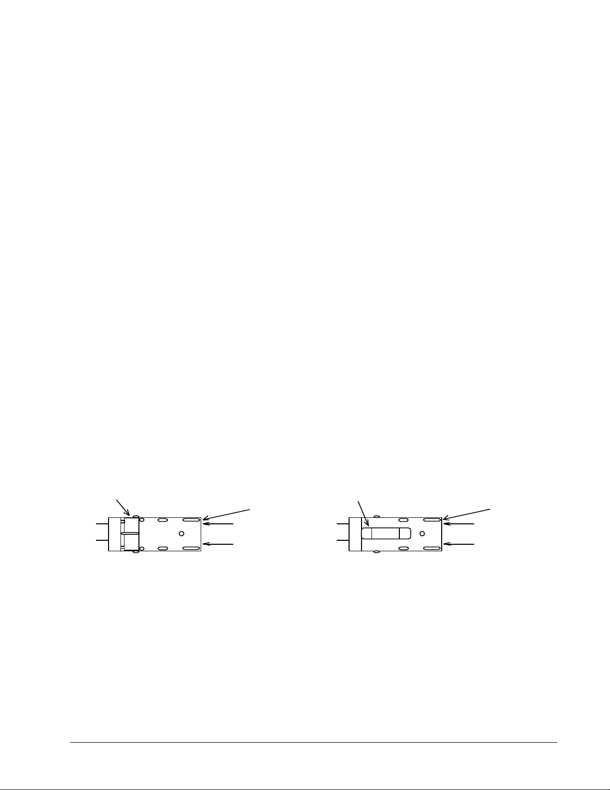
1.4.1 Main Fuse Configuration
Location of 115V Text
Location of 230V Text
Two 5 x 20MM Fuses One Each Side
The main fuse(s) on the LOKPRINT are located inside the AC power entry
receptacle. The entry has a fuse drawer that holds the fuse(s) and selects the
appropriate line voltage. If the number in the window DOES NOT match the AC
line intended to be supplied to the LOKPRINT, DO NOT plug the power cord in.
Reconfigure as follows:
1) Using a flat blade screwdriver, open the AC entry by lifting the tab just above the
voltage indicator window.
2) Remove the red fuse drawer.
3) Remove all fuses and the fuse jumper if it is present.
4) Insert into the fuse drawer the correct number and style of fuses and fuse jumper
for your application.
Configuration Number One: Line voltage between the range of
100 - 132 VAC @ 50 - 60Hz
1) Install one 921122 - 5.0A 250V TD 1/4 X 1 1/4 Fuse
2) Install one Fuse Jumper
See Figure FUSE1
Configuration Number Two: Line voltage between the range of
180 - 240VAC @ 50 - 60Hz
1) Install two 990688 - 2.5A 250V TD 5X20mm Fuses
NOTE: The fuse jumper must be removed to install both 5 x
The fuses must be between points A and B as shown not B and C.
See Figure FUSE2
FIGURE FUSE1
Fuse Jumper
One 1/4 x 1 1/4" Fuse Far Side
5) Reinsert the fuse drawer into the AC entry with the desired voltage up.
6) Close the AC entry and verify the correct voltage is now visible.
20mm fuses.
FIGURE FUSE2
5 x 20 mm fuse
FRONT FRONT
Location of 115V Text
Location of 230V Text
A
B
C
Users Manual LOKPRINT™ 1. Operation •••• 9
Page 10

1.4.2 Internal Fuse Configuration
FUSE 115VAC 230VAC
F1 4.0A 250V TD 990765 2.0A 250VAC TD 990759
F2 4.0A 250V TD 990765 2.0A 250VAC TD 990759
F3 1.0A 250V FA 990754 1.0A 250V FA 990754
F4 1.0A 250V FA 990754 1.0A 250V FA 990754
1.5 Heater Caution and Care
1.5.1 Caution
The heater platen is pre-set to a temperature of 410 deg. F (210 deg C), extra care
and caution should be taken when threading the machine while the heaters are on.
Any maintenance or cleaning should be done after the machine has been turned off
and allowed time for cool down.
1.5.2. Care
The heater platen should be kept clean and smooth for proper label sublimation. If
the heater develops a build up, it should be cleaned using alcohol and a clean dry
cloth. The heater surface is anodized aluminum and can be cleaned with cleaning
pads similar to those used for cleaning Teflon® pans. If the buildup is excessive, a
razor blade may be used to remove the residue. Use caution to prevent damage to the
surface of the platen.
NOTE: Cleaning should only be done with the heaters off and cooled.
10 •••• 1. Operation Users Manual LOKPRINT™
Page 11

2. Troubleshooting
2.1 Troubleshooting Mechanical
2.1.1 Tape Contact
If the tape fails to make proper contact with the heater platen, stop the printer. This
will save on unsublimated labels. Check to see if the flag sensor is adjusted properly
to signal when the rollers are in the lowest possible position.
2.1.2 Tape Release
The Tape Rollers should release and swing to the “up” position when there is a halt
in the printing sequence or if the power has been cut from either machine. If the
Tape Rollers fail to bring the tape to the highest possible position, check to see if the
Lift Spring is in position. The spring may wear with excessive use. Remove the tape
from the rollers and test by holding down the Tape rollers and letting them rise up
into position.
2.1.3 Feed Roller
The Feed Rollers have two springs that supply even tension for tracking. If the
tracking of the tape fails, check to see if one of the springs may have come
unattached, and reattach. The feed rollers are also equipped with a hand knob used
to thread the machine. This knob should turn freely with very little resistance. If
resistance occurs, check to see if the bearings need to be greased. Also check to see
that the timing belt tension is not excessive.
2.2 Troubleshooting Electrical
2.2.1 Defective Heater Elements
If the heater elements are suspect, due to improper heating, the probable cause is
that one of the heaters is burned out. The heater connections can be found on the
terminal block in the back of the cabinet. A multimeter can be used to test the
heaters. Each heater should read 300 ohms or lower (depending on model), a
discontinuity means that the heater is burned out. (Refer to the schematic for correct
connections)
2.2.2 Defective Thermocouple
The thermocouple wire is defective when the heaters are overheating and the digital
read-out on the FUJI Temperature Controller is reading room temperature.
Users Manual LOKPRINT™ 2. Troubleshooting •••• 11
Page 12

Electrical Schematics
12 •••• Electrical Schematics Users Manual LOKPRINT™
Page 13

115 / 230 Volt Schematic
Users Manual LOKPRINT™ Electrical Schematics •••• 13
Page 14

Optional Heater - 115 Volt Schematic
14 •••• Electrical Schematics Users Manual LOKPRINT™
Page 15

Optional Heater - 230 Volt Schematic
Users Manual LOKPRINT™ Electrical Schematics •••• 15
Page 16

Page 17

Mechanical Assembly Drawings
Users Manual LOKPRINT™ Mechanical Assembly Drawings •••• 17
Page 18

Cover Assembly
18 •••• Mechanical Assembly Drawings Users Manual LOKPRINT™
Page 19

Cover Parts List
Item Part # Description Qty
1 221021 Frame Brace Assembly 1
2 221002 Heat Deflector 1
3 221014 Feed Tray 1
4 221003 Front Cover 1
5 221017 Front Access Cover 1
6 221090 Assembly, Back Cover With Fan 1
7 421206 Knob 2
8 341210 Rubber Foot 5
9 224051 Hinge, Access Cover 2
10 990066 8-32 x ¼” Button Head Screw 3
11 990090 10-32 x 3/8” Button Head Screw 8
12 990029 6-32 x ¼” Flat Head Screw 2
13 990120 ¼-20 x ½” Cap Screw 4
14 990065 8-32 x 3/8” Button Head Screw 9
15 221119P Pyrometer 1
16 221120P Pyrometer 1
17 990019 6-32 x ¼” Button Head Screw 2
18 221013 Tie Bar 1
19 224079 Wire, Stripper 1
Users Manual LOKPRINT™ Mechanical Assembly Drawings •••• 19
Page 20

Air Filter Assembly
20 •••• Mechanical Assembly Drawings Users Manual LOKPRINT™
Page 21

Air Filter Parts List
Item Part # Description Qty
1 221004 Back Cover 1
2 221194 Fan Motor Harnessed 1
3 281105 Guard, Finger 1
4 989987 6-32 E-S Nut 4
5 221200 Filter Label 1
6 991133 Assembly, Filter Guard 1
7 990033 6-32 x 1 ½ Fill. Head Screw 4
8 221024 Filter, Lokprint 1
Users Manual LOKPRINT™ Mechanical Assembly Drawings •••• 21
Page 22

Heater Assembly
22 •••• Mechanical Assembly Drawings Users Manual LOKPRINT™
Page 23

Heater Parts List
Item Part # Description Qty
1 221008 Heater Block 1
2 221007 Heater Base 1
3 365030 Spacer 4
4 101103 Heat Element 4
5 990083 10-32 x ¾” Cap Screw 4
6 990067 #8 Washer 4
7 990108 10-32 x ½” Truss Head Screw 2
8 990196 10-32 x ½” Flat Head Screw 2
9 101102 Thermocouple 2
10 221002 Heat Deflector 1
11 191116 Insulated Bushing 4
Users Manual LOKPRINT™ Mechanical Assembly Drawings •••• 23
Page 24

Optional Heater Assembly
2
3
4
7
5
10
9
5
8
12
6
11
14
1
24 •••• Mechanical Assembly Drawings Users Manual LOKPRINT™
Page 25

Optional Heater Parts List
ITEM PART NO. Description QTY
1 991040 10-32 x 3/4 Cap screw (ss) 4
2*
3** 221129 Heat element 120v 250 Watt 1
4*** 221130 Heat element 120v 300 Watt 1
5 101102 Thermocouple 2
6 191116 Insulated bushing 1
7 221016 Heat deflector 1
8 221007 Heater base 1
9 365030 Spacer 4
10 221091 Heater block assy 1
11 990067 Washer, #8 SAE 4
12 990196 10-32 x 1/2 Flat head screw 2
13 990108 10-32 x 1/2 Truss head screw 2
14 990728 Washer, #10 Lock 4
101103 Heat element 120v 200 Watt
*Item 2 – Use Part No. 101104 for 240V Machine
**Item 3 – Use Part No. 221131 for 240V Machine
***Item 4 – Use Part No. 221132 for 240V Machine
1
Users Manual LOKPRINT™ Mechanical Assembly Drawings •••• 25
Page 26

Tape Feed Assembly
26 •••• Mechanical Assembly Drawings Users Manual LOKPRINT™
Page 27

Tape Feed Parts Lists
Item Part # Description Qty Item Part # Description Qty
1 221021 Frame, Brace Ass’y 1
2 990325 3/16” “E” Ring 1
3 143018 Pick-up Roller 1
4 224039 Roller Ass’y 3
5 990326 ¼” “E” Ring 3
6 224016 Shaft, Pick-up Roller 1
7 224014 Shaft, Fabric Lift Long 2
8 224012 Spacer, Front 3
9 224055 Pivot Bushing 1
10 224057 Collar Bushing Lock 1
11 990167 ¼” SAE Washer 1
12 224008 Stand-off Pivot 1
13 224062 Pin, Lever Pivot 1
14 224059 Driven Swing Arm Ass’y 1
15 991013 Nylon Washer 2
16 224009 Spacer Swing Arm Rear 2
17 224074 Bracket Swing Arm 1
18 224071 Bracket Sensor Flag 1
19 990081 10-32 x ½” Cap Screw 3
20 990144 #10 Washer 1
21 990104 10-32 ES Nut 1
22 990196 10-32 x ½” Flat Head Screw 1
23 224048 Fabric Lift Spring 1
24 990736 Female Terminal 1
25 990103 10-32 Hex Nut 1
26 224015 Shaft Fabric Lift Short 1
27 990146 ¼-20 Hex Nut 1
28 990145 ¼” Lock Washer 1
29 224027 Web Guard Plate 1
30 990056 8-32 x ½” Flat Head Screw 1
31 990069 8-32 Hex Nut 1
Users Manual LOKPRINT™ Mechanical Assembly Drawings •••• 27
Page 28

Feed Assembly
28 •••• Mechanical Assembly Drawings Users Manual LOKPRINT™
Page 29

Feed Parts List
Item Part # Description Qty
1 105023 Impression Adj. Knob 1
2 224078 Shaft, Turn Knob 1
3
4
5
6
7
8
9
990456 8-32 x ½” F. H. Screw 4
224032 Front Mount Plate Ass’y 1
224080 Front Pressure Arm Ass’y 1
990344 ¼ x ½” Shoulder Screw 2
991106 Spring Feed Pressure 2
224030 Feed Base Ass’y 1
224035 Feed Roller Ass’y 1
10 224036 Driven Roller Ass’y 1
11 990058 8-32 x ¼” Set Screw 1
12 224031 Rear Mount Plate 1
13 221023 Bracket, Feed Tray Plate 1
14 990019 6-32 x ¼” Button Head Screw 1
15 990057 8-32 x 1/8” Sk Hd Set Screw 1
16 224081 Rear Pressure Arm Ass’y 1
224090 Feed Ass’y (complete)
Users Manual LOKPRINT™ Mechanical Assembly Drawings •••• 29
Page 30

Drive Assembly
30 •••• Mechanical Assembly Drawings Users Manual LOKPRINT™
Page 31

Drive Parts List
Item Part # Description Qty
1 221021 Frame Brace Ass’y 1
2 990050 8-32 x ¼” Cap Screw 2
3 990890 Mechanical Relay 1
4 112004 Pulley 28T 1
5 991112 Pulley 14T 1
6 991113 Timing Belt 54T 1
7 365023 Power Entry Module 1
8 224069 Drive, Capstan 1
9 224068 Shaft, Idler Pulley 2
10 224073 Drive, Idler Pulley 2
11 990090 10-32 x 3/8” Button Head Screw 2
12 990262 ¼” Snap Ring 2
13 990469 .031” Nylon Washer 2
14 358024 Jam Sensor Bracket 1
15 371131 Jam Sensor Harnessed 1
16 989997 2-56 x 3/8” Cap Screw 1
17 224072 Bracket, Sensor Stop 1
18 990020 6-32 x 3/8” Button Head Screw 2
19 990066 8-32 x ¼” Button Head Screw 2
20 221089K Kit, Cable Drive, LKP 1
Users Manual LOKPRINT™ Mechanical Assembly Drawings •••• 31
Page 32

Electrical Components
32 •••• Mechanical Assembly Drawings Users Manual LOKPRINT™
Page 33

Electrical Components Parts List
Item Part # Description Qty
1 221021 Frame Base Ass’y 1
2 990050 8-32 x ¼” Cap Screw 4
3 990707 Solid State Relay 2
4 990667 Fuse Block 1
5 990006 4-40 x ¼” Cap Screw 2
6 990768 Terminal Block and Cover 1
7 990044 8-32 x ¾” Button Head Screw 2
8 221124 Rheostat, 25 OHM 1
9 351141 Stepper Motor 1
10 990081 10-32 x ½” Cap Screw 3
11 221113 Feed Motor 1
Users Manual LOKPRINT™ Mechanical Assembly Drawings •••• 33
Page 34

Rewind Assembly Components
34 •••• Mechanical Assembly Drawings Users Manual LOKPRINT™
Page 35

Rewind Parts List
Item Part # Description Qty Item Part # Description Qty
1 112009 Rewind Lock Knob 1
2 111006 Pressure Collar 1
3 111017 Pressure Collar Spring 1
4 990020 6-32 x 3/8” Button Head Screw 6
5 111031 Disc, 10” Rewind 2
6 111033 Hub, 3” Core Insert 2
7 990176 5/16-18 x ½” Set Screw 1
8 111005 Rewind Shaft 1
9 341210 Feet, 1½” Dia. 4
10 990121 ¼-20 x 5/8” Cap Screw 4
11 990122 ¼-20 x ¾” Cap Screw 3
12 111003 Dancer Arm 1
13 990263 5/16” Snap Ring 2
14 112038 Roller 1
15 111018 Rewind Base Plate 1
16 111001 Face Plate 1
17 111008 Micro Bracket 1
18 990183 5/16-18 Hex Nut 1
19 111015 Dancer Spring 1
20 990171 5/16-18 x 1” Cap Screw 1
21 990372 5/16” Collar 3
22 990094 10-32 x 3/16” Set Screw 4
23 111002 Torsion Collar 1
24 990085 10-23 x 1 ¼” Cap Screw 2
25 506005 Foil Drive Post 1
26 111009 Roller Chain 1
27 204049 25-20 x ½” Sprocket 1
28 921110 Micro Enclosure Cover 1
29 921131 Rewind Motor Micro Switch 1
30 990037 #6 Washer 2
31 990084 10-32 x 1” Cap Screw 2
32 990081 10-32 x ½” Cap Screw 2
33 111011 Rewind Motor Mount 1
34 990144 #10 Flat Washer 2
35 990120 ¼-20 x ½” Cap Screw 2
36 111016 25-15 x 5/16” Sprocket 1
37 111007 Rewind Motor 1
38 111013 Rewind Cover 1
39 990760
990761
110V Heat Switch
250V Heat Switch
40 990090 10-32 x 3/8” Button Head Screws 5
921136 Transformer (Not Shown) 1
110021 Lokprint Rewind 110V
110022 Lokprint Rewind 220V
1
Users Manual LOKPRINT™ Mechanical Assembly Drawings •••• 35
 Loading...