


IWH3216 Touch/Touch II
16CH Embedded Hybrid DVR
User’s Manual
May 2012

FCC NOTICE (Class A)
This device complies with Part 15 of the FCC Rules. Operation is subject to the following two conditions: (1) this device may not cause harmful interference, and (2) this device must accept any interference received, including interference that may cause undesired operation.
Federal Communications Commission Statement
NOTEThis equipment has been tested and found to comply with the limits for a Class A digital device, pursuant to Part 15 of the FCC Rules. These limits are designed to provide reasonable protection against harmful interference in a residential installation. This equipment generates uses and can radiate radio frequency energy and, if not installed and used in accordance with the instructions, may cause harmful interference to radio communications. However, there is no guarantee that interference will not occur in a particular installation. If this equipment does cause harmful interference to radio or television reception, which can be determined by tuning the equipment off and on, the user is encouraged to try to correct the interference by one or more of the following measures:
Reorient or relocate the receiving antenna.
Increase the separation between the equipment and receiver.
Connect the equipment into an outlet on a circuit different from that to which the receiver is connected. Consult the dealer or an experienced radio/television technician for help.
Class A ITE
Class A ITE is a category of all other ITE which satisfies the class A ITE limits but not the class B ITE limits. Such equipment should not be restricted in its sale but the following warning shall be included in the instructions for use: Warning ─This is a class A product. In a domestic environment this product may cause radio interference in which case the user may be required to take adequate measures.
European Community Compliance Statement (Class A)
This product is herewith confirmed to comply with the requirements set out in the Council Directives on the Approximation of the laws of the Member States relating to Electromagnetic Compatibility Directive 2004/108/EC.
Warning - This is a Class A product. In a domestic environment this product may cause radio interference in which case the user may be required to take adequate measures to correct this interference.
DISCLAIMER
No warranty or representation, either expressed or implied, is made with respect to the contents of this documentation, its quality, performance, merchantability, or fitness for a particular purpose. Information presented in this documentation has been carefully checked for reliability; however, no responsibility is assumed for inaccuracies. The information contained in this documentation is subject to change without notice.
In no event will AVer Information Inc. be liable for direct, indirect, special, incidental, or consequential damages arising out of the use or inability to use this product or documentation, even if advised of the possibility of such damages.
TRADEMARKS
“AVer” is a trademark owned by AVer Information Inc. Other trademarks used herein for description purpose only belong to each of their companies.
COPYRIGHT
© 2012 AVer Information Inc. All rights reserved.
No part of this document may be reproduced or transmitted in any form, or by any means without the prior written permission of AVer Information Inc. AVer Information Inc. reserves the rights to modify its models, including their characteristics, specifications, accessories and any other information stated herein without notice. The official printout of any information shall prevail should there be any discrepancy between the information contained herein and the information contained in that printout.
The mark of Crossed-out wheeled bin indicates that this product must not be disposed of with your other household waste. Instead, you need to dispose of the waste equipment by handing it over to a designated collection point for the recycling of waste electrical and electronic equipment. For more information about where to drop off your waste equipment for recycling, please contact your household waste disposal service or the shop where you purchased the product.

WARNING
-TO REDUCE RISK OF FIRE OR ELECTRIC SHOCK, DO NOT EXPOSE THIS APPLIANCE TO RAIN OR MOISTURE.
-GUARANTEE BECOMES VOID IN CASE OF ANY UNAUTHORIZED MODIFICATIONS INTO DOM CONTENTS.
-DO NOT REMOVE REMOVABLE HDD TRAY SHILE SYSTEM IN USE. IT WOULD DAMAGE DOM CONTENTS.
-DO NOT INSTALL DVR IN THE AIRTIGHT ENVIROEMENT. IT WOULD CAUSE INSTABILITY OF THE SYSTEM.
CAUTION
IF THERE IS ANY DAMAGE, SHORTAGE OR INAPPROPRIATE ITEM IN THE PACKAGE, PLEASE CONTACT WITH YOUR LOCAL DEALER. WARRANTY VOID FOR ANY UNAUTHORIZED PRODUCT MODIFICATION.
Manual Conventions
The following conventions are used throughout this manual
Caution symbol is intended to alert the user of the important installation and operating instructions. Fail to comply may damage the system.
i |
Information symbol is intended to provide additional information for the purpose of clarification. |
|
|
TABLE OF CONTENTS
Chapter 1 |
Introduction .................................................................................... |
1 |
||
1.1 |
Package Contents.................................................................................................................... |
1 |
||
|
1.1.1 |
IWH3216 Touch............................................................................................................. |
1 |
|
|
1.1.2 |
IWH3216 Touch II.......................................................................................................... |
1 |
|
|
1.1.3 |
Optional Accessories..................................................................................................... |
1 |
|
1.2 |
Specification |
............................................................................................................................. |
2 |
|
1.3 |
Hardware Introduction.............................................................................................................. |
4 |
||
|
1.3.1 |
Front ....................................................................................................................Panel |
4 |
|
|
1.3.1.1 ................................................................................................... |
IWH3216 Touch |
4 |
|
|
1.3.1.2 ................................................................................................ |
IWH3216 Touch II |
6 |
|
|
1.3.2 |
Back Panel .................................................................................................................... |
7 |
|
|
1.3.2.1 ................................................................................................... |
IWH3216 Touch |
7 |
|
|
1.3.2.2 ................................................................................................ |
IWH3216 Touch II |
8 |
|
Chapter 2 ..................................................................... |
Hardware Installation |
9 |
||
2.1 |
Hard Disk Installation ............................................................................................................... |
9 |
||
|
2.1.1 |
IWH3216 .............................................................................................................Touch |
9 |
|
|
2.1.2 |
IWH3216 .........................................................................................................Touch II |
11 |
|
2.2 |
Connecting Device................................................................................................................. |
12 |
||
|
2.2.1 |
RS485 ...............................................................................................Cable Definition |
12 |
|
|
2.2.2 |
IWH3216 ...........................................................................................................Touch |
12 |
|
|
2.2.3 |
IWH3216 ........................................................................................................Touch II |
13 |
|
2.3 |
Pin Definition ............................................................................of Sensor/Relay/RS485 Port |
14 |
||
|
2.3.1 Pin definition ..............................................................................of Sensor and Relay |
14 |
||
|
2.3.2 Pin Definition ........................................................................................of RS485 Port |
15 |
||
Chapter 3 .............................................................. |
Using the DVR Software |
16 |
||
3.1 |
Running the ........................................................................................Unit for the First Time |
16 |
||
3.2 |
Familiarizing ............................................................the Buttons in Advanced/Preview Mode |
16 |
||
|
3.2.1 Using ..............................................................................................Event Log Viewer |
20 |
||
|
3.2.1.1 .............................................................................................. |
Using POSViewer |
21 |
|
|
3.2.1.2 ............................................................................... |
Using Counting Log Viewer |
22 |
|
|
3.2.1.3 .................................................................................... |
Using the Object Viewer |
23 |
|
3.3 |
Familiarizing ...........................................................................the Buttons in Playback Mode |
24 |
||
|
3.3.1 To Cut ......................................and Save the Wanted Portion of the Recorded Video |
28 |
||
|
3.3.2 To Bookmark ...........................................................................a Section of the Video |
29 |
||
|
3.3.3 To Search .............................................................................Using the Visual Search |
30 |
||
|
3.3.4 To Search .............................................................................Using the Event Search |
31 |
||
|
3.3.5 To Search .......................................................................Using the Intelligent Search |
32 |
||
3.4 |
Familiarizing ...........................................................................the Buttons in Compact Mode |
33 |
||
3.5 |
Function Buttons ..........................................................................in PTZ Camera Controller |
34 |
||
3.6 |
Setting Up and .............................................................................................Using the Emap |
35 |
||
|
3.6.1 To Set ....................................................................................................Up the Emap |
35 |
||
|
3.6.2 To Use .........................................................................................................the Emap |
36 |
||
3.7 |
To Setup the PTZ/IP PTZ Camera ......................................................................................... |
37 |
||
|
3.7.1 |
Setup the PTZ Camera ............................................................................................... |
37 |
|
|
3.7.2 |
Setup the IP PTZ Camera ........................................................................................... |
39 |
|
Chapter 4 |
Customizing the DVR System ..................................................... |
41 |
||
4.1 |
System Setting....................................................................................................................... |
41 |
||
|
4.1.1 |
To Set the POS Setting ............................................................................................... |
53 |
|
|
4.1.1.1 |
General Setting ................................................................................................. |
53 |
|
|
4.1.1.2 |
Advanced Setting .............................................................................................. |
59 |
|
|
4.1.1.3 |
POS Database Setting ...................................................................................... |
60 |
|
4.2 |
Camera Setting ...................................................................................................................... |
61 |
||
|
4.2.1 |
Setup the Object Counting .......................................................................................... |
66 |
|
|
4.2.2 |
To Setup the FaceFinder ............................................................................................. |
68 |
|
|
4.2.3 |
Setup PTZ Tracking..................................................................................................... |
70 |
|
|
4.2.4 |
Create a Camera Group.............................................................................................. |
72 |
|
4.3 |
Recording Setting .................................................................................................................. |
74 |
||
|
4.3.1 |
Analog Camera ........................................................................................................... |
74 |
|
|
4.3.2 |
IP Camera ................................................................................................................... |
78 |
|
|
4.3.3 |
To Mask/Shield an area on the screen ........................................................................ |
80 |
|
4.4 |
Network Setting...................................................................................................................... |
81 |
||
4.5 |
Schedule Setting.................................................................................................................... |
84 |
||
4.6 |
Backup Setting....................................................................................................................... |
86 |
||
|
4.6.1 |
To Backup file.............................................................................................................. |
86 |
|
|
4.6.2 |
Setup Quick Backup.................................................................................................... |
87 |
|
4.7 |
Sensor Setting ....................................................................................................................... |
88 |
||
|
4.7.1 |
To Setup External I/O Box ........................................................................................... |
89 |
|
4.8 |
Relay Setting.......................................................................................................................... |
90 |
||
4.9 |
Alarm Setting ......................................................................................................................... |
91 |
||
|
4.9.1 |
To Setup Alarm Relay:................................................................................................. |
97 |
|
|
4.9.2 |
To Setup the Alarm Sound Setting: ............................................................................. |
98 |
|
|
4.9.3 |
To Setup Send E-mail Setting: .................................................................................... |
98 |
|
|
4.9.4 |
To Setup FTP Setting: ................................................................................................. |
99 |
|
|
4.9.5 |
To Setup Alarm Recording Setting: ........................................................................... |
100 |
|
|
4.9.6 |
To Setup SMS/MMS Setting:..................................................................................... |
100 |
|
|
4.9.7 |
To Setup PTZ Preset Point:....................................................................................... |
101 |
|
|
4.9.8 |
To Setup Alarm SOP: ................................................................................................ |
101 |
|
|
4.9.9 |
To Setup CMS Setting ............................................................................................... |
102 |
|
|
4.9.10 To Setup POS Keyword Setting ................................................................................ |
102 |
||
|
4.9.11 Missing, Suspicious Object, and Scene Change Detected........................................ |
103 |
||
4.10 |
User Setting |
......................................................................................................................... |
105 |
|
Chapter 5 ................................................................ |
Backup Video Players |
107 |
||
5.1 |
Familiarizing ....................................................................................the Buttons in QPlayer |
107 |
||
Chapter 6 ..................................................... |
Using the Remote Programs |
110 |
||
6.1 |
Familiarizing ..................................................................................the Buttons in PCViewer |
111 |
||
|
6.1.1 |
PCViewer .......................................................................................................Screen |
111 |
|
|
6.1.2 PCViewer Control Panel............................................................................................. |
112 |
|
|
6.1.3 To Setup Remote System Setting .............................................................................. |
114 |
|
|
6.1.3.1 |
Basic Setting ................................................................................................... |
114 |
|
6.1.3.2 |
Advance Setting .............................................................................................. |
116 |
6.2 |
Familiarizing the Buttons in Remote Console ...................................................................... |
133 |
|
|
6.2.1 To Setup Remote Console Setting ............................................................................ |
134 |
|
|
6.2.2 Familiarizing the Buttons in PTZ Camera Controller ................................................. |
135 |
|
6.3 |
Using the Remote Playback................................................................................................. |
136 |
|
|
6.3.1 Familiarizing the Buttons in Local Playback Mode .................................................... |
137 |
|
|
6.3.2 Familiarizing the Buttons in RealTime Playback Mode.............................................. |
140 |
|
|
6.3.3 Familiarizing the Buttons in Download and Playback Mode ...................................... |
142 |
|
6.4 |
Using Mobile Device to Access DVR server......................................................................... |
144 |
|
6.5 |
Using PDAViewer to Access DVR Server ............................................................................ |
144 |
|
|
6.5.1 To install PDAViewer thru ActiveSync........................................................................ |
144 |
|
|
6.5.2 To install PDAViewer from the Internet ...................................................................... |
145 |
|
|
6.5.3 To Use the PDAViewer .............................................................................................. |
146 |
|
|
6.5.4 To Playback in PDAViewer ........................................................................................ |
148 |
|
|
6.5.5 Using JavaViewer to Access DVR Server ................................................................. |
149 |
|
|
6.5.6 To Use the Java-Viewer ............................................................................................ |
149 |
|
Chapter 7 |
iEnhance ..................................................................................... |
151 |
|
7.1 |
To Use iStable ...................................................................................................................... |
152 |
|
Chapter 8 |
Web Tools ................................................................................... |
154 |
|
8.1 |
Remote Setup ...................................................................................................................... |
154 |
|
|
8.1.1 To Add DVR server.................................................................................................... |
154 |
|
|
8.1.2 To Setup Remote DVR Server .................................................................................. |
156 |
|
8.2 |
Remote Backup ................................................................................................................... |
157 |
|
Appendix A Registering Domain Names....................................................... |
161 |
||
Appendix B |
Network Service Port ............................................................... |
162 |
|
Appendix C |
Using Recovery CD to Recovery System ............................... |
163 |
|
Appendix D |
Pin Definition of Audio In Port................................................. |
167 |
|
Appendix E |
USB Recovery........................................................................... |
168 |
|

Chapter 1 |
Introduction |
1.1Package Contents
1.1.1IWH3216 Touch
IWH3216 Touch unit |
Power Cord (*The power cord may vary according to the |
Optical USB mouse |
local electricity system.) |
Software CD (Manual and Quick Guide are included) |
Power Adaptor |
Recovery CD |
Audio in cable(2 Spot monitor cables are included) |
SATA cable for hard disk installation |
Video in cable(16channels) |
|
RS-485 cable |
1.1.2IWH3216 Touch II
IWH3216 Touch II unit |
Power Cord (*The power cord may vary according to the |
Optical USB mouse |
local electricity system.) |
Software CD (Manual and Quick Guide are included) |
Power Adaptor |
SATA cable for hard disk installation |
Audio in cable(2 Spot monitor cables are included) |
RS-485 cable
i- If there is any damage, shortage or inappropriate item in the package contents, please contact with local dealer.
-Rack ears are not included.
1.1.3Optional Accessories
Loop through cable(16channels)
Rack ears
Remote controller
IR Extended Cable
1

1.2Specification
IWH3216 Touch |
IWH3216 Touch II |
Model |
XB-31A01 |
|
XB-31A02 |
XB-51A01 |
|
XB-51A02 |
|
|
|
|
|
|
|||
Compression |
H/W compression |
H/W compression |
|||||
|
|
|
|
|
|
|
|
Video format |
|
H.264 |
|
H.264 |
|||
|
|
|
|
|
|
|
|
Video input |
|
16 |
|
16 |
|||
|
|
|
|
|
|
|
|
IP cam support |
|
16 |
|
16 |
|||
|
|
|
|
|
|
|
|
Total MegaPixel |
|
42M |
|
42M |
|||
resolution of IP cam |
|
|
|||||
|
|
|
|
|
|
||
|
|
|
|
|
|
|
|
Loop out |
|
16(optional) |
|
16 |
|||
|
|
|
|
|
|||
VGA output |
Dual-output, support VGA interface |
Dual-output, support VGA interface |
|||||
VGA1: 1920*1200, VGA2: 1280*1024 |
VGA1: 1920*1200, VGA2: 1280*1024 |
||||||
|
|||||||
|
|
|
|
|
|
|
|
Recording frame |
480/400 fps (NTSC/PAL) |
480/400 fps (NTSC/PAL) |
|||||
rate(CIF) |
|||||||
|
|
|
|
|
|
||
|
|
|
|
|
|
|
|
Recording frame |
240/200 fps (NTSC/PAL) |
240/200 fps (NTSC/PAL) |
|||||
rate(D1) |
|||||||
|
|
|
|
|
|
||
|
|
|
|
|
|
|
|
Audio input |
|
16 |
|
16 |
|||
|
|
|
|
|
|
|
|
Sensor in/ Relay out |
|
16/4 |
|
16/4 |
|||
|
|
|
|
|
|||
SPOT out |
2, 1ch and analog output only |
2, 1ch and analog output only |
|||||
|
|
|
|
|
|
|
|
Removable HDD Tray |
N/A |
|
1 |
3 |
|
4 |
|
|
|
|
|
|
|
|
|
DVD-RW |
Yes |
|
N/A |
Yes |
|
N/A |
|
|
|
|
|
|
|
|
|
HDD support |
3 |
|
4 |
3 |
|
4 |
|
|
|
|
|
|
|
|
|
e-SATA port |
|
1 |
|
1 |
|||
|
|
|
|
|
|||
Accessory Included |
|
mouse |
|
mouse |
|||
|
|
|
|||||
Ethernet port |
2, RJ-45 interface |
2, RJ-45 interface |
|||||
|
|
|
|||||
Ethernet bandwidth |
10/100/1000 Mbps |
10/100/1000 Mbps |
|||||
|
|
|
|
|
|||
RS232 port |
|
1 |
|
1 |
|||
|
|
|
|
|
|||
RS485 port |
|
1 |
|
1 |
|||
|
|
|
|||||
USB2.0 port |
Front 2 ports, Rear 4 ports |
Front 2 ports, Rear 4 ports |
|||||
|
|
|
|
|
|||
LCD display |
|
N/A |
Temperature/ System status/ HDD left size/ |
||||
|
|
Alarm status |
|||||
|
|
|
|
|
|||
|
|
|
|||||
Operation via front |
PTZ control/ channel select/ split select/ |
channel select/ split select/ playback control/ |
|||||
panel |
playback control/ mode select |
|
mode select |
||||
|
|
|
|
|
|
|
|
Transcode IP cam |
|
N/A |
|
N/A |
|||
video before saving |
|
|
|||||
|
|
|
|
|
|
||
Dimensions (W x H x D) |
430x65x370 mm |
430x110x420 mm |
|||||
|
|
|
|
|
|
||
|
|
2 |
|
|
|
||

IWH3216 Touch |
IWH3216 Touch II |
Model |
XB-31A01 |
XB-31A02 |
XB-51A01 |
XB-51A02 |
|
|
|
|
|
Power Supply |
|
120 Watt |
|
120 Watt |
|
|
|
||
Optional Accessory |
Loop through cable, RACK ears, Remote |
RACK ears, Remote Control, IR extended |
||
Control, IR extended cable |
|
cable |
||
|
|
|||
3
1.3Hardware Introduction
1.3.1Front Panel
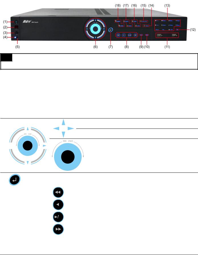
1.3.1.1IWH3216 Touch
TIP
Touch the blue word, button center, blue arrow, and blue area to make a selection or functional.
|
Name |
|
Function |
|
|
|
|
|
|||
|
|
|
|
|
|
(1) |
Power |
|
ON/OFF DVR unit |
|
|
|
|
|
|
|
|
(2) |
IR Sensor |
|
Receive signal from the remote control to operate the DVR unit |
|
|
|
|
|
|
|
|
(3) |
IR Sensor port |
|
For extended IR sensor cable(optional) |
|
|
|
|
|
|
|
|
(4) |
System power indicator |
|
System power status indicators. Indicate running state of system. Lights when the |
|
|
|
system is running. |
|
|||
|
|
|
|
|
|
|
|
|
|
|
|
(5) |
HDD indicator |
|
When DVR system is recording, the light will keep flashing. |
|
|
Move cursor to left, right, up, and down direction DVR application interface and function setup window.
To move PTZ camera lens to left, right, up and down in PTZ mode
(6) 
Touch the blue area to go to next or previous frame.
Go forward direction is Next frame and backward direction is
Previous frame.
(7) |
|
Confirm or make a selection |
|||
|
|
|
|
|
|
|
|
|
|
|
To playback video at slower speed of 1/2x, 1/4x, 1/6x, 1/8x, 1/16x, or 1/32x. |
|
|
|
|
|
|
|
|
|
|
|
To rewind the recorded video |
(8) |
Playback Control |
|
|
|
|
|
buttons |
|
|
|
To pause playback |
|
|
|
|
|
To start playback |
|
|
|
|
|
|
|
|
|
|
|
To playback video at faster speed of 2x, 4x, 6x, 8x, 16x, or 32x. |
|
|
|
|||
|
|
Switch between preview, playback, and EMap mode. |
|||
(9) |
Mode |
In preview mode, user can switch between Preview, Playback and EMap mode. |
|||
In playback mode, user can switch between Preview and Playback mode. In EMap mode, user can switch between Preview and Emap mode.
4
|
Name |
|
|
Function |
|
|
|
|
|
||
|
|
|
|
|
|
|
|
||||
|
|
|
|
|
|
|
|
|
|
||
|
(10) Menu |
|
|
Call out system setup menu on preview mode |
|
|
|||||
|
|
|
|
|
|
|
|
|
|
|
|
|
|
|
Call out playback menu on playback mode |
|
|
||||||
|
|
|
|
|
|
||||||
|
|
|
|
|
|
|
|
|
|||
|
(11) USB 2.0 port |
|
|
2 x USB 2.0 ports for connecting USB device, ex: USB pen drive, external hard disk, |
|
||||||
|
|
|
mouse…and so on. |
|
|
|
|
||||
|
|
|
|
|
|
|
|
||||
|
|
|
|
|
|
|
|||||
|
|
|
|
A functional key for multiple system control. Press |
to enable FN modes (The |
|
|||||
|
|
|
|
word “FN” will show up in the left bottom corner on screen). To exit FN modes, press |
|
||||||
|
|
|
|
again. |
|
|
|
|
|
||
|
|
+ |
|
|
: Switch to single screen display mode |
|
|
||||
|
|
+ |
|
|
: Switch to QUAD display mode |
|
|
||||
|
|
|
|
|
|
||||||
|
|
|
|
|
|
||||||
|
|
+ |
|
|
: Switch to 9 spilt screen display mode |
|
|
||||
(12) |
+ |
|
|
: Switch to 16 split screen display mode |
|
|
|||||
|
|
|
|
||||||||
|
|
+ |
|
|
: Switch to one single and 7 + 1 spilt screen display mode |
|
|||||
|
|
+ |
|
|
: Switch to one single and 12+ 1 spilt screen display mode |
|
|||||
|
|
+ |
|
|
: Enable/disable channel auto switch cycle |
|
|||||
|
|
+ |
|
|
: Switch to full screen display mode. Press again to back to original |
|
|||||
|
|
|
|
display mode. |
|
|
|
|
|
||
|
|
|
|
|
|
|
|
|
|
||
|
|
|
|
|
|
|
- |
Channel camera selection number in playback and |
|
||
|
|
|
|
|
|
|
|
preview mode. For the channel over 10, press |
|
||
|
|
|
|
|
|
|
|
|
, then press |
~ |
|
|
(13) Number buttons |
~ |
- |
Press |
button can switch to different screen display |
|
|||||
|
|
|
|
|
|
|
|
modes ( |
~ |
). |
|
-Press 


 and number button (


 ~
~ 

 ), to set the preset position in the PTZ mode.
(14) |
|
|
|
Adjust the PTZ lens to the position that user wants. And then, press |
with |
|||||||
|
|
|
number button to setup the PTZ camera preset position. |
|
|
|||||||
|
|
|
|
|
|
|||||||
|
|
|
|
|
|
|
|
|
|
|
||
|
|
Operate the PTZ cameras automatically based on the selected camera group preset |
||||||||||
|
|
position number. |
|
|
||||||||
(15) |
|
|
|
|
|
|
|
|
|
|
|
|
|
|
|
i |
Without setup preset position, the preset button ( |
) will not be |
|||||||
|
|
|
|
|||||||||
|
|
|
|
|
|
functional when press it. To setup preset position, please refer to Chapter 3.7. |
||||||
|
|
|
|
|
|
|
|
|
|
|
|
|
|
|
|
|
|
|
|
|
|
|
|
|
|
|
|
|
|
|
|
|
|
|
|
To speed up movement of PTZ camera lens |
|
|
(16) |
Speed + / Speed - |
|
|
|
|
|
|
|
||||
|
|
|
|
|
|
|
|
|
|
To speed down movement of PTZ camera lens |
|
|
|
|
|
|
|
|
|
|
|
|
|||
|
|
|
|
|
|
|
|
|
|
|
|
|
|
|
|
|
|
|
|
|
|
|
To focus in PTZ camera lens |
|
|
(17) |
Focus + / Focus - |
|
|
|
|
|
|
|
||||
|
|
|
|
|
|
|
|
|
|
To focus out PTZ camera lens |
|
|
|
|
|
|
|
|
|
|
|
|
|
||
|
|
|
|
|
|
|
|
|
|
|
|
|
|
|
|
|
|
|
|
|
|
|
To zoom in view of PTZ camera lens |
|
|
(18) |
Zoom + / Zoom - |
|
|
|
|
|
|
|
||||
|
|
|
|
|
|
|
|
|
|
To zoom out view of PTZ camera lens |
|
|
|
|
|
|
|
|
|
|
|
|
|
||
|
|
|
|
|
|
|
|
|
|
|
|
|
|
|
|
|
|
|
|
|
|
|
|
|
|
5
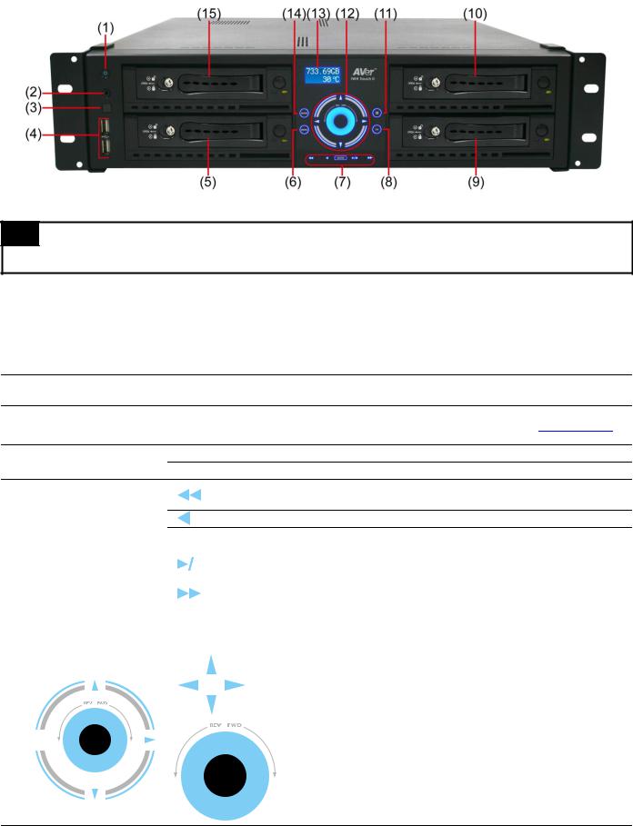
1.3.1.2IWH3216 Touch II
TIP
Touch the blue word, button center, blue arrow, and blue area to make a selection or functional.
|
Name |
|
Function |
|
|
|
|
|
|||
|
|
|
|
|
|
(1) |
Power |
|
ON/OFF DVR unit |
|
|
|
|
|
|
|
|
(2) |
IR Sensor |
|
Receive signal from the remote control to operate the DVR unit |
|
|
|
|
|
|
|
|
(3) |
IR Sensor port |
|
For extended IR sensor cable(optional) |
|
|
(4) USB port
(5)&(9)&(10)&(15) Removable HDD drawer
(6) Menu
2 x USB 2.0 ports for connecting USB device, ex: USB pen drive, external hard disk, mouse…and so on.
Each HDD drawer can be installed one(1) SATA hard disk(see also Chapter 2.1.2)
Call out system setup menu on preview mode
Call out playback menu on playback mode
To playback video at slower speed of 1/2x, 1/4x, 1/6x, 1/8x, 1/16x, or 1/32x.
To rewind the recorded video
(7) Playback Control buttons |
Enter Confirm or make a selection |
|||||||
|
|
|
|
|
To pause playback |
|||
|
|
|
|
|
|
|||
|
|
|
|
|
|
|
|
|
|
|
|
|
|
|
To start playback |
||
|
|
|
|
|
|
|||
|
|
|
|
|
|
|
|
|
|
|
|
|
|
|
To playback video at faster speed of 2x, 4x, 6x, 8x, 16x, or 32x. |
||
(8) CH |
Press the button can select channel 1, 2, 3, 4, 5… to channel 16. |
|||||||
|
|
|
||||||
(11) Split screen mode |
Press the button can select single, QUAD, 9-split screen, 16-split screen, 7+1 split |
|||||||
screen, and 12+1 split screen mode. |
||||||||
|
||||||||
|
|
|
|
|
|
|
|
|
|
|
|
|
|
|
|
Move cursor to left, right, up, and down direction DVR application |
|
|
|
|
|
|
|
|
interface and function setup window. |
|
|
|
|
|
|
|
|
|
|
|
|
|
|
|
|
|
To move PTZ camera lens to left, right, up and down in PTZ mode |
|
|
|
|
|
|
|
|
|
|
(12) 
Touch the blue area to go to next or previous frame.
Go forward direction is Next frame and backward direction is
Previous frame.
(13) LED display panel |
Display current hard disk free space and system temperature. |
|
|
6

|
Name |
|
Function |
|
|
|
|
||
|
|
|
|
|
|
|
|
Switch between preview, playback, and EMap mode. |
|
|
|
|
In preview mode, user can switch between Preview, Playback and EMap |
|
|
(14) Mode |
|
mode. |
|
|
|
|
In playback mode, user can switch between Preview and Playback mode. |
|
|
|
|
In EMap mode, user can switch between Preview and Emap mode. |
|
1.3.2Back Panel
1.3.2.1IWH3216 Touch
|
Name |
|
Function |
|
|
|
|
|
|||
(1) |
Video Loop Out(16CH) |
|
Output the video signal to a CCTV monitor. |
||
|
|
|
|
||
(2) |
Video In |
|
Input the video camera signal and display it on channel 1~ 16. |
||
|
|
|
|
||
|
(3) Audio In & Spot Monitor |
|
Input the audio signal to audio input device (16 channels) and two(2) spot monitor |
||
|
|
|
|
output can display video on the Spot monitor when receive an alarm video. |
|
|
i |
The audio input device has its own power supply is necessary. |
|||
|
|
|
|
||
|
|
|
|
||
(4) |
Relay Out |
|
Support 4 relay devices (Relay: 1A @ 125V AC/30V DC). |
||
|
|
|
|
||
(5) |
Sensor In |
|
Support up to 16 sensor devices. |
||
|
|
|
|
||
(6) |
MIC In |
|
To connect the microphone. |
||
|
|
|
|
||
(7) |
USB port |
|
For connecting USB interface devices such pen drive, external USB hard disk, mouse, |
||
|
|
|
|
keyboard…etc. |
|
|
|
|
|
||
|
(8) eSATA interface |
|
For connecting with e-SATA storage. |
||
|
|
|
|
||
(9) |
VGA Out 1/VGA Out 2 |
|
Output the video signal to LCD monitor(dual monitor) |
||
|
|
|
|
||
|
(10) RS485 |
|
For PTZ camera (see Appendix E) or System Controller Pro connection. |
||
|
|
|
|
||
|
(11) Power Plug |
|
Connect the power cord into this port. |
||
|
|
|
|
||
|
(12) RS232 port |
|
For POS device connection. |
||
|
|
|
|
||
|
(13) LAN 1/ LAN 2 Port |
|
For Gigabit Ethernet connection. |
||
|
|
|
|
||
|
(14) Audio output |
|
For audio output device connection, such as speaker. |
||
|
|
|
|
|
|
7

1.3.2.2IWH3216 Touch II
|
Name |
|
Function |
|
|
|
|
|
|||
(1) |
Video Loop Out(16CH) |
|
Output the video signal to a CCTV monitor. |
||
|
|
|
|
||
(2) |
Video In |
|
Input the video camera signal and display it on channel 1~ 16. |
||
|
|
|
|
||
|
(3) Audio In & Spot Monitor |
|
Inputs the audio signal to audio input device (16 channels) and two(2) spot monitor |
||
|
|
|
|
output can display video on the Spot monitor when receive an alarm video. |
|
|
i |
The audio input device has its own power supply is necessary. |
|||
|
|
|
|
||
|
|
|
|
||
(4) |
Relay Out |
|
Support 4 relay devices (Relay: 1A @ 125V AC/30V DC). |
||
|
|
|
|
||
(5) |
Sensor In |
|
Support up to 16 sensor devices. |
||
|
|
|
|
||
|
(6) Audio output |
|
For audio output device connection, such as speaker. |
||
|
|
|
|
||
(7) |
MIC In |
|
To connect the microphone. |
||
|
|
|
|
||
(8) |
USB port |
|
For connecting USB interface devices such pen drive, external hard disk, mouse, |
||
|
|
|
|
keyboard…etc. |
|
|
|
|
|
||
(9) |
LAN 1/ LAN 2 Port |
|
For Gigabit Ethernet connection. |
||
|
|
|
|
||
|
(10) eSATA interface |
|
For connecting with e-SATA storage. |
||
|
|
|
|
||
|
(11) VGA Out 1/VGA Out 2 |
|
Output the video signal to LCD monitor(dual monitor) |
||
|
|
|
|
||
|
(12) RS485 |
|
For PTZ camera (see Appendix E) or System Controller Pro connection. |
||
|
|
|
|
||
|
(13) RS232 port |
|
For POS device connection. |
||
|
|
|
|
||
|
(14) Power Plug |
|
Connect the power cord into this port. |
||
|
|
|
|
|
|
8

Chapter 2 Hardware Installation
2.1Hard Disk Installation
2.1.1IWH3216 Touch
The DVR unit can support up to 3 hard disks. The hard disk installation step for IWH3216 Touch is same.Follow the illustrated instructions below to install the hard disk:
1.Loosen all screws (2 sides and back) and push the cover backward and lift to open the case cover.
2.Loosen the screws of holder to make hard disk install more easily.
3. Loosen all the screws of hard disk plate.
4.The hard disk plate can be installed 3 hard disks. User can choose the position and place the hard disk on it.
5. Turn the plate and hard disk over carefully and |
6. Screw the plate within hard disk inside the DVR unit. |
secure the hard disk on the plate. If hard disk cannot |
|
be fit to the screw hole, then, you may adjust the |
|
hard disk position to fit the screw hole. |
|
i - |
User can un-plug the SATA cable of the left side |
|
HDD for screwing plate inside the DVR more |
|
easily later. |
- |
User may manage all power cables and SATA |
|
cables for better connection. |
9
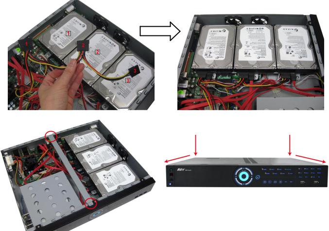
7. Plug the power cables and SATA cables into all three hard disk.
8. Screw the holder. |
9. Push the cover forward and secure the cover. |
10. User may now connect all the cables and power on the DVR unit.
10
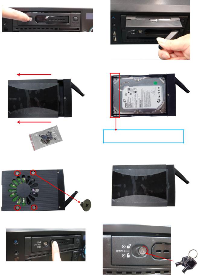
2.1.2IWH3216 Touch II
The DVR unit can support up to 4 SATA hard disks. Follow the illustrated instructions below to install the hard disk:
1. Push the lock to open the HDD drawer. |
2. And then, pull out the HDD drawer from DVR unit. |
3.Open the HDD drawer case cover and takes out the accessories kit (key & screws).
5.Turn the plate and hard disk over carefully and secure the hard disk inside the HDD drawer. Use the screw has flat head.
4.And then, place the SATA hard disk inside the HDD drawer.
The hard disk’s connect interface should be placed in this side of HDD drawer.
6.After screwed hard disk, turn the HDD drawer over and close the case cover.
7. Slide the HDD drawer back to the DVR unit.
8.Lock the HDD drawer by using the key that is included in accessories kit.
9. User may now connect all the cables and power on the DVR unit.
11
2.2Connecting Device
2.2.1RS485 Cable Definition
The following list is cable definition of the RS485 cable.
RS485 cable figure
|
RS485 cable site |
PTZ camera site |
|
|
|
|
(Color of cable) |
|
|
|
|
4 |
Red |
RX+ |
|
|
|
5 |
Green |
RX- |
|
|
|
8 |
White |
TX+ |
|
|
|
9 |
Black |
TX- |
|
|
|
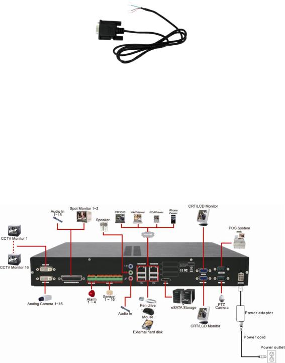
2.2.2IWH3216 Touch
The back panel of the DVR unit, user can connect up to 16 cameras of analog camera. The DVR unit also can connect 16 sensor devices, 4 alarm devices, and output video to 2 CRT/LCD monitor. Follow the illustration below to make the connection:
12
For backup recorded video, plugging the pen drive or external hard disk through USB port, and then, use the bundled software enables user to playback and export video clip.
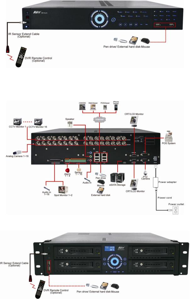
2.2.3IWH3216 Touch II
The back panel of the DVR unit, user can connect up to 16 cameras of analog camera. The DVR unit also can connect 16 sensor devices, 4 alarm devices, and output video to 2 CRT/LCD monitor. Follow the illustration below to make the connection:
For backup recorded video, plugging the pen drive or external hard disk through USB port, and then, use the bundled software enables user to playback and export video clip.
13

2.3Pin Definition of Sensor/Relay/RS485 Port
2.3.1Pin definition of Sensor and Relay
The I/O card enables you to connect 16 sensor inputs and 4 relay outputs. Just connect the external sensor and relay pin directly to the I/O card pinhole. Check the table below and locate which pinhole is assigned to sensor input and relay output.
The signal from the sensor (i.e., infrared sensors, smoke detectors, proximity sensors, door sensors, etc.) is being transmitted to the I/O card and this triggers the system to respond and send signal to relay device (i.e., alarm, telephone etc).
|
Pin # |
|
|
Definition |
|
|
Pin # |
|
|
Definition |
|
|
|
|
|
|
|
|
|
||||
|
|
|
|
|
|
|
|
|
|
|
|
1 |
|
|
Relay Signal 1 |
|
14 |
|
|
Sensor Signal 7 |
|
||
|
|
|
|
|
|
|
|
|
|
||
2 |
|
|
Relay Signal 2 |
|
15 |
|
|
Sensor Signal 8 |
|
||
|
|
|
|
|
|
|
|
|
|
||
3 |
|
|
Relay Ground |
|
16 |
|
|
Sensor Ground Signal |
|
||
|
|
|
|
|
|
|
|
|
|
||
4 |
|
|
Relay Signal 3 |
|
17 |
|
|
Sensor Signal 9 |
|
||
|
|
|
|
|
|
|
|
|
|
||
5 |
|
|
Relay Signal 4 |
|
18 |
|
|
Sensor Signal 10 |
|
||
|
|
|
|
|
|
|
|
|
|
||
6 |
|
|
Relay Ground |
|
19 |
|
|
Sensor Signal 11 |
|
||
|
|
|
|
|
|
|
|
|
|
||
7 |
|
|
Sensor Signal 1 |
|
20 |
|
|
Sensor Signal 12 |
|
||
|
|
|
|
|
|
|
|
|
|
||
8 |
|
|
Sensor Signal 2 |
|
21 |
|
|
Sensor Ground Signal |
|
||
|
|
|
|
|
|
|
|
|
|
||
9 |
|
|
Sensor Signal 3 |
|
22 |
|
|
Sensor Signal 13 |
|
||
|
|
|
|
|
|
|
|
|
|
||
10 |
|
|
Sensor Signal 4 |
|
23 |
|
|
Sensor Signal 14 |
|
||
|
|
|
|
|
|
|
|
|
|
||
11 |
|
|
Sensor Ground Signal |
|
24 |
|
|
Sensor Signal 15 |
|
||
|
|
|
|
|
|
|
|
|
|
||
12 |
|
|
Sensor Signal 5 |
|
25 |
|
|
Sensor Signal 16 |
|
||
|
|
|
|
|
|
|
|
|
|
||
13 |
|
|
Sensor Signal 6 |
|
26 |
|
|
Sensor Ground Signal |
|
||
|
|
|
|
|
|
|
|
|
|
|
|
14
2.3.2Pin Definition of RS485 Port
The following is a pin definition of RS485 port on DVR server.
|
Pin # |
|
|
Definition |
|
|
|
|
|
||
|
|
|
|
|
|
4 |
|
|
RX+ |
|
|
|
|
|
|
|
|
5 |
|
|
RX- |
|
|
|
|
|
|
|
|
8 |
|
|
TX+ |
|
|
|
|
|
|
|
|
9 |
|
|
TX- |
|
|
|
|
|
|
|
|
15

Chapter 3 Using the DVR Software
3.1Running the Unit for the First Time
When the unit is turned on for the first time, the system will prompt you to enter the CD-Key that is located rear side of the DVR unit. If user wants to power off the DVR system, click Shutdown button. To restart the DVR system, click Reboot button.
After enter the CD-Key, the DVR will enter preview mode of DVR application. The following chapter will describe the functions of Preview, Playback, and Compact mode of DVR application.
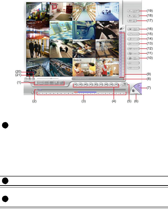
3.2Familiarizing the Buttons in Advanced/Preview Mode
Name |
Function |
|
|
(1) Exit |
Call up the Logout dialog box. |
|
In the logout dialog box, you may do the following: |
-Exit: To shutdown the DVR system.
-Reboot: Restart the DVR system.
-Login: To login in different account. Default user ID is admin and password is admin.
16

Name |
|
Function |
|||
|
|
|
|
|
|
(1) Exit |
|
- About: Display current DVR program version. User also can update the DVR program |
|||
|
|
firmware. Click the Update button and locate the firmware file to update. |
|||
|
|
|
|||
|
|
- Compact: Switch to compact mode |
|||
|
|
- |
Guest: Switch to the guest mode. In guest mode, the functions are limited to preview |
||
|
|
|
and playback function only. For complete functions of DVR, please login as an |
||
|
|
|
administrator authority level. |
||
|
|
- |
Cancel: To exit Logout dialog box |
||
|
|
|
|
||
(2) Split Screen Mode |
It provides 6 kinds of split display modes for your selection. You can select one of the split |
||||
|
|
display modes by clicking the following icon. |
|||
|
|
|
|
||
i |
- If there are only 4 cameras, you won’t be able to switch to 9, 13, and 16 split screen mode. |
||||
|
- The DVR system will save the current operating mode status (split screen mode, auto scan, and compact |
||||
|
mode status) when shutdown DVR application and apply the mode for next login. |
||||
|
- When you are in single screen mode, Right click and Drag a square on the area you want to enlarge. |
||||
|
- When you are in multiple-screen mode, Right click the video screen of the camera and Drag on where |
||||
|
you want to relocate it. |
||||
|
- To only display one of the video in the multiple-screen mode, Left click on the video screen you only |
||||
|
want to display. |
|
|
|
|
|
|
|
|
||
|
|
|
|
||
(3) Status Bar |
It shows the current time, system temperature, and the hard disk’s free space. |
||||
|
|
|
|
|
|
(4) Record |
To start recording. The button turns violet when it is recording. Click it again and enter the |
||||
|
|
|
|
||
|
|
password to stop. |
|||
|
|
|
|||
(5) EMap |
|
To load up to 8 desired Emaps in BMP or JPG image format, and locate cameras, |
|||
|
|
sensors, and relays to desired positions (see also Chapter 3.6). |
|||
|
|
|
|
|
|
(6) |
Network |
To allow inbound connections. When this function is enabled, the button turns violet. Click |
|
||
|
|
it again to disable all inbound connections. |
|
|
|
(7) |
Setup |
When setting up the system for the first time, type the login password in the Password text |
|
box to access. The default ID is admin and password is admin.
|
Click Setup ( |
) button to configure settings for cameras, recording, network, |
|||||
|
scheduler, backup, sensors, relays, alarms and user authentication. |
||||||
|
|
|
|
||||
(8) PTZ |
To call out a PTZ setup dialog to configure an appointed PTZ camera (see also Chapter |
||||||
|
3.5). |
|
|
|
|
|
|
|
|
|
|
|
|||
(9) Preview |
Switch to Preview mode. This allows you to view live camera display. Press ctrl + F can |
||||||
|
|
|
|
|
|
|
|
|
freeze the live preview video screen. And then, click Snapshot can save the freeze video |
||||||
|
screen. |
|
|
|
|
|
|
(10) Playback |
Switch to Playback mode. This allows you to view the recorded video file. (see Chapter |
||||||
|
3.3) |
|
|
|
|
|
|
|
|
|
|
|
|
|
|
17
Name |
Function |
|||||
|
|
|
|
|
|
|
(11) Camera Group |
To view the user defined channel group tree (see also Chapter 4.2.4). Click “+” of group to |
|||||
|
|
|
|
|
|
|
Tree |
extend group and drag the camera to surveillance screen to view. Click “+” of camera to |
|||||
|
view the camera information. |
|||||
|
|
|
|
|
|
|
|
|
|
|
|
|
|
|
|
|
|
|
|
|
|
|
|
|
|
|
|
(12) Camera ID |
Click a desired icon to play the desired channel. After you click the icon, it turns yellow. If |
||
|
you assign a split display mode and appoint a camera number, the icon group of the |
||
|
cameras will turn yellow altogether. |
||
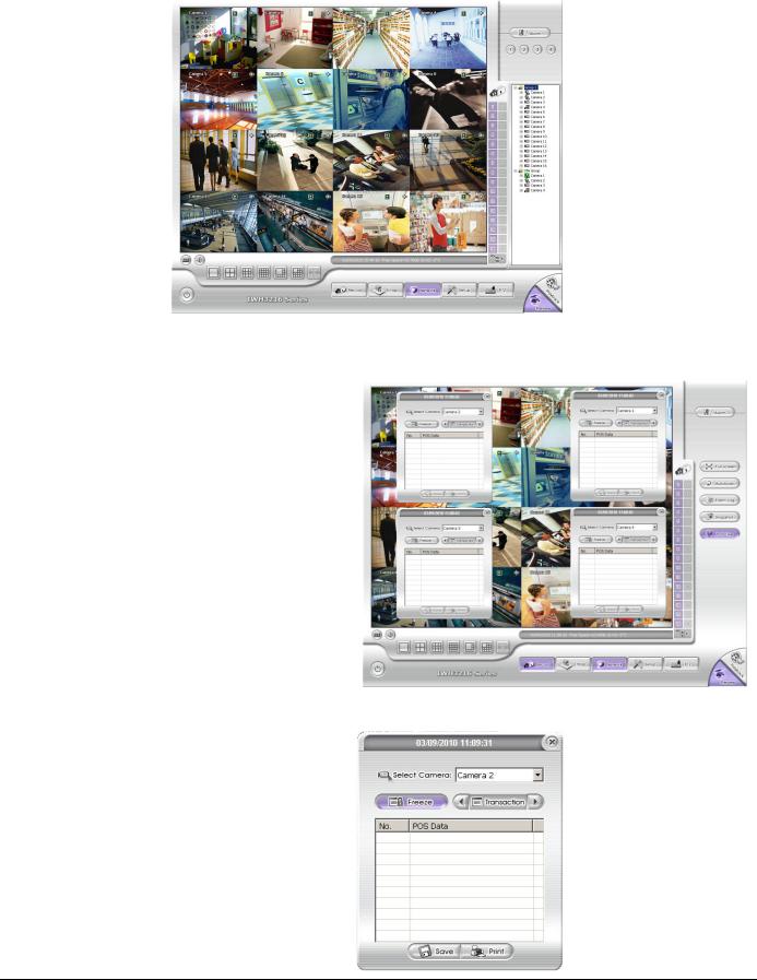
(13) iPOSLive |
To view the real time iPOS |
||
|
data of channels. Click the |
||
|
iPOSLive to call out the real |
||
|
time iPOS data windows. |
||
|
User can move the each |
||
|
channel of iPOS windows |
||
|
apart to proper position. If |
||
|
user didn’t enable the |
||
|
multi-channel of |
||
|
iPOSLive( see aslo iPOS |
||
|
Pro Setting in System |
||
|
Setting), and then, user |
||
|
should only can view one |
||
|
channel each time. |
||
|
To switch to different |
||
|
channel, click Select Camera drop down list to select the channel. To tempore stop iPOS |
||
|
data coming, click Freeze. To un-freeze, click Transaction. |
||
|
|
|
|
|
|
|
|
(14) Snapshot |
Catch a static recording image and save it as a BMP or a JPG file. |
|
|
18

Name |
Function |
|
|
|
|
(15) |
Event log |
Click it to pop-up the Event Log Viewer dialog to check Event, Operation, POS (Point of |
|
|
Sales), System and Network logs. You can select a desired date and a log item to show all |
|
|
logs data in the table. |
(16) |
AutoScan |
Click it to start Auto Scan. |
|
|
|
(17) |
Full screen |
Use the entire area of the screen to only display the video. To return, press the right button |
|
|
of the mouse or ESC on the keyboard or click the arrow icon. |
When you switch to full screen in multiple-screen mode, Left click to toggle to only display one of the video in the multiple-screen mode or all.
(18) |
Alarm |
Click Alarm Status ( |
) button to view the status or advanced alarm information. |
|||
|
|
|
|
|
||
(19) |
Live Playback |
If user has enabled the live playback function in System setup, the live playback icon |
||||
|
button |
should be seemed on the each channel of the preview screen(see also (9) Miscellaneous |
||||
|
|
in Chapter 4.1). |
|
|
||
|
|
Click |
to playback the recorded file instantly in preview mode. When the channel is in |
|||
|
|
live playback mode, the icon is |
. Move the mouse to the bottom of the live playback |
|||
|
|
channel, the playback tool bar ( |
) will show |
|||
|
|
up. Using the playback tool bar to control the playback. Total 4 channels can be live |
||||
|
|
playback at the same time. |
|
|
||
|
|
|
|
|
|
|
|
|
|
|
|
|
|
(20) |
Volume |
Adjust the audio volume to a proper volume. |
|
|
|
(21) |
On Screen |
If the keyboard is not available, you may use the Virtual Keyboard. |
|
Keyboard |
|
|
|
|
|
|
|
|
|
19 |
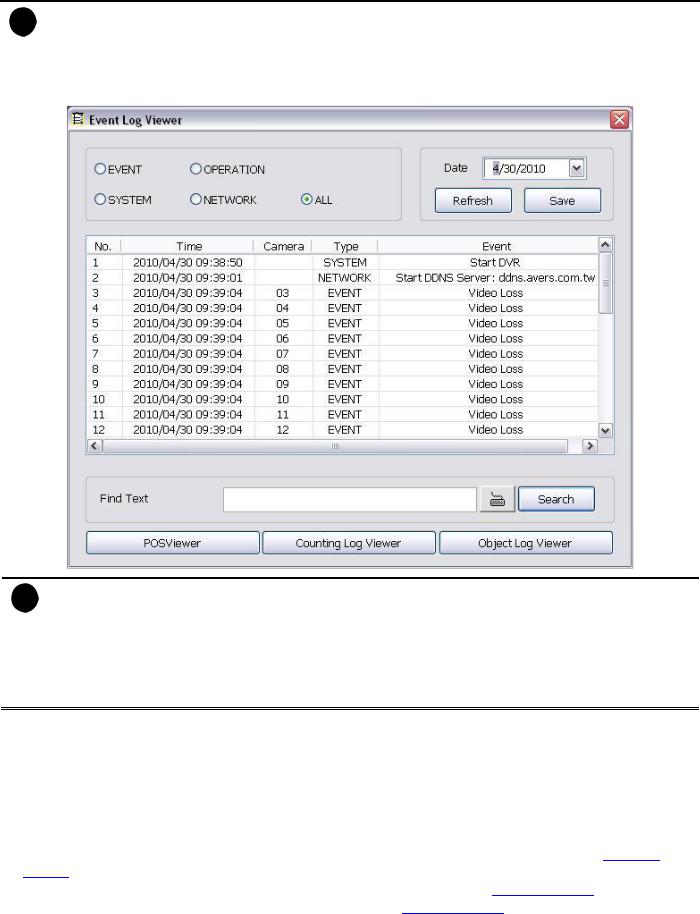
3.2.1Using Event Log Viewer
Show the record of activities that take place in the system.
i |
- |
DVR system supports HDD failure pre-detection mechanism called HDD S.M.A.R.T. function. Once when |
|
|
DVR system has detected the HDD failure possibility, an event log will be occurred and user can check it in |
|
|
Event Log Viewer window. |
|
- |
The HDD S.M.A.R.T. function accurate is approximately about 60%. |
|
- |
The HDD warming event log will issue once a day. |
|
|
|
i |
HDD S.M.A.R.T. warning messages’ description are as following: |
|
|
- |
HDD warning (Low risk): abnormal situations are occurred frequently but hard disk can recovery by itself. |
|
- |
HDD warning(High risk): When HDD warring(Low risk) event has occurred too frequently, even though |
|
|
hard disk can recovery by itself; however hard disk recovery too frequently will effect performance of hard |
|
|
disk. Therefore, it is recommended to replace the hard disk. |
[Note] HDD S.M.A.R.T. is an accumulation mechanism, therefore the HDD warning (High risk) event log will issue once every day until hard disk has been replaced.
1.Click the Event Log button on DVR system main interface. The Event log viewer window will show up.
2.Select the Date to view or search certain event log by key word. Enter the key word in Find Text column and click Search button.
3.To filter the records, select and click the select button to display Event, System, Operation, Network or All.
4.The event list which display on the screen can be saved as text file format. To save the event list, click Save button.
5.To view POS event log, click POSViewer bar to call out the POSViewer window (see also Chapter 3.2.1.1).
6.Click Counting Log Viewer to view object counting information (see also Chapter 3.2.1.2).
7.To view FaceFinder log, click Object Log Viewer (see also Chapter 3.2.1.3).
20

3.2.1.1Using POSViewer
(6)
(1)
(2)
(3)
(4)
(5)
|
|
|
|
|
Name |
Function |
|
|
|
|
|
|
|
|
(1) POSDB Path |
The storage path for POS event log. Click |
to change the storage path. |
|
|
|
|
|||
|
|
|
||
(2) Before/After |
Set a time period before and after of POS event log. |
|
||
(3) Channel |
Select the POS event log of channel |
|
|
|
|
|
|
||
(4) Search String |
Enter specific key word or word string to search the POS event log. Mark the “Match whole |
|
||
|
word exactly” box if wants to find exactly key word or word string of POS event log. |
|
||
|
|
|
|
|
(5)Export POSDB |
It allows user to save the POS database to selected storage path in excel format. Click |
to |
||
|
||||
|
change the storage path. Click Export to save the POSDB to selected storage path. |
|
||
|
|
|
|
|
(6) Full Reception |
Display the POS event log detail that user selected from Search Result window. Click |
to |
||
|
||||
|
save the POS event log. Click |
to print out the POS event log. |
|
|
(7) Search Result |
Display the POS event log of search result. Click |
to save the search result. Click |
to print |
|
|||
|
out the search result. |
|
|
|
|
|
|
21
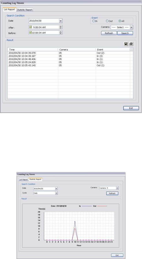
3.2.1.2Using Counting Log Viewer
Click Counting Log Viewer button on Event Log Viewer window to search and view the list and statistic report of object counting. If the object counting function is not enabling, there will be no any data to view. To setup object counting, please refer to Chapter 4.2.1.
1.Select the Date and set a time period between After and Before for object counts searching.
2.Select the search Event – In, Out or All.
3.Select one Camera or All cameras to search.
4.Click Search to start searching.
5.The result will be list out in Result table.
6.To save the search result, click .
.
7.Click  to print out the object counts log list.
8.To view the analysis of object counts, click Statistic Report tab.
9.User can select the Date, Camera, and Cycle to view the report of object counts (In/Out).
22

3.2.1.3Using the Object Viewer
Click Object Log Viewer button on Event Log Viewer window to view and search FaceFinder log. If the FaceFinder function is not enabling, there will be no any data to search and view. To setup FaceFinder, please refer to Chapter 4.2.2.
|
Name |
|
Function |
|
|
|
|
||
|
|
|
|
|
(1) Close |
|
Click to close Object Log Viewer window. |
||
|
|
|
||
(2) Search Mode |
|
Switch to face object log search mode. |
||
|
|
|
In search mode UI, select the Time and Camera |
|
|
|
|
to search the object log. The result will display at |
|
|
|
|
Object Log window. |
|
|
(3) Select Camera |
Select the camera to view or select all to view all |
|
|
|
|
cameras. |
|
|
|
|
|
(4) |
Clear |
To clear all object log in Object Log list. |
|
(5) |
Close up |
Click to close up the Object Log List window. |
|
(6) Object Log List |
Display the face object logs. It can display 32 |
|
|
|
|
object logs and when the list is full, the first row |
|
|
|
of object log will be replaced. |
|
|
|
|
23
3.3Familiarizing the Buttons in Playback Mode
To switch in Playback mode, click Playback button at the lower right corner of Preview mode user interface
|
Name |
|
Function |
|
|
|
|
|
|||
|
|
|
|
|
|
(1) |
Split Screen Mode |
|
Select from 6 kinds of split screen type to playback the recorded video file of all the |
||
|
|
|
|
camera, or one camera over the other or alongside on a single screen. |
|
|
|
|
|||
|
i |
If there are only 4 cameras enabled, you won’t be able to switch to 9, 13, and 16 split screen mode. |
|||
|
|
To zoom in an area on the screen, Right click and Drag a square on the area you want to enlarge. |
|||
|
|
|
|
||
|
|
|
|
||
(2) |
Progress bar |
|
Show the progress of the file being played. You may move the bar to seek at any |
||
|
|
|
|
location of the track. |
|
When in single screen playback mode, the colors in progress bar have different means.
Green color: a motion was detected and recorded
Blue color: is a general (always) recording file and no any event or motion happen during recording
Red color: the sensor was triggered while recording
Black color: no record file at the time period
Yellow color: the video loss happen while recording
iThe progress bar is designed and drawn based on key frame only.
(3) Hour Buttons |
Select and click to playback the recorded video file on the specific time frame. |
|
|
|
|
i |
The Hour buttons represent the time in 24-hour clock. The blue bar on top of the hour button indicates that |
|
|
there is a recorded video file on that period of time. While the red bar indicates that you are currently viewing |
|
the recorded video file.
24
 Loading...