


EH1116H-4 series
EH1116H-4 Nano/EH1116H-4 Nano+
EH1116H-4 Nano+-T
EH1116H-4+
User’s Manual
Oct. 2012
Manual Updates
Following are listed the new functions for the version H9.02.24.00.07 and above of EH1116H-4 series surveillance software.
Function |
Description |
Plug and Play |
DVR system supports AVer IP camera series to connect to DVR system without any |
(Camera Setting) |
configuration; user can use “search device” function to find the AVer series IP |
|
camera on your LAN network. |
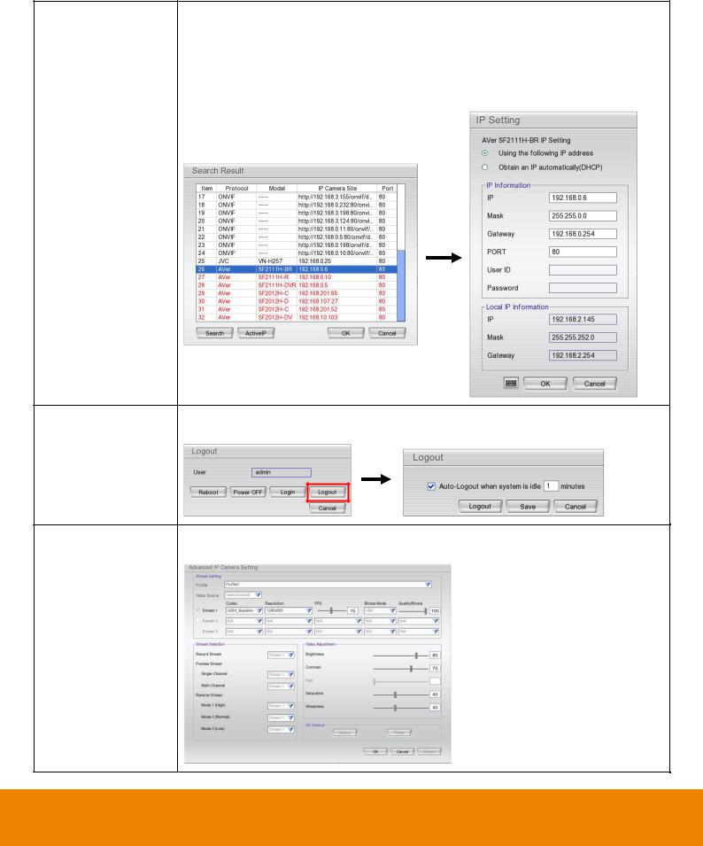
Active IP |
Allows user to configure the AVer IP camera series on DVR system; user doesn’t |
(Camera Setting) |
need to connect to IP camera on PC to configure the IP camera setting. |
Logout |
Allows user to set a system idle time to log out DVR system automatically. The idle |
|
time period rage is 1 to 60 minutes. |
ONVIF IP camera The DVR system supports IP camera’s detail setting on the IP camera is using advanced setting ONVIF protocol to connect it.
(Camera Setting)
i

Function |
Description |
|||||
Two way audio port |
Allows user to modify the port number for two-way audio. |
|||||
is configurable |
|
|
|
|
|
|
(Network Setting) |
|
|
|
|
|
|
|
|
|
|
|
|
|
|
|
|
|
|
|
|
|
|
|
|
|
|
|
Provides local |
The DVR system will transmit the DVR local information (IP, name of DVR, CPU |
|||||
information to CMS |
usage, free HDD capacity, recording status, video loss status, and estimate |
|||||
server |
recording day…etc) to CMS server. User can check the information that provides by |
|||||
|
DVR system at DVR Status on CMS server. |
|||||
Two-way audio on |
The two-way audio function is available on PCViewer. |
|||||
PCViewer |
|
|
|
|
|
|
|
|
|
|
|
|
|
|
|
|
|
|
|
|
|
|
|
|
|
|
|
User setting function |
The user setting function is available on Remote Setup. |
|||||
(Remote setup) |
|
|
|
|
|
|
|
|
|
|
|
|
|
|
|
|
|
|
|
|
|
|
|
|
|
|
|
ii

FCC NOTICE (Class A)
This device complies with Part 15 of the FCC Rules. Operation is subject to the following two conditions: (1) this device may not cause harmful interference, and (2) this device must accept any interference received, including interference that may cause undesired operation.
Federal Communications Commission Statement
NOTEThis equipment has been tested and found to comply with the limits for a Class A digital device, pursuant to Part 15 of the FCC Rules. These limits are designed to provide reasonable protection against harmful interference in a residential installation. This equipment generates uses and can radiate radio frequency energy and, if not installed and used in accordance with the instructions, may cause harmful interference to radio communications. However, there is no guarantee that interference will not occur in a particular installation. If this equipment does cause harmful interference to radio or television reception, which can be determined by tuning the equipment off and on, the user is encouraged to try to correct the interference by one or more of the following measures:
Reorient or relocate the receiving antenna.
Increase the separation between the equipment and receiver.
Connect the equipment into an outlet on a circuit different from that to which the receiver is connected.
Consult the dealer or an experienced radio/television technician for help.
Class A ITE
Class A ITE is a category of all other ITE which satisfies the class A ITE limits but not the class B ITE limits. Such equipment should not be restricted in its sale but the following warning shall be included in the instructions for use:
Warning -This is a class A product. In a domestic environment this product may cause radio interference in which case the user may be required to take adequate measures.
European Community Compliance Statement (Class A)
This product is herewith confirmed to comply with the requirements set out in the Council Directives on the Approximation of the laws of the Member States relating to Electromagnetic Compatibility Directive 2004/108/EEC.
Warning - This is a Class A product. In a domestic environment this product may cause radio interference in which case the user may be required to take adequate measures to correct this interference.
DISCLAIMER
No warranty or representation, either expressed or implied, is made with respect to the contents of this documentation, its quality, performance, merchantability, or fitness for a particular purpose. Information presented in this documentation has been carefully checked for reliability; however, no responsibility is assumed for inaccuracies. The information contained in this documentation is subject to change without notice.
In no event will AVer Information Inc. be liable for direct, indirect, special, incidental, or consequential damages arising out of the use or inability to use this product or documentation, even if advised of the possibility of such damages.
TRADEMARKS
“AVer” is a trademark owned by AVer Information Inc. Other trademarks used herein for description purpose only belong to each of their companies.
COPYRIGHT
© 2012 AVer Information Inc. All rights reserved.
No part of this document may be reproduced or transmitted in any form, or by any means without the prior written permission of AVer Information Inc. AVer Information Inc. reserves the rights to modify its models, including their characteristics, specifications, accessories and any other information stated herein without notice. The official printout of any information shall prevail should there be any discrepancy between the information contained herein and the information contained in that printout.
The mark of Crossed-out wheeled bin indicates that this product must not be disposed of with your other household waste. Instead, you need to dispose of the waste equipment by handing it over to a designated collection point for the recycling of waste electrical and electronic equipment. For more information about where to drop off your waste equipment for recycling, please contact your household waste disposal service or the shop where you purchased the product.
Battery Safety Information
-Store the batteries in a cool dry place.
-Do not dispose of used batteries in domestic waste. Dispose of batteries at special collection points or return to poin t of sale if applies.
-Remove the batteries during long periods of non-use. Always remove exhausted batteries from the remote control. Battery leakage and corrosion can damage this remote control, dispose of batteries safely.
-Do not mix old and new batteries.
-Do not mix different types of batteries: alkaline, standard (carbon-zinc) or rechargeable (nickel-cadmium).
-Do not dispose of batteries in a fire. The batteries may explode or leak.
-Never short circuit the battery terminals.
3

WARNING
TO REDUCE RISK OF FIRE OR ELECTRIC SHOCK, DO NOT EXPOSE THIS APPLIANCE TO RAIN OR MOISTURE
CAUTION
IF THERE IS ANY DAMAGE, SHORTAGE OR INAPPROPRIATE ITEM IN THE PACKAGE, PLEASE CONTACT WITH YOUR LOCAL DEALER. WARRANTY VOID FOR ANY UNAUTHORIZED PRODUCT MODIFICATION
NOTICE
-INFORMATION IN THIS DOCUMENT IS SUBJECT TO CHANGE WITHOUT NOTICE.
-THE INFORMATION CONTAINED HEREIN IS TO BE CONSIDERED FOR REFERENCE ONLY.
Table of Contents
Manual Updates................................................................................................................................................ |
i |
|||
Chapter 1 |
Introduction.............................................................................................................................. |
1 |
||
1.1 |
|
Package Content ................................................................................................................................ |
1 |
|
1.1.1 EH1116H-4 Nano/EH1116H-4 Nano+/EH1116H-4 Nano+-T ............................................................ |
1 |
|||
1.1.2 EH1116H-4+ ................................................................................................................................... |
2 |
|||
1.1.3 |
|
Optional Accessories ..................................................................................................................... |
2 |
|
1.2 |
|
Front Panel......................................................................................................................................... |
3 |
|
1.2.1 |
|
EH1116H-4 Nano ........................................................................................................................... |
3 |
|
1.2.2 |
|
EH1116H-4 Nano+.......................................................................................................................... |
4 |
|
1.2.3 |
|
EH1116H-4 Nano+-T ...................................................................................................................... |
6 |
|
1.2.4 EH1116H-4+ ................................................................................................................................... |
7 |
|||
|
1.2.4.1 To Set a Video Segment and Save.......................................................................................... |
9 |
||
1.3 |
|
Back Panel ....................................................................................................................................... |
10 |
|
1.3.1 EH1116H-4 Nano/EH1116H-4 Nano+/EH1116H-4 Nano+-T .......................................................... |
10 |
|||
1.3.2 EH1116H-4+ .................................................................................................................................. |
11 |
|||
1.4 |
Setting Up the DVR Unit ................................................................................................................... |
12 |
||
1.4.1 Installing the Hard Disk ................................................................................................................ |
12 |
|||
|
1.4.1.1 EH1116H-4 Nano/EH1116H-4 Nano+/EH116H-4 Nano+-T ..................................................... |
12 |
||
|
1.4.1.2 EH1116H-4+ .......................................................................................................................... |
14 |
||
1.4.2 |
|
Connecting Devices..................................................................................................................... |
16 |
|
|
1.4.2.1 EH1116H-4 Nano/EH1116H-4 Nano+/EH1116H-4 Nano+-T.................................................... |
16 |
||
|
1.4.2.2 EH1116H-4+ .......................................................................................................................... |
18 |
||
1.5 |
Audio, Sensor, Relay and RS485 pinhole allocation ......................................................................... |
19 |
||
1.5.1 Audio Out Pin Definition............................................................................................................... |
19 |
|||
1.5.2 |
|
Sensor Pin Definition ................................................................................................................... |
19 |
|
1.5.3 |
|
Relay Pin Definition ..................................................................................................................... |
19 |
|
1.5.4 |
|
RS485 Pin Definition.................................................................................................................... |
20 |
|
1.6 |
Familiarizing the Remote Control Buttons......................................................................................... |
21 |
||
1.7 |
Updating the DVR System Firmware ................................................................................................ |
24 |
||
1.7.1 |
|
USB Recovery ............................................................................................................................. |
24 |
|
1.7.2 |
|
Local UI Upgrading ...................................................................................................................... |
27 |
|
1.7.3 |
|
Remote ISP Upgrading ................................................................................................................ |
30 |
|
Chapter 2 |
Using the DVR Software ........................................................................................................ |
33 |
||
2.1 |
First Time Using the DVR Unit .......................................................................................................... |
33 |
||
2.1.2 Using the Virtual Keyboard .......................................................................................................... |
35 |
|||
2.2 |
Familiarizing the Buttons in Preview Mode ....................................................................................... |
36 |
||
|
|
|
|
|
|
|
|
|
|
2.2.1 |
|
To Setup DVR System Logout Time............................................................................................. |
39 |
|
2.2.2 |
|
Setting Up and Using the Emap................................................................................................... |
40 |
|
2.2.3 |
|
Familiarizing the Buttons in PTZ Camera Controller .................................................................... |
41 |
|
2.2.3.1 |
Setup the Analog PTZ Camera............................................................................................ |
42 |
||
2.2.3.2 |
Setup the IP PTZ Camera ................................................................................................... |
43 |
||
2.2.4 |
|
Using Event Log Viewer............................................................................................................... |
44 |
|
2.2.4.1 |
|
Using POSViewer ...................................................................................................................... |
45 |
|
2.3 |
Familiarizing the Buttons in Playback Mode...................................................................................... |
46 |
||
2.3.1 |
|
To Cut and Save a Portion of the Recorded Video ....................................................................... |
48 |
|
2.3.2 |
|
To Bookmark a Video Section ...................................................................................................... |
49 |
|
2.3.3 |
|
To Search Using Visual Search.................................................................................................... |
50 |
|
2.3.4 |
|
Using the Event Search ............................................................................................................... |
52 |
|
Chapter 3 |
|
Customizing the DVR System ............................................................................................... |
53 |
|
3.1 |
System Setup ................................................................................................................................... |
53 |
||
3.2 |
Camera Setup .................................................................................................................................. |
59 |
||
3.2.1 |
|
To Setup IP Camera(Fixed Mode)................................................................................................ |
59 |
|
3.2.2 |
|
To Setup IP Camera(Flexible Mode) ............................................................................................ |
63 |
|
3.2.2.1 |
Using Search Device to Connect IP Camera................................................................................ |
69 |
||
3.2.3 |
|
To Setup Analog Camera ............................................................................................................. |
71 |
|
3.2.4 |
|
To Setup Camera from the Remote DVR(Fixed Mode) ................................................................ |
72 |
|
3.2.5 |
|
To Setup Camera from the Remote DVR(Flexible Mode) ............................................................. |
74 |
|
3.3 |
Recording Setup............................................................................................................................... |
77 |
||
3.3.1 |
|
Setup IP Camera Record Setting ................................................................................................. |
77 |
|
3.3.2 |
|
Setup Analog Camera Record Setting ......................................................................................... |
78 |
|
3.4 |
Network Setup.................................................................................................................................. |
80 |
||
3.5 |
Schedule Setting .............................................................................................................................. |
84 |
||
3.6 |
Backup Setup ................................................................................................................................... |
85 |
||
3.6.1 |
|
Using QPlayer to Playback Backup Video.................................................................................... |
87 |
|
3.6.2 |
|
To Cut and Save the Portion of the Recorded Video .................................................................... |
90 |
|
3.6.3 |
|
To Search Using the Visual Search.............................................................................................. |
90 |
|
3.6.4 |
|
To Search Using the Event Search .............................................................................................. |
91 |
|
3.6.5 |
|
To Search Using the Intelligent Search ........................................................................................ |
92 |
|
3.7 |
Sensor Setting .................................................................................................................................. |
93 |
||
3.8 |
Relay Setting .................................................................................................................................... |
94 |
||
3.10 |
Alarm Setting .................................................................................................................................... |
95 |
||
3.11 |
User Setup ..................................................................................................................................... |
102 |
||
Chapter 4 |
|
Using the Remote Programs ............................................................................................... |
105 |
|
4.1 |
Familiarizing the Buttons in PCViewer ............................................................................................ |
106 |
||
|
|
|
|
|
|
|
|
|
|

|
|
|
CONTENTS |
4.1.1 |
PCViewer Screen ...................................................................................................................... |
106 |
|
4.1.2 |
PCViewer Control Panel ............................................................................................................ |
108 |
|
4.1.3 |
Playback Mode Control Panel..................................................................................................... |
110 |
|
4.1.4 To Setup Remote System Setting ............................................................................................... |
112 |
||
4.1.4.1 |
System Setting..................................................................................................................... |
112 |
|
4.1.4.2 |
Camera Setting .................................................................................................................... |
114 |
|
4.1.4.3 |
Record Setting ..................................................................................................................... |
118 |
|
4.1.4.4 |
Network Setting................................................................................................................... |
122 |
|
4.1.4.5 |
Alarm Setting ...................................................................................................................... |
124 |
|
4.1.4.6 |
User Setup.......................................................................................................................... |
128 |
|
4.2 |
Familiarizing the Buttons in Remote Console ................................................................................. |
130 |
|
4.2.1 To Setup Remote Console Setting ............................................................................................. |
131 |
||
4.3 |
Using the Remote Playback ........................................................................................................... |
132 |
|
4.3.1 Familiarizing the Buttons in Local Playback ............................................................................... |
133 |
||
4.3.1.1 To Cut and Save the Wanted Portion of the Recorded Video .............................................. |
135 |
||
4.3.1.2 To Search Using the Visual Search ..................................................................................... |
136 |
||
4.3.1.3 To Search Using the Intelligent Search................................................................................ |
136 |
||
4.3.2 Familiarizing the Buttons in RealTime Playback......................................................................... |
137 |
||
4.3.3 Familiarizing the Buttons in Download and Playback ................................................................. |
139 |
||
Chapter 5 |
Using the Web Tools............................................................................................................ |
141 |
|
5.1 |
Remote iSetup................................................................................................................................ |
141 |
|
5.1.1 |
To Add DVR server .................................................................................................................... |
141 |
|
5.1.2 To Setup Remote System Setting .............................................................................................. |
142 |
||
5.2 |
Remote iBackup ............................................................................................................................. |
143 |
|
5.2.1 To back up the recoded data from the DVR server..................................................................... |
143 |
||
Appendix A |
Registering Domain Name.................................................................................................... |
146 |
|
Appendix B |
Network Service Port............................................................................................................ |
148 |
|
|
|
|
|
|
|
|
|
CHAPTER 1
Chapter 1 |
Introduction |
EH1116H-4 series are included 2 models – EH1116H-4 Nano series and EH1116H-4+.
EH1116H-4 Nano series has 3 models –EH1116H-4 Nano, EH1116H-4 Nano+, and EH1116H-4 Nano+-T. EH1116H-4 Nano series is a 16CH H.264 embedded hybrid DVR with mini-fan design which is ideal for space and noise critical applications.
EH1116H-4+ is a 16CH H.264 embedded hybrid DVR with up to 2 HDDs supported and is an ideal selection for medium scale and retail security projects.
EH1116H-4 series employ full hybrid functionalities such as intelligent streaming, advanced live alarm mechanisms, POS integration, and remote software integration. Easy operation, low maintenance, and full functionalities makes the EH1116H-4 series perfect for deployments in small to mid-sized installations, including retails and small-sized business.
1.1Package Content
1.1.1 EH1116H-4 Nano/EH1116H-4 Nano+/EH1116H-4 Nano+-T
a. |
b. |
c. |
|
(3) |
|||
|
|
||
|
|
(1) |
|
|
(5) |
(6) |
||
|
(2) |
(4) |
|||
|
|
|
|||
|
|
|
|
||
|
|
|
|
(7) |
|
|
|
|
|
(8) |
|
(1) |
DVR unit |
|
(5) |
Power cable (*The power cable may vary according to |
|
|
a. EH1116H-4 Nano |
b. EH1116H-4 Nano+ |
|
the local electricity system.) |
|
|
+ |
-T |
(6) |
Screws for internal HDD installation |
|
|
c. EH1116H-4 Nano |
(7) |
Remote Control |
||
(2) |
Quick Installation Guide |
||||
(8) |
DVI cable |
||||
(3) |
Software CD (Manual is included) |
||||
|
|
||||
(4) |
Power adaptor |
|
|
|
|
1

1.1.2 EH1116H-4+
(1)  (5)
(5)
(2) |
(3) |
(4) |
|
||
|
|
|
(6) |
|
|
(9) |
|
(7) |
(8) |
|
|
|
|
|
|
|
(1) |
EH1116H-4+ unit |
|
(6) |
Screws for internal HDD installation |
(2) |
Quick Installation Guide |
|
(7) |
Remote Control |
(3) |
Software CD (Manual is included) |
|
(8) |
DVI cable |
(4) |
Power adaptor |
|
(9) |
SATA cable for HDD |
(5) |
Power cable (*The power cable may vary according to |
|
|
|
|
the local electricity system.) |
|
|
|
1.1.3 Optional Accessories
IR extended cable
2

CHAPTER 1
1.2Front Panel
1.2.1 EH1116H-4 Nano
|
Name |
|
Function |
|
|
|
|
|
|||
|
|
|
|
|
|
(1) |
System Power |
|
System power status indicators. Lights when the system is running. |
||
|
|
indicator |
|
||
|
|
|
|
|
|
|
|
|
|
||
(2) |
Record indicator |
|
When DVR system is recording, the light will keep flashing. |
||
|
|
|
|
||
(3) |
IR Sensor |
|
Receive signal from the remote control to operate the DVR unit |
||
|
|
|
|
||
(4) |
IR Sensor port |
|
For extended IR sensor cable(optional) |
||
|
|
|
|
||
(5) |
USB port(mouse) |
|
For USB mouse connection. |
||
|
|
|
|
|
|
|
|
|
|
For connecting USB device, ex: USB pen drive, external hard disk, mouse…and so on. |
|
(6) USB port
i |
The USB backup device must be in FAT32 format. |
|
|
3

1.2.2 EH1116H-4 Nano+
|
Name |
|
|
Function |
|
|
|
|
|
|
|||
(1) |
System Power |
|
|
System power status indicators. Indicate running state of system. Lights when the system is |
||
|
|
indicator |
|
|
running. |
|
|
|
|
|
|
||
(2) |
Record indicator |
|
|
When DVR system is recording, the light will keep flashing. |
||
|
|
|
|
|
||
(3) |
IR Sensor |
|
|
Receive signal from the remote control to operate the DVR unit |
||
|
|
|
|
|
||
(4) |
IR Sensor port |
|
|
For extended IR sensor cable(optional) |
||
|
|
|
|
|
||
(5) |
USB port(mouse) |
|
|
For USB mouse connection. |
||
|
|
|
|
|
|
|
|
|
|
|
|
For connecting USB device, ex: USB pen drive, external hard disk, mouse…and so on. |
|
(6) |
USB port |
|
|
|
|
|
|
|
i The USB storage device must be in FAT32 format. |
||||
|
|
|
|
|
||
|
|
|
|
|
||
|
|
|
|
|
||
(7) |
|
|
|
Switch to playback mode. Press again can switch back to preview mode. |
||
|
|
|
|
|
||
(8) |
|
|
|
Start to recording. |
||
|
|
|
|
|
||
(9) |
|
|
|
To call out setup menu. |
||
|
|
|
|
|||
(10) |
|
|
Press it to enter or make a selection. |
|||
Temporarily freeze the video playback.
Stop video playback. When user press stop button, the DVR will switch back to preview mode.
Wind back the playback video.
(11)
Fast play the video playback at the speed of 2x, 4x, 8x,16x, 32x, or 64x.
To play the recorded video.
4

CHAPTER 1
|
Name |
|
|
Function |
|
||||
|
|
|
|
||||||
|
|
|
|
|
|
|
|
|
|
|
|
|
|
|
|
|
|
Move the mouse cursor to left. |
|
|
|
|
|
|
|
|
|
|
|
|
|
|
|
|
|
|
|
Move the mouse cursor to right. |
|
(12) |
|
|
|
|
|
|
|
|
|
|
|
Move the mouse cursor up. |
|||||||
|
|
|
|
|
|
|
|
||
|
|
|
|
|
|
|
|
|
|
|
|
|
|
|
|
|
|
Move the mouse cursor down. |
|
|
|
|
|
|
|
|
|
||
(13) |
|
|
|
|
|
|
Switch a channel by channel. |
||
|
|
|
|
|
|
|
|
|
|
(14) |
|
|
|
|
|
|
Switch to different screen display mode (single, 4-split screen, 9-split screen, and 7+1 split |
||
|
|
|
|
|
|
||||
|
|
|
|
|
|
screen). |
|||
|
|
|
|
|
|||||
|
|
|
|
|
|
|
|
||
|
|
|
|
|
|
|
|
|
|
5

1.2.3 EH1116H-4 Nano+-T
|
Name |
|
Function |
|
|
|
|
|
|||
(1) |
System Power |
|
System power status indicators. Indicate running state of system. Lights when the system is |
||
|
|
indicator |
|
running. |
|
|
|
|
|
||
(2) |
Record indicator |
|
When DVR system is recording, the light will keep flashing. |
||
|
|
|
|
||
(3) |
IR Sensor |
|
Receive signal from the remote control to operate the DVR unit |
||
|
|
|
|
||
(4) |
IR Sensor port |
|
For extended IR sensor cable(optional) |
||
|
|
|
|
||
(5) |
USB port(mouse) |
|
For USB mouse connection. |
||
|
|
|
|
|
|
|
|
|
|
For connecting USB device, ex: USB pen drive, external hard disk, mouse…and so on. |
|
(6) USB port
i |
The USB storage device must be in FAT32 format. |
|
|
|
|
Temporarily freeze the video playback.
Stop video playback. When user press stop button, the DVR will switch back to preview mode.
(7) |
|
|
Wind back the playback video. |
|
|||
|
|
|
|
Fast play the video playback at the speed of 2x, 4x, 8x,16x, 32x, or 64x.
|
|
|
|
|
To play the recorded video. |
|
|
|
|
|
|
|
|
|
|
|
|
|
Move the mouse cursor to left. |
|
|
|
|
|
|
|
|
|
|
|
|
|
Move the mouse cursor to right. |
|
(8) |
|
|
|
|
|
|
Move the mouse cursor up. |
||||||
|
|
|
|
|
||
|
|
|
|
|
|
|
|
|
|
|
|
Move the mouse cursor down. |
|
|
|
|
|
|
|
|
(9) |
|
|
|
|
Press it to enter or make a selection. |
|
|
|
|
|
|
|
|
(10) |
|
|
|
|
Start to recording. |
|
|
|
|
|
|
|
|
(11) |
|
|
|
|
Switch to different screen display mode (single, 4-split screen, 9-split screen, and 7+1 split |
|
|
|
|
|
|||
|
|
|
|
|||
|
|
|
|
|||
|
|
|
|
|||
|
|
|
|
screen). |
||
|
|
|
|
|
||
|
|
|
|
|
|
|
(12) |
|
|
|
|
Switch a channel by channel. |
|
|
|
|
|
|
|
|
(13) |
|
|
|
|
Switch to playback mode. Press again can switch back to preview mode. |
|
|
|
|
|
|
|
|
(14) |
|
|
|
|
To call out setup menu. |
|
|
|
|
|
|
|
6
CHAPTER 1
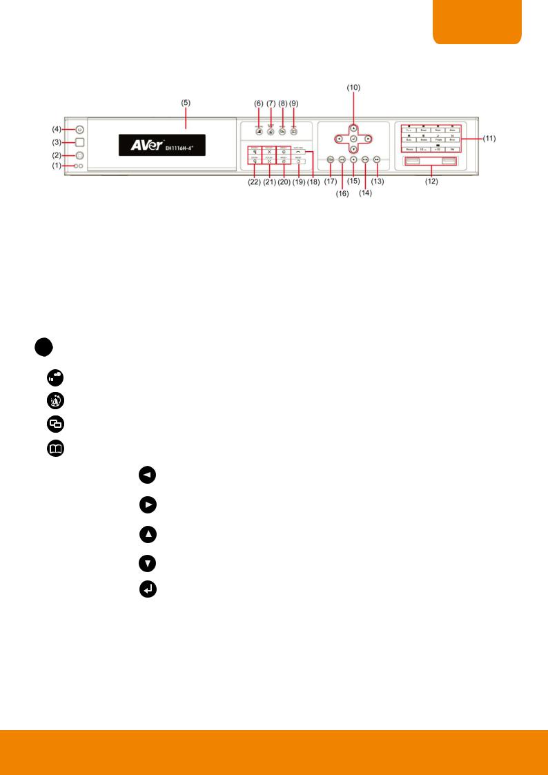
1.2.4 EH1116H-4+
|
Name |
|
|
|
Function |
|
||
|
|
|
|
|
||||
|
|
|
|
|
|
|
Power indicator: System power status indicators. Indicate running state of system. Lights |
|
(1) |
System indicator |
|
|
when the system is running. |
||||
|
|
|
|
|||||
|
|
Recording indicator: When DVR system is recording, the light will keep flashing. |
||||||
|
|
|
|
|
|
|
||
|
|
|
|
|
|
|||
(2) |
IR Sensor port |
|
|
For extended IR sensor cable(optional) |
||||
|
|
|
|
|
|
|||
(3) |
IR Sensor |
|
|
Receive signal from the remote control to operate the DVR unit |
||||
|
|
|
|
|
|
|||
(4) |
Power |
|
|
ON/OFF DVR unit |
||||
|
|
|
|
|
|
|||
(5) |
DVD+RW |
|
|
To backup the recorded file to DVD±R/DVD±RW disk |
||||
|
|
|
|
|||||
|
i |
DVD+RW is an optional accessory. User need to purchase additional. |
||||||
|
|
|
|
|
|
|
||
|
|
|
|
|
|
|
||
(6) |
|
|
|
|
|
To enable/ disable recording video |
||
|
|
|
|
|
||||
|
|
|
|
|
|
|
||
(7) |
|
|
|
|
|
To reset alarm status |
||
|
|
|
|
|
|
|
||
(8) |
|
|
|
|
|
Switch between playback mode and preview mode |
||
|
|
|
|
|
|
|
|
|
|
|
|
|
|
|
|
Call out system setup menu on preview mode |
|
(9) |
|
|
|
Call out playback menu on playback mode |
|||
|
|||
|
|
Move to left direction on menu control |
|
|
|
|
|
|
|
To move PTZ camera lens to left in PTZ mode |
|
|
|
|
|
|
|
Move to right direction on menu control |
|
|
|
|
|
|
|
To move PTZ camera lens to right in PTZ mode |
|
|
|
|
|
(10) Control Buttons |
|
To move PTZ camera lens to up |
|
|
|
||
|
|
Move to up direction on menu control |
|
|
|
|
|
|
|
To move PTZ camera lens to down |
|
|
|
|
|
|
|
Move to down direction on menu control |
|
|
|
|
|
|
|
Confirm or make a selection |
|
|
|
|
|
7

|
Name |
|
Function |
|
|
|
|
||
|
|
|
|
|
|
|
|
- Channel camera selection number in |
playback and |
|
|||||||||||
|
|
|
|
preview mode. For the channel over 10, press |
|
, |
||||||||||
|
|
|
|
|
||||||||||||
|
~ |
|
|
then press |
|
|
|
~ |
|
|
|
|
|
|
|
|
|
|
|
|
|
|
|
|
|
|
|
|
|
||||
|
|
|
|
|
|
|
|
|
|
|
|
|
||||
|
|
|
|
|
|
|
|
|
|
|
|
|
|
|
|
|
|
|
- |
Press |
|
|
|
button can switch to different screen |
|
||||||||
|
|
|
|
|
|
|||||||||||
|
|
|
|
|
|
|||||||||||
|
|
|
|
display modes ( |
|
|
~ |
|
|
). |
|
|
||||
|
|
|
|
|
|
|
|
|
|
|
|
|||||
|
|
|
|
|
|
|
|
|
|
|
|
|
|
|
|
|
-Press  and number button, to set the preset position in the PTZ mode.
A functional key for multiple system control. Press |
|
to enable |
||||
multiple function modes and the |
|
|
button will light up blue. To exit |
|||
|
|
|
|
|
|
|
multiple function modes, press |
|
|
again. |
|
|
|
|
|
|
|
|
|
|
(11) Number buttons |
|
|
|
|
|
+ |
|
|
|
|
|
|
|
|
: Switch to single screen display mode |
|||||||||
|
|
|
|
|
|
|
|
|
|
|
|
|
||||||||||||
|
|
|
|
|
|
|
|
|
|
|
|
|
|
|
|
|
|
|||||||
|
|
|
|
|
|
|
|
|
|
|
|
|
|
|
|
|
|
: Switch to QUAD display mode |
||||||
|
|
|
|
|
|
|
|
|
|
|
|
|
|
|
|
|
|
|||||||
|
|
|
|
|
|
|
|
|
|
|
+ |
|
|
|
|
|
|
|
|
|||||
|
|
|
|
|
|
|
|
|
|
|
|
|
|
|
|
|
|
|
||||||
|
|
|
|
|
|
|
|
|
|
|
|
|
|
|
|
|
|
|||||||
|
|
|
|
|
|
|
|
|
|
|
|
|
|
|
|
|
|
|
: Switch to 9 spilt screen display mode |
|||||
|
|
|
|
|
|
|
|
|
|
|
|
|
|
|
|
|
|
|
||||||
|
|
|
|
|
|
|
|
|
|
|
+ |
|
|
|
|
|
|
|
|
|||||
|
|
|
|
|
|
|
|
|
|
|
|
|
|
|
|
|
|
|||||||
|
|
|
|
|
|
|
|
|
|
|
|
|
|
|
|
|
|
|
|
: Switch to 16 split screen display mode |
||||
|
|
|
|
|
|
|
|
|
|
|
|
|
|
|
|
|
|
|
|
|||||
|
|
|
|
|
|
|
|
|
|
|
|
|
|
|
|
|
|
|||||||
|
|
|
|
|
|
|
|
|
|
+ |
|
|
|
|
|
|
|
|
||||||
|
|
|
|
|
|
|
|
|
|
|
|
|
|
|
|
|
|
|||||||
|
|
|
|
|
|
|
|
|
|
|
|
|
|
|
|
|
|
|
: Switch to one single and 7 + 1 spilt screen display |
|||||
|
|
|
|
|
|
|
|
|
|
|
|
|
|
|
|
|
|
|||||||
|
|
|
|
|
|
|
|
|
|
+ |
|
|
|
|
|
|
|
|
||||||
|
|
|
|
|
|
|
|
|
|
|
|
|
|
|
|
|
|
|||||||
|
|
|
|
|
|
|
|
|
|
|
|
|
|
|
|
|
|
|
|
|||||
|
|
|
|
|
|
|
|
|
mode |
|
|
|
|
|
||||||||||
|
|
|
|
|
|
|
|
|
|
|
|
|
|
|
|
: Switch to one single and 12+ 1 spilt screen display |
||||||||
|
|
|
|
|
|
|
|
|
+ |
|
|
|
|
|
|
|
|
|||||||
|
|
|
|
|
|
|
|
|
|
|
|
|
|
|
|
|
|
|||||||
|
|
|
|
|
|
|
|
|
|
|
|
|
|
|
|
|
|
|||||||
|
|
|
|
|
|
|
|
|
mode |
|
|
|
|
|
||||||||||
|
|
|
|
|
|
|
|
|
|
|
|
|
|
|
|
: Enable/disable channel auto switch cycle |
||||||||
|
|
|
|
|
|
|
|
|
+ |
|
|
|
|
|
|
|
|
|||||||
|
|
|
|
|
|
|
|
|
|
|
|
|
|
|
|
|
|
|||||||
|
|
|
|
|
|
|
|
|
|
|
|
|||||||||||||
|
|
|
|
|
|
|
|
|
|
|||||||||||||||
(12) USB 2.0 port |
2 x USB 2.0 ports for connecting USB device, ex: USB pen drive, external hard disk, |
|||||||||||||||||||||||
mouse…and so on. |
|
|
|
|
|
|||||||||||||||||||
|
|
|
|
|
|
|
|
|
|
|
||||||||||||||
(13) |
|
|
|
|
|
To playback video at faster speed |
|
|
|
|
|
|||||||||||||
|
|
|
|
|
|
|
|
|
|
|
|
|||||||||||||
(14) |
|
|
|
|
|
To pause playback |
|
|
|
|
|
|||||||||||||
|
|
|
|
|
To start playback |
|
|
|
|
|
||||||||||||||
|
|
|
|
|
|
|
|
|
|
|
||||||||||||||
|
|
|
|
|
|
|
|
|
|
|
|
|||||||||||||
(15) |
|
|
|
|
|
To rewind the recorded video |
|
|
|
|
|
|||||||||||||
|
|
|
|
|
|
|
|
|
|
|
||||||||||||||
(16) |
|
|
|
|
|
Set a video segment to playback repeat(see also Chapter 1.2.3.1) |
|
|
|
|||||||||||||||
|
|
|
|
|
|
|
|
|
|
|||||||||||||||
(17) |
|
|
|
|
|
To backup recorded video file to USB storage device(pen drive or external hard disk) and |
||||||||||||||||||
|
|
|
|
|
DVD-ROM. |
|
|
|
|
|
||||||||||||||
|
|
|
|
|
|
|
|
|
|
|
||||||||||||||
|
|
|
|
|
|
Operate the PTZ cameras automatically based on the selected camera group preset position |
||||||||||||||||||
(18) |
|
|
|
|
|
number. |
|
|
|
|
|
|||||||||||||
|
|
|
|
|
|
|
|
|
|
|||||||||||||||
|
|
|
|
|
|
|
|
|
|
|
|
|
|
|
|
|
|
|
|
|
|
|
|
|
|
|
|
|
|
i |
Without setup preset position, the preset button ( |
|
|
) will not be functional |
|||||||||||||||
|
|
|
|
|
|
|
|
|||||||||||||||||
|
|
|
|
|
|
|
|
|||||||||||||||||
|
|
|
|
|
|
|
when press it.. |
|
|
|
|
|
||||||||||||
|
|
|
|
|
|
|
|
|
|
|||||||||||||||
|
|
|
|
|
|
|
|
|
|
|||||||||||||||
(19) |
|
|
|
|
|
Adjust the PTZ lens to the position that user wants. And then, press |
|
|
with |
|||||||||||||||
|
|
|
|
|
|
|
||||||||||||||||||
|
|
|
|
|
|
|||||||||||||||||||
|
|
|
|
|
number button to setup the PTZ camera preset position. |
|
|
|
||||||||||||||||
|
|
|
|
|
|
|
|
|||||||||||||||||
|
|
|
|
|
|
|
|
|
||||||||||||||||
|
|
|
|
|
|
|
|
|
|
|
|
|
|
|
|
|
|
|
|
|
|
|
|
|
8

CHAPTER 1
|
Name |
|
Function |
|
||||
|
|
|
||||||
|
|
|
|
|
|
|
|
|
|
|
|
|
|
|
|
To speed up movement of PTZ camera lens |
|
|
|
|
|
|
|
|
||
(20) |
Speed + / Speed - |
|
|
|
|
To speed down movement of PTZ camera lens |
||
|
|
|
|
|
|
|
||
|
|
|
|
|
|
|
||
|
|
|
|
|
|
|
|
|
|
|
|
|
|
|
|
To focus in PTZ camera lens |
|
|
|
|
|
|
|
|
||
(21) |
Focus + / Focus - |
|
|
|
|
|
|
|
|
|
|
|
|
|
|
To focus out PTZ camera lens |
|
|
|
|
|
|
|
|
||
|
|
|
|
|
|
|
|
|
|
|
|
|
|
|
|
To zoom in view of PTZ camera lens |
|
|
|
|
|
|
|
|
||
(22) |
Zoom + / Zoom - |
|
|
|
|
To zoom out view of PTZ camera lens |
||
|
|
|
|
|
|
|
||
|
|
|
|
|
|
|
||
|
|
|
|
|
|
|
|
|
1.2.4.1 To Set a Video Segment and Save
Keep a portion of the recorded video. Following the below steps to Set and Save the Wanted Portion of the Recorded Video
1.While playback, press  button and the A point of video segment is set. User should see the word “A-“on upper right of surveillance screen.
2.Press  again to set B point of video segment. User should see the word “A-B“ on upper right of surveillance screen.
3.The DVR system will start repeat playback the video segment that user has set until user cancel the video segment. Press  again or right-click on playback screen will cancel the video segment.
4.To save the video segment, left-click on the channel screen that user wants to save to switch to single screen mode.
5.And then, Plug in the pen drive device.
6.Click Segment button on Playback UI. The Output Video Clip dialog is displayed.
7.Click Save to output the video segment to USB storage device. Mark Include Player when backup option to include the Qplayer application in output video segment folder for playback.
9

1.3Back Panel
1.3.1 EH1116H-4 Nano/EH1116H-4 Nano+/EH1116H-4 Nano+-T
|
Name |
|
Function |
|
|
|
|
|
|||
(1) |
Spot Monitor |
|
Outputs the analog video signals to SPOT monitor when receive the alarm events. |
||
|
|
|
|
||
(2) |
TV Output |
|
Outputs the video signals to a TV monitor. |
||
|
|
|
|
||
(3) |
Video Input |
|
Input the video camera signal (Channel1~16). |
||
|
|
|
|
||
(4) |
VGA Output |
|
Outputs the camera video signal to a LCD monitor. |
||
|
|
|
|
||
(5) |
eSATA port |
|
For connecting with eSATA RAID. |
||
|
|
|
|
||
(6) |
LAN Port |
|
Ethernet connection wit10/100Mbps. |
||
|
|
|
|
||
(7) |
Audio Out |
|
Output audio signal to audio output device such as microphone or speaker. |
||
-Audio output: 1 channel
iThe audio output device has its own power supply is necessary.
(8) |
Sensor In |
Support up to 4 sensor devices. |
|
|
|
(9) |
Relay Out |
Support 1 relay device. |
|
|
|
(10)RS485 |
For PTZ camera connection (also see Chapter 1.5). |
|
|
|
|
(11)Power button |
Press it to power on the DVR unit. |
|
|
|
|
(12)12V DC connector |
For connecting the power cord. |
|
|
|
|
(13)RS232 port |
For POS device connection. |
|
|
|
|
(14)Anchoring port |
For anchoring the DVR to avoid theft. |
|
|
|
|
10
CHAPTER 1
1.3.2 EH1116H-4+
|
Name |
|
|
Function |
|
|
|
|
|
|
|||
(1) |
Anchoring port |
|
|
For anchoring the DVR to avoid theft. |
||
|
|
|
|
|
||
(2) |
Spot Monitor |
|
|
Outputs the analog video signals to SPOT monitor when receive the alarm events. |
||
|
|
|
|
|
||
(3) |
TV Output |
|
|
Outputs the video signals to a TV monitor. |
||
|
|
|
|
|
||
(4) |
Video IN/Audio IN |
|
|
Video IN: Input the video camera signal (Channel1~16). |
||
|
|
|
|
|
|
|
|
|
|
|
|
Audio IN: Inputs the 4 channels. |
|
|
|
|
|
|
||
(5) |
VGA Output |
|
|
Outputs the camera video signal to a LCD monitor. |
||
|
|
|
|
|
||
(6) |
LAN Port |
|
|
Ethernet connection wit10/100Mbps. |
||
|
|
|
|
|
||
(7) |
Audio Out |
|
|
Output audio signal to audio output device such as microphone or speaker. |
||
-Audio output: 1 channel
iThe audio output device has its own power supply is necessary.
(8) |
Sensor In |
Support up to 4 sensor devices. |
|
|
|
(9) |
Relay Out |
Support 1 relay device. |
|
|
|
(10)RS485 |
For PTZ camera connection (also see Chapter 1.5). |
|
|
|
|
(11)12V DC connector |
For connecting the power cord. |
|
|
|
|
(12)RS232 port |
For POS device connection. |
|
|
|
|
11

1.4Setting Up the DVR Unit
1.4.1 Installing the Hard Disk
1.4.1.1EH1116H-4 Nano/EH1116H-4 Nano+/EH116H-4 Nano+-T
i |
The external USB hard disk only supports on file backup. Please do not use the external USB hard disk for |
|
recording purpose. |
|
|
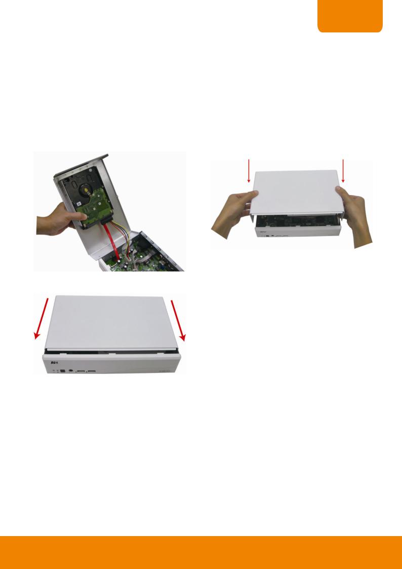
User can install 1 SATA hard disks inside the DVR unit.
Follow the illustrated instructions below to install the hard disk:
1. Loosen all screws(2 sides and rear side)
2.Push the cover backward and lift. The cover is a little bit tight, please be carefully the hands.
3.Turn the cover over and place the SATA hard disk (face 4. Screw the hard disk(both side) down) inside the HDD holder.
Place the hard disk face down and connector interface of hard disk in this direction.
12
CHAPTER 1
5. Hold the cover and connect the power cable and SATA 6. |
Then, turn the cover over carefully. Hold the cover |
cable to the hard disk. |
parallel with DVR unit and put the cover back to the DVR |
|
unit and be carefully the hard disk that inside the cover. |
7. Finally, Push the cover forward and secure the cover
13

1.4.1.2EH1116H-4+
i |
The external USB hard disk only supports on file backup. Please do not use the external USB hard disk for |
|
recording purpose. |
|
|
User can install 1 SATA hard disks inside the DVR unit.
Follow the illustrated instructions below to install the hard disk:
1. Loosen all screws (2 sides and rear side). Then, push |
2. Loosen the screws of holder in order to take out the hard |
the cover backward and lift. |
disk rack. |
3. Loosen all the screws of hard disk plate. |
4. The hard disk plate can be installed 2 hard disks only. |
|
User can choose the position and place the hard disk on |
|
it. |
|
[Note] Do Not install the hard disk at left position space on |
|
hard disk plate. |
Do Not install hard disk here
5.Turn the plate and hard disk over carefully and screw the hard disk on the plate. If hard disk cannot match to the screw hole, then, you may adjust the hard disk position to match the screw hole.
6.Then, place the hard disk plate within hard disk inside DVR unit and secure hard disk plate.
14

CHAPTER 1
7.Plug the SATA cable into SATA connector on the PC board if necessary. Then, connecting the power cable and SATA cable into hard disk.
When user remove power cable from hard disk, please DO NOT pull the power cable straight way. Please pull out the power cable by moving power connector to left and right side and slowly pull out the power cable from hard disk.
8. Screw the holder on the DVR unit. |
9. Finally, Push the cover forward and secure the cover. |
15
1.4.2 Connecting Devices
Pen drive and external hard disk must be FAT32 format.
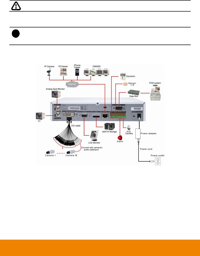
1.4.2.1 EH1116H-4 Nano/EH1116H-4 Nano+/EH1116H-4 Nano+-T
- All connected devices have its own power supply is necessary.
i - Up to 5 megapixels for one channel, and a total of 8 megapixels for all 4 IP camera channels in H.264/MPEG4/MJPEG format
- EH1116H-4 Nano/Nano+/Nano+-T support IP camera in first 4 channels.
The back panel of the DVR unit, user can connect up to 16 cameras in combination of analog and IP camera. The DVR unit also can connect 4 sensor devices, 1 alarm devices, and output video to a LCD monitor.
Follow the illustration below to make the connection:
16

CHAPTER 1
For backup recorded video, plugging the pen drive or external hard disk through USB port that are located at front panel of DVR unit, and then, use the bundled software enables user to transfer, playback and segment the video. Follow the illustration below to make the connection:
EH1116H-4 Nano
EH1116H-4 Nano+
EH1116H-4 Nano+-T
17

1.4.2.2EH1116H-4+
-All connected devices have its own power supply is necessary.
i- Up to 5 megapixels for one channel, and a total of 8 megapixels for all 4 IP camera channels in H.264/MPEG4/MJPEG format
-EH1116H-4+ supports IP camera in first 4 channels.
The back panel of the DVR unit, user can connect up to 16 cameras in combination of analog and IP camera. The DVR unit also can connect 4 sensor devices, 1 alarm devices, and output video to a LCD monitor.
Follow the illustration below to make the connection:
For backup recorded video, plugging the pen drive or external hard disk through USB port that are located at front panel of DVR unit, and then, use the bundled software enables user to transfer, playback and segment the video. Follow the illustration below to make the connection:
18

CHAPTER 1
1.5Audio, Sensor, Relay and RS485 pinhole allocation
The Sensor and Alarm enable you to connect 4 sensor inputs, 1 relay outputs and PTZ cameras. Just connect the external sensor, relay, and PTZ camera pin directly to the pinhole. Check the table below and locate which pinhole is assigned to sensor input and relay output.
1.5.1 Audio Out Pin Definition
|
|
Pin# |
|
Definition |
|
|
|
|
|
|
|
OUT |
|
Audio out signal |
|
|
|
|
|
1.5.2 |
Sensor Pin Definition |
|
|
|
|
|
|
|
|
|
|
Sensor Pin # |
|
Definition |
|
|
1 |
|
Sensor 1 signal |
|
|
|
|
|
|
|
2 |
|
Sensor 2 signal |
|
|
|
|
|
|
|
G |
|
Sensor ground |
|
|
|
|
|
|
|
3 |
|
Sensor 3 signal |
|
|
|
|
|
|
|
4 |
|
Sensor 4 signal |
|
|
G |
|
Sensor ground |
|
|
|
|
|
1.5.3 |
Relay Pin Definition |
|
|
|
|
|
|
|
|
|
|
Relay Pin # |
|
Definition |
|
|
|
|
|
|
|
C1 |
|
Relay Common 1 |
|
|
NO |
|
Relay Normal Open |
|
|
NC |
|
Relay Normal Close |
|
|
|
|
|
19

1.5.4 RS485 Pin Definition
When connect PTZ camera through RS485 interface, please refer to the following pin definition to connect the DVR and PTZ.
|
|
Pin # |
DVR site |
PTZ site |
|
|
|
TX+ |
RS485 TX+ signal |
RS485 RX+ signal |
|
|
|
|
|
|
|
|
|
TX- |
RS485 TXsignal |
RS485 RXsignal |
|
|
|
RX+ |
RS485 RX+ signal |
RS485 TX+ signal |
|
|
|
RX- |
RS485 RXsignal |
RS485 TXsignal |
|
|
|
|
|
|
|
|
|
|
|
||
i |
If user uses the 2 wires for the PTZ camera connection, please connect to the RS-485 TX+ and TXof |
||||
|
the DVR site. |
|
|
|
|
|
|
|
|
|
|
20
 Loading...