


EH6000H series
EH6108H+/EH6216H+
User’s Manual
V. 1.10.0
FCC NOTICE (Class B)
This device complies with Part 15 of the FCC Rules. Operation is subject to the following two conditions: (1) this device may not cause harmful interference, and (2) this device must accept any interference received, including interference that may cause undesired operation.
Federal Communications Commission Statement
NOTE- This equipment has been tested and found to comply with the limits for a Class B digital device, pursuant to Part 15 of the FCC Rules. These limits are designed to provide reasonable protection against harmful interference in a residential installation. This equipment generates uses and can radiate radio frequency energy and, if not installed and used in accordance with the instructions, may cause harmful interference to radio communications. However, there is no guarantee that interference will not occur in a particular installation. If this equipment does cause harmful interference to radio or television reception, which can be determined by tuning the equipment off and on, the user is encouraged to try to correct the interference by one or more of the following measures:
Reorient or relocate the receiving antenna.
Increase the separation between the equipment and receiver.
Connect the equipment into an outlet on a circuit different from that to which the receiver is connected.
Consult the dealer or an experienced radio/television technician for help.
European Community Compliance Statement (Class B)
This product is herewith confirmed to comply with the requirements set out in the Council Directives on the Approximation of the laws of the Member States relating to Electromagnetic Compatibility Directive 2004/108/EC.
DISCLAIMER
No warranty or representation, either expressed or implied, is made with respect to the contents of this documentation, its quality, performance, merchantability, or fitness for a particular purpose. Information presented in this documentation has been carefully checked for reliability; however, no responsibility is assumed for inaccuracies. The information contained in this documentation is subject to change without notice.
In no event will AVer Information Inc. be liable for direct, indirect, special, incidental, or consequential damages arising out of the use or inability to use this product or documentation, even if advised of the possibility of such damages.
TRADEMARKS
“AVer” is a trademark owned by AVer Information Inc. Other trademarks used herein for description purpose only belong to each of their companies.
COPYRIGHT
© 2012 AVer Information Inc. All rights reserved.
No part of this document may be reproduced or transmitted in any form, or by any means without the prior written permission of AVer Information Inc. AVer Information Inc. reserves the rights to modify its models, including their characteristics, specifications, accessories and any other information stated herein without notice. The official printout of any information shall prevail should there be any discrepancy between the information contained herein and the information contained in that printout.
The mark of Crossed-out wheeled bin indicates that this product must not be disposed of with your other household waste. Instead, you need to dispose of the waste equipment by handing it over to a designated collection point for the recycling of waste electrical and electronic equipment. For more information about where to drop off your waste equipment for recycling, please contact your household waste disposal service or the shop where you purchased the product.
Battery Safety Information
-Store the batteries in a cool dry place.
-Do not dispose of used batteries in domestic waste. Dispose of batteries at special collection points or return to point of sale if applies.
-Remove the batteries during long periods of non-use. Always remove exhausted batteries from the remote control. Battery leakage and corrosion can damage this remote control, dispose of batteries safely.
-Do not mix old and new batteries.
-Do not mix different types of batteries: alkaline, standard (carbon-zinc) or rechargeable (nickel-cadmium).
-Do not dispose of batteries in a fire. The batteries may explode or leak.
-Never short circuit the battery terminals.
WARNING
TO REDUCE RISK OF FIRE OR ELECTRIC SHOCK, DO NOT EXPOSE THIS APPLIANCE TO RAIN OR MOISTURE
CAUTION
IF THERE IS ANY DAMAGE, SHORTAGE OR INAPPROPRIATE ITEM IN THE PACKAGE, PLEASE CONTACT WITH YOUR LOCAL DEALER. WARRANTY VOID FOR ANY UNAUTHORIZED PRODUCT MODIFICATION
NOTICE
-INFORMATION IN THIS DOCUMENT IS SUBJECT TO CHANGE WITHOUT NOTICE.
-THE INFORMATION CONTAINED HEREIN IS TO BE CONSIDERED FOR REFERENCE ONLY.
Manual Updates
Following are listed the new functions for the version X9.03.24.00.07a and above of EH6000H series surveillance software.
Function |
Description |
Plug and Play |
DVR system supports AVer IP camera series to connect to DVR system without |
(Camera Setting) |
any configuration; user can use “search device” function to find the AVer series IP |
|
camera on your LAN network. |
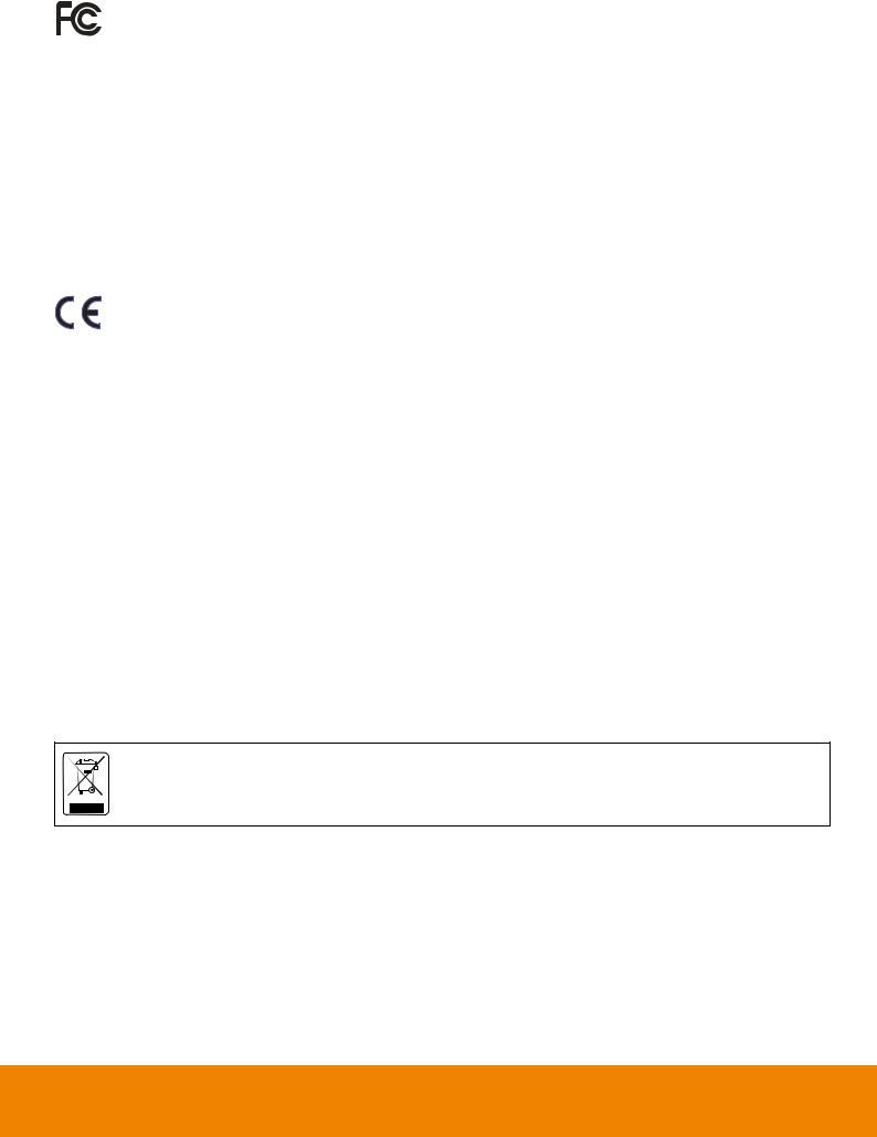
Active IP |
Allows user to configure the AVer IP camera series on DVR system; user doesn’t |
(Camera Setting) |
need to connect to IP camera on PC to configure the IP camera setting. |
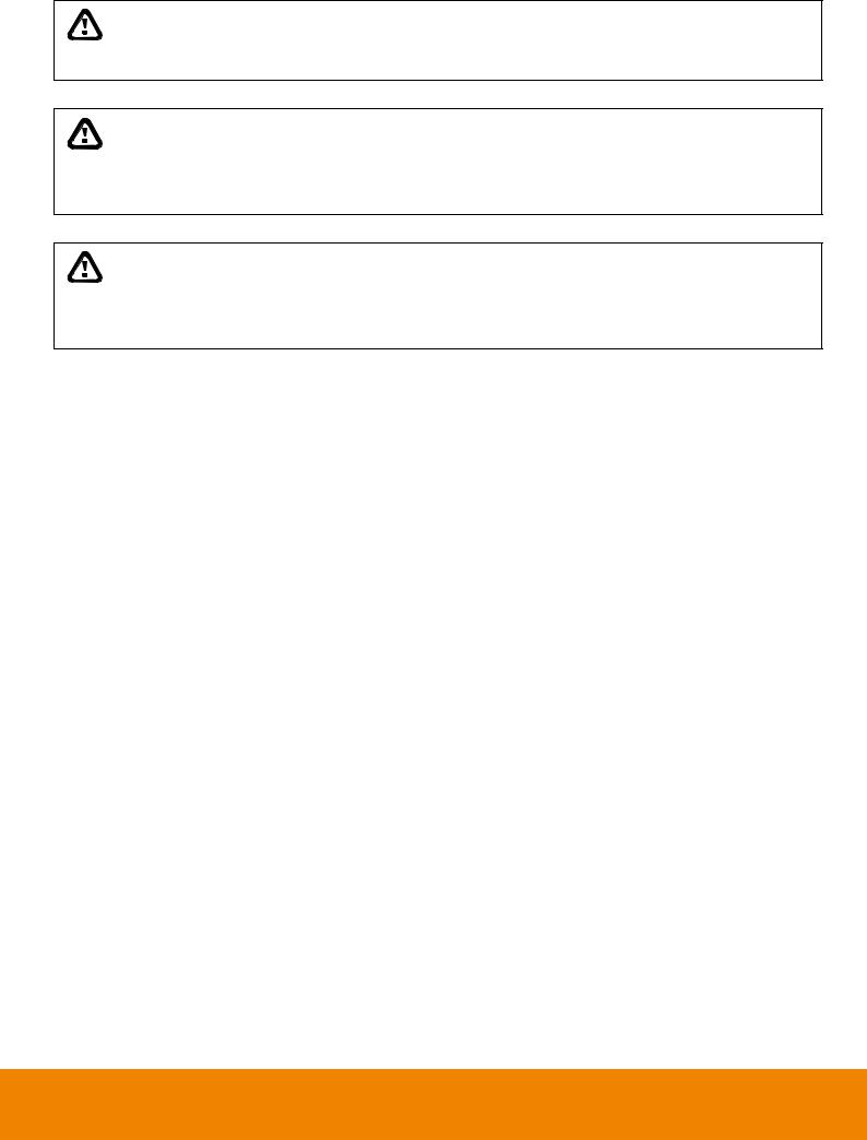
Logout |
Allows user to set a system idle time to log out DVR system automatically. The idle |
|
time period rage is 1 to 60 minutes. |
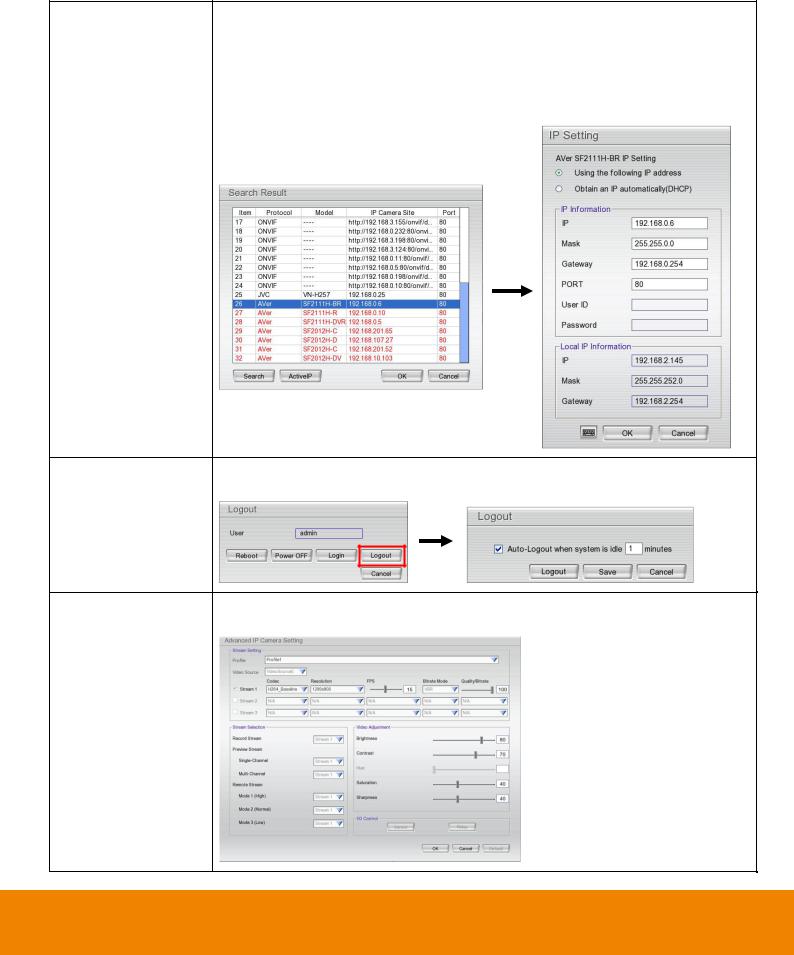
ONVIF IP camera The DVR system supports IP camera’s detail setting on the IP camera is using advanced setting ONVIF protocol to connect it.
(Camera Setting)
Function |
Description |
|||||
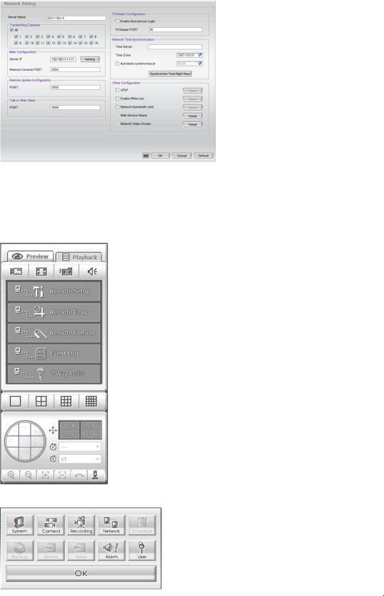
Two way audio port |
Allows user to modify the port number for two-way audio. |
|||||
is configurable |
|
|
|
|
|
|
(Network Setting) |
|
|
|
|
|
|
|
|
|
|
|
|
|
|
|
|
|
|
|
|
|
|
|
|
|
|
|
Provides local |
The DVR system will transmit the DVR local information (IP, name of DVR, CPU |
|||||
information to CMS |
usage, free HDD capacity, recording status, video loss status, and estimate |
|||||
server |
recording day…etc) to CMS server. User can check the information that provides |
|||||
|
by DVR system at DVR Status on CMS server. |
|||||
Two-way audio on |
The two-way audio function is available on PCViewer. |
|||||
PCViewer |
|
|
|
|
|
|
|
|
|
|
|
|
|
|
|
|
|
|
|
|
|
|
|
|
|
|
|
User setting function |
The user setting function is available on Remote Setup. |
|||||
(Remote setup) |
|
|
|
|
|
|
|
|
|
|
|
|
|
|
|
|
|
|
|
|
|
|
|
|
|
|
|

Table of Contents
Manual Updates............................................................................................................................ |
4 |
|||
Chapter 1 Introduction.............................................................................................................. |
1 |
|||
1.1 |
Package Content................................................................................................................... |
1 |
||
|
1.1.1 |
EH6108H+ ..................................................................................................................... |
1 |
|
|
1.1.2 |
EH6216H+ ..................................................................................................................... |
2 |
|
|
1.1.3 |
Optional Accessories ..................................................................................................... |
2 |
|
1.2 |
Front Panel............................................................................................................................ |
3 |
||
|
1.2.1 EH6108H+/EH6216H+.................................................................................................... |
3 |
||
|
1.2.1.1 To Cut and Save the Portion of the Recorded Video........................................... |
6 |
||
1.3 |
Back Panel |
............................................................................................................................ |
7 |
|
|
1.3.1 |
EH6108H+ (HDMI supported)........................................................................................ |
7 |
|
|
1.3.2 |
EH6108H+ (None HDMI) ............................................................................................... |
8 |
|
|
1.3.3 |
EH6216H+ (HDMI supported)........................................................................................ |
9 |
|
|
1.3.4 |
EH6216H+ (None HDMI) ............................................................................................. |
10 |
|
1.4 |
Setting Up the DVR Unit...................................................................................................... |
11 |
||
|
1.4.1 Installing the Hard Disks ................................................................................................ |
11 |
||
|
1.4.2 Connecting Devices ....................................................................................................... |
14 |
||
|
1.4.2.1 |
EH6108H+ ........................................................................................................ |
14 |
|
|
1.4.2.2 |
EH6216H+ ........................................................................................................ |
16 |
|
|
1.4.3 Sensor, Relay and RS485 pinhole allocation ................................................................. |
18 |
||
|
1.4.3.1 |
Sensor Pin Definition......................................................................................... |
18 |
|
|
1.4.3.2 |
Relay Pin Definition........................................................................................... |
18 |
|
|
1.4.3.3 |
RS485 Pin Definition ......................................................................................... |
19 |
|
1.5 |
Familiarizing the Remote Controller Buttons ....................................................................... |
20 |
||
1.6 |
Upgrading the DVR System Firmware ................................................................................ |
23 |
||
|
1.6.1 |
USB Recovery ............................................................................................................. |
23 |
|
|
1.6.2 |
Local UI Upgrading ...................................................................................................... |
26 |
|
|
1.6.3 |
Remote ISP Upgrading................................................................................................ |
29 |
|
Chapter 2 Using the DVR Software .................................................................................... |
32 |
|||
2.1 |
The Way to Operate DVR.................................................................................................... |
32 |
||
|
2.1.1 First Time Using the DVR Unit ..................................................................................... |
32 |
||
|
2.1.2 Using the Virtual Keyboard .......................................................................................... |
33 |
||
2.2 |
Familiarizing the Buttons in Preview Mode.......................................................................... |
34 |
||
|
|
|
|
|

|
2.2.1 To Setup DVR System Logout Time ............................................................................ |
37 |
|
2.2.2 Setting Up and Using the Emap .................................................................................. |
38 |
|
2.2.3 Familiarizing the Buttons in PTZ Camera Controller.................................................... |
39 |
|
2.2.3.1 Setup the Analog PTZ Camera ....................................................................... |
40 |
|
2.2.3.2 Setup the IP PTZ Camera ............................................................................... |
41 |
|
2.2.4 Using Event Log Viewer .............................................................................................. |
42 |
|
2.2.4.1 Using POSViewer............................................................................................ |
43 |
2.3 |
Familiarizing the Buttons in Playback Mode ........................................................................ |
44 |
|
2.3.1 To Cut and Save the Portion of the Recorded Video ................................................... |
47 |
|
2.3.2 To Bookmark a Video Section...................................................................................... |
47 |
|
2.3.3 To Search Using Visual Search ................................................................................... |
48 |
|
2.3.4 To Search Using the Event Search .............................................................................. |
50 |
Chapter 3 Customizing the DVR System.......................................................................... |
51 |
|
3.1 |
System Setup ...................................................................................................................... |
51 |
3.2 |
Camera Setup ..................................................................................................................... |
57 |
|
3.2.1 To Setup IP Camera(Fixed Mode) ............................................................................... |
57 |
|
3.2.2 To Setup IP Camera(Flexible Mode)............................................................................ |
61 |
|
3.2.2.1 Using Search Device to Connect IP Camera .................................................... |
67 |
|
3.2.3 To Setup Analog Camera............................................................................................. |
69 |
|
3.2.4 To Setup Camera from the Remote DVR(Fixed Mode)................................................ |
70 |
|
3.2.5 To Setup Camera from the Remote DVR(Flexible Mode) ............................................ |
71 |
3.3 |
Recording Setup.................................................................................................................. |
74 |
|
3.3.1 Setup IP Camera Record Setting................................................................................. |
74 |
|
3.3.2 Setup Analog Camera Record Setting ........................................................................... |
75 |
3.4 |
Network Setup..................................................................................................................... |
78 |
3.5 |
Schedule Setting ................................................................................................................. |
82 |
3.6 |
Backup Setup ...................................................................................................................... |
83 |
|
3.6.1 Using QPlayer to Playback Backup Video ................................................................... |
85 |
|
3.6.2 To Cut and Save the Portion of the Recorded Video ................................................... |
87 |
|
3.6.3 To Search Using the Visual Search ............................................................................. |
88 |
|
3.6.4 To Search Using the Event Search.............................................................................. |
88 |
|
3.6.5 To Search Using the Intelligent Search........................................................................ |
89 |
3.7 |
Sensor Setting..................................................................................................................... |
90 |
3.8 |
Relay Setting ....................................................................................................................... |
91 |
3.9 |
Alarm Setting....................................................................................................................... |
92 |
3.10 |
User Setup .......................................................................................................................... |
99 |
Chapter 4 Using the Remote Programs .......................................................................... |
101 |
||
4.1 Familiarizing the Buttons in PCViewer .............................................................................. |
102 |
||
4.1.1 |
PCViewer Screen ...................................................................................................... |
102 |
|
4.1.2 |
PCViewer Control Panel ............................................................................................ |
104 |
|
4.1.3 Playback Mode Control Panel ................................................................................... |
106 |
||
4.1.4 To Setup Remote System Setting .............................................................................. |
108 |
||
4.1.4.1 |
System Setting ................................................................................................ |
108 |
|
4.1.4.2 |
Camera Setting ............................................................................................... |
110 |
|
4.1.4.3 |
Record Setting ................................................................................................ |
114 |
|
4.1.4.4 |
Network Setting............................................................................................... |
118 |
|
4.1.4.5 |
Alarm Setting .................................................................................................. |
120 |
|
4.1.4.6 |
User Setting .................................................................................................... |
125 |
|
4.2 Familiarizing the Buttons in Remote Console.................................................................... |
127 |
||
4.2.1 To Setup Remote Console Setting............................................................................. |
129 |
||
4.2.2 Familiarizing the Buttons in PTZ Camera Controller.................................................. |
130 |
||
4.3 Using the Remote Playback .............................................................................................. |
131 |
||
4.3.1 Familiarizing the Buttons in Local Playback............................................................... |
133 |
||
4.3.1.1 To Cut and Save the Wanted Portion of the Recorded Video.......................... |
135 |
||
4.3.1.2 To Search Using the Visual Search................................................................. |
136 |
||
4.3.1.3 To Search Using the Intelligent Search ........................................................... |
136 |
||
4.3.2 Familiarizing the Buttons in RealTime Playback ........................................................ |
137 |
||
4.3.3 Familiarizing the Buttons in Download and Playback ................................................ |
139 |
||
Chapter 5 Using the Web Tools ......................................................................................... |
141 |
|
5.1 |
Remote Setup ................................................................................................................... |
141 |
|
5.1.1 To Add DVR server .................................................................................................... |
141 |
|
5.1.2 To Setup Remote System Setting .............................................................................. |
142 |
5.2 |
Remote Backup................................................................................................................. |
143 |
|
5.2.1 To back up the recorded data from the DVR server................................................... |
143 |
Appendix A Registering Domain Name ..................................................................................... |
146 |
|
Appendix B Network Service Port ............................................................................................. |
148 |
|
|
|
|
|
|
|
CHAPTER 1
Chapter 1 Introduction
1.1Package Content
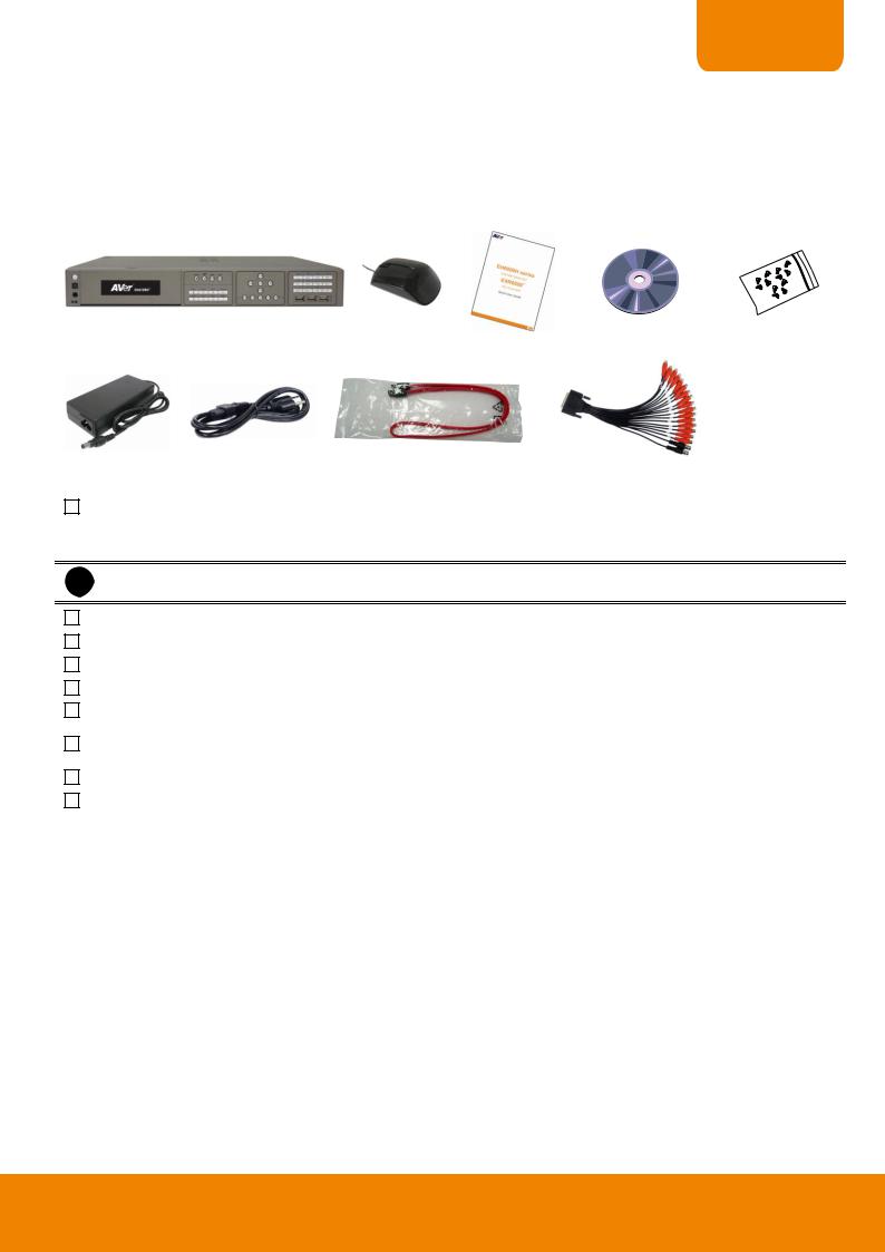
1.1.1 EH6108H+
(1) |
(2) |
(4) |
(5) |
|
|
||
|
|
(3) |
|
(6) |
(7) |
(8) |
|
||
|
|
(9) |
(1) DVR unit
-EH6108+ with HDMI interface
-EH6108H+ w/o HDMI interface
iEH6108H+ supports DVD-ROM or HDD tray that depends on user has purchased.
(2) USB optical mouse
(3) Quick User Guide
(4) Software CD (User Manual included)
(5) Screws for HDD installation
(6) Power adaptor
(7) Power Cord
* The power cord varies depending on the standard power outlet of the country where it is sold.
(8) SATA cables
(9) Audio cable(Red cable: 8CH audio in/Black cable: 1CH Spot out &1CH TV out)
1
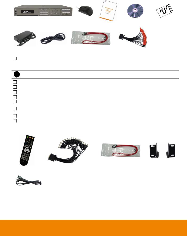
1.1.2 EH6216H+
(1) |
(2) |
(4) |
(5) |
|
|
||
|
|
(3) |
|
(6) |
(7) |
(8) |
|
||
|
|
(9) |
(2) DVR unit
-EH6216+ with HDMI interface
-EH6216H+ w/o HDMI interface
iEH6216H+ supports DVD-ROM or HDD tray that depends on user has purchased.
(2) USB optical mouse
(3) Quick User Guide
(4) Software CD (User Manual included)
(5) Screws for HDD installation
(6) Power adaptor
(7) Power Cord
* The power cord varies depending on the standard power outlet of the country where it is sold.
(8) SATA cables
(9) Audio cable(Red cable: 16CH audio in/Black cable: 1CH Spot out &1CH TV out)
1.1.3 Optional Accessories
SATA cable for hard disk installation |
Rack ears |
Remote controller |
16CH Loop out cable |
|
IR extended cable
2
CHAPTER 1
1.2Front Panel
1.2.1 EH6108H+/EH6216H+
|
Name |
|
Function |
|
|
|
|
|
|||
|
|
|
|
- Power indicator (left): System power status indicators. Lights when the system is |
|
(1) |
System indicator |
|
running. |
||
|
|
|
|
- Record indicator (right): When DVR system is recording, the light will keep flashing. |
|
(2) |
IR Sensor port |
|
For extended IR sensor cable connection(optional) |
||
|
|
|
|
||
(3) |
IR Sensor |
|
Receive signal from the remote controller to operate the DVR unit |
||
|
|
|
|
||
(4) |
Power |
|
Power ON/OFF DVR unit |
||
(5)DVD-ROM/HDD Tray
-DVD-ROM: To backup the recorded file to DVD± R/DVD± RW disk
-HDD Tray: To install one hard disk.
-CD-R/RW is not supported.
i- EH6108H+ and EH6216H+ support DVD-ROM or HDD tray that depends on user has purchased.
(6) |
|
To start recording video |
|
||
|
|
|
(7) |
|
To reset alarm status |
|
|
|
(8) |
|
Switch to playback mode or preview mode |
|
|
|
(9) |
|
Call out system setup menu on preview mode |
|
|
Move to left direction on cursor control |
|
|
|
|
|
To move PTZ camera lens to left in PTZ mode |
|
|
|
|
|
Move to right direction on cursor control |
|
|
|
|
|
To move PTZ camera lens to right in PTZ mode |
|
|
|
(10) Control Buttons |
Move to up direction on cursor control |
|
|
||
|
|
To move PTZ camera lens to up |
|
|
|
|
|
Move to down direction on cursor control |
|
|
|
|
|
To move PTZ camera lens to down |
|
|
|
|
|
Confirm or make a selection |
|
|
|
3
|
Name |
|
Function |
|
|
|
|
||
|
|
|
|
|
|
|
|
|
|
-Channel camera selection number in playback and preview mode. For the channel over 10, press  , then press
  ~
~ 
- |
Press |
|
|
, and then press |
|
|
can switch |
||||
|
|
|
|
||||||||
|
|
|
|
|
|
|
|
|
|
|
|
~ |
|
|
to character mode. |
|
|
|
|||||
|
|
|
|
|
|||||||
|
|
|
|
|
|||||||
|
- |
Press |
|
|
button can switch to different screen |
||||||
|
|
|
|
||||||||
|
|||||||||||
|
|
|
|
|
|
|
|
|
|
|
|
|
|
|
display modes ( |
|
|
~ |
|
|
). |
|
|
|
|
|
|
|
|
|
|
||||
|
|
|
|
|
|
|
|
|
|
|
|
-Press 


 and number button, to set the preset position in the PTZ mode.
-Switch to character mode.
|
|
|
|
|
- Press |
|
to switch to FN mode (The word “FN” |
||||||
|
|
|
|
|
|
|
|
|
|
|
|
|
|
|
|
|
|
|
is displayed in the left bottom corner on screen). Then, |
||||||||
|
|
|
|
|
press |
|
|
to enter EN mode (The word “EN” is |
|||||
|
|
|
|
|
|
||||||||
|
|
|
|
|
|
|
|
|
|
|
|
|
|
|
|
|
|
|
displayed in the left bottom corner on screen). User can |
||||||||
(11) Number buttons |
|
|
|
|
press the character button and press rapidly to find the |
||||||||
|
|
|
|
character that wants to enter. |
|||||||||
|
|
|
|
|
|||||||||
|
|
|
|
|
|
|
|
|
|
|
|
: backward/delete button |
|
|
|
|
|
|
|
|
|
|
|
|
|
||
|
|
|
|
|
|
|
|
|
|
|
|
: abcABC |
|
|
|
|
|
|
|
|
|
|
|
|
|
||
|
|
|
|
|
|
|
|
|
|
|
|
||
|
|
|
|
|
|
|
|
|
|
|
|
||
|
|
|
|
|
|
|
|
|
|
|
|
||
|
|
+ |
|
|
|
|
|
|
|
|
|
: edfDEF |
|
|
|
|
|
|
|
|
|
|
|
|
|||
|
|
|
|
|
|
|
|
|
|
|
|||
|
|
|
|
|
|
|
|
|
|
|
|||
|
|
|
|
|
|
|
|
|
|
|
: ghiGHI |
||
|
|
|
|
|
|
|
|
|
|
|
|||
|
|
|
|
|
|
|
|
|
|
|
|
||
|
|
|
|
|
|
|
|
|
|
|
|
||
|
|
|
|
|
|
|
|
|
|
|
|
||
|
|
|
|
|
|
|
|
|
|
|
|
: jklJKL |
|
|
|
|
|
|
|
|
|
|
|
|
|
||
|
|
|
|
|
|
|
|
|
|
|
|
||
|
|
|
|
|
|
|
|
|
|
|
|
: mnoMNO |
|
|
|
|
|
|
|
|
|
|
|
|
|
||
|
|
|
|
|
|
|
|
|
|
|
|
||
|
|
|
|
|
|
|
|
|
|
|
|
: pqrsPQRS |
|
|
|
|
|
|
|
|
|
|
|
|
|
||
|
|
|
|
|
|
|
|
|
|
|
|
||
|
|
|
|
|
|
|
|
|
|
|
|
: tuvTUV |
|
|
|
|
|
|
|
|
|
|
|
|
|
||
|
|
|
|
|
|
|
|
|
|
|
|
||
|
|
|
|
|
|
|
|
|
|
|
|
: wxyzWXYZ |
|
|
|
|
|
|
|
|
|
|
|
|
|
||
|
|
|
|
|
|
|
|
|
|
|
|
||
|
|
|
|
|
|
|
|
|
|
|
|
: space button |
|
|
|
|
|
|
|
|
|
|
|
|
|
||
|
|
|
|
|
|
|
|
|
|
|
|
||
|
|
|
|
|
|
|
|
|
|
|
|
|
|
|
|
|
|
|
|
|
|
|
|
|
|
|
|
4
CHAPTER 1
 Name
Name
(12)
 Function
A functional key for multiple system control. Press |
|
to switch to FN mode (The |
||||||||||||||||
word “FN” will show up in the left bottom corner on screen). Press |
|
button again |
||||||||||||||||
|
|
|
|
|
|
|
|
|
|
|
|
|
|
|
|
|
||
to exit FN mode (The “X” will show up in the left bottom corner on screen). |
|
|||||||||||||||||
|
|
|
|
|
|
|
|
|
|
|
|
|
|
: Switch to single screen display mode |
|
|||
|
|
|
+ |
|
|
|
|
|
|
|
|
|
|
|
||||
|
|
|
|
|
|
|
|
|
|
|||||||||
|
|
|
|
|
|
|
|
|
|
|
|
|
|
: Switch to QUAD display mode |
|
|
|
|
|
|
|
|
|
|
|
|
|
|
|
|
|
|
|
|
|
||
|
|
|
|
|
|
|
|
|
|
|
|
|
|
|
|
|
||
|
|
|
+ |
|
|
|
|
|
|
|
|
|
|
|
|
|
||
|
|
|
|
|
|
|
|
|
|
|
|
|
|
|
|
|||
|
|
|
|
|
|
|
|
|
|
|
|
|
|
: Switch to 9 spilt screen display mode |
|
|||
|
|
|
|
|
|
|
|
|
|
|
|
|
|
|
||||
|
|
|
|
|
|
|
|
|
|
|
|
|
|
|
||||
|
|
|
+ |
|
|
|
|
|
|
|
|
|
|
|
||||
|
|
|
|
|
|
|
|
|
|
|||||||||
|
|
|
|
|
|
|
|
|
|
|
|
|
|
: Switch to 16 split screen display mode |
|
|||
|
|
|
|
|
|
|
|
|
|
|
|
|
|
|
||||
|
|
|
|
|
|
|
|
|
|
|
|
|
|
|
||||
|
|
|
+ |
|
|
|
|
|
|
|
|
|
|
|
||||
|
|
|
|
|
|
|
|
|
|
|||||||||
|
|
|
|
|
|
|
|
|
|
|
|
|
|
: Switch to one single and 8 spilt screen display mode |
||||
|
|
|
|
|
|
|
|
|
|
|
|
|
|
|||||
|
|
|
+ |
|
|
|
|
|
|
|
|
|
|
|||||
|
|
|
|
|
|
|
|
|
||||||||||
|
|
|
|
|
|
|
|
|
|
|
|
|
|
: Switch to one single and 13 spilt screen display mode |
||||
|
|
|
|
|
|
|
|
|
|
|
|
|
|
|||||
|
|
|
|
|
|
|
|
|
|
|
|
|
||||||
|
|
|
+ |
|
|
|
|
|
|
|
|
|
|
|||||
|
|
|
|
|
|
|
|
|
|
|||||||||
|
|
|
|
|
|
|
|
|
|
|
|
|
|
: Enable/disable auto scan |
|
|
|
|
|
|
|
|
|
|
|
|
|
|
|
|
|
|
|
|
|||
|
|
|
|
|
|
|
|
|
|
|
|
|
|
|
|
|||
|
|
|
+ |
|
|
|
|
|
|
|
|
|
|
|
|
|
||
|
|
|
|
|
|
|
|
|
|
|
|
|
|
|||||
|
|
|
|
|
|
|
|
|
|
|
|
|
|
: Switch to full screen mode |
|
|
|
|
|
|
|
|
|
|
|
|
|
|
|
|
|
|
|
|
|||
|
|
|
|
|
|
|
|
|
|
|
|
|
|
|
|
|||
|
|
|
+ |
|
|
|
|
|
|
|
|
|
|
|
|
|
||
|
|
|
|
|
|
|
|
|
|
|
|
|
|
|
||||
|
|
|
|
|
|
|
|
|
|
|
|
|
|
: Switch to characters mode |
|
|
|
|
|
|
|
|
|
|
|
|
|
|
|
|
|
|
|
|
|||
|
|
|
|
|
|
|
|
|
|
|
|
|
|
|
||||
|
|
+ |
|
|
|
|
|
|
|
|
|
|
|
|
|
|||
|
|
|
|
|
|
|
|
|
|
|
|
|
|
|
|
|||
|
|
|
|
|
|
|
|
|
|
|
|
|
|
|
|
|
|
|
|
|
|
|
|
|
|
|
|
|
|
|
|
|
|
|
|
|
|
3 x USB 2.0 ports for connecting USB device, ex: USB pen drive, external hard disk, mouse…and so on.
(13) |
USB 2.0 port |
|
|
i |
|
|
The USB backup device must be in FAT32 format. |
||||||
|
|
|
|
|
|
||||||||
|
|
|
|
|
|
|
|
|
|
|
|
|
|
|
|
|
|
|
|
|
|
|
|
|
|
|
|
|
|
|
|
|
|
|
|
To playback video at faster speed |
|||||
|
|
|
|
|
|
|
|
|
|
|
|
|
|
(14) |
Playback buttons |
|
|
|
|
|
|
To start playback |
|
||||
|
|
|
|
|
|
To pause playback |
|||||||
|
|
|
|
|
|
|
|
||||||
|
|
|
|
|
|
|
|
|
|
|
|
|
|
|
|
|
|
|
|
|
|
To rewind the recorded video |
|||||
|
|
|
|
|
|
|
|
|
|
||||
(15) |
|
|
Set a video segment to playback repeat (see Chapter 1.2.1.1). |
||||||||||
|
|
|
|
|
|
|
|
|
|||||
(16) |
|
|
To backup recorded video file to USB storage device(pen drive or external hard disk) and |
||||||||||
|
|
DVD-ROM. |
|||||||||||
|
|
|
|||||||||||
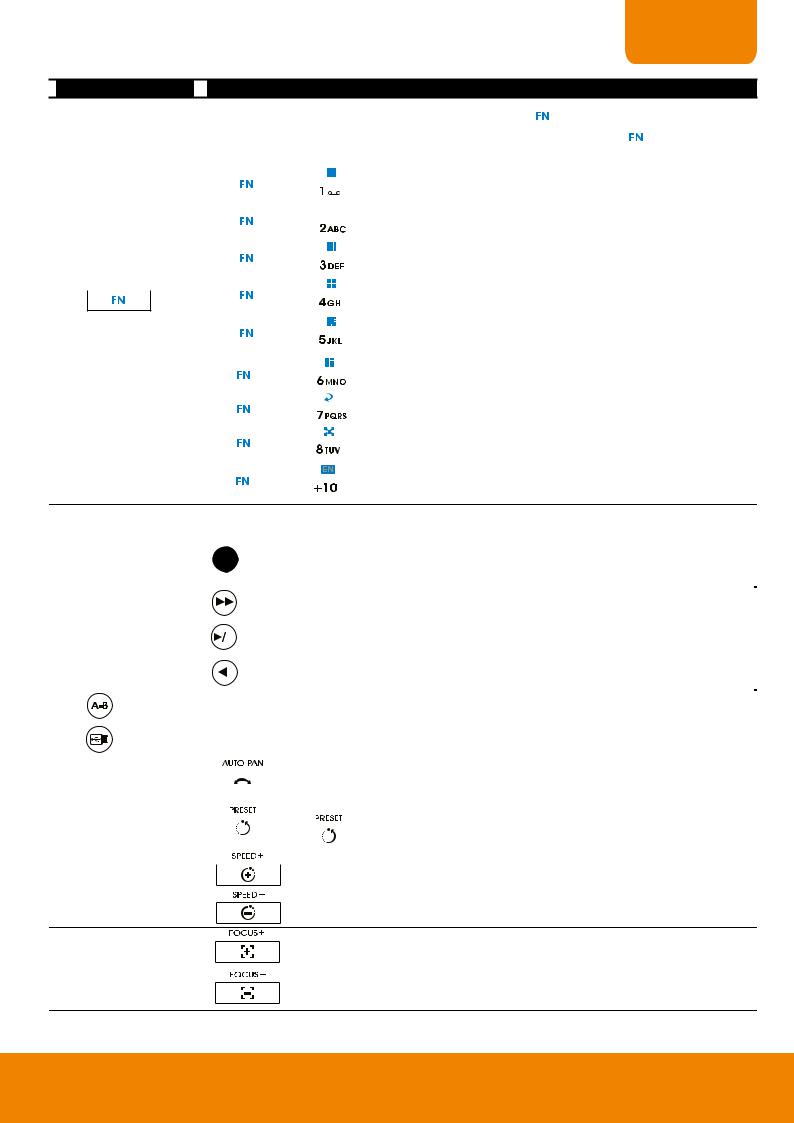
(17) Auto Pan |
|
|
|
|
|
|
|
|
|
To enable auto pan function |
|||
|
|
|
|
|
|
|
|
|
|||||
|
|
|
|
|
|
|
|
|
|
|
|
|
|
|
|
|
|
|
|
|
|
|
|
|
|||
|
|
|
|
|
|
|
|
|
|
Adjust the PTZ lens to the position that user wants. And then, press |
|||
(18) |
Preset |
|
|
|
|
|
|
|
|
|
|
with number button to setup the PTZ camera preset position. |
|
|
|
|
|
|
|
|
|
|
|
||||
|
|
|
|
|
|
|
|
|
|
|
|
||
|
|
|
|
|
|
|
|
|
|
|
|
|
|
|
|
|
|
|
|
|
|
|
|
|
|
||
|
|
|
|
|
|
|
|
|
|
|
To speed up movement of PTZ camera lens |
||
|
|
|
|
|
|
|
|
|
|
|
|||
(19) Speed + / Speed -
To speed down movement of PTZ camera lens
To focus in PTZ camera lens
(20) Focus + / Focus -
To focus out PTZ camera lens
5

|
Name |
|
Function |
|
|
|
|
||
|
|
|
|
|
|
|
|
|
|
To zoom in view of PTZ camera lens
(21) Zoom + / Zoom -
To zoom out view of PTZ camera lens
1.2.1.1To Cut and Save the Portion of the Recorded Video
1.Use the Playback Control buttons or drag the bar on the playback progress bar and pause on where you want to start the cut. Then, click  to set the begin mark.
2.Use the Playback Control buttons or drag the bar on the playback progress bar and pause on where you want to end the cut. Then, click  to set the end mark. To cancel segmentation, click
  button again.
3.Click Export button and select Output Video Clip to save the wanted portion. User can rename the File name. Mark “Include Player when backup” option to include a Qplayer application in backup file for palyback backup video clip later on. Mark “Add watermark when backup” option to have watermark protection on backup file and user can have watermark exam on Qplayer application.
4.Click Save to save the video clip. User should see a folder named “backup” on your USB storage device.
5.To playback the backup video clip, using Qplayer application that is included in backup folder.
6
CHAPTER 1
1.3Back Panel
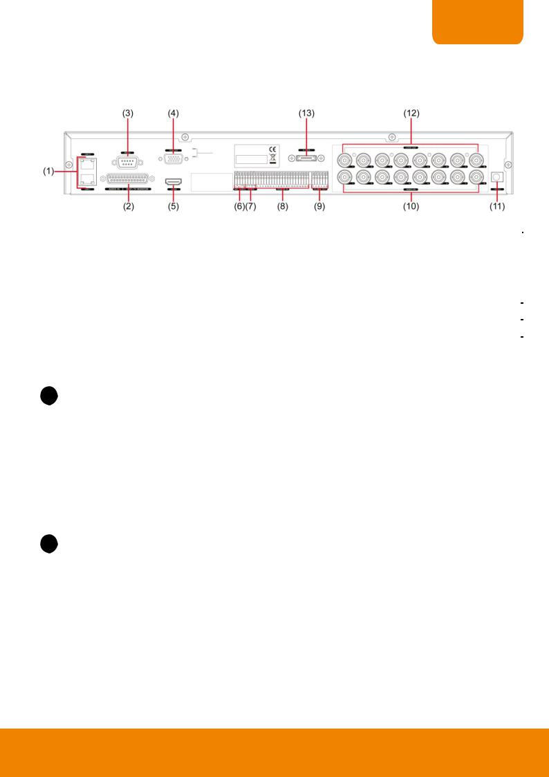
1.3.1 EH6108H+ (HDMI supported)
|
Name |
|
Function |
|
|
|
|
|
|
|
|||
(1) |
LAN 1/LAN 2 port |
|
For Gigabit Ethernet connection |
|||
|
|
|
|
|
|
|
(2) |
Audio IN/SPOT/TV |
|
- Audio input (red connector): 8 channels(stick 1~8 on cable only). To connect with |
|||
|
camera’s audio cable. |
|||||
|
|
Monitor |
|
|||
|
|
|
- Spot Monitor (sticker 2 on cable): 1 spot output. Outputs the analog video signals to |
|||
|
|
|
|
|||
|
|
|
|
Spot monitor when receive the alarm events. |
||
|
|
|
|
- TV output (sticker 1 on cable): 1 TV output. Output the video signal to a TV. |
|
|
(3) |
VGA Out |
|
Output the video signal to a CRT or LCD monitor |
|||
|
|
|
|
|
||
(4) |
RS232 port |
|
For POS device connection |
|||
|
|
|
|
|
||
(5) |
HDMI port |
|
Output the video signal to TV/HDMI monitor. |
|||
|
|
|
|
|
||
(6) |
MIC/Audio |
|
MIC: To connect the microphone. |
|||
|
|
|
|
Audio: For audio output device connection, such as speaker. |
||
|
|
|
|
|||
|
i |
The audio input and output device has its own power supply is necessary. |
||||
|
|
|
|
|||
|
|
|
|
|
||
(7) |
RS485 |
|
For analog PTZ camera connection (also see Chapter 1.4.3). |
|||
|
|
|
|
|
||
(8) |
Sensor In |
|
Support up to 16 sensor devices |
|||
|
|
|
|
|
||
(9) |
Relay Out |
|
Support 4 relay devices (Relay: 1A @ 125V AC/30V DC). |
|||
|
|
|
|
|
||
(10) |
Video Loop Out |
|
Output the analog video signal to a CCTV monitor. |
|||
|
|
|
|
|
||
(11) |
19V DC connector |
|
Connect the power adaptor into this port. |
|||
|
|
|
|
|
||
(12) |
CH1~ 08 |
|
Input the video camera signal and display it on channel 1~ 08. |
|||
|
|
|
|
|
||
(13) |
eSATA port |
|
For connecting with HDD or RAID. |
|||
|
|
|
|
|||
|
i |
When connecting eSATA device, please make sure the DVR has installed hard disk to reduce abnormal |
||||
|
|
situation occurs. |
|
|
|
|
|
|
|
|
|
|
|
|
|
|
|
|
|
|
7
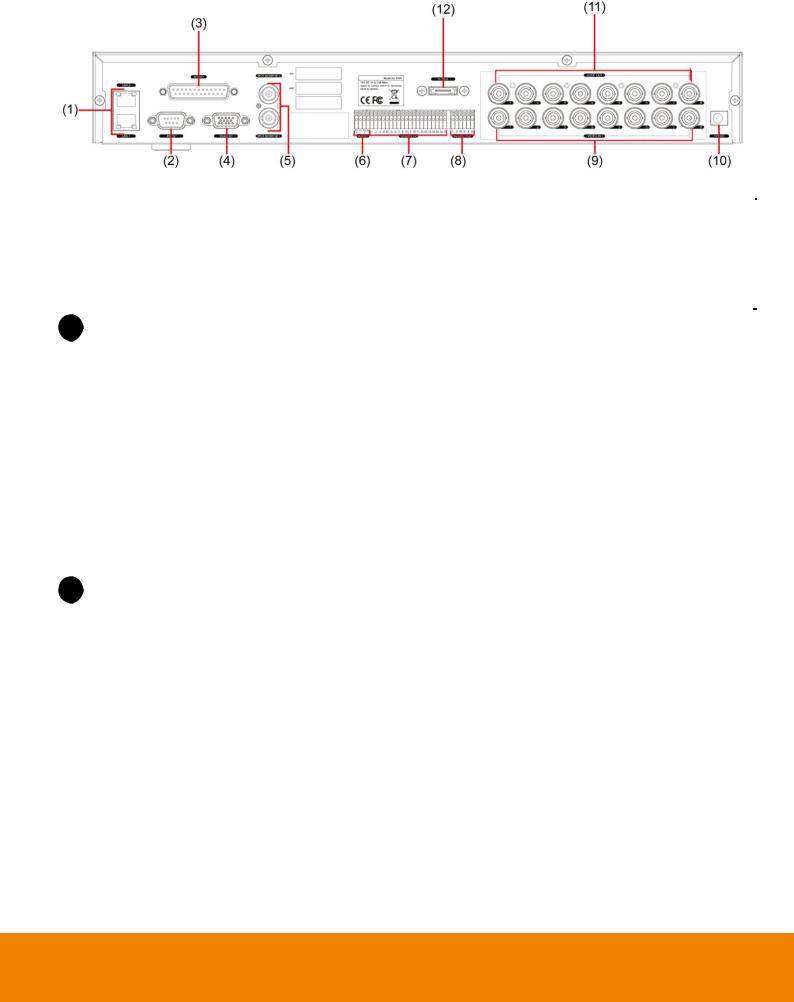
1.3.2 EH6108H+ (None HDMI)
|
Name |
|
Function |
|
|
|
|
|
|
|
|||
(14) |
LAN 1/LAN 2 port |
|
For Gigabit Ethernet connection |
|||
|
|
|
|
|
||
(15) |
RS232 port |
|
For POS device connection |
|||
|
|
|
|
|
|
|
(16) |
Audio port |
|
Input/output audio signal to audio input/output device. |
|||
|
- Audio input: 8 channels |
|||||
|
|
|
|
|||
|
|
|
|
- Audio output: 1 channel |
||
|
|
|
|
- Microphone input: 1 channel |
||
|
i |
The audio input and output device has its own power supply is necessary. |
||||
|
|
|
|
|
||
|
|
|
|
|
||
(17) |
VGA Out |
|
Output the video signal to a CRT or LCD monitor |
|||
|
|
|
|
|
||
(18) |
SPOT Monitor 1/2 |
|
Output the analog video signal to SPOT monitor when receive the alarm events |
|||
|
|
|
|
|
||
(19) |
RS485 |
|
For analog PTZ camera connection (also see Chapter 1.4.3). |
|||
|
|
|
|
|
||
(20) |
Sensor In |
|
Support up to 16 sensor devices |
|||
|
|
|
|
|
||
(21) |
Relay Out |
|
Support 4 relay devices (Relay: 1A @ 125V AC/30V DC). |
|||
|
|
|
|
|
||
(22) |
CH1~ 08 |
|
Input the video camera signal and display it on channel 1~ 08. |
|||
|
|
|
|
|
||
(23) |
19V DC connector |
|
Connect the power adaptor into this port. |
|||
|
|
|
|
|
||
(24) |
Video Loop Out |
|
Output the analog video signal to a CCTV monitor. |
|||
|
|
|
|
|
||
(25) |
eSATA port |
|
For connecting with HDD or RAID. |
|||
|
|
|
|
|||
|
i |
When connecting eSATA device, please make sure the DVR has installed hard disk already to reduce |
||||
|
|
abnormal situation occurs. |
||||
|
|
|
|
|
|
|
|
|
|
|
|
|
|
8
CHAPTER 1
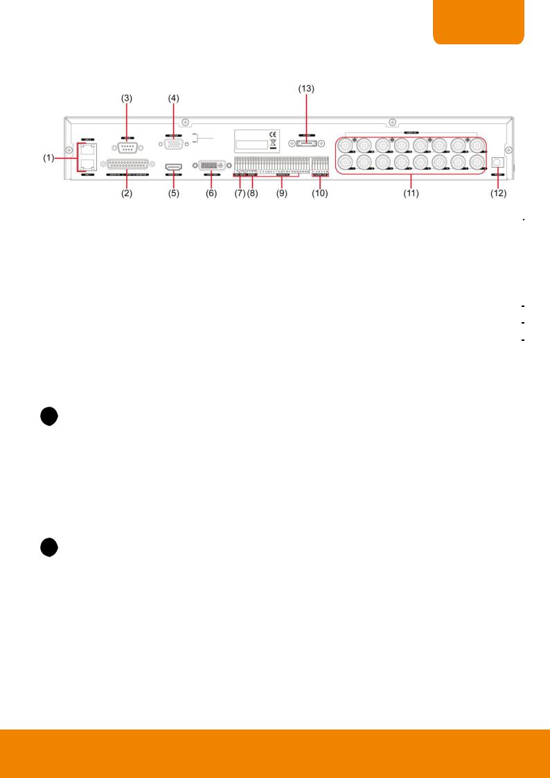
1.3.3 EH6216H+ (HDMI supported)
|
Name |
|
Function |
|
|
|
|
|
|
|
|||
(1) |
LAN 1/LAN 2 port |
|
For Gigabit Ethernet connection |
|||
|
|
|
|
|
||
(2) |
Audio IN/SPOT/TV |
|
- Audio input (red connector): 16 channels (sticker 1~16). To connect with camera’s |
|||
|
|
Monitor |
|
audio cable. |
||
|
|
|
|
|||
|
|
|
|
- Spot Monitor (sticker 2 on cable): 1 spot output. Outputs the analog video signals to |
||
|
|
|
|
Spot monitor when receive the alarm events. |
||
|
|
|
|
- TV output (sticker 1 on cable): 1 TV output. Output the video signal to a TV. |
|
|
(3) |
VGA Out |
|
Output the video signal to a CRT or LCD monitor |
|||
|
|
|
|
|
||
(4) |
RS232 port |
|
For POS device connection |
|||
|
|
|
|
|
||
(5) |
HDMI port |
|
Output the video signal to TV/HDMI monitor. |
|||
|
|
|
|
|
||
(6) |
Video Loop Out |
|
Output the analog video signal to a CCTV monitor. |
|||
|
|
|
|
|
||
(7) |
MIC/Audio |
|
MIC: To connect the microphone. |
|||
|
|
|
|
Audio: For audio output device connection, such as speaker. |
||
|
|
|
||||
|
i |
The audio input and output device has its own power supply is necessary. |
||||
|
|
|
|
|
||
|
|
|
|
|
||
(8) |
RS485 |
|
For analog PTZ camera connection (also see Chapter 1.4.3). |
|||
|
|
|
|
|
||
(9) |
Sensor In |
|
Support up to 16 sensor devices |
|||
|
|
|
|
|
||
(10) |
Relay Out |
|
Support 4 relay devices (Relay: 1A @ 125V AC/30V DC). |
|||
|
|
|
|
|
||
(11) |
CH1~ 16 |
|
Input the video camera signal and display it on channel 1~ 16. |
|||
|
|
|
|
|
||
(12) |
19V DC connector |
|
Connect the power adaptor into this port. |
|||
|
|
|
|
|
||
(13) |
eSATA port |
|
For connecting with HDD or RAID. |
|||
|
|
|
||||
|
i |
When connecting eSATA device, please make sure the DVR has installed hard disk to reduce abnormal |
||||
|
|
situation occurs. |
|
|
|
|
|
|
|
|
|
|
|
|
|
|
|
|
|
|
9
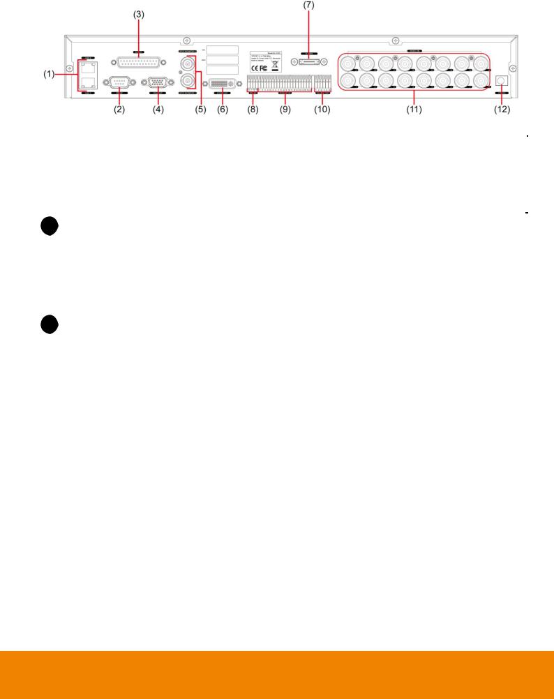
1.3.4 EH6216H+ (None HDMI)
|
Name |
|
Function |
|
|
|
|
|
|
|
|||
(14) |
LAN 1/LAN 2 port |
|
For Gigabit Ethernet connection |
|||
|
|
|
|
|
||
(15) |
RS232 port |
|
For POS device connection |
|||
|
|
|
|
|
|
|
(16) |
Audio port |
|
Input/output audio signal to audio input/output device. |
|||
|
- Audio input:16 channels |
|||||
|
|
|
|
|||
|
|
|
|
- Audio output: 1 channel |
||
|
|
|
|
- Microphone input: 1 channel |
||
|
i |
The audio input and output device has its own power supply is necessary. |
||||
|
|
|
|
|
||
|
|
|
|
|
||
(17) |
VGA Out |
|
Output the video signal to a CRT or LCD monitor |
|||
|
|
|
|
|
||
(18) |
SPOT Monitor 1/2 |
|
Output the analog video signal to SPOT monitor when receive the alarm events |
|||
|
|
|
|
|
||
(19) |
Video Loop Out |
|
Output the analog video signal to a CCTV monitor. |
|||
|
|
|
|
|
||
(20) |
eSATA port |
|
For connecting with HDD or RAID. |
|||
|
|
|
||||
|
i |
When connecting eSATA device, please make sure the DVR has installed hard disk to reduce abnormal |
||||
|
|
situation occurs. |
|
|
|
|
|
|
|
|
|
||
|
|
|
|
|
||
(21) |
RS485 |
|
For analog PTZ camera connection (also see Chapter 1.4.3). |
|||
|
|
|
|
|
||
(22) |
Sensor In |
|
Support up to 16 sensor devices |
|||
|
|
|
|
|
||
(23) |
Relay Out |
|
Support 4 relay devices (Relay: 1A @ 125V AC/30V DC). |
|||
|
|
|
|
|
||
(24) |
CH1~ 16 |
|
Input the video camera signal and display it on channel 1~ 16. |
|||
|
|
|
|
|
||
(25) |
19V DC connector |
|
Connect the power adaptor into this port. |
|||
|
|
|
|
|
|
|
10
CHAPTER 1
1.4Setting Up the DVR Unit
1.4.1 Installing the Hard Disks
i |
The external USB hard disk only supports on file backup. Please do not use the external USB hard disk for |
|
recording purpose. |
|
|
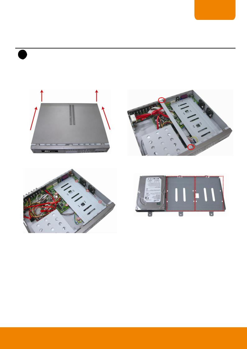
User can install up to 3 SATA hard disks inside the DVR unit if it is necessary.
Follow the illustrated instructions below to install the hard disk:
1.Loosen all screws (2 side and back) and push the cover backward and lift.
2.Loosen the screws of holder in order to take out the hard disk rack.
3. Loosen all the screws of hard disk plate.
4.The hard disk plate can be installed 3 hard disks. User can choose the position and place the hard disk on it.
11

5. Turn the plate and hard disk over carefully and screw the 6. Plug the SATA cable into SATA connector on the PC
hard disk on the plate. If hard disk cannot match to the screw hole, then, you may adjust the hard disk position to match the screw hole.
board.
[Note]
1.SATA 5 is for DVD player.
2.SATA 4 is for e-SATA interface
3.1st HDD is suggested to install on SATA 6.
4.The number of SATA connector is displayed nearby SATA connector.
7. Plug the power cable and SATA cable into hard disk. |
8. Plug the SATA cable into the left side hard disk. |
And then, screw the plate inside the DVR unit. |
|
User can leave un-plug the SATA cable of the left side HDD for screwing plate inside the DVR more easily later.
When user remove power cable from hard disk, please DO NOT pull the power cable straight way. Please pull out the power cable by moving power connector to left and right side and slowly pull out the power cable from hard disk.
12
CHAPTER 1
9. Screw the holder on the DVR unit. |
10. Push the cover forward and secure the cover. |
11. You may now connect all the cables and power on the DVR unit.
13
1.4.2 Connecting Devices
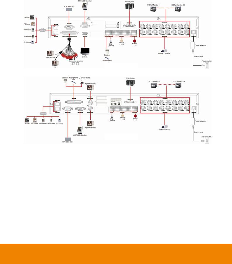
1.4.2.1EH6108H+
The back panel of the DVR unit, user can connect up to 8 cameras in both analog and IP camera. The DVR unit also can connect 16 sensor devices, 4 alarm devices, and output video to a TV or CRT/LCD monitor. Follow the illustration below to make the connection:
EH6108H+ with HDMI
EH6108H+ w/o HDMI
14
CHAPTER 1
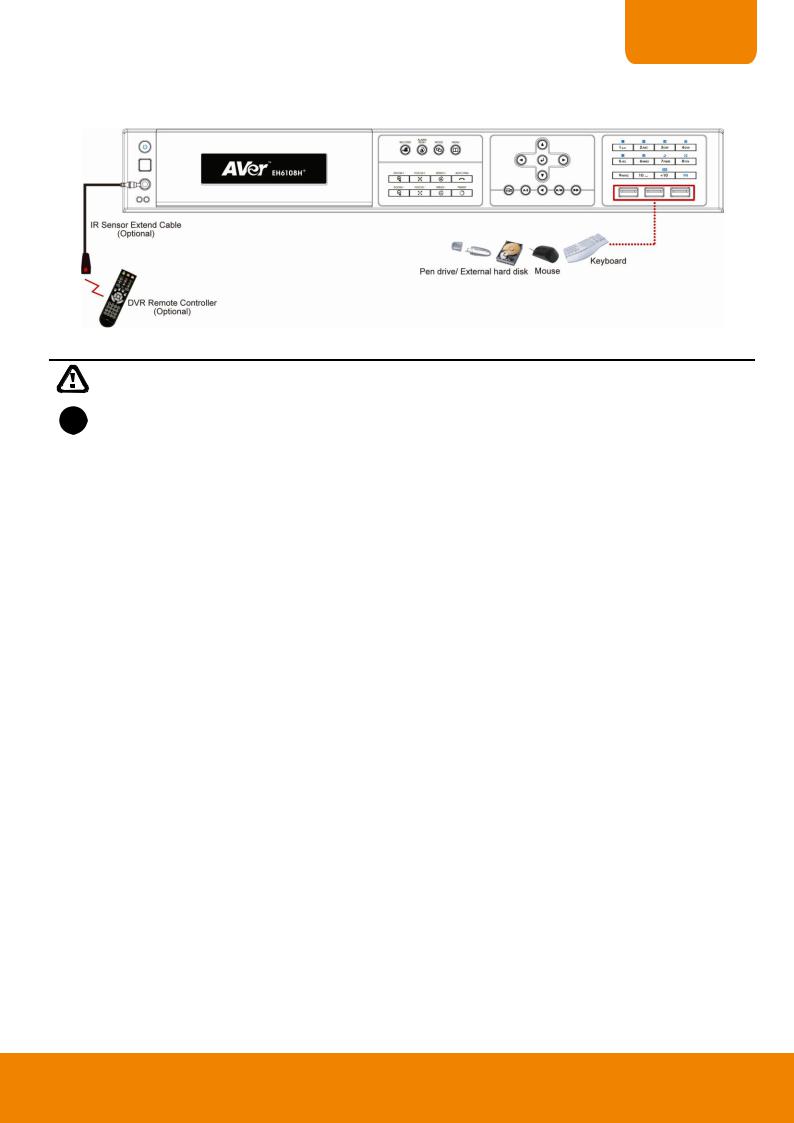
For backup recorded video, plugging the pen drive or external hard disk through USB port that are located at front panel of DVR unit, and then, use the bundled software enables user to transfer, playback and segment the video. Follow the illustration below to make the connection:
|
Pen drive and external hard disk must be FAT32 format. |
|
|
|
|
i |
– All connected devices have its own power supply is necessary. |
|
– DVR unit can connect 8 cameras in both of analog and IP cameras. |
||
|
||
|
|
15

1.4.2.2EH6216H+
The back panel of the DVR unit, user can connect up to 16 cameras in both analog and IP camera. The DVR unit also can connect 16 sensor devices, 4 alarm devices, and output video to a TV or CRT/LCD monitor. Follow the illustration below to make the connection:
EH6216H+ with HDMI
EH6216H+ w/o HDMI
16
CHAPTER 1
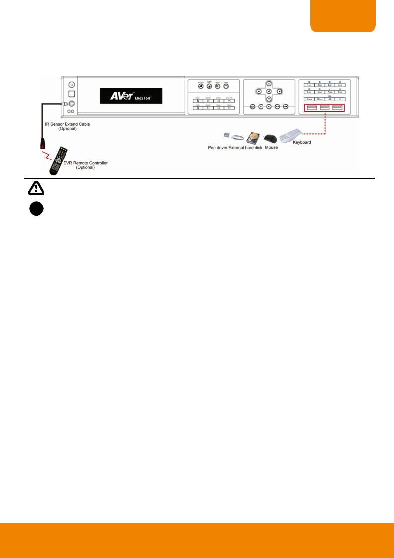
For backup recorded video, plugging the pen drive or external hard disk through USB port that are located at front panel of DVR unit, and then, use the bundled software enables user to transfer, playback and segment the video.
Follow the illustration below to make the connection:
|
Pen drive and external hard disk must be FAT32 format. |
|
|
|
|
i |
– All connected devices have its own power supply is necessary. |
|
– DVR unit can connect 16 cameras in both analog and IP cameras. |
||
|
||
|
|
17

1.4.3 Sensor, Relay and RS485 pinhole allocation
The Sensor and Alarm enable you to connect 16 sensor inputs, 4 relay outputs and PTZ cameras. Just connect the external sensor, relay, and PTZ camera pin directly to the pinhole. Check the table below and locate which pinhole is assigned to sensor input and relay output.
1.4.3.1Sensor Pin Definition
Sensor Pin # |
|
Definition |
Sensor Pin # |
Definition |
1 |
|
Sensor 1 signal |
9 |
Sensor 9 signal |
2 |
|
Sensor 2 signal |
10 |
Sensor 10 signal |
3 |
|
Sensor 3 signal |
11 |
Sensor 11 signal |
|
|
|
|
|
4 |
|
Sensor 4 signal |
12 |
Sensor 12 signal |
G |
|
Sensor ground |
G |
Sensor ground |
5 |
|
Sensor 5 signal |
13 |
Sensor 13 signal |
|
|
|
|
|
6 |
|
Sensor 6 signal |
14 |
Sensor 14 signal |
7 |
|
Sensor 7 signal |
15 |
Sensor 15 signal |
8 |
|
Sensor 8 signal |
16 |
Sensor 16 signal |
G |
|
Sensor ground |
G |
Sensor ground |
1.4.3.2 |
Relay Pin Definition |
|
|
|
|
|
|
|
|
Relay Pin # |
Definition |
|
|
1 |
Relay signal(N/O) |
|
|
2 |
Relay signal(N/O) |
|
|
G |
Relay ground |
|
|
3 |
Relay signal(N/O) |
|
|
4 |
Relay signal(N/O) |
|
|
G |
Relay ground |
18

CHAPTER 1
1.4.3.3RS485 Pin Definition
When connect PTZ camera through RS485 interface, please refer to the following pin definition to connect the DVR and PTZ.
|
|
Pin # |
DVR site |
PTZ site |
|
|
|
TX+ |
RS485 TX+ signal |
RS485 RX+ signal |
|
|
|
TX- |
RS485 TXsignal |
RS485 RXsignal |
|
|
|
RX+ |
RS485 RX+ signal |
RS485 TX+ signal |
|
|
|
RX- |
RS485 RXsignal |
RS485 TXsignal |
|
|
|
||||
i |
If user uses the 2 wires for the PTZ camera connection, please connect to the RS-485 TX+ and TX- |
||||
|
of the DVR site. |
|
|
|
|
|
|
|
|
|
|
19
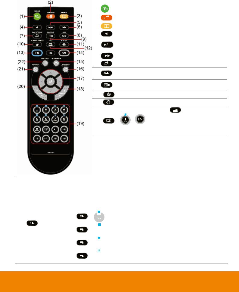
1.5Familiarizing the Remote Controller Buttons
Use the Remote controller to operate the DVR unit.
|
Name |
|
|
|
Function |
|
|
|
|
|
|
|
|||
(1) |
|
|
|
Switch to playback mode |
|
||
|
|
|
|
|
|
||
(2) |
|
|
|
Start recording video |
|
||
|
|
||||||
|
|
|
|
|
|
||
(3) |
|
|
|
To call out system setup menu |
|
||
|
|
|
|
|
|
||
(4) |
|
|
|
To rewind the recorded video |
|
||
|
|
|
|
|
|
|
|
(5) |
|
|
|
To start playback |
|
||
|
|
|
To pause playback |
|
|||
|
|
|
|
|
|
||
|
|
|
|
|
|
||
(6) |
|
|
|
To playback video at faster speed |
|
||
|
|
|
|
|
|
||
(7) |
|
|
|
To select the time and date of playback file |
|
||
(8)Set a playing recorded video from A point to B point segment and repeat playing on surveillance screen
(9)To backup recorded video file to USB storage device(pen drive or external hard disk) and DVD-ROM.
(10) |
To reset alarm status |
|
||
(11) |
Switch to Emap mode |
|
||
|
Switch to PTZ mode. Press |
+ channel number |
||
(12) |
( |
~ |
) can switch to PTZ control mode if the |
|
|
|
|
|
|
selected camera is a PTZ camera and the PTZ function is enabled.
|
Name |
|
Function |
|
|
|
|
||
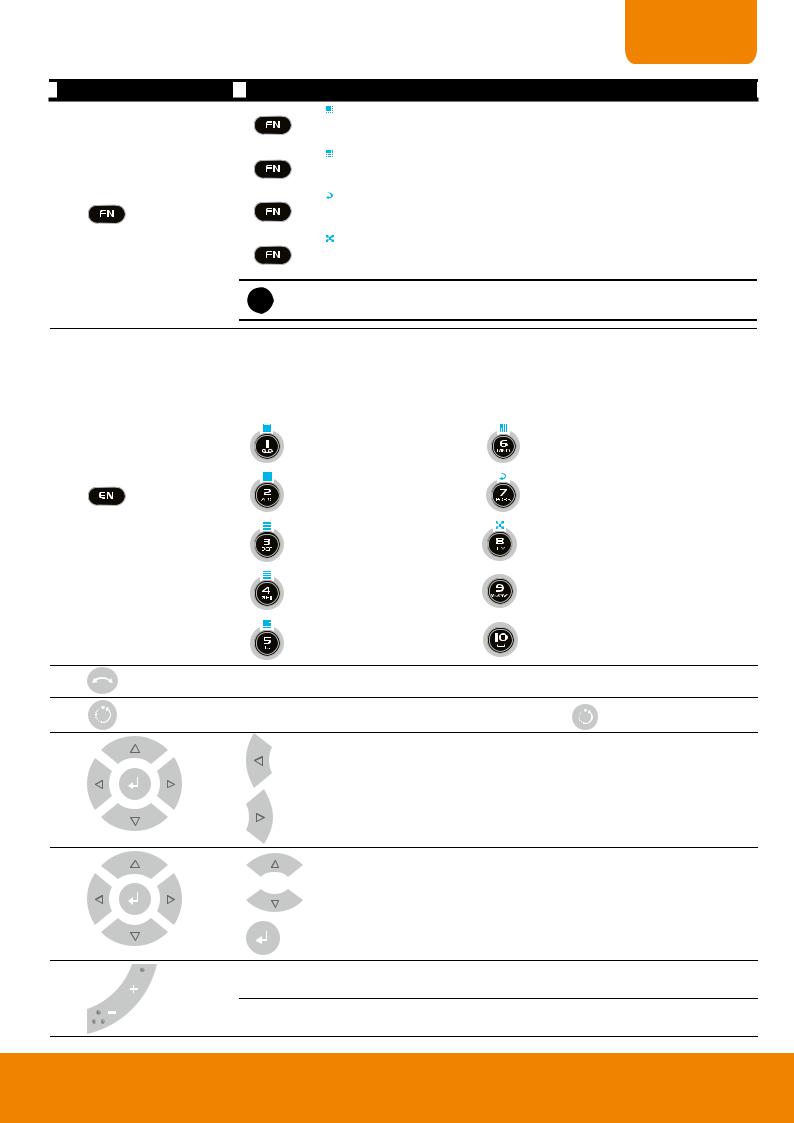
|
|
|
|
|
A functional key for multiple system control
-Press  to enable FN modes (The word “FN” will show up in the left bottom corner on screen).
-To exit FN modes, press  again (The “X” will show up in the left bottom
corner on screen).
+  : Switch to single screen display mode
(13)
+  : Switch to QUAD display mode
+  : Switch to 9 spilt screen display mode
+  : Switch to 16 spilt screen display mode
20
CHAPTER 1
 Name
Name
(13)
 Function
+  : Switch to one single and 7 + 1 spilt screen display mode
+  : Switch to one single and 12 + 1 spilt screen display mode
+  : Enable/disable auto scan
+  : Switch to full screen
i +
+  ~
~  doesn’t have any functions.
-Switch to character mode.
-Press  to enter EN mode (The word “EN” will show up in the left bottom corner on screen). User can press the character button and press rapidly to find
the character that wants to enter. Press  button again to exit EN mode
(The “X” will show up in the left bottom corner on screen).
|
: backward/delete button |
: mnoMNO |
|
(14) |
:abcABC |
: pqrsPQRS |
|
|
|
|
|
|
: defDEF |
: tuvTUV |
|
|
: ghiGHI |
: wxyzWXYZ |
|
|
: jklJKL |
: space button |
|
(15) |
To enable auto pan function |
|
|
(16) |
To move the PTZ camera to the preset position. Press |
+ number button. |
|
To move PTZ camera to left
(17)
To move PTZ camera to right
To move PTZ camera to up
(17) |
To move PTZ camera to down |
Confirm or make a selection

 Speed + : To speed up movement of PTZ camera lens (18)


Speed - :To speed down movement of PTZ camera lens
21
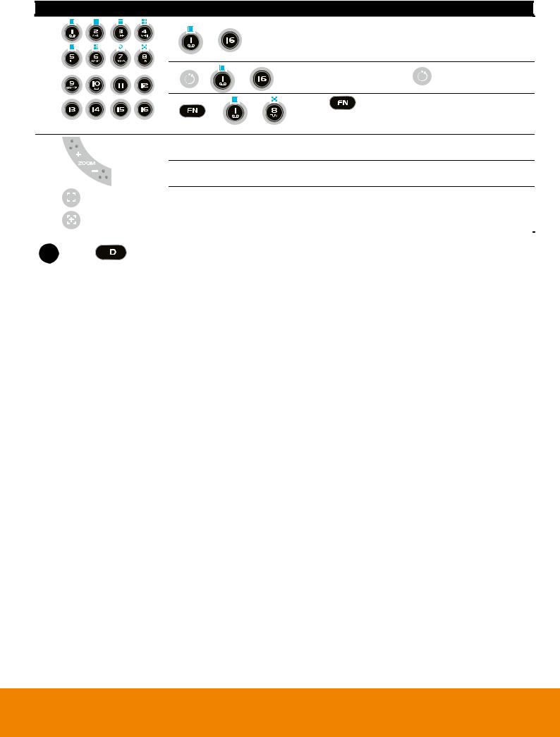
Name |
Function |
|
|
|
|
|
|
|
|
|
- As a number key for entering password in playback |
||
|
~ |
|
|
and preview mode |
|
|
|
|
|
- Channel camera selection number in playback and |
|||
|
|
|
|
|||
|
|
|
|
preview mode |
|
|
(19) |
|
|
|
As a preset position with |
at PTZ control mode |
|
|
+ |
~ |
|
|||
|
|
|
|
|
||
|
+ |
|
~ |
With |
button can switch to different screen |
|
|
|
display modes and enable auto scan and full screen. |
||||
|
|
|
|
|||
(see also Chapter 1.7 #(16))
Zoom + : To zoom in view of PTZ camera
(20)
Zoom - :To zoom out view of PTZ camera
(21) |
|
|
|
|
To focus out PTZ camera lens |
|
|
|
|||||
|
|
|||||
(22) |
|
|
|
|
|
|
|
|
|
|
To focus in PTZ camera lens |
||
|
|
|
|
|
|
|
|
|
|
|
|
||
i |
|
The |
|
button doesn’t support at this version. |
||
|
|
|||||
|
|
|
||||
|
|
|
|
|
|
|
22
 Loading...