


EVC950
Table of contents
 Loading...
EVC350/EVC950
EVC300/EVC900
User Manual

CONTENTS
INTRODUCTION ................................................................................................................... 1
Features ..............................................................................................................................................................1
Package Contents ..............................................................................................................................................2
INSTALLATION..................................................................................................................... 3
Getting Familiar with the EVC -Series................................................................................................................3
Main System ..................................................................................................................................................3
MIC .................................................................................................................................................................4
Camera...........................................................................................................................................................5
Remote Controller ..........................................................................................................................................6
Connections ........................................................................................................................................................8
Connecting Monitors (VGA Out/HDMI Out)...................................................................................................9
Connecting the Camera (Camera In) ............................................................................................................9
Connecting the MIC (MIC In) .......................................................................................................................10
Connecting the LAN (RJ-45)........................................................................................................................10
Connecting the Power (DC 12V) .................................................................................................................10
Connecting PC (VGA in/DVI In)...................................................................................................................11
Connecting the Audio (Audio In/Out)...........................................................................................................11
USB Storage (USB Ports)............................................................................................................................12
CAMERA AND MICROPHONE INTRODUCTION ................................................................... 13
Using the Camera .............................................................................................................................................13
Infrared Sensor (IR) ..........................................................................................................................................13
Positioning the MIC...........................................................................................................................................14
AVER EVC WIZARD SETUP ................................................................................................ 15
Start ..............................................................................................................................................................15
Language .....................................................................................................................................................16
Site Name ....................................................................................................................................................16
Network Setting............................................................................................................................................16
Public IP Configuration (Outside of Firewall): .............................................................................................17
Private IP Configuration (behind firewall port forwarding): .........................................................................18
SIP Setting ...................................................................................................................................................20
AVER EVC OPERATION ...................................................................................................... 23
Before You Begin..............................................................................................................................................23
Home Screen ....................................................................................................................................................23
Configuration Icons ......................................................................................................................................23
Camera and MIC Icons ................................................................................................................................24
WAN Address...............................................................................................................................................24
Real-Time Clock...........................................................................................................................................25
System Info ..................................................................................................................................................25
Dial ....................................................................................................................................................................26
Hang up the call ...........................................................................................................................................28

Video Layout ................................................................................................................................................28
Phonebook ........................................................................................................................................................29
Group ...........................................................................................................................................................29
New Site (Contact in Phonebook) ...............................................................................................................36
Contacts List ................................................................................................................................................40
Favorite ........................................................................................................................................................40
Online Phonebook .......................................................................................................................................41
Call History........................................................................................................................................................41
General Setting .................................................................................................................................................44
Call Settings .................................................................................................................................................44
System Settings ...........................................................................................................................................47
Administrator ................................................................................................................................................49
Monitor .........................................................................................................................................................53
Date and Time..............................................................................................................................................54
Reset System ...............................................................................................................................................57
License .........................................................................................................................................................58
Skype for Business License.........................................................................................................................59
Default Layout ..............................................................................................................................................60
Video/Audio.......................................................................................................................................................62
Camera.........................................................................................................................................................62
Microphone ..................................................................................................................................................65
Video/Audio Codecs ....................................................................................................................................68
Network .............................................................................................................................................................69
LAN Configuration........................................................................................................................................69
IPv6 ..............................................................................................................................................................71
Advance Network .........................................................................................................................................73
Firewall .........................................................................................................................................................74
SIP................................................................................................................................................................75
SIP Configuration .........................................................................................................................................79
Gatekeeper ..................................................................................................................................................84
Test Utilities..................................................................................................................................................87
Skype for Business ......................................................................................................................................88
iSCSI ............................................................................................................................................................89
WEB CONFIGURATIONS..................................................................................................... 90
Using the WebTool ...........................................................................................................................................90
Phonebook ........................................................................................................................................................93
Edit and Save ...............................................................................................................................................93
Download Phonebook Entries .....................................................................................................................94
Upload Phonebook Entries ..........................................................................................................................94
Download Call History Entries .....................................................................................................................94
LDAP Setting................................................................................................................................................95
Online Phonebook .......................................................................................................................................95
Upload Files Setting (Group Call Only) .......................................................................................................96

General Setting .................................................................................................................................................97
Enable Record .............................................................................................................................................97
Dual Stream Bandwidth Adjustment............................................................................................................97
Update System.............................................................................................................................................98
EZ Join .........................................................................................................................................................99
Customized Logo and Boot Animation ...........................................................................................................100
TROUBLESHOOTING ........................................................................................................ 101
Audio ...............................................................................................................................................................101
Video/Display ..................................................................................................................................................101
Network ...........................................................................................................................................................102
Others .............................................................................................................................................................104
SCENARIOS FOR LAN CONNECTION ............................................................................... 105
Public IP Configuration (Outside of Firewall) .................................................................................................105
Private IP Configuration (Behind Firewall with Port Forwarding) ..................................................................106
H.460 Gatekeeper with Firewall Traversal .....................................................................................................108
REMOTE CONTROL BATTERY SAFETY INFORMATION ................................................... 109
LIMITED WARRANTY........................................................................................................ 110
Limitations of Warranty ...................................................................................................................................110
Disclaimer of Warranty ...................................................................................................................................110
Limitation of Liability .......................................................................................................................................111
GOVERNING LAW AND YOUR RIGHTS ............................................................................. 111
FEDERAL COMMUNICATIONS COMMISSION STATEMENT (CLASS A) ............................. 111
Class A ITE .....................................................................................................................................................111
CE Class A (EMC) ..........................................................................................................................................111
COPYRIGHT ..................................................................................................................... 112
Trademarks .....................................................................................................................................................112
Disclaimer .......................................................................................................................................................112

1
Introduction
Thank you for choosing EVC300/EVC350/EVC900/EVC950 which offers professional
videoconferencing experience in new cost performance benchmark.
EVC300/EVC350/EVC900/EVC950 give you the latest technologies; slim form factor, flexible
integration options and backward compatibility to most videoconferencing install bases. It makes any
business meetings and special events much more reliable, effective, and secure.
Features
EVC300/350: 4-sites embedded MCU support H.323 and SIP protocol video conferencing system
EVC900/950:10-sites embedded MCU support H.323 and SIP protocol video conferencing
system
Support full content sharing experience (send and receive) at 30fps, send content from VGA or
HDMI
Dual monitor support via HDMI1 and HDMI2/VGA
Support CIF (352x240) up to Full HD (1920x1080 30fps) video call
EVC300/EVC900 with PTZ camera is 16x Optics PTZ camera with 2Mp low lux sensor
EVC350/EVC950 with PTZ camera II is 18x Total zoom PTZ camera with 2Mp low lux sensor
Include one microphone array, much better audio pick up than competitor offering
10/100 and Gigabit Ethernet; video bandwidth from 64Kbps to 4Mbps
Support IPv4/IPv6 and Wake-on-LAN (WOL)
User-friendly on screen operation, support up to 22languages
Support Phonebook download, upload and edit
Call history lookups of received, placed and missed calls, allow directly saving it to favorite
contact list
Support H.460 Gatekeeper for NAT and firewall traversal
G.722.1C* wideband support
Infrared (IR) remote control has power button; system supports remote API for AV integration
Secure communication using AES 128bit encryption
*:G.722.1/G.722.1C, licensed from Polycom
®

2
Package Contents
The following items are included in the package. Please check if each item is available before using.
1
2
/
3
4
5
6
7
8
9
10
11
12
13
14
15
16
Internet
Camera
Mic
PC / LaptopPC / Laptop
Audio InSpeakerDisplay 1Display 2 (HDMI)Display 2 (VGA)
1. Main System
2. Camera
3. Microphone
4. Remote Control
5. Power Adapter
6. Power Cord
7. VGA Cable
8. Mini Din 8 pin MIC Cable (5m)
9. HDMI Cable * 2
10. Camera Cable (3m)
11. RJ-45 Cable (3m)
12. DVI to HDMI Connecter
13. Warranty Card
14. Quick Installation Guide
15. AAA Batteries
16. Back Panel Label
The power cord will vary depending on the standard power outlet of the country where it is sold.
The camera will vary depending on choosing EVC model of EVC300/EVC350/EVC900/EVC950.
3
Installation
Getting Familiar with the EVC -Series
EVC includes Main System, MIC, Camera and Remote Controller.
Main System
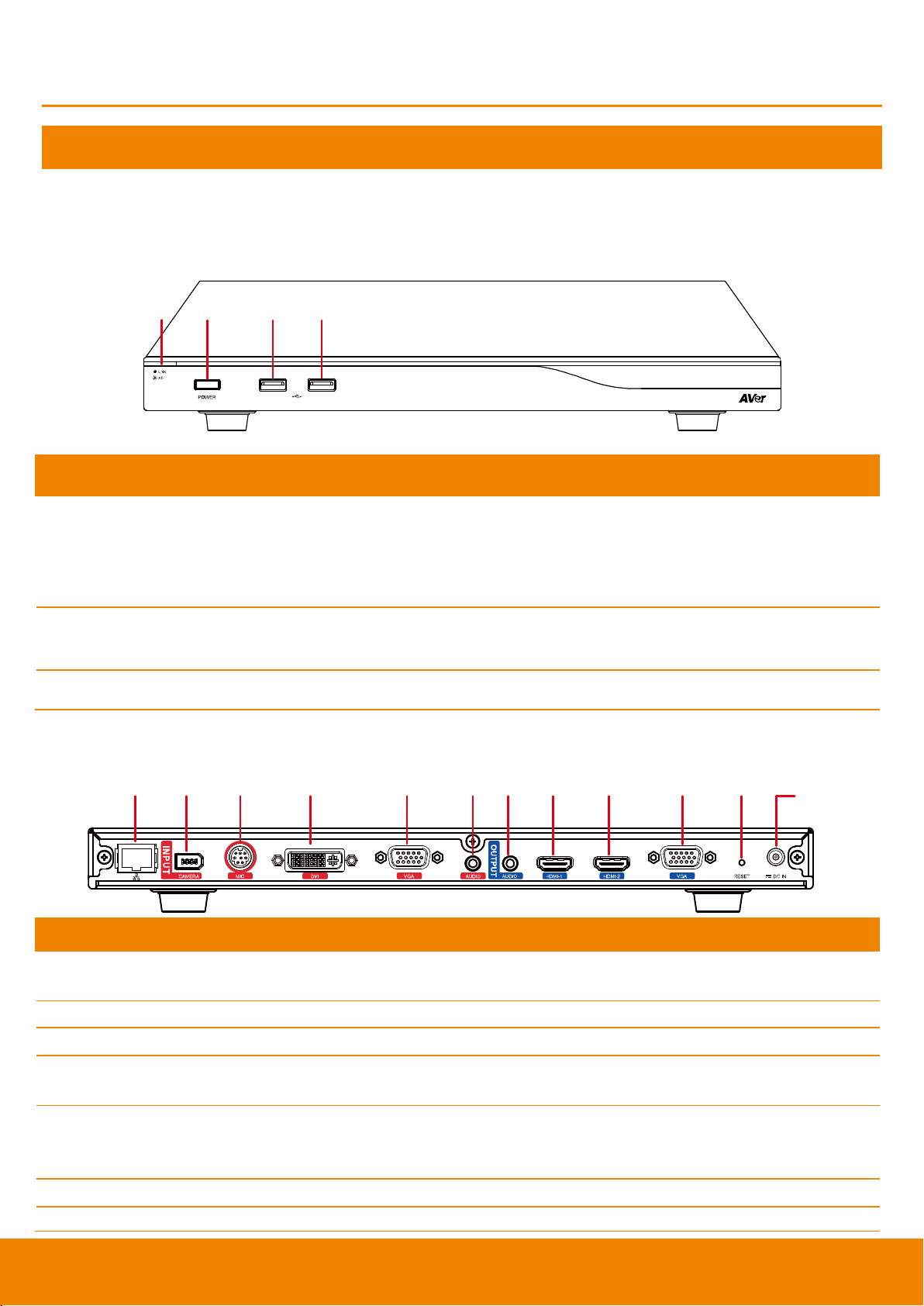
Front Panel:
(2)(1) (3) (4)
Name
Function
(1) LED Indicator
Show you the status of your LAN connection.
1. Solid Green: LAN connection is successfully
2. Flash Green: Data transmission is processing through the LAN
connection.
(2) POWER Button
Press this button to turn on/off main system. Red: power off; Blue: power
on
(3) & (4) USB Port
Use to connect the USB storage for system log saving and FW upgrade.
Back Panel:
(1) (2) (3) (4) (5) (6)(7) (8) (9) (10) (11)
(12)
Name
Function
(1) LAN Port
Use the RJ-45 Ethernet cable to connect an IP-based network to the LAN
port.
(2) CAMERA IN Port
Connect the camera to the main system via a camera cable.
(3) MIC IN Port
Receive audio signal from MIC device via a mini din 8 pin MIC cable.
(4) DVI IN Port
Using the DVI to HDMI connector to transfer the DVI to HDMI interface and
through the HDMI cable connects to the PC or NB.
(5) VGA IN Port
Connect the VGA cable to the VGA input port located on the back panel, and
connect the other end of VGA cable to a VGA input source (ex. Document
camera, Laptop or Desktop) to input video signal.
(6) AUDIO IN Port
Receive audio signal from an external audio source through the audio cable.
(7) AUDIO OUT Port
Use to connect the main system to external speakers or amplifiers for audio

4
Name
Function
signal output.
(8) HDMI-1 Port
Connect an HDMI cable from the HDMI monitor to HDMI-1 output port
located on the back panel. The HDMI interface allows you to transmit both
audio and video signals over a single cable (HDMI cable). In dual screen
configuration, the output screen connected to this port will be set up to
primary screen automatically.
(9) HDMI-2 Port
Connect the HDMI cable to the HDMI-2 output port located on the back
panel, and connect the other end of HDMI cable to a display device to output
both video and audio signal. In dual screen configuration, the output screen
connected to this port will be set up to secondary screen automatically.
(10) VGA OUT Port
Connect the VGA cable to the VGA output port located on the back panel,
and connect the other end of VGA cable to a display device to output video
signal. In dual screen configuration, the output screen connected to this port
will be set up to secondary screen automatically.
(11) RESET Button
Press it to reboot the main system unit.
(12) POWER Port
Connect the power supply cord and adapter to the power port located on the
back panel. And connect the other end of the power cord to a suitable power
outlet.
MIC
Name
Function
(1) Mute
Mute/Unmute the Mic. Blue: Unmute; Red: Mute
(2) MIC OUT Port
Outputs audio signal from the MIC to main system.
(3) MIC IN Port
Receive audio signal from the second MIC and pass it through the MIC
OUT to the main system.

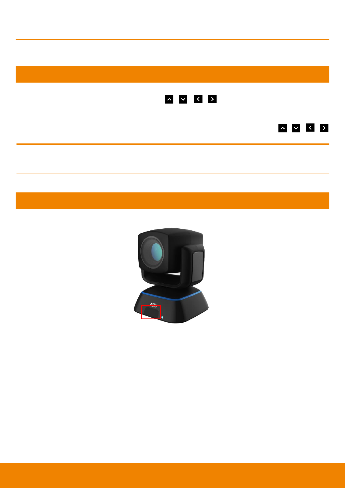
5
Camera
Name
Function
(1) IR Sensor
Receive IR signal from the remote control for system operation. Amber
light blinks when it detects key pressing event from remote.
(2) CAMERA OUT Port
Connect the camera cable to the CAMERA OUT port located on the back
of camera and CAMERA IN port located on the back panel of main
system for a video transmission.

6
Remote Controller
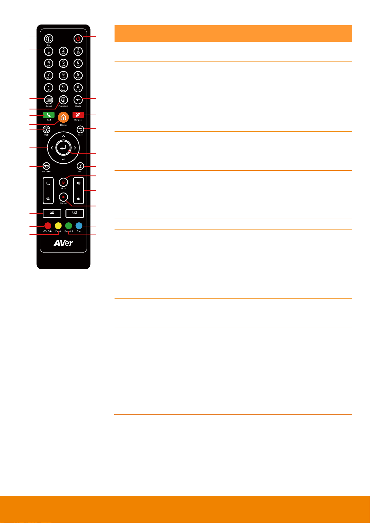
The remote controller requires two “AAA” batteries (included). Make sure the batteries are installed
properly before using the remote controller. Aim the remote controller at the infrared sensor of your
AVer EVC camera to remote control the unit.
Zoom
Layout
Vol
Presentat ion
(1)
(3)
(4)
(7)
(5)
(10)
(12)
(14)
(16)
(20)
(22)
(23)
(2)
(6)
(9)
(8)
(11)
(15)
(18)
(17)
(21)
(25)
(24)
(13)
(19)
Name
Function
(1) Info
Press this button to display the call statistics
information.
(2) Power
Press this button to power on/off the main
system.
(3) Numeric Pad
a. Use to enter alphanumeric. Press
button and hold can switch between
numeric mode and alphanumeric mode.
b. Press number button 0~ 9 to switch the
number frame in main(enlarge) view while
conferencing call ( When Voice Activated
Layout Switch is disabled).
(4) Keypad
In enter mode, press this button to display the
on-screen keyboard.
(5) Phonebook
Search contacts to make a call.
Add, edit, delete or create group contact
entries.
(6) Delete
Press this button to back delete one character
at a time.
(7) Call
Start a call.
(8) Home
Bring up the main screen.
(9) Hang up
End the call.
(10) Help
In Home menu and video screen mode, press
it to display on-screen help information.
(11) Back
Return to previous OSD menu.
(12) Navigation
Buttons
( , , , )
c. Use these buttons to navigate through
the selections in OSD menus or
on-screen keyboard.
d. Pan and tilt the camera to adjust the
viewing.
e. Pan, tilt the zoomed in camera image or
captured image.
(13) Enter
a. Make a selection in OSD menus.
b. Accept incoming calls.
c. Display the site name and icon during
the meeting.
d. Auto Focus function(PTZ camera only)
(14) Far/Near
Select to control either near site or far site
camera. The cam ctrl icon will appear on the
screen to indicate which site’s camera you
are controlling. The cam ctrl icon will
disappear after press the Far/Near key 5 sec.
7
Zoom
Layout
Vol
Presentat ion
(1)
(3)
(4)
(7)
(5)
(10)
(12)
(14)
(16)
(20)
(22)
(23)
(2)
(6)
(9)
(8)
(11)
(15)
(18)
(17)
(21)
(25)
(24)
(13)
(19)
Name
Function
(15) Input
Switch screen display between camera
screen and input source screen.
(16) Zoom +/-
Increase/decrease the camera zoom or the
captured image magnifications.
(17) Vol +/-
Increase/decrease the speaker volume.
(18) Mute
Mute/Unmute the MIC. The mute icon will
appear when the MIC is muted. The mute
icon will become translucent after enabling 5
sec.
(19) Record
Start/Stop video recording. The video
recording can only be saved to a USB flash
drive. You do not need to be on a video
conference to record.
(20) Presentation
Share the content that comes from either the
VGA input source or the DVI input source.
The present icon will appear on the screen
when the presentation function is enabled.
The icon will disappear after 5 sec.
(21) Layout
Change the screen layout.
(22) AVer Point
While using EZDraw, press AVer point button
can share EZDraw screen view on EVC
presentation view.
(23) Preset
Press and hold for 3 sec. to set the position of
the camera to a preset from 0~99.
Press to move the camera to a selected
preset point number.
(24) Snapshot
Capture the image from the camera(OSD
menu is not included) and save to external
USB pen drive.
(25) Dual
Switch to dual screen mode. This splits
the video conferencing screen and
present screen onto two separate
monitors (two monitors must be
connected to use the feature, one
through HDMI and one through
VGA/HDMI-2).
Press and hold can switch to OSD menu
between primary and secondary screen.
8
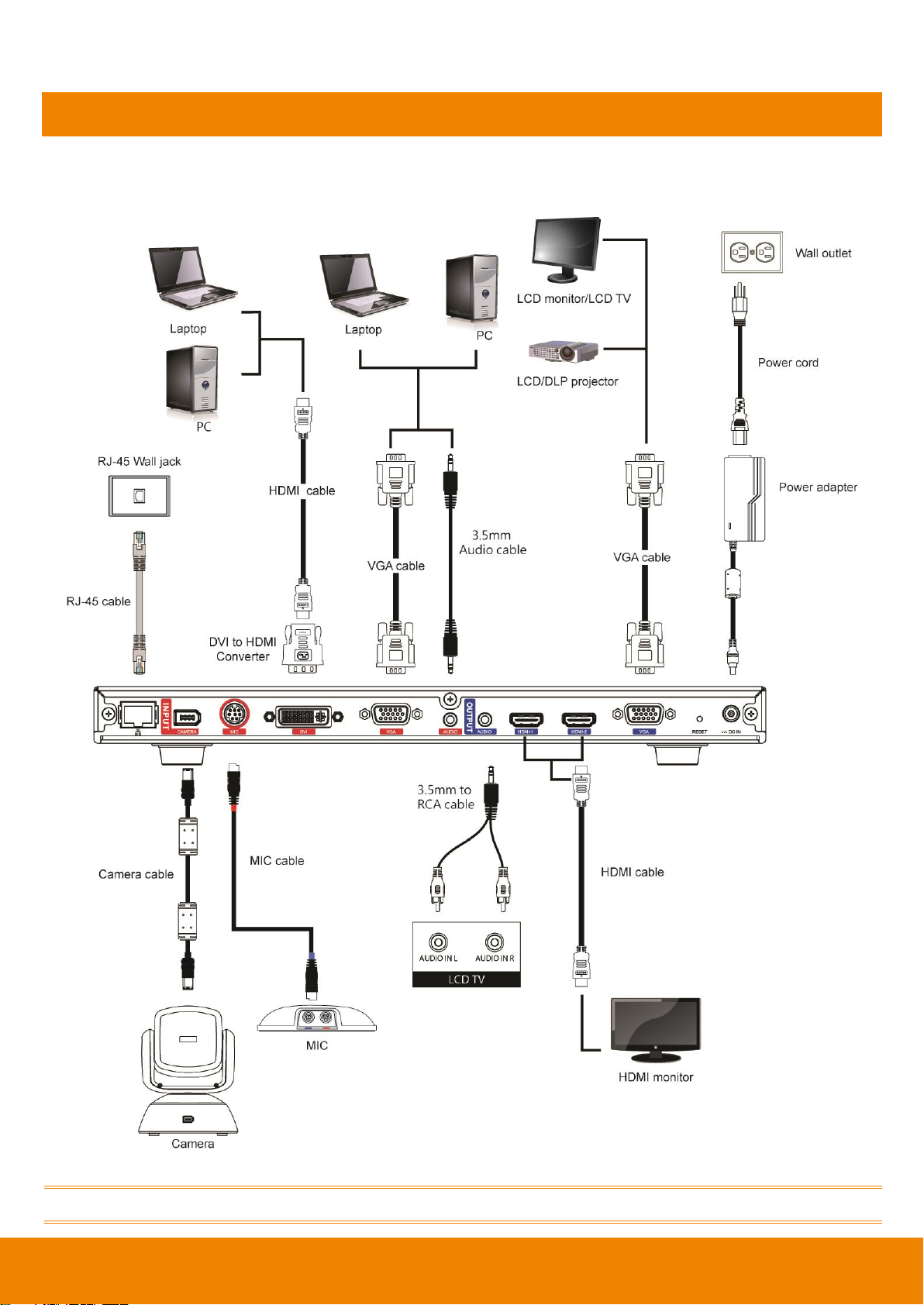
Connections
Before making the connections, make sure all devices are powered off. Refer to the illustrated
connections below and also to the user manual of the device you are connecting to the EVC300 /
EVC350 / EVC900 / EVC950 system.
Make sure all connections have been connected successfully before powering on the system.
9
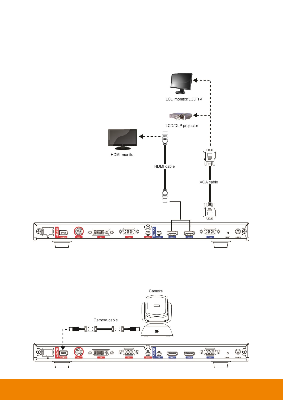
Connecting Monitors (VGA Out/HDMI Out)
Locate the VGA/HDMI input port of the graphics display device and connect it to VGA OUT/HDMI
OUT port of the AVer EVC with the supplied VGA/HDMI cable. You can connect the VGA OUT and
HDMI-1 OUT ports or HDMI-1 OUT and HDMI-2 ports at the same time upon a dual screen
configuration. The HDMI-2 output and VGA output port displays screen scene and resolution are
same.
Connecting the Camera (Camera In)
Locate the port on the back of the camera and connect it to the CAMERA IN port of the EVC with the
supplied camera cable.
10
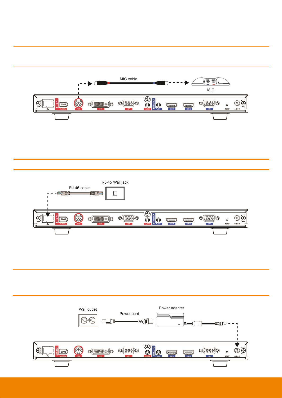
Connecting the MIC (MIC In)
Use the supplied MIC cable and connect the red tag connector to the MIC IN port of the EVC. Then
connect the other end of the MIC cable with the blue tag to MIC OUT port.
Press the button on the top of AVer EVC-MIC to mute/un-mute the MIC.
Please connect the cable to the port follow by the color on the cable and port, ex. red to red.
Connecting the LAN (RJ-45)
Connect the LAN port of AVer EVC to a RJ-45 wall jack or Ethernet hub with the supplied RJ-45
cable.
It is requires an IP-based network before beginning LAN connection.
Connecting the Power (DC 12V)
Connect the power adapter to a standard 100V~240V AC power outlet with the supplied power
adapter and power cord.
(1) To prevent shock, make sure all the connections on the main system are connected
successfully before connecting the power cable and turning on the power.
(2) Make sure to use the supplied available power adapter.
11
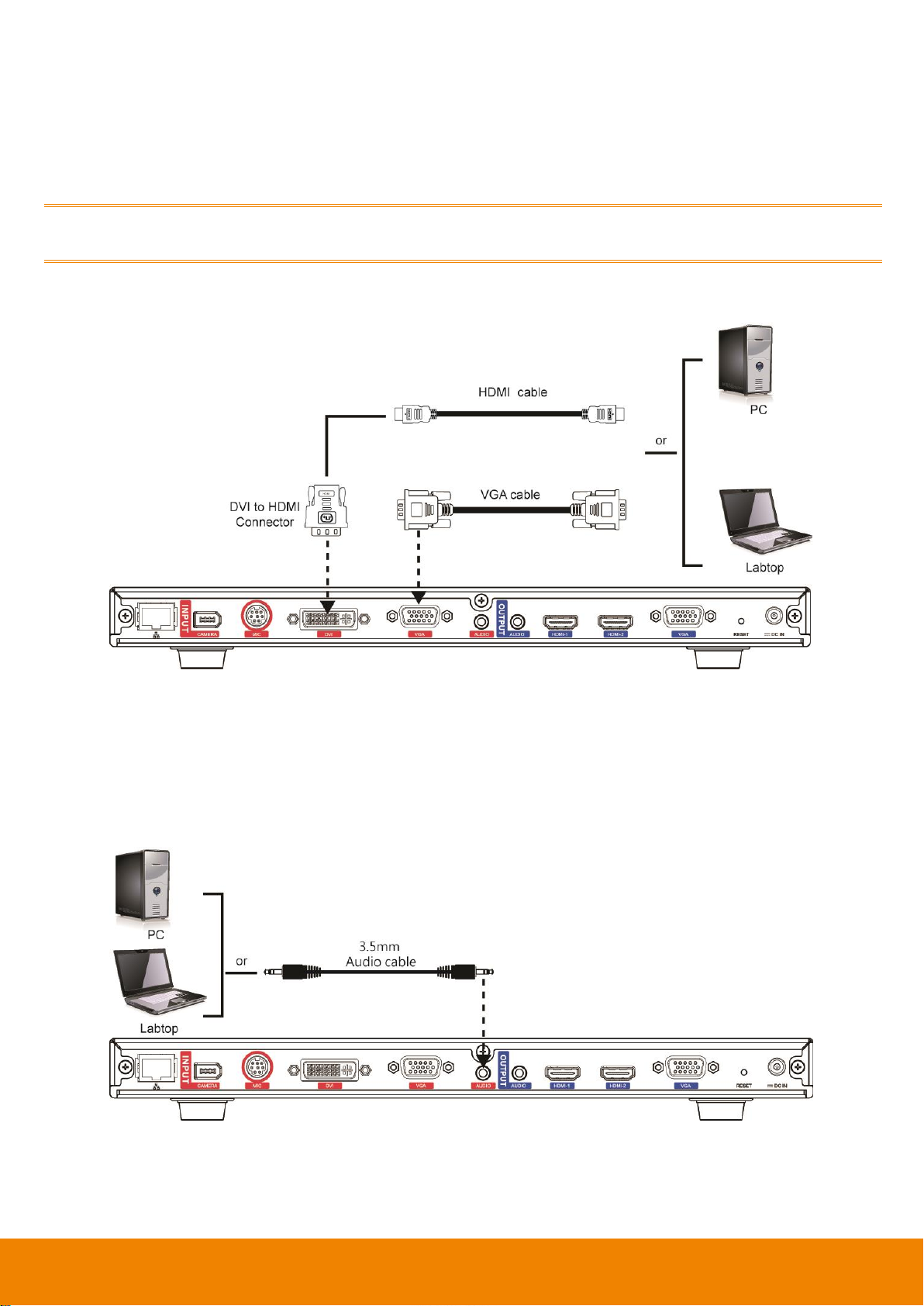
Connecting PC (VGA in/DVI In)
Locate the VGA output port of the Laptop or Desktop and connect it to VGA IN port of EVC with the
supplied VGA cable for an image display.
Use the supplied DVI to HDMI connector and connect to the HDMI port of Laptop or Desktop with
HDMI cable.
To share the video signal from the computer, press PRESENTATION and select “VGA” or ”DVI”
source.
Connecting the Audio (Audio In/Out)
AUDIO IN:
Locate the AUDIO output port of the Laptop or Desktop and connect it to AUDIO IN port of AVer EVC
with the supplied 3.5mm Audio cable.
12
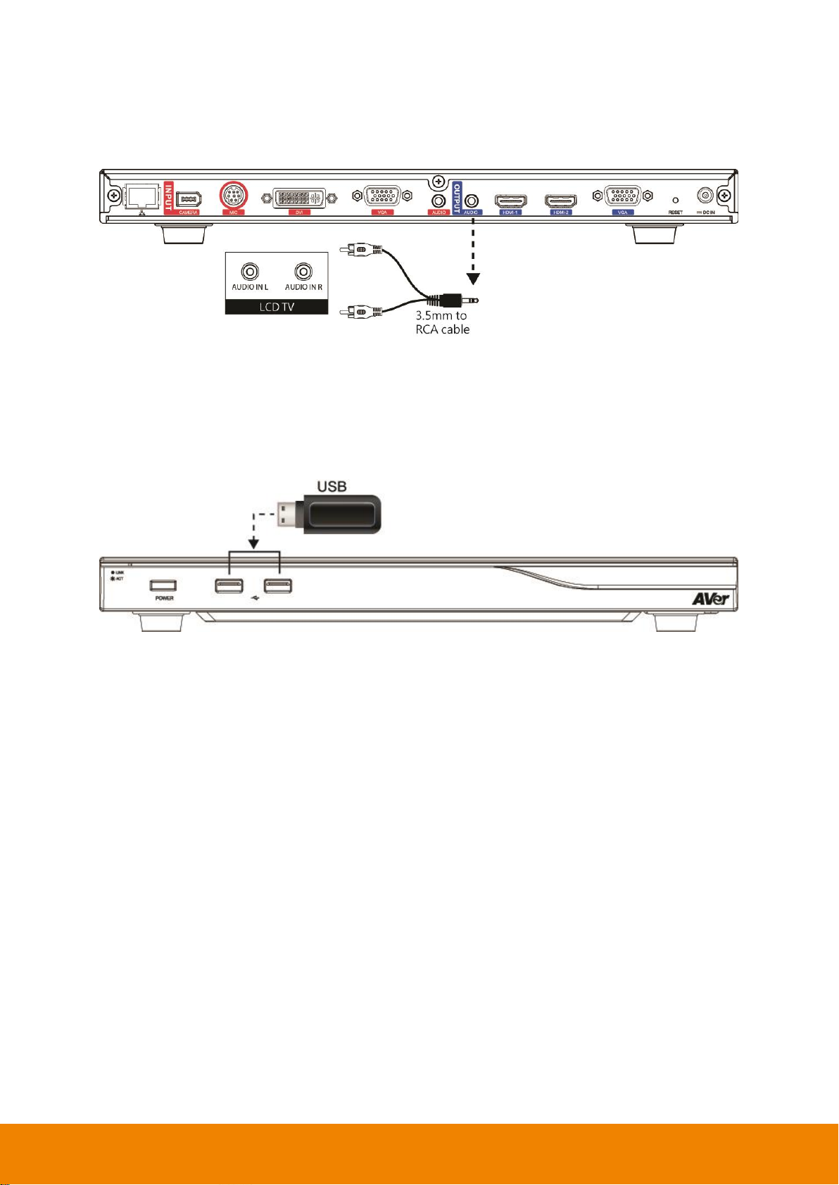
AUDIO OUT:
Locate the AUDIO in port of the LCD TV speaker or normal speaker and connect them to AUDIO OUT
port of EVC with a RCA cable.
USB Storage (USB Ports)
EVC main system supports two USB2.0 interface for saving data.
[Note] The USB ports only support USB pen drive for F/W upgrading and saving log file; they DO
NOT supply 5V power for any external devices.
13
Camera and Microphone Introduction
This chapter explains the best way to position EVC300 / EVC350 / EVC900 / EVC950 in a conference
room.
Using the Camera
EVC300 / EVC900 includes a detached camera that can pan (+-100 deg. range), tilt (+-25 deg.
range) and zoom (16x Optics) by using the , , , and zoom +/- buttons on remote
controller.
EVC350 / EVC950 includes a detached camera that can pan (+-130 deg. range), tilt (+90/-25 deg.
range) and zoom (18x total zoom with 12x Optical, 1.5x Digital zoom) by using the , , ,
and zoom +/- buttons on remote controller.
Avoid physically turn camera while system is powered on to prevent permanent damaging the
motors and gears and void the warranty. Always use the remote control to pan and tilt the camera
head.
Infrared Sensor (IR)
Aim the remote controller at the camera infrared sensor to operate the unit.
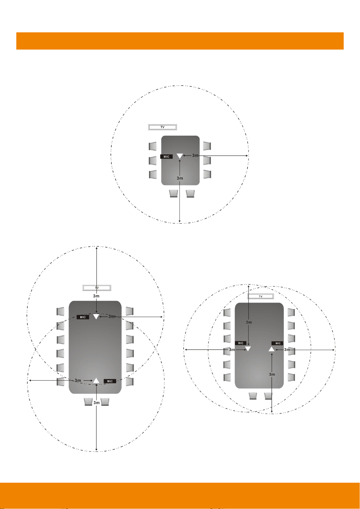
14
Positioning the MIC
The best distance for EVC-MIC to receive audio signal is within 3m. The EVC-MIC can connect up to
4 in one chain.
Single Microphone
Two Microphones
15
AVer EVC Wizard Setup
For the first time using AVer EVC system, the Installation Wizard will guide the user to setup EVC
system step by step. After completing the wizard setup, user may start to use the EVC system.
In Installation Wizard, user can use the following buttons on remote controller to move between the
selections and make/confirm selection.
: To expand the drop-down list, make/confirm the selection.
/ : Move the cursor up or down.
: Move the cursor to right or on Next button.
: Move the cursor to left or on Back button.
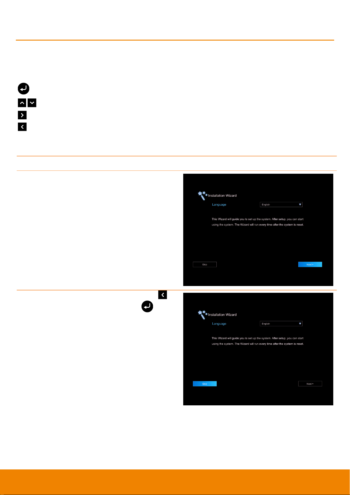
Start
Please follow the below description to complete the wizard setup.
Connect your EVC system well and turn on the
power. After your EVC system starting, user will
see the Installation Wizard screen shown up.
If you want to pass the Wizard setup, press
button move to Skip button and press to go
to Home page.
16
Language
Select the language of the EVC system.
Press to expand the drop-down list. Then,
use or button to move the selection and
press to make the selection. After selecting,
press to move to Next option and press
to go next step.
Site Name
Assign a name for EVC system. Use the numeric pad on remote controller to enter the site
name.
After entering the site name, press to move to
Next button and press to go next step.
To go back to last step, press to move to Back
option and press to confirm.
[Note]
(1) Repeat press the number button to select the
character that user wants to enter.
(2) The site name is character only
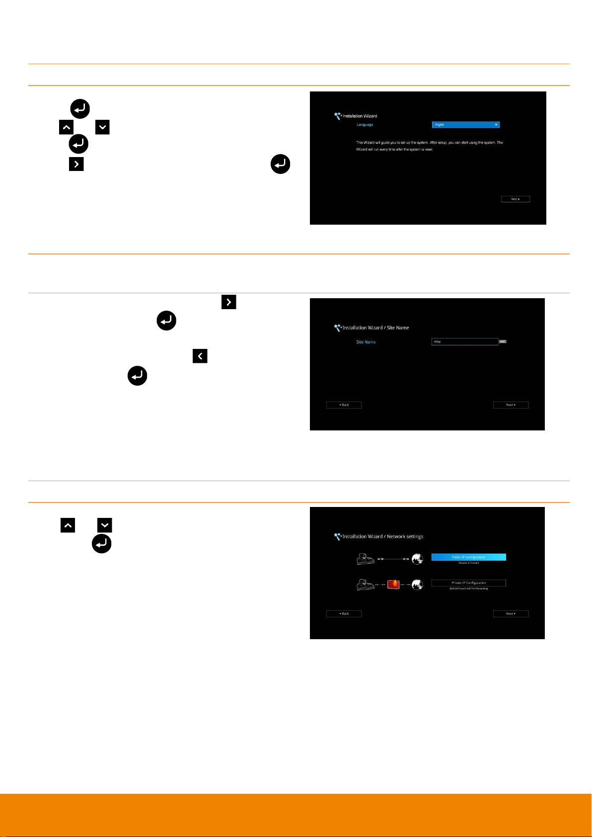
Network Setting
Select the network environment that user has used.
Use or button to move to the selection
and press to confirm the selection.
[Note] User can refer to chapter of Scenarios For
LAN Connection for the description of network
environment.
After selecting the network setting option, user
need to configure the network parameters. Follow
the below description to setup the network
settings.
17
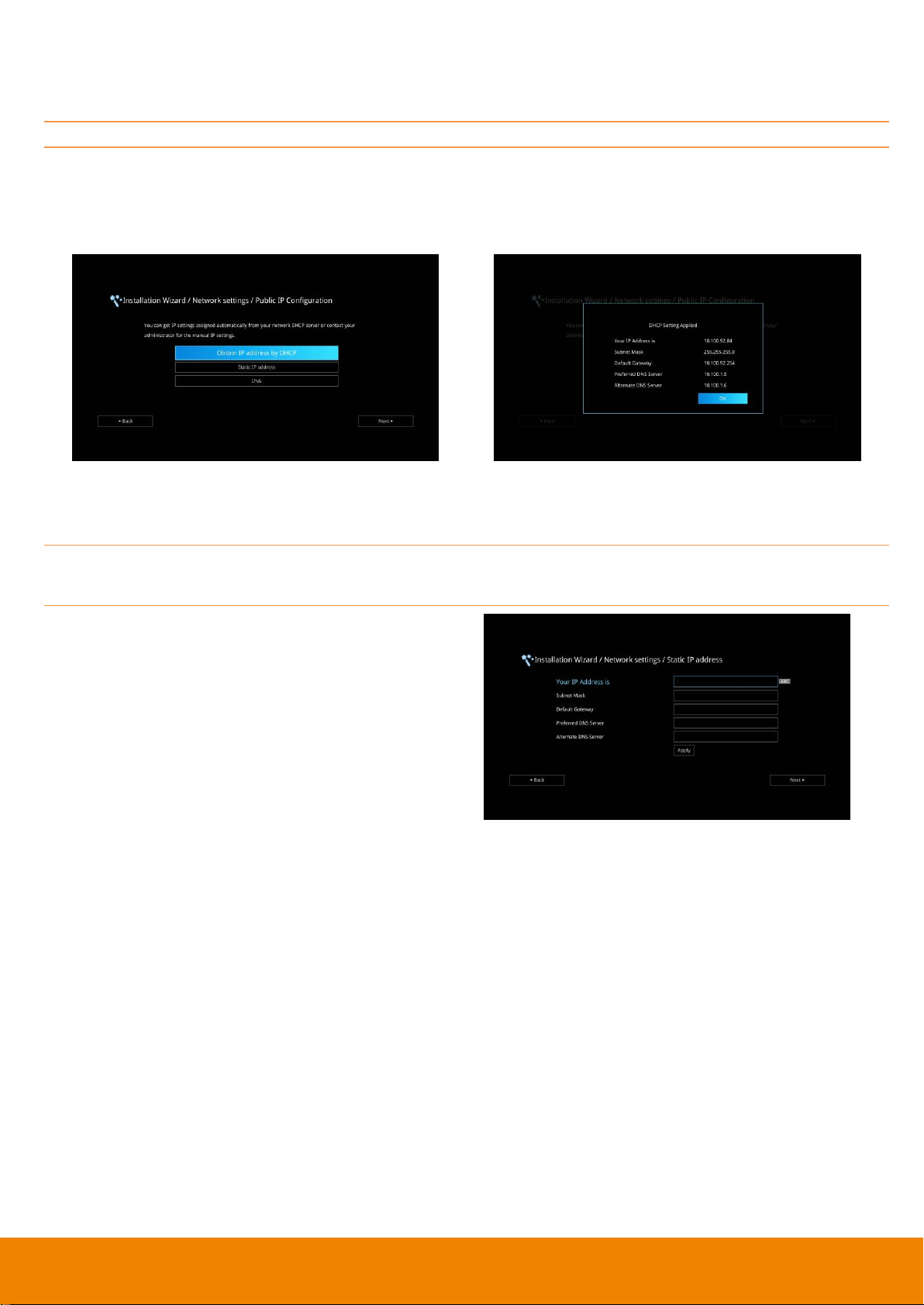
Public IP Configuration (Outside of Firewall):
Your EVC system is connecting directly to the internet. Select the IP mode.
Obtain IP address by DHCP: Configure the system to automatically obtain an IP address from the
DHCP server. The EVC system will automatically get an IP address which assigned by your DHCP
server on LAN. The IP address and related information will display. Click OK to accept the setting.
Static IP: Configure the system to use the assigned IP address. Select this when the public IP
address is available.
Enter the following information and click Apply to save the settings. To go to next step, click Next
and click Back to go back to Network Setting page.
1. Your IP Address is: Enter your IP address
manually.
2. Subnet Mask: Enter the subnet mask address
when the system does not automatically obtain
the subnet mask
3. Default Gateway: A gateway is a network
point that acts as an entrance to another
network. Enter the gateway address when the
system does not automatically obtain the
gateway.
4. Preferred DNS Server: Domain Name
System (DNS) servers convert human friendly
names (for example: www.example.com) to IP
addresses (218.77.272.166) that let machines
be found on the network. The preferred DNS
server is the one your computer asks first. The
alternate is a backup. Enter the Preferred and
Alternated DNS Server address.
5. Alternate DNS Server: Enter another Domain
Name server for second choice.
18
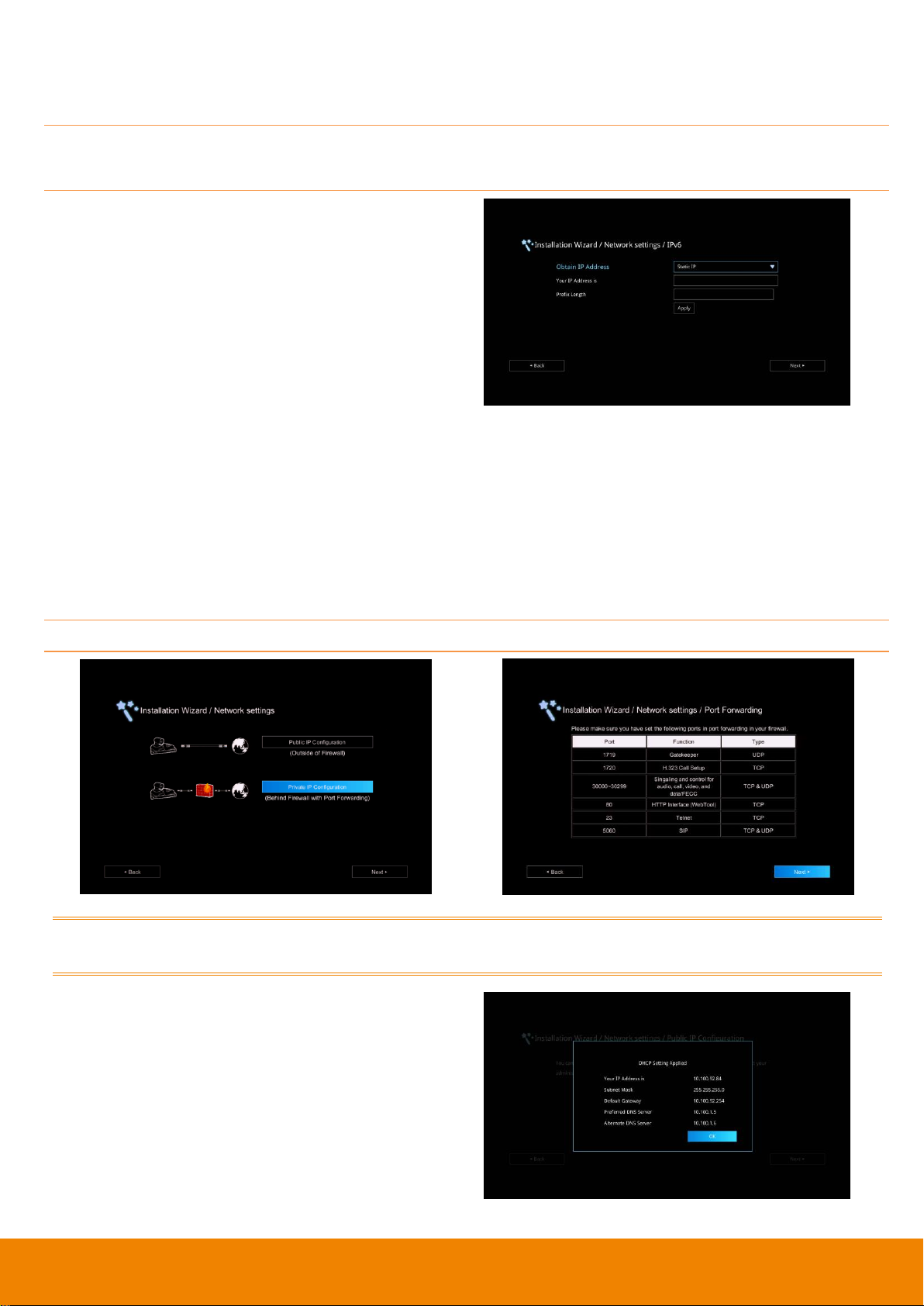
IPv6: IPv6 is an evolutionary upgrade to the Internet Protocol. IPv6 will coexist with the older IPv4 for
some time. IPv6 addresses are 128-bit IP address written in hexadecimal and separated by colons.
Select and enter the following information and click Apply to save the settings. To go to next step,
click Next option and click Back to go back to Network Setting step.
1. Obtain Address is
(1) Static IP: Configure the system to use
the assigned IP address. Select this
when the public IP address is available.
(2) Auto: Obtain the dynamic IP address
automatically. User needs to enter the IP
address and prefix length in following.
2. Your IP Address is: Enter your IP address
manually.
3. Prefix Length: Prefix Length allows you to
place as many IPv6 devices as the underlying
network medium allows.
Private IP Configuration (behind firewall port forwarding):
Your EVC system is connecting to the internet through a firewall.
Please make sure you have set the following ports in port forwarding in your firewall. Then, click
Next to select the IP mode of your network
Obtain IP address by DHCP: Configure the
system to automatically obtain an IP address from
the DHCP server. The EVC system will
automatically get a IP address which assigned by
your DHCP server on LAN. The IP address and
related information will display. Click OK to accept
the setting.
19
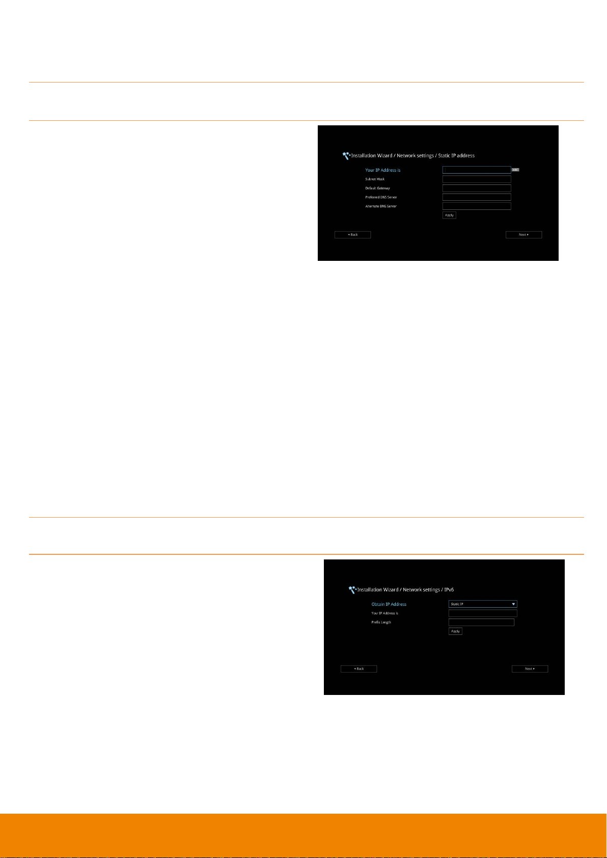
Static IP: Configure the system to use the assigned IP address. Select this when the public IP
address is available.
Enter the following information and click Apply to save the settings. To go to next step, click Next
and click Back to go back to Network Setting page.
1. Your IP Address is: Enter your IP address
manually.
2. Subnet Mask: Enter the subnet mask address
when the system does not automatically obtain
the subnet mask
3. Default Gateway: A gateway is a network
point that acts as an entrance to another
network. Enter the gateway address when the
system does not automatically obtain the
gateway.
4. Preferred DNS Server: Domain Name
System (DNS) servers convert human friendly
names (for example: www.example.com) to IP
addresses (218.77.272.166) that let machines
be found on the network. The preferred DNS
server is the one your computer asks first. The
alternate is a backup. Enter the Preferred and
Alternated DNS Server address.
5. Alternate DNS Server: Enter another Domain
Name server for second choice.
IPv6: IPv6 is an evolutionary upgrade to the Internet Protocol. IPv6 will coexist with the older IPv4 for
some time. IPv6 addresses are 128-bit IP address written in hexadecimal and separated by colons.
Select and enter the following information and click Apply to save the settings. To go to next step,
click Next option and click Back to go back to Network Setting step.
1. Obtain Address is
(1) Static IP: Configure the system to use
the assigned IP address. Select this
when the public IP address is available.
(2) Auto: Obtain the dynamic IP address
automatically. User needs to enter the IP
address and prefix length in following.
2. Your IP Address is: Enter your IP address
manually.
3. Prefix Length: Prefix Length allows you to
place as many IPv6 devices as the underlying
network medium allows.
20
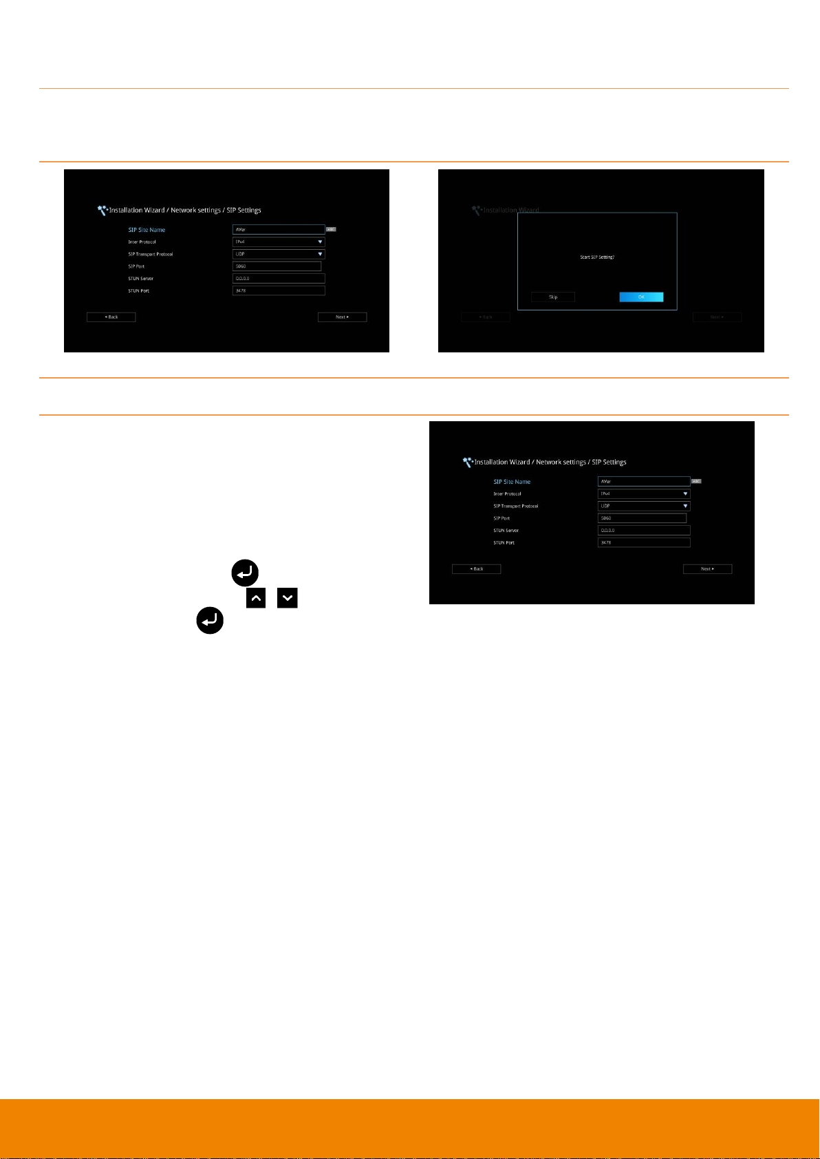
SIP Setting
Session Initiation Protocol (SIP) allows you around the world to communicate using your supported
devices over the Internet. After setting network, user can choose to setup SIP or Skip SIP setting.
To setup SIP, enter or select the following information
1. SIP Site Name: Enter the SIP site name for
others to identify. The SIP site name may be
the same or different then the domain for Web
activity. Use numeric pad to enter the SIP site
name in column.
2. Internet Protocol: Select to use IPv4 or IPv6
as IP protocol. Press to expand
drop-down list and use , to move the
selection. Press to confirm the selection.
3. SIP Transport Protocol: Select the SIP
Transport Protocol type from the drop-down list
for using. There are two types of Internet
Protocol (IP) traffic. They are Transmission
Control Protocol (TCP) and User Datagram
Protocol (UDP). To ensure proper connection,
verify if both calling parties are using the same
transport protocol. By default, it is set to UDP.
(1) TCP: TCP is connection oriented. Once a
connection is established, data can be sent
bidirectional.
(2) UDP: UDP is a simpler, connectionless
Internet protocol. Multiple messages are
sent as packets in chunks using UDP.
4. SIP Port: Change this value only if you use
specific settings in your network system. By
default, the SIP port is set to 5060.
5. STUN Server: STUN (Session Traversal
Utilities for NAT) is a standardized set of
methods and a network protocol to allow an
end host to discover its public IP address if it
is located behind NAT.
6. STUN Port: Enter the port number of STUN
server.
21
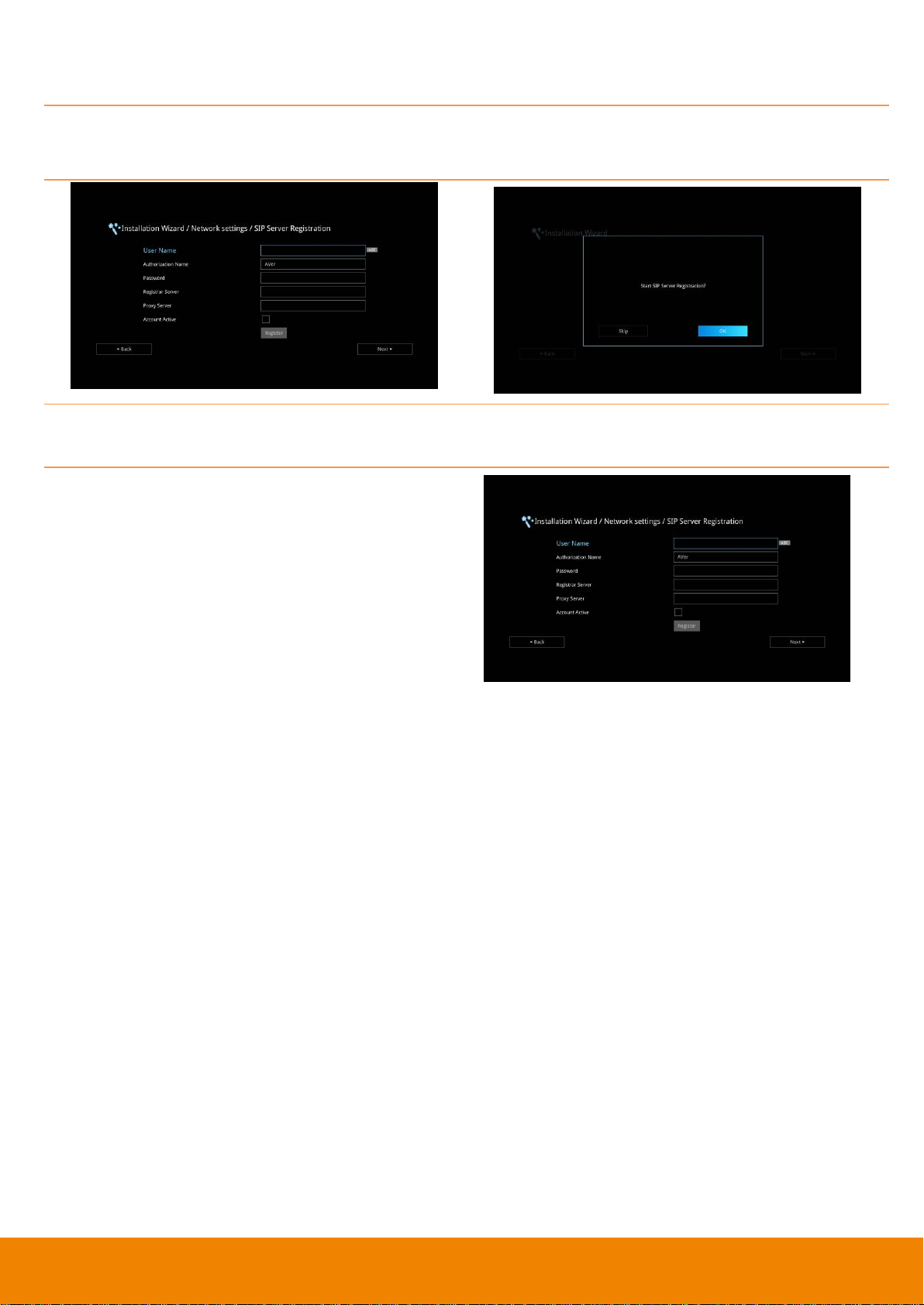
SIP Server Registration
A typical SIP session involves a client requesting a session with a SIP server. After the request is
received, the SIP server returns a response to the user indicating the availability of the session.
After setting SIP, user can choose to setup SIP Server Registration or Skip.
To setup SIP Server Registration, enter the following information and click Register to save the
settings. After completing, click Next to go next step.
1. Terminal Name: Enter the terminal server
name.
2. Terminal Password: Enter the password of
terminal server.
3. Registrar Server: Registrar Server accepts
registrations from users and places these
registrations, (which is essentially location
information), in a database known as a
location service. Enter the Registrar Server
name that you want to use.
4. Proxy Server: Proxy Server is computing
device (typically a server) that interfaces
between data processing devices and others
within a communications network. These
devices may be located on the same local area
network or an external network. Enter the used
Proxy Server name.
22
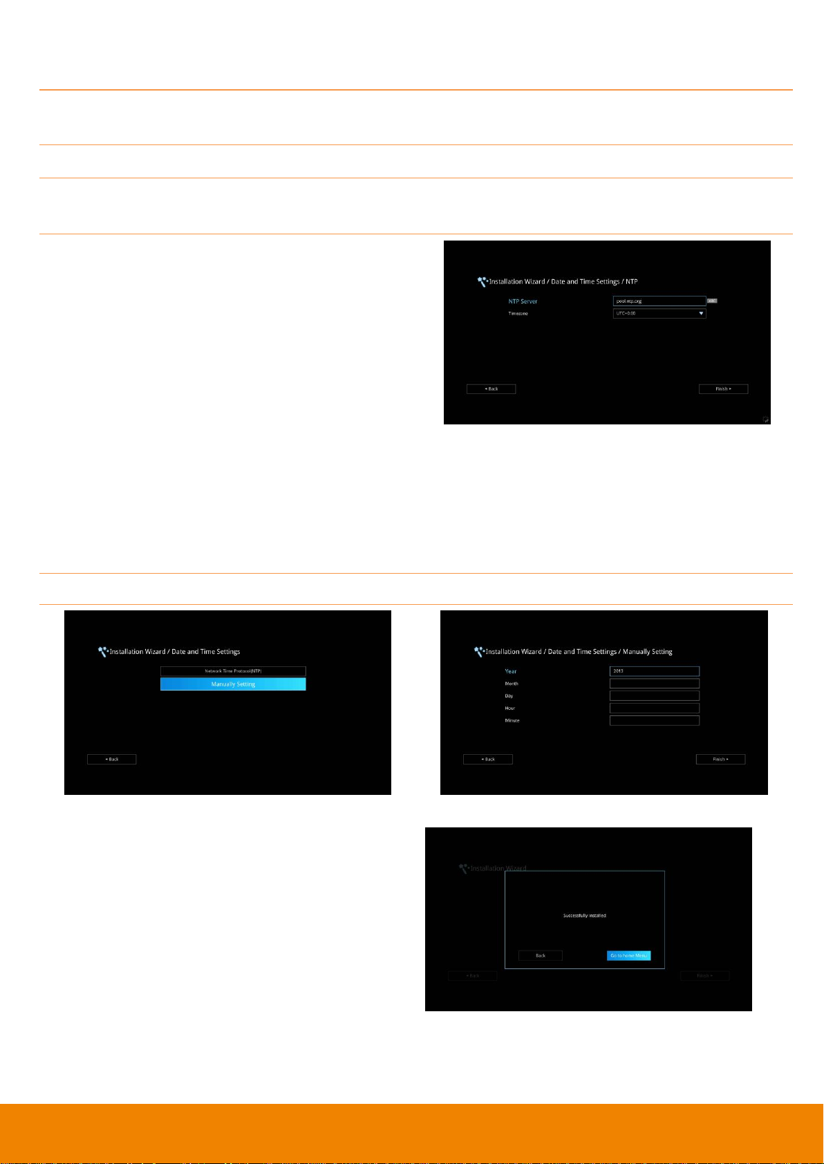
Date and Time Setting
Setup the EVC system date and time. User can choose to use NTP server to adjust the date/time or
manually enter the current date/time.
Network Time Protocol (NTP)
Network Time Protocol (NTP) is a protocol that is used to synchronize system clock times in a
network of device.
1. NTP Server: The Network Time Protocol (NTP)
allows administrators to synchronize all
network computers to a main server. This
keeps all network machine clocks on the same
time. Enter the NTP Server name that you
want to follow.
2. Time Zone: Timezone allows you to adjust the
time when you are in a different country or
area so that you can keep the same time with
your original area. Most of the time zones on
land are offset from Coordinated Universal
Time (UTC) by a whole number of hours
(UTC-12 to UTC+14)
Manually Setting
Enter the present year, month, date, hour, minute, and second by yourself
After completing date/time setup, click Finish to
complete the Installation Wizard setup. Before
that, user can back to previous page or go to
home menu. How to dial a call; refer to chapter of
Making a Call.
23
AVer EVC OPERATION
Connecting the camera, microphone, main system, display and power, press the power button to turn
on EVC. Power button starts blinking blue light, AVer logo shows up followed by an animation and
music. In 30 seconds camera image and home screen appear on screen. Aim the remote controller to
camera and start configuring AVer EVC.
Before You Begin
Basic Operation
Navigation buttons: Use the , , and buttons to move the selection on the remote
controller.
Enter button: Use the to confirm the selection on the remote controller.
Apply: Make the changed value to take effect. (For EVC Application)
Save: Accept the created value and save it to the system.
Cancel: Cancel the changed value and exit the present screen.
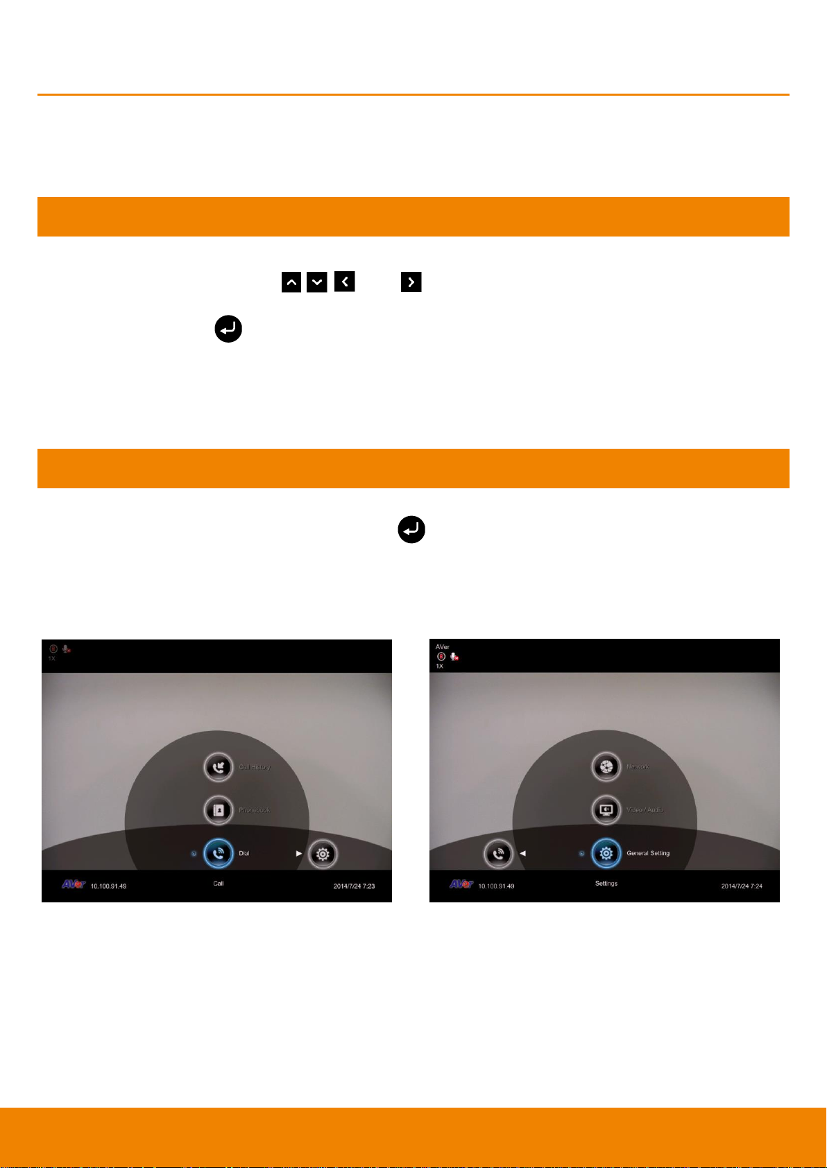
Home Screen
There are 2 selections divided on the Home screen: Call and Setting. Simply use the navigation
buttons to move between selections and press to confirm the selection. You can easily place a
call and select the site contact either in Dial, Phonebook or Call History. You can easily setup up the
system in General Setting, Video/Audio, and Network. The administrator can set a security
password to prevent changes made to the system setting and WebTool access.
Configuration Icons
Call include Dial, Phonebook and Call History
Setting include General Setting, Video/Audio and
Network.
Menu function is divided into 2 parts – Call and Setting.
Call function is included Dial, Phonebook and Call History.
Setting function is included General Setting, Video/Audio, and Network.

24
Camera and MIC Icons
On the upper left-hand corner of your home
screen, you may see camera and MIC
indications.
When camera is removed, “Camera
Disconnected” warning message is displayed
and screen is blue.
When is displayed on that screen, it
means far site remote can be operated by
remote controller.
is displayed indicating microphone is mute.
Try pressing the mute button on microphone or
remote controller to unmute it (LED indicator on
microphone turns blue).
WAN Address
On the lower left corner of your home screen,
you can find current WAN IP address.
25
Real-Time Clock
On the lower right corner of your home screen,
you can find the current Date and Time once
system sets up properly.
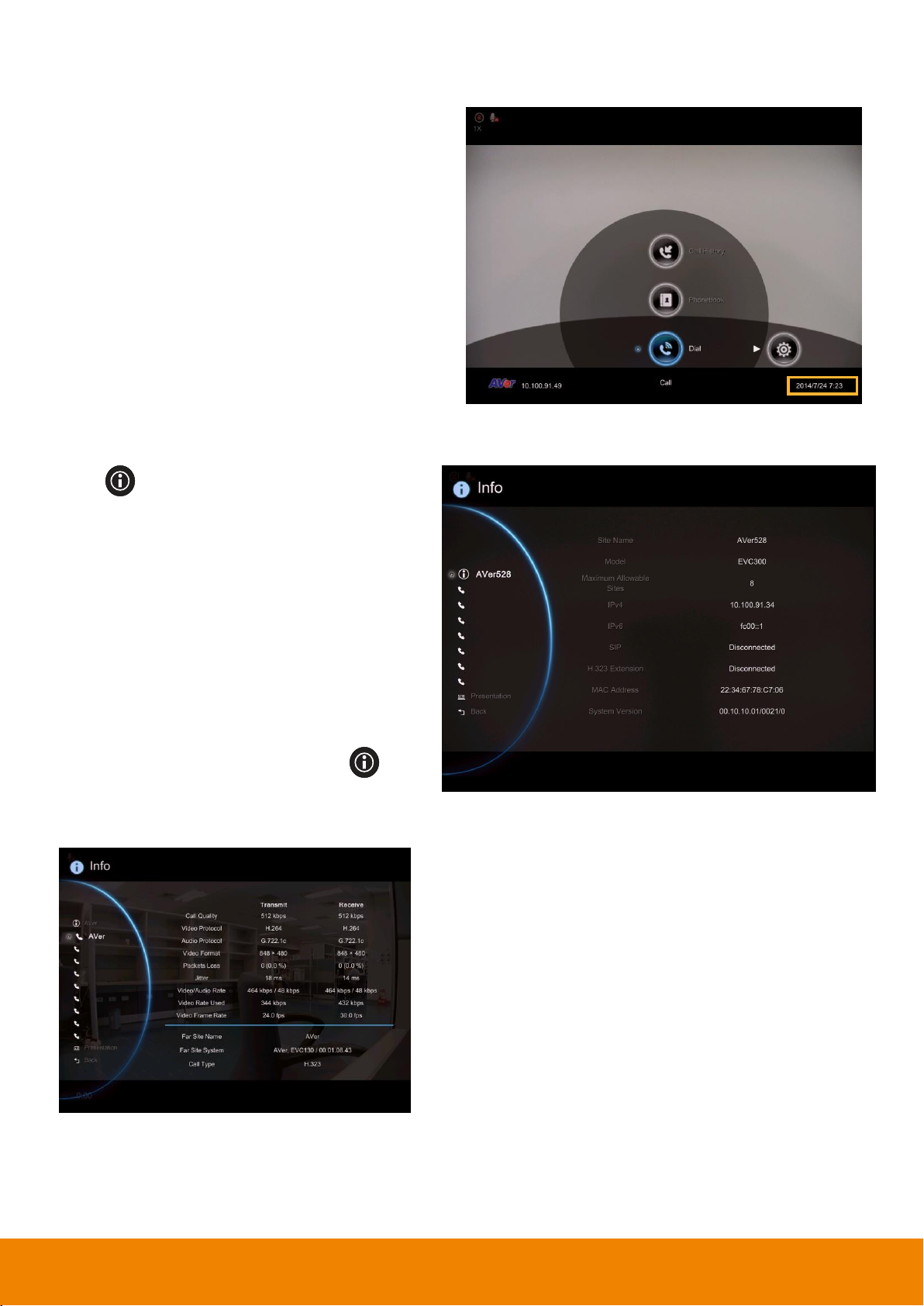
System Info
Press (Info) button to switch to system
information page.
The System Info shows you the relative
information about your EVC main system
including Site Name, Model name, Maximum
Allowable Sites, IP Address, MAC Address
and System Version.
Also, you can view call status while call is
connected.
1. Make a call.
2. When call is connected, press (Info)
button.
3. Select the call and you should see the
current call status.

26
Dial
Dial selection allows you to enter dial screen and
make a call.. Press button on the remote
controller has the same effect.
Call to
Use the number keys on the remote controller to
enter the IP address or number or SIP URI
(sip:username.password@host) you want to call.
AVer remote controller supports alpha-numeric
operation, press numeric key multiple times to
select the alphabet or symbol.
[Note] Press button and hold can switch
between numeric mode(123) and alphanumeric
mode(ABC/123).
Call Type
AVer EVC supports H.32, SIP, SIP Only Voice
calls. H.323 is commonly used to communication
to other videoconferencing room systems. SIP is
commonly used to communicate with other VoIP
devices. SIP Only Voice is used when other
conference site could not recognize EVC video
code, only transfer voice. Use the button to
select which type of call type you want to make
then press to confirm.
[Note] H.322 and SIP call type can be existed in
a same conference call meeting.
Loading...