


 Loading...
CAM520 Pro
User Manual

Federal Communications Commission Statement
NOTE: This equipment has been tested and found to comply with the limits for a Class A digital device, pursuant to part 15 of the FCC Rules. These limits are designed to pro-vide reasonable protection against harmful interference when the equipment is
operate din a commercial environment. This equipment generates, uses, and can radiate radiofrequency energy and, if not installed and used in accordance with the instruction manual, may cause harmful interference to radio communications. Operation of this equipment in a residential area is likely to cause harmful interference in which case the user will be required to correct the interference at his own expense.
FCC Caution: Any changes or modifications not expressly approved by the party responsible for compliance could void the user's authority to operate this equipment.
This device complies with part 15 of the FCC Rules.
Operation is subject to the following two conditions:
(1)This device may not cause harmful interference, and
(2)this device must accept any interference received, including interference that may cause undesired operation.
Warning:
This is a class A product. In a domestic environment this product may cause radio interference in which case the user may be required to take adequate measures.
DISCLAIMER
No warranty or representation, either expressed or implied, is made with respect to the contents of this documentation, its quality, performance, merchantability, or fitness for a particular purpose. Information presented in this documentation has been carefully checked for reliability; however, no responsibility is assumed for inaccuracies. The information contained in this documentation is subject to change without notice.
In no event will AVer Information Inc. be liable for direct, indirect, special, incidental, or consequential damages arising out of the use or inability to use this product or documentation, even if advised of the possibility of such damages.
TRADEMARKS
“AVer” is a trademark owned by AVer Information Inc. Other trademarks used herein for description purpose only belong to each of their companies.
COPYRIGHT
© 2020 AVer Information Inc. All rights reserved.
All rights of this object belong to AVer Information Inc. Reproduced or transmitted in any form or by any means without the prior written permission of AVer Information Inc. is prohibited. All information or specifications are subject to change without prior notice.

NOTICE
SPECIFICATIONS ARE SUBJECT TO CHANGE WITHOUT PRIOR NOTICE. THE INFORMATION CONTAINED HEREIN IS TO BE CONSIDERED FOR REFERENCE ONLY.
WARNING
To reduce risk of fire or electric shock, do not expose this appliance to rain or moisture. Warranty will be void if any unauthorized modifications are done to the product.
Do not drop the camera or subject it to physical shock.
Use correct power supply voltage to avoid damaging camera.
Do not place the camera where the cord can be stepped on as this may result in fraying or damage to the lead or the plug.
Hold the bottom of the camera with both hands to move the camera. Do not grab the lens or lens holder to move the camera.
Remote Control Battery Safety Information
-Store batteries in a cool and dry place.
-Do not throw away used batteries in the trash. Properly dispose of used batteries through specially approved disposal methods.
-Remove the batteries if they are not in use for long periods of time. Battery leakage and corrosion can damage the remote control. Dispose of batteries safely and through approved disposal methods.
-Do not use old batteries with new batteries.
-Do not mix and use different types of batteries: alkaline, standard (carbon -zinc) or rechargeable (nickel-cadmium).
-Do not dispose of batteries in a fire.
-Do not attempt to short-circuit the battery terminals.
Contact Information
AVer Information Inc. 668 Mission Ct. Fremont, CA 94539 www.averusa.com Toll-free: 1(877)528-7824 Local: 1(408)263-3828 Support.usa@aver.com

Contents |
|
Package Contents ............................................................................................................... |
1 |
Product Introduction ............................................................................................................ |
2 |
Overview ..................................................................................................................... |
2 |
DIP Switch .................................................................................................................. |
2 |
Remote Control........................................................................................................... |
3 |
Pan and Tilt Angle ....................................................................................................... |
5 |
Installation ........................................................................................................................... |
6 |
Device Connection...................................................................................................... |
6 |
Power Connection....................................................................................................... |
7 |
HDMI Connection........................................................................................................ |
8 |
RS232 Connection...................................................................................................... |
9 |
Wall Mount Installation .............................................................................................. |
15 |
Secure the Cables .................................................................................................... |
18 |
Operating the Camera ....................................................................................................... |
19 |
Make a Video Call ..................................................................................................... |
19 |
Make a Connection by Aver IP Finder App................................................................ |
19 |
Use SmartFrame Function ........................................................................................ |
21 |

What is SmartFrame? ............................................................................................... |
21 |
Two kinds of SmartFrame Function .......................................................................... |
21 |
How does SmartFrame Work .................................................................................... |
22 |
Web Settings............................................................................................................. |
23 |
Login In ..................................................................................................................... |
23 |
Live Screen Operation .............................................................................................. |
24 |
Setup the Preset ....................................................................................................... |
25 |
Select the Preset Position ......................................................................................... |
27 |
Camera Settings ....................................................................................................... |
28 |
Smart Frame...................................................................................................... |
28 |
Auto Focus ........................................................................................................ |
28 |
Home Position ................................................................................................... |
29 |
Sleep Position.................................................................................................... |
29 |
Sleep Timer ....................................................................................................... |
29 |
On Screen Menu ............................................................................................... |
30 |
Camera Binding................................................................................................. |
30 |
Image Settings .......................................................................................................... |
31 |
Image Flip.......................................................................................................... |
31 |
Image Mirror ...................................................................................................... |
31 |

True WDR.......................................................................................................... |
32 |
Frequency.......................................................................................................... |
32 |
White Balance ................................................................................................... |
33 |
Noise Reduction ................................................................................................ |
33 |
Brightness.......................................................................................................... |
34 |
Sharpness ......................................................................................................... |
34 |
Saturation .......................................................................................................... |
35 |
RS232 Setting ................................................................................................... |
35 |
Video Format Setting ................................................................................................ |
36 |
IP Stream Resolution......................................................................................... |
36 |
Frame Rate........................................................................................................ |
37 |
Bit Rate.............................................................................................................. |
37 |
RTSP ................................................................................................................. |
38 |
RTMP ................................................................................................................ |
40 |
Network Setting......................................................................................................... |
41 |
DHCP ................................................................................................................ |
41 |
Static IP ............................................................................................................. |
41 |
System Setting.......................................................................................................... |
42 |
Language .......................................................................................................... |
42 |

FW Update ........................................................................................................ |
43 |
Reset Settings ................................................................................................... |
44 |
Camera Reboot ................................................................................................. |
45 |
Change Password ............................................................................................. |
46 |
SSL Certificate................................................................................................... |
47 |
Date Format....................................................................................................... |
48 |
Time Format ...................................................................................................... |
49 |
Time Correction Mode ....................................................................................... |
50 |
Information......................................................................................................... |
50 |
Using AVer PTZApp .................................................................................................. |
51 |
Install AVer PTZApp .................................................................................................. |
51 |
Using AVer PTZApp .................................................................................................. |
51 |
Set the Camera Number.................................................................................... |
58 |
Hotkey Control................................................................................................... |
59 |
Reset Password ................................................................................................ |
60 |
Home / Sleep Position ....................................................................................... |
61 |
ADDR / Protocol/Baud Rate .............................................................................. |
61 |
OpenGL ............................................................................................................. |
62 |
OSD Setup................................................................................................................ |
63 |

Camera Settings ....................................................................................................... |
64 |
Smart Frame...................................................................................................... |
64 |
WDR.................................................................................................................. |
64 |
Image Flip.......................................................................................................... |
65 |
Image Mirror ...................................................................................................... |
65 |
Allow Remote Access ........................................................................................ |
66 |
Advanced Setting...................................................................................................... |
67 |
Auto Focus ........................................................................................................ |
67 |
Home position.................................................................................................... |
67 |
Sleep position .................................................................................................... |
68 |
On Screen Menu ............................................................................................... |
68 |
Frequency.......................................................................................................... |
69 |
White Balance ................................................................................................... |
69 |
Noise Reduction ................................................................................................ |
70 |
Brightness.......................................................................................................... |
70 |
Sharpness ......................................................................................................... |
71 |
Saturation .......................................................................................................... |
71 |
RS232 Setting ................................................................................................... |
72 |
HDMI Video Format .................................................................................................. |
72 |

Network..................................................................................................................... |
73 |
DHCP ................................................................................................................ |
73 |
Static IP ............................................................................................................. |
73 |
System Setting.......................................................................................................... |
74 |
Language .......................................................................................................... |
74 |
Factory Default .................................................................................................. |
75 |
Change Password ............................................................................................. |
75 |
Information......................................................................................................... |
76 |
Install EZLive ..................................................................................................................... |
77 |
Use AVer EZLive ....................................................................................................... |
77 |
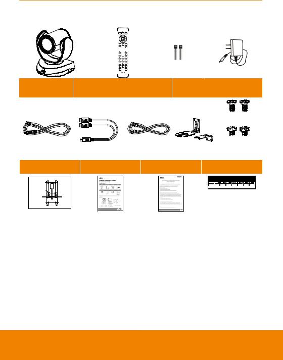
Package Contents
|
Camera Unit1 |
|
Remote Control |
|
AAA Batteries |
|
Power Adapter |
|
|||||||
|
|
|
|
Power Plug |
|
||||||||||
|
|
|
|
|
|
|
|
|
|
|
|
|
|
|
|
|
|
|
|
|
|
|
|
|
|
|
|
|
|
|
|
|
|
|
|
|
|
|
|
|
|
|
|
|
|
|
|
|
|
|
|
|
|
|
|
|
|
|
|
|
|
|
|
|
|
|
|
|
|
|
|
|
|
|
|
|
|
|
|
|
|
|
|
|
|
|
|
|
|
|
|
|
|
|
|
|
|
|
|
|
|
|
|
|
|
|
|
|
|
|
|
|
|
|
|
|
|
|
|
|
|
|
|
|
|
|
|
|
RS232 Cable* |
|
L-Mount |
|
|
|
|
|
|
|
|
|
|
|
Screws for |
|
|
||||||||||||||||||
USB 3.0 Cable |
(mini DIN 9 to |
HDMI Cable* |
|
|
|
|
|
|
|
|
|
|
|
|
|
||||||||||||||||||||
Bracket |
|
|
|
|
|
|
|
|
|
|
|
|
|
|
|
Mount |
|
|
|
|
|
|
|||||||||||||
|
mini DIN8) |
|
|
|
|
|
|
|
|
|
|
|
|
|
|
|
|
|
|
|
|
|
|
||||||||||||
|
|
|
|
|
|
|
|
|
|
|
|
|
|
|
|
|
|
|
|
|
|
|
|
|
|
|
|
|
|
|
|
|
|
|
|
|
|
|
|
|
|
|
|
|
|
|
|
M4 x 8mm(x2) |
|||||||||||||||||||||||
|
|
|
|
|
|
|
|
|
|
|
|
|
|
|
|
|
|
|
1/4”-20 |
|
|
|
|
|
|
||||||||||
|
|
|
|
|
|
|
|
|
|
|
|
|
L=7.5mm(x2) |
||||||||||||||||||||||
Drilling Paper |
Quick Guide |
Warranty Card |
DIP Switch Sticker* |
||||||||||||||||||||||||||||||||
|
|
|
|
|
|
The table below is for HDMI output resolution combination. |
|||||||||||||||||||||||||||||
46.00[1.81] |
|
|
|
Please refer to it while using PDIswitch on the rear panel of camera |
|||||||||||||||||||||||||||||||
|
|
|
|
1 |
2 |
3 |
4 |
1 |
2 |
3 |
4 |
1 |
2 |
3 |
4 |
1 |
2 |
3 |
4 |
1 |
2 |
3 |
4 |
1 |
2 |
3 |
4 |
1 |
2 |
3 |
4 |
1 |
2 |
3 |
4 |
|
|
|
|
|
Auto |
1080P/60 |
1080P/30 |
1080P/50 |
|
|
|
|
720P/60 |
720P/50 |
480P/60 |
||||||||||||||||||||
Ø 5.50[Ø 0.22] |
|
|
|
|
|
|
|
|
|
|
|
|
|
|
|
|
|
|
|
|
|
|
|
|
|
|
|
|
|
|
|
|
|
|
|
P/N: 303AU340-AGR |
51.00[2.01] |
1: There are two SKUs: CAM520 Pro, CAM520 Pro(PoE). CAM520 Pro(PoE) SKU supports HDMI port, DIP switch and PoE+ function.
2: The power plug will vary depending on the standard power outlet of the country where it is sold. * Included with CAM520 Pro(PoE) SKU
1

Product Introduction
Overview
1
2
1Status LED
2IR sensor
3DIP switch1
3 |
4 |
5 |
6 |
7 |
8 |
9 |
4 |
HDMI port1 |
7 |
DC 12V power plug |
5 |
USB3.1 Type B port |
8 |
Ethernet port2 |
6 |
RS232 in/out port |
9 |
Kensington Lock |
1: Only supports for CAM520 Pro(PoE) SKU.
2: CAM520 Pro supports LAN. CAM520 Pro(PoE) SKU supports PoE+(IEEE 802.3AT).
DIP Switch
[Only supports CAM520 Pro(PoE) SKU]
The diagram below shows the DIP Switch configurations which can be used to adjust the camera resolution setting.
After adjusting the resolution via DIP switch, users will be unable to adjust the resolution setup from OSD menu using the remote control.
2

Remote Control
|
Name |
|
Function |
|
|
|
|
||
|
|
|
|
|
|
1. Camera select |
One remote can control up to 3 AVer |
||
|
|
|
VC/CAM/VB series cameras. You can |
|
|
|
|
use AVer PTZApp to set numbers |
|
|
|
|
associated with each camera, and |
|
|
|
|
then select which camera you would |
|
|
|
|
like to control using the remote. |
|
|
|
|
[Note] If you only have one camera |
|
|
|
|
that requires no additional setting, the |
|
|
|
|
default is camera 1. |
|
|
|
|
If camera 2 or 3 is selected, the |
|
|
|
|
remote will be unable to control the |
|
|
|
|
camera. In this case, please press |
|
|
|
|
camera 1 on your remote. |
|
|
|
|
|
|
2.Camera directional control
Use the directional buttons on the remote to control the direction of the camera. Press the directional button to move the camera or press and hold to continuously pan or tilt.
3. |
SmartFrame |
One-click automatic FOV adjustment |
||||
|
|
to fit all participants. |
|
|||
|
|
|
|
|
|
|
|
|
Press and hold |
|
|
|
on the remote |
|
|
|
|
|
||
|
|
|
|
|
||
|
|
for 2 seconds to switch the |
||||
|
|
SmartFraming function between auto |
||||
|
|
and manual mode; a message (as |
||||
|
|
figure shown) will display on the |
||||
|
|
screen to indicate auto or manual |
||||
|
|
mode. |
|
|||
|
|
[Note] While in the video conference |
||||
|
|
meeting, participants must face the |
||||
|
|
camera for proper face detection |
||||
|
|
(SmartFrame). Side facial profiles are |
||||
|
|
not detectable. |
|
|||
|
|
|
||||
4. |
OSD menu |
To call out OSD menu. Only supports |
||||
|
|
CAM520 Pro(PoE) SKU while |
||||
|
|
connecting HDMI output to TV |
||||
|
|
monitor. |
|
|||
|
|
|
|
|
|
|
3

*Function requires AVer PTZApp
**Not supported for CAM520 Pro and CAM520 Pro(PoE)
|
|
|
5. |
Zoom in/Zoom out |
Increase/Decrease the camera zoom. |
|
|
|
|
|
|
6. |
Preset |
1. To save the camera at the desired |
position, press and hold the preset button until the "saved message" is displayed on the PTZApp video screen or other video apps. Select preset position button 0 to 9 to save.
2. Press “preset” + “preset position button” (0~9) to move the camera to the saved position.
7.Preset position/Number buttons
Preset position buttons are used in conjunction with the Preset button to save positions. There are a total of 10 presets.
Press the preset button first and then press 0~9 for the camera to move to
the saved position.
[Note]
Press and hold the number button “ 

 ” to turn the WDR function on or off.
To turn off SmartFrame function, Press and hold number button
“

 ”for one second to switch the function off or on.
8. |
Brightness - |
Decrease the brightness. |
|
|
|
9. |
Call/answer* |
Answer a call or start a call. |
|
|
|
10. |
Enter** |
To confirm selection. |
|
|
|
11. |
Mute/Unmute |
Mute/Unmute the speakerphone. |
|
Speakerphone** |
|
|
|
|
|
|
|
12. |
Volume up/down** |
Adjust volume up or down. |
|
|
|
|
|
|
13. |
Preset hot key |
Press to move the camera to the |
|
|
preset position the user has set. |
|
|
|
14. |
Brightness + |
Increase the brightness. |
|
|
|
15. |
Hang up* |
End the call. |
|
|
|
4

Pan and Tilt Angle
5

Installation
Device Connection
1.Use USB cable to connect the CAM520 Pro to your PC/laptop (refer to diagram above).
2.Connect the power to the CAM520 Pro; power indicator will light up and camera head will rotate.
3.Install AVer PTZApp on laptop or PC that is connected with CAM520 Pro. The app can be used to adjust and setup the parameters of the camera (refer to the section of AVer PTZApp)
4.To make a call, run your video application (Zoom, Microsoft® Teams, Skype for Business, Skype,
Google Hangouts, Intel® Unite™, RingCentral, BlueJeans, V-Cube, LiveOn, CyberLink U Meeting® , TrueConf, Adobe Connect, Cisco WebEx® , Fuze, GoToMeeting™, Microsoft® Lync™,
Vidyo, vMix, WebRTC, Wirecast, XSplit.… etc.) select CAM520 Pro as your video device.
6

Power Connection
The power supply can be plugged into the wall outlet or drawn from PoE+ switch (Ethernet).
[PoE+ is only supported for Advanced model.] Wall outlet
PoE+
[Note]
a.To ensure stability of IP video streaming, please use CAT 5e FTP cable (not included).
b.For PoE switch hub, it’s recommended to use Gigabit PoE switch to ensure stable power supply.
7
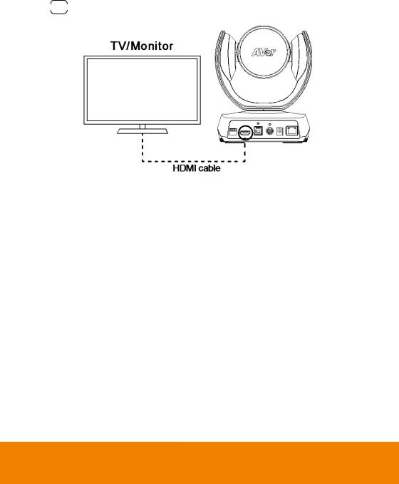
HDMI Connection
[HDMI connection is only supported for CAM520 Pro(PoE) SKU.]
Connect with TV or monitor through the HDMI port to display camera video on the screen.
Press 

 button on remote control to call out the OSD menu to configure the parameters of the camera. For OSD setting refer to OSD operation section.
8
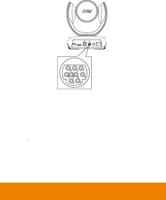
RS232 Connection
Camera RS232 Port Pin Definition
Function |
|
Mini DIN9 |
|
I/O Type |
|
Signal |
|
|
Description |
|
||
|
PIN # |
|
|
|
|
|
||||||
|
|
|
|
|
|
|
|
|
|
|
|
|
|
|
|
|
|
|
|
|
|
|
|
|
|
|
|
1 |
|
Output |
|
DTR |
|
Data Terminal Ready |
||||
|
|
|
|
|
|
|
|
|
|
|
||
|
|
2 |
|
Input |
|
DSR |
|
Data Set Ready |
||||
VISCA IN |
|
|
|
|
|
|
|
|
|
|
|
|
|
|
|
|
|
|
|
|
|
|
|
||
|
|
3 |
|
Output |
|
TXD |
|
Transmit Data |
|
|
||
|
|
|
|
|
|
|
|
|
||||
|
|
|
|
|
|
|
|
|
|
|
|
|
|
|
6 |
|
Input |
|
RXD |
|
Receiver Data |
|
|||
|
|
|
|
|
|
|
|
|
||||
|
|
7 |
|
Output |
|
DTR |
|
Data Terminal Ready |
||||
|
|
|
|
|
|
|
|
|
|
|
||
|
|
4 |
|
Input |
|
DSR |
|
Data Set Ready |
||||
|
|
|
|
|
|
|
|
|||||
|
|
|
|
|
|
|
|
|
|
|
|
|
VISCA OUT |
8 |
|
Output |
|
TXD |
|
Transmit Data |
|
||||
|
|
|
|
|
|
|
|
|
||||
|
|
|
|
|
|
|
|
|
|
|
|
|
|
|
9 |
|
Input |
|
RXD |
|
Receiver Data |
|
|||
|
|
|
|
|
|
|
|
|
|
|||
|
|
5 |
|
--- |
|
--- |
|
|
Not connect |
|||
|
|
|
|
|
|
|
|
|
|
|
|
|
9

Computer/Keyboard Controller and Camera Connection
Direct Connection
If users don’t buy AVer RS232 adaptor cable, please refer to the pin connection shown below.
|
Camera |
|
Controller/PC |
|
(Mini DIN9) |
|
|
(DB9) |
|
|
|
|
|
|
1. |
DTR(IN) |
1. |
DCD |
|
2. |
DSR(IN) |
2. |
RXD |
|
3. TXD(IN) |
|
3. TXD |
||
6. |
RXD(IN) |
4. |
DTR |
|
7. DTR(OUT) |
|
5. GND |
||
4. |
DSR(OUT) |
6. |
DSR |
|
8. TXD(OUT) |
7. |
RTS |
||
9. |
RXD(OUT) |
8. |
CTX |
|
|
|
9. |
RI |
|
10
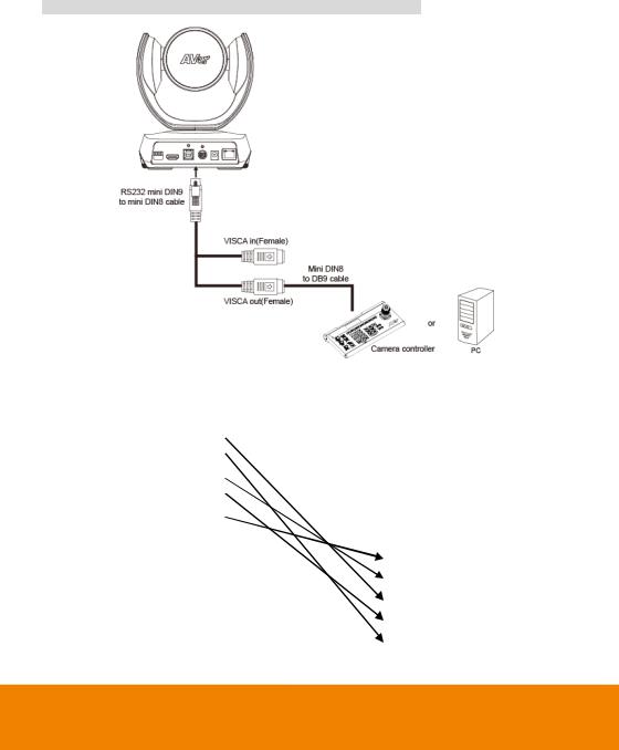
Use the RS232 mini DIN9 to mini DIN8 cable (included with CAM520 Pro(PoE) SKU, otherwise sold separately).
Users can purchase AVer RS232 min DIN9 to mini DIN8 adaptor cable* to connect with Computer or keyboard/controller.
* RS232 (mini DIN9 to mini DIN8) adaptor cable (PN: 064AOTHERCDC)
Controller/PC |
|
|
|
Camera |
||||||
|
(DB9) |
|
(Mini DIN8) |
|||||||
|
|
|
|
|
|
|
|
|
|
|
1. |
DCD |
1. |
DTR(IN) |
|||||||
|
|
|
|
|
|
|
|
|
||
2. |
RXD |
|
|
2. |
DSR(IN) |
|||||
|
|
|
|
|
|
|
|
|||
3. |
TXD |
|
|
|
3. TXD(IN) |
|||||
|
|
|
|
|
|
|
|
|||
4. |
DTR |
|
|
4. |
GND(IN) |
|||||
|
|
|
|
|
|
|
||||
5. |
GND |
|
5. |
RXD(IN) |
||||||
|
|
|
|
|
|
|
||||
6. |
DSR |
|
6. |
GND(IN) |
||||||
7. |
RTS |
|
|
|
|
|
|
|||
|
|
|
|
|
|
|
||||
8. |
CTX |
1. |
|
DTR(OUT) |
|
|
||||
|
|
|
|
|
|
|
||||
9. |
RI |
2. |
|
DSR(OUT) |
|
|
||||
|
|
|
|
|
|
|
|
|||
|
|
|
|
|
|
3. |
TXD(OUT) |
|
|
|
|
|
|
|
|
|
|
||||
|
|
|
|
|
|
4. |
GND(OUT) |
|
||
|
|
|
|
|
|
|
|
|||
|
|
|
|
|
5. |
|
RXD(OUT) |
|
||
|
|
|
|
|
|
6. GND(OUT) |
||||
11
RS232 mini DIN9 to mini DIN8 Cable Pin Definition
Mini DIN9
 Connect to AVer camera
IN(Mini DIN8)
 Connect to next camera
 Connect to controller or PC
OUT(Mini DIN8)
Mini DIN8 Pin Definition
|
No. |
|
|
Pin |
|
|
|
|
|
||
|
|
|
|
|
|
1 |
|
|
DTR |
||
|
|
|
|
||
2 |
|
|
DSR |
||
|
|
|
|
||
3 |
|
|
TXD |
||
|
|
|
|
||
4 |
|
|
GND |
||
|
|
|
|
||
5 |
|
|
RXD |
||
|
|
|
|
||
6 |
|
|
GND |
||
|
|
|
|
||
7 |
|
|
NC |
||
|
|
|
|
||
8 |
|
|
NC |
||
|
|
|
|
|
|
12

Camera Cascade Connection
Direct Connection
If users don’t buy AVer RS232 adaptor cable, please refer to the pin connection shown below for cascading cameras.
Total can connect up to 7 cameras.
|
Camera 1 |
|
|
Camera 2 |
(Mini DIN9) |
|
(Mini DIN9) |
||
|
|
|
|
|
1. |
DTR(IN) |
1. |
DTR(IN) |
|
2. |
DSR(IN) |
2. |
DSR(IN) |
|
3. TXD(IN) |
|
3. TXD(IN) |
||
6. |
RXD(IN) |
6. |
RXD(IN) |
|
7. |
DTR(OUT) |
7. |
DTR(OUT) |
|
4. |
DSR(OUT) |
4. |
DSR(OUT) |
|
8. TXD(OUT) |
|
8. TXD(OUT) |
||
9. |
RXD(OUT) |
9. |
RXD(OUT) |
|
SHIELD |
|
SHIELD |
||
13
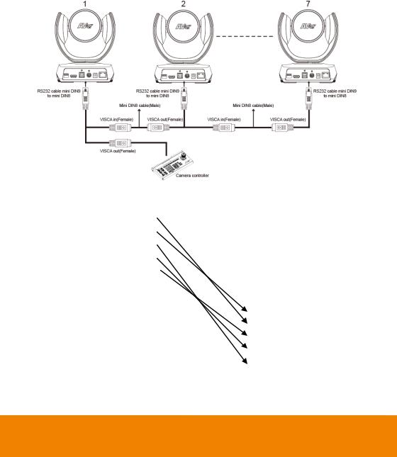
Use the RS232 mini DIN9 to mini DIN8 cable
Total can connect up to 7 cameras.
To facilitate the camera cascade, users can purchase AVer RS232 adaptor cable.
Connect camera with AVer mini DIN9 to mini DIN8 adaptor cable. Connect the mini DIN8 female side to male mini DIN8 Visca cable (Users have to buy it in the market) and then connect AVer mini DIN9 to mini DIN8 adaptor cable again to connect to next camera.
|
|
Camera 1 |
|
|
|
Camera 2 |
|||||||
|
(Mini DIN8) |
|
|
(Mini DIN8) |
|||||||||
|
|
|
|
|
|
|
|
|
|
|
|
|
|
|
1. DTR(IN) |
|
|
1. |
|
DTR(IN) |
|||||||
|
|
|
|
|
|
|
|
|
|
|
|
|
|
|
2. |
|
DSR(IN) |
|
|
2. |
|
DST(IN) |
|||||
|
|
|
|
|
|
|
|
|
|
|
|
||
|
3. |
|
TXD(IN) |
|
|
|
|
3. TXD(IN) |
|||||
|
|
|
|
|
|
|
|
|
|||||
|
4. |
GND(IN) |
|
4. |
|
GND(IN) |
|||||||
|
|
|
|
|
|
|
|
|
|
|
|||
|
5. |
|
RXD(IN) |
|
5. |
|
RXD(IN) |
||||||
|
6. GND(IN) |
6. |
|
GND(IN) |
|||||||||
|
|
|
|
|
|
|
|
|
|||||
|
1. DTR(OUT) |
1. |
|
|
DTR(OUT) |
|
|
||||||
|
|
|
|
|
|
|
|||||||
|
2. DSR(OUT) |
|
2. |
|
DST(OUT) |
|
|
||||||
|
|
|
|
|
|
|
|||||||
|
3. TXD(OUT) |
|
|
3. |
TXD(OUT) |
|
|
||||||
|
|
|
|
|
|
||||||||
|
4. GND(OUT) |
|
|
4. |
GND(OUT) |
|
|||||||
|
|
|
|
|
|
||||||||
|
5. RXD(OUT) |
5. |
|
|
RXD(OUT) |
|
|||||||
|
6. GND(OUT) |
|
|
6. GND(OUT) |
|||||||||
14

Wall Mount Installation
1.Use the drilling paper included in the package to drill the holes in the wall where the user wants to mount the camera.
 46.00[1.81]
Ø 5.50[Ø 0.22]
P/N: 303AU340-AGR |
|
|
|
51.00[2.01] |
|
|
2. Use the screw to secure the A L-mount bracket on the wall.
Screw
For Cement wall: M4 x20mm self-tapping screws(x4) + Plastic conical anchor
For Wooden wall: M4 x20mm self-tapping screws(x4)
15
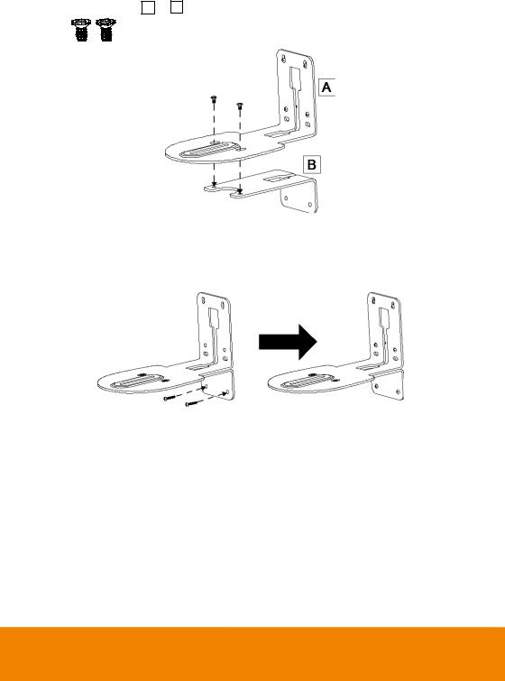
3. Then, assemble the A + B L-mount bracket with screws (included in package).
Screw: |
M4 x 8mm(x2) |
4. After assembling the L-mount bracket, secure the lower part of L-mount bracket on the wall.
Screw
For Cement wall: M4 x20mm self-tapping screws(x2) + Plastic conical anchor
For Wooden wall: M4 x20mm self-tapping screws(x2)
16

5.Pass the cables through the hole on the L-mount bracket and connect the cables to corresponding connection ports.
6. Use the remaining screws (included in package) to secure the camera on the L-mount bracket.
Screw: 


 1/4”-20 L=7.5mm(x2)
17
Loading...