


System 10 PRO
Audio Technica System 10 PRO, ATW-1301/L, ATW-1302, ATW-1311, ATW-1311/L Installation And Operation Manual
...
System 10 PRO
Digital Wireless System
Installation and Operation
ATW-1301
UniPak® Transmitter System
ATW-1301/L
Lavalier Microphone System
ATW-1302
Handheld Microphone System
ATW-1311
Dual UniPak® Transmitter System
ATW-1311/L
Dual Lavalier Microphone System
ATW-1312
UniPak®/Handheld Combo System
ATW-1312/L
Lavalier/Handheld Combo System
ATW-1322
Dual Handheld Microphone System

2
System 10 PRO Installation and Operation
CAUTION
RISK OF ELECTRIC SHOCK
DO NOT OPEN
WARNING: TO REDUCE THE RISK OF FIRE OR ELECTRIC SHOCK, DO NOT REMOVE SCREWS.
NO USER-SERVICEABLE PARTS INSIDE.REFER SERVICING TO QUALIFIED SERVICE PERSONNEL.
WARNING: TO REDUCE THE RISK OF FIRE OR ELECTRIC SHOCK, DO NOT EXPOSE THE
APPLIANCE TO RAIN OR MOISTURE.
CERTIFICATION: THIS DEVICE COMPLIES WITH PART 15 OF THE FCC RULES. THIS DEVICE
COMPLIES WITH INDUSTRY CANADA LICENSE-EXEMPT RSS STANDARD(S). OPERATION IS
SUBJECT TO THE FOLLOWING TWO CONDITIONS: (1) THIS DEVICE MAY NOT CAUSE HARMFUL
INTERFERENCE, AND (2) THIS DEVICE MUST ACCEPT ANY INTERFERENCE RECEIVED,
INCLUDING INTERFERENCE THAT MAY CAUSE UNDESIRED OPERATION.
Cet appareil est conforme à la/aux norme(s) CNR exempte(s) de licence d’Industrie Canada.
Son fonctionnement est soumis aux deux conditions suivantes : (1) cet appareil ne doit pas
causer d’interférence et (2) cet appareil doit accepter toutes les interférences, y compris celles
susceptibles de provoquer un fonctionnement non souhaité.
Under Industry Canada regulations, this radio transmitter may only operate using an antenna of
a type and maximum (or lesser) gain approved for the transmitter by Industry Canada. To reduce
potential radio interference to other users, the antenna type and its gain should be so chosen
that the equivalent isotropically radiated power (e.i.r.p.) is not more than that necessary for
successful communication.
Conformément à la réglementation d'Industrie Canada, le présent émetteur radio peut
fonctionner avec une antenne d'un type et d'un gain maximal (ou inférieur) approuvé pour
l'émetteur par Industrie Canada. Dans le but de réduire les risques de brouillage radioélectrique
à l'intention des autres utilisateurs, il faut choisir le type d'antenne et son gain de sorte que la
puissance isotrope rayonnée équivalente (p.i.r.e.) ne dépasse pas l'intensité nécessaire à
l'établissement d'une communication satisfaisante.
WARNING: Changes or modications not expressly approved in writing by Audio-Technica may
void the user’s authority to operate this equipment.
RF Exposure Statement: This transmitter must not be co-located or operated in conjunction
with any other antenna or transmitter used in other systems.
The ATW-T1001, ATW-T1002 and ATW-RU13 complies with FCC/IC radiation exposure limits
set forth for an uncontrolled environment and meets the FCC radio frequency (RF) Exposure
Guidelines and RSS-102 of the IC radio frequency (RF) Exposure rules. This equipment has
very low levels of RF energy that it deemed to comply without maximum permissive exposure
evaluation. (MPE). But it is desirable that it should be installed and operated keeping the
radiator at least 20cm or more away from person’s body.
Le ATW-T1001, ATW-T1002 et ATW-RU13 conformes aux limites d’exposition aux
rayonnements énoncées pour un environnement non contrôlé et respecte les règles
d’exposition aux fréquences radioélectriques (RF) CNR-102 de l’IC. Cet équipement émet une
énergie RF très faible qui est considérée conforme sans évaluation de l ’exposition maximale
autorisée. Cependant, il est souhaitable qu'il devrait être installé et utilisé en gardant une
distance de 20 cm ou plus entre le dispositif rayonnant et le corps.
Note: The ATW-RC13 has been tested and found to comply with the limits for a Class B digital
device, pursuant to part 15 of the FCC Rules. These limits are designed to provide reasonable
protection against harmful interference in a residential installation. This equipment
generates, uses and can radiate radio frequency energy and, if not installed and used in
accordance with the instructions, may cause harmful interference to radio communications.
However, there is no guarantee that interference will not occur in a particular installation. If
this equipment does cause harmful interference to radio or television reception, which can be
determined by turning the equipment off and on, the user is encouraged to try to correct the
interference by one or more of the following measures:
- Reorient or relocate the receiving antenna.
- Increase the separation between the equipment and receiver.
- Connect the equipment into an outlet on a circuit different from that to which the
receiver is connected.
- Consult the dealer or an experienced radio/TV technician for help.
This Class B digital apparatus complies with Canadian ICES-003. Cet appareil umerique de la
classe B est conforme a la norme NMB-003 du Canada.
CAUTION! Electrical shock can result from removal of the receiver chassis cover. Refer
servicing to qualied service personnel. No userserviceable parts inside. Do not expose
to rain or moisture. The circuits inside the chassis, receivers and transmitters have been
precisely adjusted for optimum performance and compliance with federal regulations. Do not
attempt to open the chassis, receivers or transmitters. To do so will void the warranty, and
may cause improper operation.
Notice to individuals with implanted cardiac pacemakers or AICD devices: Any
source of RF (radio frequency) energy may interfere with normal functioning of the implanted
device. All wireless microphones have low-power transmitters (less than 0.05 watts output)
which are unlikely to cause difculty, especially if they are at least a few inches away.
However, since a “body-pack” mic transmitter typically is placed against the body, we suggest
attaching it at the belt, rather than in a shirt pocket where it may be immediately adjacent
to the medical device. Note also that any medical-device disruption will cease when the RF
transmitting source is turned off. Please contact your physician or medical-device provider
if you have any questions, or experience any problems with the use of this or any other RF
equipment.
Important Safety Instructions
1. Read these instructions.
2. Keep these instructions.
3. Heed all warnings.
4. Follow all instructions.
5. Do not use this apparatus near water.
6. Clean only with a dry cloth.
7. Install in accordance with the manufacturer’s instructions.
8. Do not install near any heat sources such as radiators, heat registers, stoves, or other
apparatus (including ampliers) that produce heat.
9. Unplug this apparatus during lightning storms or when unused for long periods of time.
10. Refer all servicing to qualied service personnel. Servicing is required when the
apparatus has been damaged in any way, such as power-supply cord or plug is damaged,
liquid has been spilled or objects have fallen into the apparatus, the apparatus has been
exposed to rain or moisture, does not operate normally, or has been dropped.
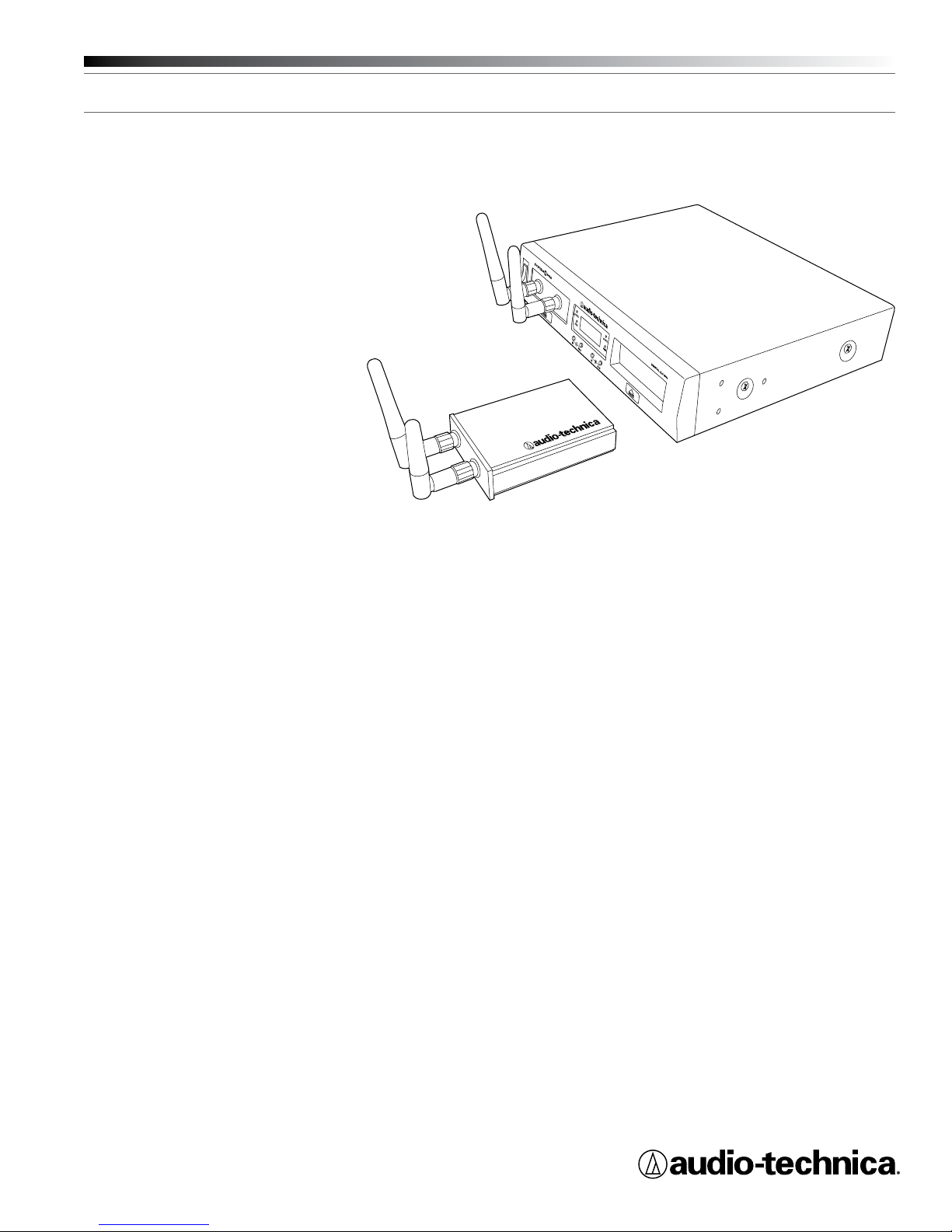
Thank you for choosing an Audio-Technica System 10 PRO Rack-Mount
digital wireless system. You have joined thousands of other satised
customers who have chosen our products because of their quality,
performance and reliability. This wireless microphone system is the
successful result of years of design and manufacturing experience.
Audio-Technica’s System 10 PRO Rack-Mount is a digital wireless
system designed to provide rock-solid performance along with easy
setup and clear, natural sound quality. Featuring a dual-receiver chassis
and remote-mount receiver unit capability, System 10 PRO Rack-Mount
is available in various handheld and body-pack congurations. Operating
in the 2.4 GHz range, far from TV and DTV interference, System 10
PRO Rack-Mount offers extremely easy operation and instantaneous
channel selection. Up to ten channels may be used together without
any frequency coordination problems or group selection issues.
System 10 wireless ensures clear communications by providing three
levels of diversity assurance: frequency, time, and space. Frequency
Diversity sends the signal on two dynamically allocated frequencies
for interference-free communication. Time Diversity sends the signal
in multiple time slots to maximize immunity to multi-path interference.
Finally, Space Diversity uses two antennas on each transmitter and
receiver to maximize signal integrity.
Each conguration of the System 10 PRO digital wireless system
includes a rack-mountable receiver chassis with two receiver unit
docks. Depending on the conguration, the system will also include
one or two receiver units that may be docked in the chassis or
mounted remotely, and one or two transmitters of either the handheld
microphone or body-pack style (or one of each). Some congurations
also include one or two lavalier mics that attach to the body-pack
transmitters. Up to ve chassis (10 receiver units) can be linked with the
included RJ12 cable to allow for simultaneous use of all receivers and
increased stability of the multi-channel system.
Because System 10 packaging is designed to hold all versions of
the system, some compartments in the carton may be intentionally
left empty.
The ATW-R1300 includes a switching power supply that automatically
adapts to changes in mains voltage.
The versatile ATW-T1001 UniPak® body-pack transmitter has both a highimpedance input for instruments, and a low-impedance input with bias
connection for use with dynamic and electret condenser microphones.
The ATW-T1002 handheld transmitter features a unidirectional dynamic
microphone element.
Both the body-pack and handheld transmitters use internal AA batteries
and have Power/Mute switches and input Trim (level) adjustments.
System 10 PRO Installation and Operation
3
Installation
Receiver Unit Location
For best operation, position receiver unit so it is off the oor, in line of
sight of transmitter and away from any large obstructions. Keep the
receiver unit away from noise sources such as other digital wireless
equipment, microwave ovens, as well as away from large metal objects.
Keep System 10 receivers 30' (9 m) away from wireless access points.
Output Connection
The ATW-R1300 is equipped with two audio outputs for each receiver:
a balanced XLR-type output and an unbalanced ¼" TRS phone jack. Use
shielded audio cable for the connection between the receiver and the
mixer. If the input of the mixer is a ¼" jack, connect a cable from the
¼" unbalanced audio output on the back of the receiver chassis to the
mixer. If the input of the mixer is an XLR-type input, connect a cable
from the balanced XLR-type audio output on the back of the chassis to
the mixer.
Power Connection
Connect the DC plug on the included AC power adapter to the DC
power input on the back of the receiver chassis. Secure the cord over
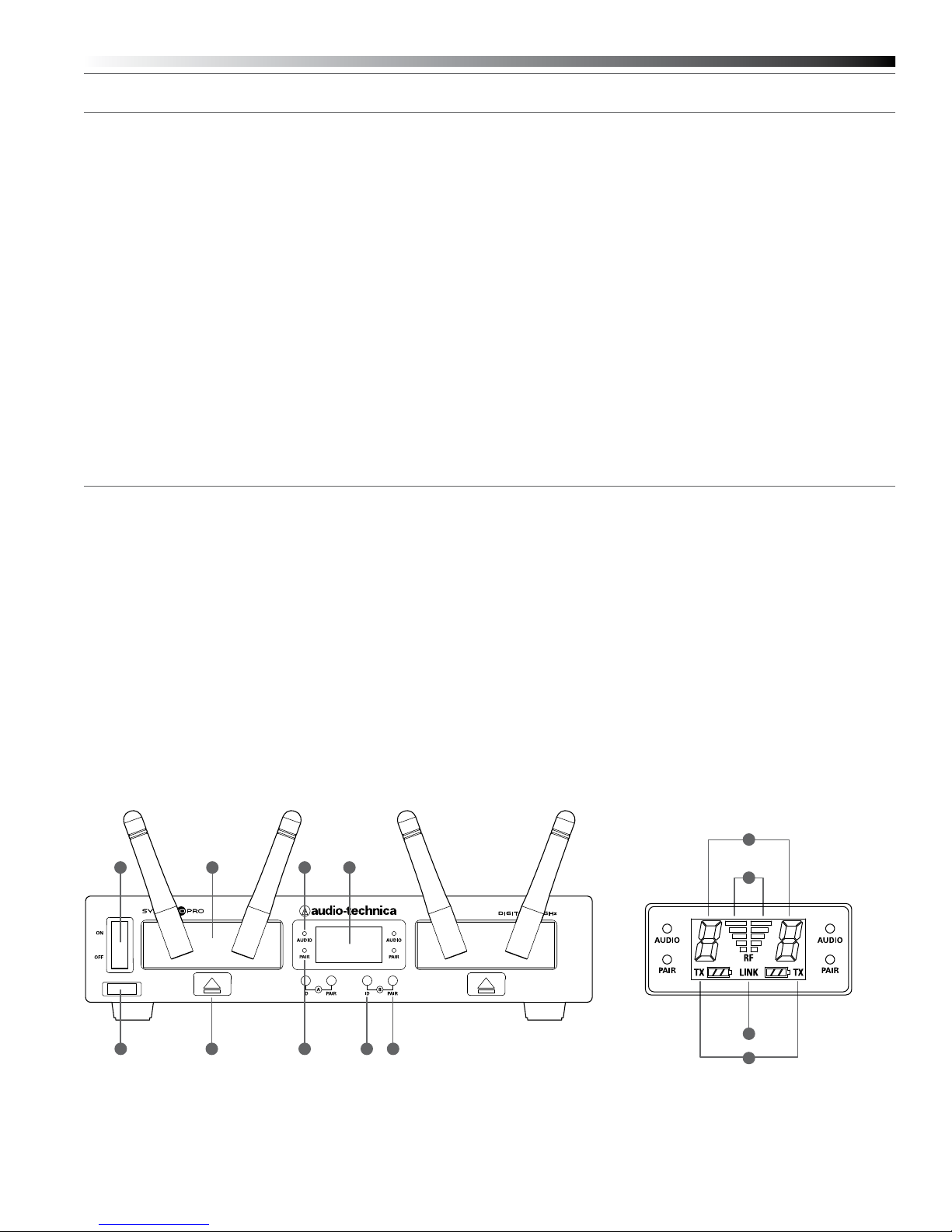
ATW-RC13 Receiver Chassis Controls and Functions
Figure A — Front Panel Controls and Functions
1. Power Switch: Press to turn power on and off.
2. Service Port: For use only by manufacturer or other qualied
service technician.
3. Receiver Unit Docks: Insert individual receivers to use them locally.
4. Receiver Unit Releases: Press to eject receivers.
5. Audio Indicator (one for each receiver): Illuminates green when
sound is received from transmitter, yellow when audio is nearing
peak level, and red when peak level is reached.
6. Pairing Indicator (one for each receiver): Flashes green in pair mode;
illuminates solidly green once transmitter is paired.
7. System ID Select Switch (one for each receiver): Press to cycle
through System ID numbers. (System ID is a shared number
assigned to a paired receiver and transmitter for identication
purposes.)
the cord hook on the chassis to keep the plug from being accidentally
dislodged. Plug the adapter into a standard 120 Volt 60 Hz AC power
outlet. The receiver chassis is equipped with a power On/Off switch.
Turn the power off when system is not in use, and unplug the power
supply if you expect not to use the system for an extended period.
Antennas
For best reception, position the removable antennas in the shape of a
“V” so that both tilt 45°.
Link Connection
When using multiple systems together it is strongly recommended
that you link all of the chassis (up to ve) using the RJ12 cable included
with each system. (Linking is not necessary if you are using only a
single chassis.) Linking creates a much more stable environment in
which receivers work together, with all receiving, transmitting and
frequency allocation coordinated to prevent audio dropouts and enable
simultaneous use of up to 10 channels. See “Linking Systems” on page
9 for more details.
8. Pairing Switch (one for each receiver): Press to initiate pairing.
9. System ID Display includes the following:
a. RF Signal Level Indicator (one for each receiver): Shows strength
of the RF signal received from the transmitter
b. System ID (one for each receiver): Shows the System
ID number
c. Transmitter Battery Gauge TX (one for each receiver): Shows
the capacity of the transmitter’s batteries
d. Link Indicator: Shows that the chassis has been linked to
another chassis
Figure A
5
2
4
6 7 8
b
931
a
d
c
4
System 10 PRO Installation and Operation
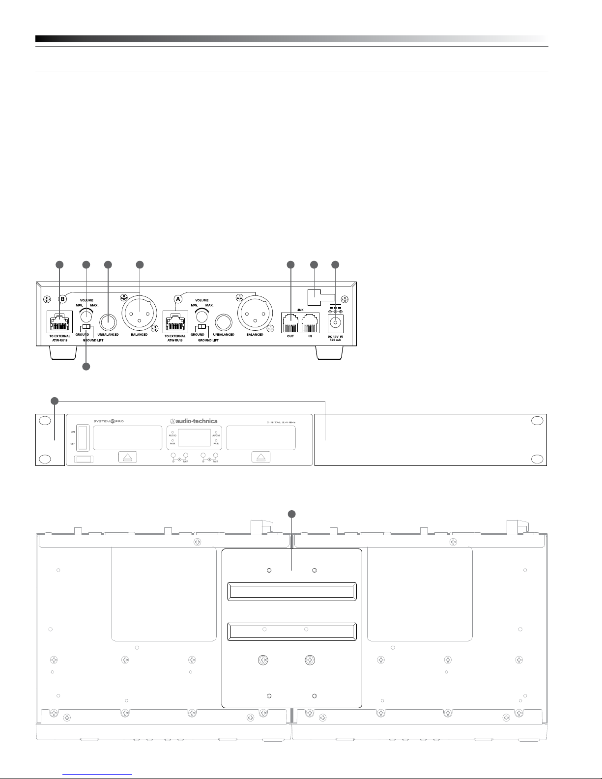
Figure B, C & D — Rear Panel Controls and Functions
1. RJ45 Connector: Use Ethernet cable (not included) to mount
receiver remotely up to 328' (100 m) from chassis.
2. AF Level (Volume) Control: Adjusts audio output level of both AF
output jacks; maximum output is fully clockwise.
3. Ground Lift Switch: Disconnects the ground pin of the balanced
output jack (5) from ground. Normally, the switch should be to the
left (ground connected). If hum caused by a ground loop occurs,
slide switch to the right (ground lifted).
4. Unbalanced Audio Output Jack: ¼" phone jack. Can be connected
to an unbalanced aux-level input of a mixer, guitar amp or recording
device.
5. Balanced Audio Output Jack: XLRM-type connector. A standard
2-conductor shielded cable can be used to connect the receiver
output to a balanced microphone-level input on a mixer or
integrated amplier.
Figure B
5
6. Receiver Chassis Link IN/OUT Connector: Use included RJ12 cable
to link chassis to another ATW-R1300 chassis. Up to ve chassis (10
receivers) may be linked.
7. Cord Hook: Loop the cord around the cord hook to keep the DC plug
from pulling loose accidentally.
8. Power Input Jack: Connect the DC plug from the included
AC adapter.
9. Rack Mounting Brackets: Attach brackets to the sides of the receiver
chassis using supplied screws.
10. Joining Plate: Attach to the bottom of two receiver chassis using
supplied screws.
6 7 8421
3
Figure C — Rack Mounting Brackets
9
Figure D — Joining Plate
10
 Loading...