


AT895
Adaptive-array Microphone Systems
New Technology Enhances Audio Acquisition
Unique, groundbreaking optimization of acoustic, analog and digital design produces unmatched directional performance, operating versatility and ease of use.
AT895/MK
Mount Kit
AT895/RK
Remote Kit
Installation and Operation

AT895 Adaptive-array Microphone Systems
Installation and Operation
Warning: Changes or modifications to this unit not expressly approved by the party responsible for
compliance could void the user’s authority to operate the equipment.
Introduction
Thank you for choosing an AT895 Adaptive-array Microphone System. AT895 Systems incorporate a revolutionary DSPcontrolled five-element microphone array that provides adaptive directional audio acquisition.
Note: This equipment has been tested and found to comply with the limits for a Class B digital device, pursuant to Part 15 of the FCC rules. These limits are designed to provide reasonable protection against harmful interference in a residential installation. This equipment generates, uses, and can radiate radio frequency energy and, if not installed and used in accordance with the instructions, may cause harmful interference to radio communications. However, there is no guarantee that interference will not occur in a particular installation. If this equipment does cause harmful interference to radio or television reception, which can be determined by turning the equipment off and on, the user is encouraged to try to correct the interference by one or more of the following measures:
•Reorient or relocate the receiving antenna.
•Increase the separation between the equipment and the receiver.
•Connect the equipment into an outlet on a circuit different from that to which the receiver is connected.
•Consult the dealer or an experienced radio TV technician for help.
Utilizing Audio-Technica’s proprietary DeltaBeam™ technology, the AT895 System manipulates and filters the output of the array by acoustical, analog and digital means. This process enhances the pickup of a sound source from a desired direction relative to unwanted background noise or interference, providing cancellation of up to 80 dB. Other benefits include minimized audibility of proximity effect, minimized nearfield effect on the low-frequency directionality of the array, and markedly reduced susceptibility to mechanical noise, wind noise and racking as compared to currently-available professional microphones.
The AT895 functions equally well for handheld interview use or long-range sound pickup – in the field, in the studio, or in security operations.
AT895 vs. Typical Shotgun Performance†
Compare acceptance angles (at 3 dB down): |
|
|
|
|
|
|
|||
Microphone |
200 Hz |
400 Hz |
1 kHz |
2 kHz |
4 kHz |
8 kHz |
|||
Shotgun |
60˚ |
60˚ |
60˚ |
50˚ |
30˚ |
20˚ |
|||
AT895 |
20˚ |
20˚ |
20˚ |
20˚ |
60˚ |
50˚ |
|||
Compare polar patterns at 200 Hz: |
|
|
|
Compare maximum off-axis rejection: |
|
|
|||
Microphone |
200 Hz Rejection at 90˚/270˚ |
|
Microphone |
|
Maximum Off-axis Rejection |
||||
Shotgun |
15 dB |
|
|
|
Shotgun |
|
30 dB |
|
|
AT895 |
70 dB |
|
|
|
AT895 |
|
80 dB |
|
|
† Compared to typical performance of a professional-quality 15.5" line + gradient microphone (measurement conditions: 1Pa at 0.5 m). Due to the adaptive nature of its digital processing, AT895 performance in actual field conditions will vary with the environment encountered.
Incorporated in the AT895 design are: DSDA-PRO™ software (U.S. Patent No. 5,825,898) by Lamar Signal Processing, Ltd., a wholly-owned subsidiary of Andrea Electronics Corporation; DeltaBeam™ (U.S. Patent pending) and MicroLine® technologies by Audio-Technica. “DSDA-PRO” is a trademark of Lamar Signal Processing, Ltd.; “DeltaBeam” is a trademark of and “MicroLine” is a registered trademark of Audio-Technica.
2
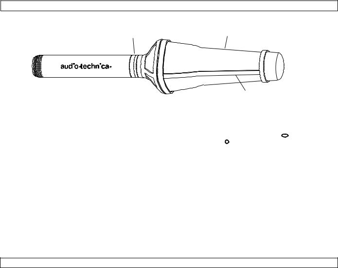
The Basic System
|
Model No. |
No ribs |
|
on “Top” |
|
|
“AT895” |
|
|
and “Bottom” |
|
|
at “Top” |
|
|
|
|
|
|
|
|
|
|
Fig. A AT895 Microphone
AT895 Microphone
The AT895 Microphone itself is “all analog,” housing one Audio-Technica MicroLine® element, four A-T cardioid elements mounted in a co-planar diamond configuration, and five mic preamps. The five amplified analog signals from the microphone elements are sent individually down a special detachable cable to the AT895CP Control Pack.
AT895CP Control Pack
The AT895CP Control Pack provides all the power, Digital Signal Processing, and control for the AT895. Output from the Control Pack is analog at mic-level (–23 dBV).
The lightweight, sturdy metal housing accepts a quick-change, click-on Battery Housing for totally self-contained operation, if desired. The Control Pack also operates on external 12-14V DC — from an Anton/Bauer or similar-type battery source, or from an AC adapter — via an industry-standard 4-pin XLR-type connection.
Ribs on “Sides”
Control features on the AT895CP are:
• Three-position Mode (pickup pattern) switch which provides Full-field Adaptive ( ) Planar-adaptive ( ) and
Line + Gradient ( ) settings. (See page 5 for a full explanation of the Mode settings).
•Audio filter switch with Flat, High-pass and Band-pass settings.
•Monitor headphone jack with volume control.
•LCD battery condition indicator.
•Power switch with LED indicator.
Two System Configurations
The AT895 is available as the AT895/RK “Remote Kit” for field use, and as the AT895/MK “Mount Kit” for studio and fixed-install applications.
AT895/RK Remote Kit includes:
•AT895MIC Adaptive-array Microphone
•AT895CP Control Pack with attached belt clip
•AT895BH Click-on Battery Housing
•AT895PG Pistol-grip shock mount
•AT895Z Zeppelin-type windscreen
•AT895C-10 Special 6-conductor shielded Cable, 10' long
• AT895CC |
Carrying Case |
AT895/MK Mount Kit includes:
• AT895MIC Adaptive-array Microphone
• AT895CP Control Pack
• AT895SC Shock-mount Stand Clamp with 5/8"-27 threaded stud
• AT895PS1 Multi-input AC Power Supply with “120V” IEC detachable power cord
• AT895C-25 Special 6-conductor shielded Cable, 25' long
All components and accessories are interchangeable and available separately to augment systems or to use as “field spares.” In addition, two accessory kits are available:
• AT895CK Conversion Kit adds the components needed for an AT895/MK system to function as an AT895/RK system.
• AT895FBK Fisher Boom Kit permits use of the AT895 on a Fisher boom.
(See page 7 for a complete listing of available system components and accessories.)
The AT895 Microphone and Control Pack are designed to operate as a system only. Do not attempt to use these components with other devices.
3
 Loading...