


AT-LP120XBT-USB
User Manual
Wireless Direct-Drive Turntable

Introduction
Thank you for purchasing this Audio-Technica product.
Before using the product, read through this user manual to ensure that you will use the product correctly. Please keep this manual for future reference.
This product can be used only in the countries where the product is sold. Make sure that the operating voltage and the plug of AC adapter of the product are correct for the country you live in.
Package contents
Make sure that you have all the included items listed below before using this product.
If some items are missing or damaged, contact your local Audio-Technica dealer.
|
• Turntable body |
|
• Dust cover |
|
• Felt mat |
||||||||||
|
|
|
|
|
|
|
|
|
|
|
|
|
|
|
|
|
|
|
|
|
|
|
|
|
|
|
|
|
|
|
|
|
|
|
|
|
|
|
|
|
|
|
|
|
|
|
|
|
|
|
|
|
|
|
|
|
|
|
|
|
|
|
|
|
|
|
|
|
|
|
|
|
|
|
|
|
|
|
|
|
|
|
|
|
|
|
|
|
|
|
|
|
|
|
|
• Platter |
|
• Counterweight |
• Headshell (AT-HS6) with VM stereo |
||||||||||||||||
|
|
|
|
|
|
|
cartridge (AT-VM95E) |
||||||||||||
|
|
|
|
|
|
|
|
|
|
|
|
|
|
|
|
|
|
|
|
|
|
|
|
|
|
|
|
|
|
|
|
|
|
|
|
|
|
|
|
|
|
|
|
|
|
|
|
|
|
|
|
|
|
|
|
|
|
|
|
|
|
|
|
|
|
|
|
|
|
|
|
|
|
|
|
|
|
|
|
|
|
|
|
|
|
|
|
|
|
|
|
|
|
|
|
|
|
|
|
|
|
|
|
|
|
|
|
|
|
|
|
|
|
|
|
|
|
|
|
|
|
|
|
|
|
|
|
|
|
|
|
|
|
|
|
|
|
|
|
|
|
|
|
|
|
|
|
|
|
|
|
|
|
|
|
|
|
|
|
|
|
|
|
|
|
|
|
|
|
|
|
|
|
|
|
|
|
|
|
|
|
|
|
|
|
|
|
|
|
|
|
|
|
|
|
|
|
|
|
• 45 RPM adapter |
• Stylus target light |
• Dust cover hinges |
• AC adapter (approx. 1.3 m (4.3'))
• Quick start guide
• Caution guide
• USB cable (1.9 m (6.2')) |
• RCA audio cable (approx. 1.4 m (4.6')) |
After purchase, we suggest that you save all packaging materials for possible future storage, moving, or shipping.
1

Safety precautions
Although this product was designed to be used safely, failing to use it correctly may result in an accident. To ensure safety, observe all warnings and cautions while using the product.
Important information
Warning:
To prevent fire or shock hazard, do not expose this apparatus to rain or moisture.
Caution:
•Do not expose this apparatus to drips or splashes.
•To avoid electric shock, do not open the cabinet.
•Refer servicing to qualified personnel only.
•Do not expose this apparatus to excessive heat such as sunshine, fire or the like.
•Do not subject this apparatus to strong impact.
•This apparatus should be located close enough to the AC outlet so that you can easily grasp the AC adapter at any time.
•In case of emergency, disconnect the AC adapter quickly.
•Do not place any objects filled with liquids, such as vases, on this apparatus.
•To prevent fire, do not place any naked flame sources (such as lighted candles) on this apparatus.
•Do not install this apparatus in a confined space such as a bookcase or similar unit.
•Install this apparatus only in the place where ventilation is good.
For customers in the USA
FCC Notice
Warning:
This device complies with Part 15 of the FCC Rules. Operation is subject to the following two conditions: (1) This device may not cause harmful interference, and (2) this device must accept any interference received, including interference that may cause undesired operation.
Caution:
You are cautioned that any changes or modifications not expressly approved in this manual could void your authority to operate this equipment.
Note: This equipment has been tested and found to comply with the limits for a Class B digital device, pursuant to part 15 of the FCC Rules. These limits are designed to provide reasonable protection
against harmful interference in a residential installation. This equipment generates, uses and can radiate radio frequency energy and, if not installed and used in accordance with the instructions, may cause harmful interference to radio communications. However, there is no guarantee that interference will not occur in a particular installation. If this equipment does cause harmful interference to radio or television reception, which can be determined by turning the equipment off and on, the user is encouraged to try to correct the interference by one or more of the following measures:
––Reorient or relocate the receiving antenna.
––Increase the separation between the equipment and receiver.
––Connect the equipment into an outlet on a circuit different from that to which the receiver is connected.
––Consult the dealer or an experienced radio/TV technician for help.
Contact:
Responsible Company: Audio-Technica U.S., Inc.
Address: 1221 Commerce Drive, Stow, Ohio 44224, USA
Tel: 330-686-2600
Safety precautions
RF Exposure Statement:
This transmitter must not be co-located or operated in conjunction with any other antenna or transmitter used in other systems. This device complies with FCC radiation exposure limits set forth for an uncontrolled environment and meets the FCC radio frequency (RF) Exposure Guidelines. This equipment has very low levels of RF energy that it deemed to comply without maximum permissive exposure evaluation (MPE). But it is desirable that it should be installed and operated keeping the radiator at least 20 cm or more away from person’s body.
For customers in Canada
IC statement:
CAN ICES-3 (B)/NMB-3(B)
This device complies with INDUSTRY CANADA R.S.S. 247. Operation is subject to the following conditions: (1) This device may not cause harmful interference and (2) this device must accept any interference received, including interference which may cause undesired operation. Under Industry Canada regulations, this radio transmitter may only operate using an antenna of a type and maximum (or lesser) gain approved for the transmitter by Industry Canada. To reduce potential radio interference to other users, the antenna type and its gain should be so chosen that the equivalent isotropically radiated power (e.i.r.p.) is not more than that necessary for successful communication. This equipment should be installed and operated with minimum distance 20 cm between the radiator & your body.
Notes on use
Turntable body
•Do not set and use the product in locations that are considerably hot or humid, dirty, or subject to extreme vibrations.
•The product should be positioned on a flat, level surface.
•Read the user manual for the Bluetooth receiver device.
Cartridge
•Attach the protector to protect the stylus when the product is not in use.
•Do not touch the stylus of the cartridge with your finger.
•Do not allow the cartridge's stylus to bump against the platter or the edge of the record.
2
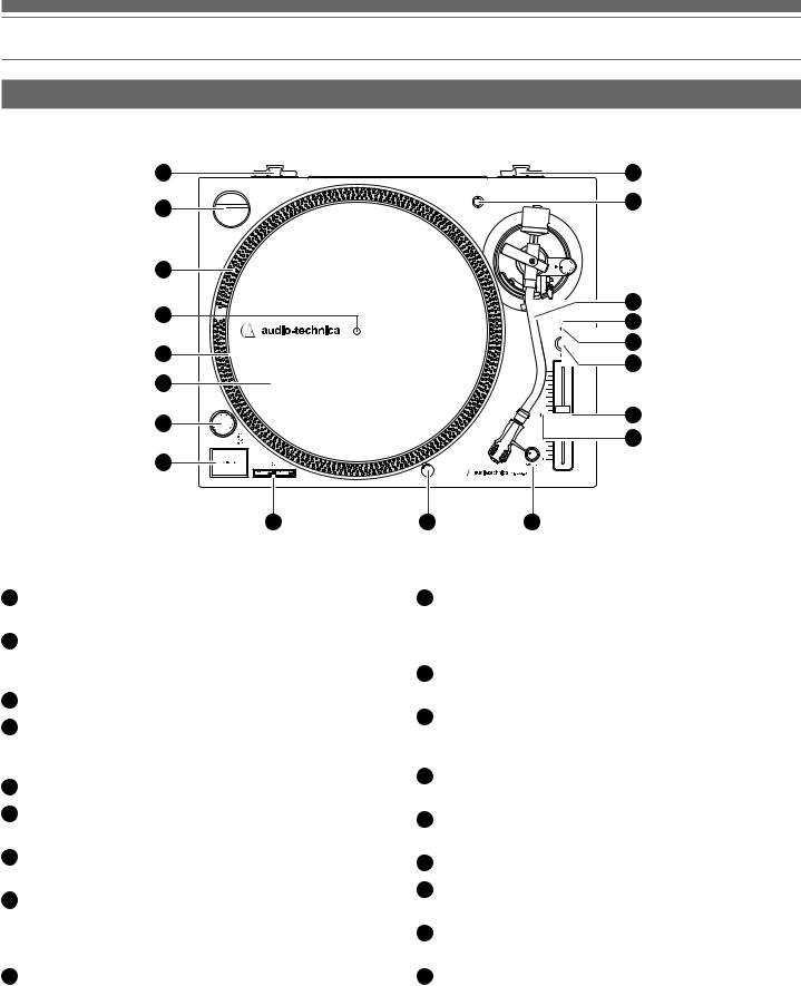
Part names and functions
Top view diagram
18
1
2
3
4
5
6
7
8 |
9 |
18
17
16 |
15 |
14 |
13 |
12
11
10 |
145-RPM adapter (shown in receptacle)
Adapts 7" records with large center holes to fixed center spindle.
2Strobe dots (on platter edge)
Operate in conjunction with stroboscopic light located under the power dial to provide visual indication of accurate platter speeds.
3Spindle
4Platter
Cast aluminum platter mounts directly to center spindle/motor shaft.
5Felt mat
6Power dial
Controls power to the unit.
7START/STOP button
Engages and disengages the motor/platter.
8Platter speed buttons
Select 33 or 45 RPM platter speed. 78 RPM is selected by pressing both the 33 and 45 buttons simultaneously; both buttons should be illuminated.
9Removable stylus target light
Provides illumination directed at the stylus position for easier cueing in low light. Easily plugs into jack on top of turntable deck.
10Quartz button
Turns the pitch function on and off. When the quartz is activated the platter will hold the RPMs at 0% pitch, regardless of the pitch slider position.
11Pitch selection indicator
Shows red for standard or locked RPM setting.
12Pitch adjust slide control
Use in conjunction with pitch button to vary the platter’s rotational speed. In the center detent position quartz lock is active.
13Wireless function button
Use to connect the product to a Bluetooth® device.
14Indicator LED
Displays the Bluetooth connection status by blinking/lighting.
15Power indicator LED
16Tonearm
For details, refer to “Tonearm” on p. 5.
17Headshell receptacle
Storage receptacle for extra headshell (not included).
18Dust cover hinge holders
Attachment points for dust cover hinges.
3
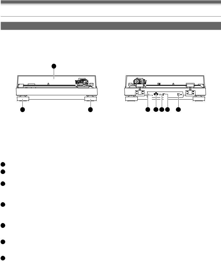
Part names and functions
Front and rear view diagram
1
2 |
2 |
1Dust cover
2Feet
Adjust the level of the product.
3Pre-amplifier selector switch
If using an amplifier with a PHONO input jack, set this switch to the PHONO position. If connecting to the AUX jack of an amplifier, set this switch to the LINE position.
4Stereo output terminals
Connect the RCA audio cable. Connect it to either the amplifier's PHONO input jack or its line input jack. The red terminal is the right channel and the white terminal is the left channel.
5Ground (earth) terminal
Connect the amplifier's ground (earth) terminal to this terminal using the RCA audio cable's ground line.
6USB output
Use this output to connect your turntable to the USB input of your computer.
7Power input jack
Connect the AC adapter.
3 |
4 |
5 |
6 |
7 |
4
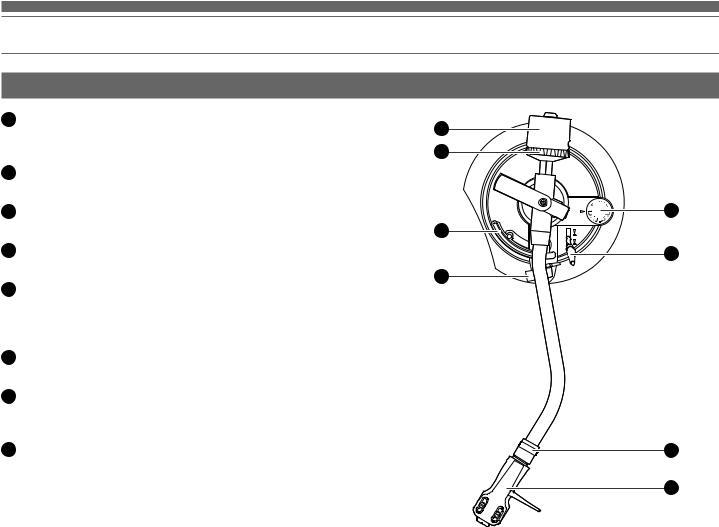
Part names and functions
Tonearm
1Counterweight
Balances the tonearm and adjusts to provide the proper tracking force.
2Tracking force gauge ring
Use to adjust the tracking force.
3Tonearm lift
Moves the tonearm vertically to and from the face of the record.
4Tonearm rest with clamp
Use the clamp to secure the tonearm so that it does not move.
5Anti-skate control dial
While the record is playing, a force acts on the stylus tip to pull it inward. This force can be counteracted by setting the same values for anti-skate and the tracking force.
6Tonearm lift control lever
Operates the tonearm lift.
7Locking ring
Rotate the ring to the left (counterclockwise) to secure the headshell. To remove the headshell, rotate the ring to the right.
8Headshell
The cartridge (AT-VM95E) is attached to the headshell (AT-HS6).
1
2
5
3
6
4
7
8
5
 Loading...