

Page 1
REVISED 8/8/00
1
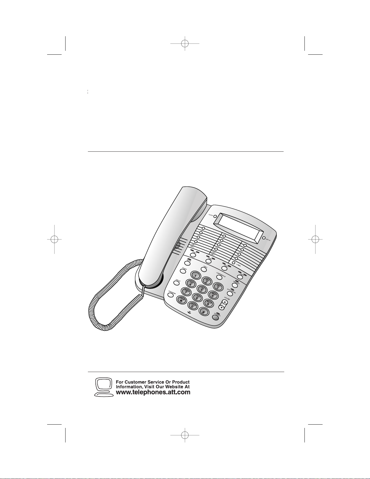
Four-Line Speakerphone 924
1
Please also read
Part 1 — Important
Product Information
USER’S MANUAL
Par t 2
AT&T and the globe symbol are registered trademarks of AT&T Corp.licensed to Advanced American Telephones.
924 book_1ATT 8/8/00 11:24 AM Page ii
Page 2

© 2000 Advanced American Telephones. All rights reserved.
Printed in Mexico. 850003997 Issue 1AT&T 8/00
924 book_1ATT 8/8/00 11:24 AM Page iii
Page 3

INSTALLATION . . . . . . . . . . . . . . . . . . . . . . 3
Table/Desk Installation ................. 3
Wall Installation ............................ 7
Headset Installation....................... 9
Dial Mode.................................... 10
Setting Time and Date................. 10
TELEPHONE OPERATION . . . . . 11
Automatic Line Selection............ 12
Making Calls ................................ 12
Answering Calls.......................... 13
Changing During a Call............... 13
Call Volume................................. 13
Mute............................................ 13
Redial .......................................... 14
Automatic Redial......................... 14
Hold ............................................ 14
Switching Lines During a Call..... 15
Conference Calls ......................... 15
Conference Call Options............ 15
Flash............................................ 16
Temporary Tone Dialing.............. 16
Timer........................................... 16
Ringer Volume ............................. 16
TELEPHONE MEMORY . . . . . . . . . . 17
Storing Memory Number s .......... 17
Storing a Pause in a
Memory Number..................... 17
Directory Card............................ 17
Dialing Memory Numbers .......... 17
Viewing Memory Numbers......... 17
Dialing Long Numbers................ 18
Erasing Memory Numbers .......... 18
IN CASE OF DIFFICULTY . . . . . 19
CONTENTS
1
924 book_1ATT 8/8/00 11:24 AM Page 1
Page 4

924 book_1ATT 8/8/00 11:24 AM Page 2
Page 5
INSTALLA TION
3
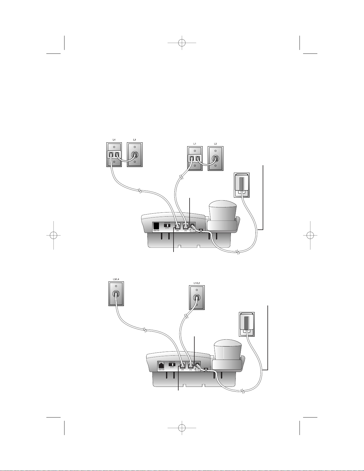
Two Two-Line Jacks
Table/Desk Installation
1 Connect the line cord(s) to telephone.
Four One-Line Jacks (To use this installation option,you’ll need
two two-line adapters. Adapters are available for purchase at retail
stores or by calling 1 800 222-3111.)
Power cord
Power cord
L1/L2 jack
L3/L4 jack
L1/L2 jack
L3/L4 jack
924 book_1ATT 8/8/00 11:24 AM Page 3
Page 6
INSTALLA TION
4
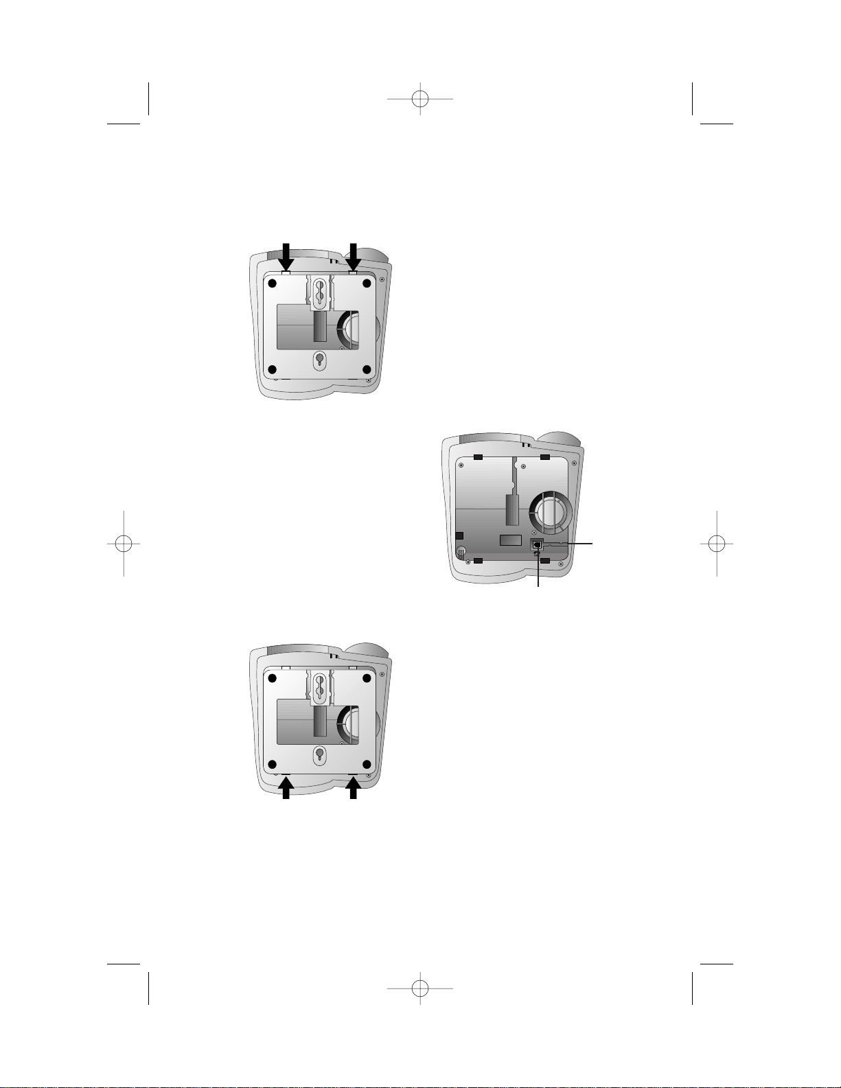
2 Remove the base.
3 Connect the handset cord.
Plug one end of the coiled
handset cord into the jack on
the underside of the phone.
Pass the cord through the
channel from the jack to the
side of the base. Plug the
other end into the handset,
and hang up.
4 Replace the base with the widest part at the top.
Channel
Jack
924 book_1ATT 8/8/00 11:24 AM Page 4
Page 7
INSTALLA TION
5
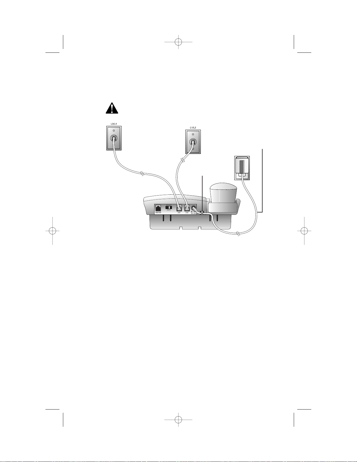
5 Connect the power adapter.
Use only the power adapter provided with this product. To
obtain a replacement,call 1 800 222-3111.
Fit the power cord behind the strain relief tab. Then plug the
smaller end into the power jack on the back of the system.
Plug the power cord into an electrical outlet that is not controlled
by a wall switch.
NOTE: The power adapter connects the same way whether you
use four one-line jacks or two two-line jacks.
6 Check for dial tone.
Press L,lift the handset, and listen for dial tone. Repeat for
Lines 2,3, and 4. If you cannot hear a dial tone,see IN CASE OF
DIFFICULTY.
7 Confirm Lines 1, 2, 3, and 4.
Make sure none of the lines is in use. Press L and call one of
your telephone numbers. If you hear a busy signal, L is the
number you called. If another line rings, it is the number you
called. Repeat Step 7 to check all other connected lines.
Strain-relief tab
Power cord
924 book_1ATT 8/8/00 11:24 AM Page 5
Page 8

INSTALLA TION
6
NOTE: If you want to connect another device (such as a modem or fax
machine) to the wall jack, you can use the jack on the phone labeled
DATAPORT. This convenience port uses Line X; a call picked up on Line
X at this or another extension may interrupt a fax, modem, or message
transmission.
Data port
924 book_1ATT 8/8/00 11:24 AM Page 6
Page 9

INSTALLA TION
7
Wall Installation
1 Reverse the handset tab.
2 Remove the base.
3 Connect the bundled line
cords to the telephone.
Leave the telephone line cords
bundled. See Step 1 in
“Table/Desk Installation”for
line cord connections.
Switchhook
Handset tab
4 Connect the handset cord.
Plug one end of the coiled handset cord into the jack on the
bottom of the phone. Pass the cord through the channel from the
jack to the side of the phone. Plug the other end into the handset,
and hang up.
a) Hold down
switchhook;
slide tab up
and out.
b) Turn tab so
the end with
the “hook”
is up.
c) Inser t the
tab back
into its slot.
Remove
Channel
Jack
924 book_1ATT 8/8/00 11:24 AM Page 7
Page 10

5 Turn the base and attach it to the bottom of the phone.
6 Connect the power adapter.
Use only the power adapter provided with this product. To
obtain a replacement,call 1 800 222-3111.
Fit the power cord behind the strain relief tab. Then plug the
smaller end into the power jack on the back of the system.
Plug the power cord into an electrical outlet that is not controlled
by a wall switch.
7 Mount the phone on the wall
8 Follow Steps 6 and 7 under Table/Desk Installation.
INSTALLATION
8
a) Turn b) Attach
924 book_1ATT 8/8/00 11:24 AM Page 8
Page 11

INSTALLA TION
9
Headset Installation
You can use this phone hands-free when you install a 2.5 mm headset
(purchased separately).
Headset jack
924 book_1ATT 8/8/00 11:24 AM Page 9
Page 12

INSTALLA TION
10
Dial Mode
This telephone will work with touch tone or dial pulse (rotary) service.
Each line comes set in the tone (tt) mode. Make sure you choose the
correct dialing method (DP or tt) for each telephone line;touch tone
dialing will not work if you have dial pulse service.
1 Press U.
2 Select the line.
3 Press #.
4 Press 3 to change the dial mode to DP (dial pulse)
— OR —
Press 8 to change the dial mode to tt (tone).
5 Press U to exit
— OR —
Press a LINE button to set the dial mode for that line.
Even when set to dial pulse (DP),the phone can be switched temporarily
to tone for access to services that require tone signaling,including some
tone-activated computer systems. To switch from pulse to tone dialing
during a phone call,see “Temporary Tone Dialing”in TELEPHONE
OPERATION.
Setting Time and Date
The screen displays the time and date when the phone is not in use and
the ringers are on.
1 Press C.
2 Use the dial pad to enter the correct time. For example,press
1 5 3 to set the time to 1:53.
3 Press * for AM or # for PM.
4 Enter the correct date. For example,press 9 0 1 to set the date
to September 1.
5 Press C again.
To Reset Time Only
Follow Steps 1–3 a bove,then press C.
To Reset Date Only
Follow Steps 1, 3, 4, and 5 above (skip Step 2).
924 book_1ATT 8/8/00 11:24 AM Page 10
Page 13

HEADLINE RIGHT
HEADLINE R-SUB
11
TELEPHONE OPERATION
Red Line-in-Use lights
On steadily:
Line in use
Flashing slowly:
Line on hold
Flashing quickly:
Line ringing
Display screen
Line Selection lights
Green light indicates
selected line
Indicates headset
in use
Indicates
speakerphone in use
Indicates mute
is active
Indicates AutoRedial
is active
924 book_1ATT 8/8/00 11:24 AM Page 11
Page 14

Automatic Line Selection
When you lift the handset,press K,or press h,the phone will
connect to the prime telephone line. The phone is preset so that Line 1 is
the Prime Line.
To change which line the system automatically selects (Prime Line):
1 Press U.
2 Select the line you want to act as the Prime Line. The screen
displays the status of this line.
3 Press 7 to choose this line as the new Prime Line. The screen
displays the new Prime Line.
4 Press U to exit
— OR —
Press another LINE button to set up that line.
This phone also allows line pre-selection for making and answering calls. If
you want to use a specific line,press that LINE button and then make or
answer your call.
The green Line Selection light indicates which line will be used when
making or answering a call.
Making Calls
You can make calls using the handset,speakerphone, or headset.
1 Lift the handset
— OR —
Press K
— OR —
Press h.
The Prime Line will be selected automatically.
2 Dial the call.
To make a call on a line other than the Prime Line, press the desired
LINE button,then follow Steps 1 and 2 above.
NOTE: The red SPEAKERPHONE light goes on when the speakerphone is
in use. The red HEADSET light goes on when the headset is in use.
TELEPHONE OPERATION
12
924 book_1ATT 8/8/00 11:24 AM Page 12
Page 15

Answering Calls
Each line has a different ringer tone to signal an incoming call. A red
Line-in-Use light will also flash to identify the r inging line.
You can answer and end calls using the handset,speakerphone,or headset.
Answer a Call End a Call
Press LINE button for ringing
line,then:
Handset Lift handset. Replace handset.
Speakerphone Press K. Press K.
Headset Press h. Press h.
NOTE: When you are using a line and a call is received on another line, the
red Line-in-Use light for the ringing line will flash and the set will sound a
quiet, short ring for the ringing line.
Changing During a Call
• To switch from handset to speakerphone while on a call,press K
and replace the handset. To switch from speakerphone to handset,lift
the handset.
• To switch from handset to headset,press h and replace the
handset. To switch from headset to handset,lift the handset.
• To switch from speakerphone to headset,press h. To switch
from headset to speakerphone,press K.
Call Volume
You can adjust the handset,speaker,or headset volume during your call.
Press VOLUME + to increase volume or VOLUME - to lower volume.
Volume adjustments for one calling method (handset,headset, or
speakerphone) do not affect volume for other methods.
Mute
Press M to prevent the other party from hearing you (you will still be
able to hear the other party). The MUTE light goes on. Press M again to
continue your conversation.
NOTE: T his feature works with the handset, speakerphone, and headset.
Mute is cancelled if you switch from the handset to speakerphone or
headset, or vice versa.
TELEPHONE OPERATION
13
924 book_1ATT 8/8/00 11:24 AM Page 13
Page 16

Redial
1 Lift the handset,press K, or press h and listen for a
dial tone. The Pr ime Line will be selected automatically.
2 Press A to call the last number dialed (up to 24 digits).
To override Prime Line selection, press the desired LINE button,then
follow Steps 1 and 2 a bove.
Automatic Redial
This phone can automatically redial the last number you called up to
10 times.
NOTE: To use this feature with a line other than the Prime Line, press a
LINE button before Steps 1 and 2 below.
1 Press A without lifting the handset,pressing K,or
pressing h. You will hear the number being dialed. If the
called number is busy,the phone redials ever y 60 seconds (up to
10 times).
2 When the call is answered,lift the handset,press K, or press
h to talk.
To stop automatic redialing at any time,press A again. Lifting the
handset,pressing K or pressing h to make a call will also
cancel automatic redial.
NOTE: T his feature cannot be used to add a third party to an existing
call (conferencing). This feature only works when the phone is not
in use.
Hold
When a call is put on hold,nothing either par ty says can be heard,and the
red Line-in-Use light for the held line flashes. You cannot access any special
features.
1 Press H. If you are using the handset,you can place the phone
in the cradle.
2 To return to the conversation,press the appropriate LINE button,
then lift the handset,press K or press h (if you do not
select a line,you will be connected to the Prime Line)
— OR —
Lift the handset of an extension phone of the line on hold.
TELEPHONE OPERATION
14
924 book_1ATT 8/8/00 11:24 AM Page 14
Page 17

TELEPHONE OPERATION
15
Switching Lines During a Call
During a call on one line,you can make or answer a call on another line by
pressing H. You can use the H and LINE buttons to switch back and
forth between calls as often as necessary. Example: While using Line 1,
Line 2 rings:
1 Press H to hold Line 1.
2 Press l,then lift the handset,press K or press h
to answer the other call.
3 Press L,then lift the handset,press K or press h
to hang up Line 2 and return to your first call
— OR —
Press H to hold Line 2,press L,then lift the handset,press
K or press h to return to your first call.
Conference Calls
You can use two lines at the same time to set up a three-way conference call.
1 Make or answer a call,and press H.
2 Establish a call on another line.
3 Press c.
4 Hang up to end a conference call.
If one caller hangs up during a conference call,you might hear a dial tone.
Press the LINE button of the remaining call to disconnect the other line
and eliminate the dial tone.
Conference Call Options
To place a conference call on hold:
1 Press H to put both lines on hold.
2 Press c to release hold and continue the conference call.
NOTE: If more than one line is on hold, you cannot form a conference
while talking to a third party.
To talk privately with one caller:
1 Press H.
2 Press the LINE button of the person with whom you want to
speak privately.
3 Press c to return to your conference call.
To disconnect one party from a conference call and keep the other one on
the line,press the LINE button of the call you want to continue.
924 book_1ATT 8/8/00 11:24 AM Page 15
Page 18

Flash
The Flash feature is useful if you have subscribed to custom calling services
from your local telephone company. Press F instead of pressing the
switchhook to activate services such as Call Waiting or Three-Way Calling.
You may have to press other buttons before or after F as explained in
the custom calling instructions provided by your local telephone company.
The F button is used only as a substitute for pressing the switchhook.
Temporary Tone Dialing
If you have dial pulse (rotary) service,you can change from dial pulse to
touch tone dialing during a call by pressing *. This is useful if you need to
send touch tone signals for access to telephone banking or long-distance
services.
1 Dial the number.
2 Press *. Buttons pressed after this send touch tone signals.
3 After you hang up,the phone automatically returns to dial pulse
(rotary) service.
Timer
The timer starts automatically when you make or answer a call and will
appear on the screen approximately 40 seconds into the call.
The screen displays elapsed time in minutes and seconds. (After one hour
the timer resets to 00:00 and begins again.)
The timer stops automatically when you hang up. The screen displays the
recorded time for about 10 seconds.
Ringer Volume
You must set the ringer volume independently for each line.
1 Press U.
2 Press the LINE button for the line whose volume you want to set.
3 Press VOLUME + to increase volume for the selected line
— OR —
Press VOLUME - to lower volume. Setting to the lowest volume
level (0) turns off the ringer for that line.
NOTE: Follow Steps 2 and 3 to adjust ringer(s) when the phone is not
in use.
TELEPHONE OPERATION
16
924 book_1ATT 8/8/00 11:24 AM Page 16
Page 19

Storing Memory Numbers
1 Press G.
2 Dial the telephone number (up to 24 digits). To enter a space
between digits,press S once.
— OR —
Press A to store the last number dialed.
3 Press a memory button
— OR —
Press ,then press a memor y button.
4 Repeat Steps 2 and 3 to store another number.
5 Press G to exit programming mode.
NOTE: If you do not press G, the number will be stored and the
phone will exit programming automatically after about two seconds.
Storing a Pause in a Memory Number
You can program a three-second pause in the dialing sequence of a
memory number. While storing a memor y number,press ,S
where you want the pause to occur.
NOTE: Every memory location can store 24 digits. Each three–second
pause counts as one digit.
Directory Card
Remove the plastic cover and the directory card. Wr ite your telephone
numbers in the spaces provided,and wr ite the telephone numbers (or
names) stored in each memory location. Reinstall the card and plastic
cover.
Dialing Memory Numbers
1 Lift the handset,press K or press h. The Prime Line is
automatically selected. Listen for a dial tone.
2 Press a memory button
— OR —
Press -,then press a memor y button.
Viewing Memory Numbers
To view a number when the telephone is not in use,press the memory
button where the number is stored. The number displayed on the screen
will not be dialed.
LOWER
LOWER
HEADLINE RIGHT
HEADLINE R-SUB
17
TELEPHONE MEMORY
924 book_1ATT 8/8/00 11:24 AM Page 17
Page 20

Dialing Long Numbers
Use Two Memory Locations
You can store a dialing sequence of more than 24 digits by dividing it and
storing it in two memory locations (see “Storing Memory Number s”). To
dial:
1 Get a dial tone.
2 Press the memory button for the first location,and wait for dialing
to stop.
3 Press the memory button for the second location.
Combine Manual and Memory Dialing
You can store part of a long number in a memory location. To dial,use the
memory button for the stored portion and manually dial the other digits. If
the stored portion is dialed first,wait for dialing to stop before you
continue with manual dialing.
Erasing Memory Numbers
To remove a number from memory,store another number in its place. To
clear a memory location and leave it empty:
1 Press G.
2 Press the location of the memory location you want to clear.
3 Press G.
TELEPHONE MEMORY
18
924 book_1ATT 8/8/00 11:24 AM Page 18
Page 21

If you have difficulty operating this phone,try the suggestions below. For
Customer Service,visit our website at www.telephones.att.com or call
1 800 222–3111. Please r etain your r eceipt as your proof of pur chase.
No Dial Tone
• Make sure all plugs are connected properly. Inspect the line cord
connections at the modular jack and at the telephone. Also inspect the
coiled handset cord connections at both ends.
• Unplug the telephone and connect it to another modular jack. If it still
does not work,and other telephones in your home are working,the
problem is with this telephone.
Call Cannot Be Dialed or Is Dialed Slowly
• Make sure you chose the correct Dial Mode (see INSTALLATION). If
you have dial pulse service,you cannot dial numbers with the phone
set to touch tone dialing.
• If you have just used the Temporary Tone feature,leave the handset on
the base for a few seconds before making another call.
Automatic Redial Interrupted
Lifting the handset,pressing K or h, or pressing a LINE button
to make a call will cancel Automatic Redial.
Difficulty Storing Numbers in Memory
• Make sure you are pressing the correct sequence of buttons for storing
numbers.
• If you are interr upted by a recorded announcement telling you to hang
up or by a loud buzzing noise,hang up and enter the number while
the phone is not in use.
• Try calling the number you want to store in memory. When the call is
ended,press G, A,and a memory button.
Problems with Line-in-Use Lights or
Line Selection Indicators
Make sure all plugs are connected properly. Inspect the line cord
connections at the modular jack and at the telephone. Also inspect the
coiled handset cord connections at both ends.
HEADLINE RIGHT
HEADLINE R-SUB
19
IN CASE OF DIFFICULTY
924 book_1ATT 8/8/00 11:24 AM Page 19
Page 22

Telephone Does Not Ring
• Make sure the ringer volume for this line is not set to 0.
• If there are several other telephones on the same line,try
disconnecting some of the other telephones. Having too many
telephones connected can also create problems such as low ringer
volume or impaired sound quality during calls.
IN CASE OF DIFFICULTY
20
924 book_1ATT 8/8/00 11:24 AM Page 20
 Loading...