


 Loading...
Dual Rail LCD KVM Switch
KL9108 / KL9116
User Manual
www.aten.com

KL9108 / KL9116 User Manual
FCC, CE Information
FEDERAL COMMUNICATIONS COMMISSION INTERFERENCE STATEMENT: This equipment has been tested and found to comply with the limits for a Class A digital device, pursuant to Part 15 of the FCC Rules. These limits are designed to provide reasonable protection against harmful interference when the equipment is operated in a commercial environment. This equipment generates, uses, and can radiate radio frequency energy and, if not installed and used in accordance with the instruction manual, may cause harmful interference to radio communications. Operation of this equipment in a residential area is likely to cause harmful interference in which case the user will be required to correct the interference at his own expense.
FCC Caution: Any changes or modifications not expressly approved by the party responsible for compliance could void the user's authority to operate this equipment.
CE Warning: This is a class A product. In a domestic environment this product may cause radio interference in which case the user may be required to take adequate measures.
RoHS
This product is RoHS compliant.
SJ/T 11364-2006
The following contains information that relates to China.
ii

KL9108 / KL9116 User Manual
User Information
Online Registration
Be sure to register your product at our online support center:
International http://eservice.aten.com
Telephone Support
For telephone support, call this number:
International |
886-2-8692-6959 |
|
|
China |
86-10-5255-0110 |
|
|
Japan |
81-3-5615-5811 |
|
|
Korea |
82-2-467-6789 |
|
|
North America |
1-888-999-ATEN ext 4988 |
|
|
United Kingdom |
44-8-4481-58923 |
|
|
User Notice
All information, documentation, and specifications contained in this manual are subject to change without prior notification by the manufacturer. The manufacturer makes no representations or warranties, either expressed or implied, with respect to the contents hereof and specifically disclaims any warranties as to merchantability or fitness for any particular purpose. Any of the manufacturer's software described in this manual is sold or licensed as is. Should the programs prove defective following their purchase, the buyer (and not the manufacturer, its distributor, or its dealer), assumes the entire cost of all necessary servicing, repair and any incidental or consequential damages resulting from any defect in the software.
The manufacturer of this system is not responsible for any radio and/or TV interference caused by unauthorized modifications to this device. It is the responsibility of the user to correct such interference.
The manufacturer is not responsible for any damage incurred in the operation of this system if the correct operational voltage setting was not selected prior to operation. PLEASE VERIFY THAT THE VOLTAGE SETTING IS CORRECT BEFORE USE.
iii

KL9108 / KL9116 User Manual
Package Contents
Basic Package
The basic KL9108 / KL9116 package consists of:
1KL9108 or KL9116 Dual Rail LCD KVM Switch with Standard Rack Mount Kit
2Custom KVM Cable Sets
1 Power Cord
1 User Instructions*
1 Quick Start Guide
Optional Equipment
Depending on any optional equipment that you may have purchased, one of the following may be included in your package:
Standard Rack Mounting Kit - Long
Easy-Installation Rack Mounting Kit - Short
Easy-Installation Rack Mounting Kit - Long
Check to make sure that all of the components are present and in good order. If anything is missing, or was damaged in shipping, contact your dealer.
Read this manual thoroughly and follow the installation and operation procedures carefully to prevent any damage to the switch or to any other devices on the KL9108 / KL9116 installation.
*Changes may have been made to the manual since it was published. Please visit our Website to check for the most up-to-date version.
Copyright © 2014 ATEN® International Co., Ltd.
Manual Part No. PAPE-0267-3AXG
Manual Date: 2014-10-01
Altusen and the Altusen logo are registered trademarks of ATEN International Co., Ltd. All rights reserved. All other brand names and trademarks are the registered property of their respective owners.
iv

KL9108 / KL9116 User Manual
Contents
FCC, CE Information. . . . . . . . . . . . . . . . . . . . . . . . . . . . . . . . . . . . . . . . . . ii SJ/T 11364-2006. . . . . . . . . . . . . . . . . . . . . . . . . . . . . . . . . . . . . . . . . . . . . ii User Information . . . . . . . . . . . . . . . . . . . . . . . . . . . . . . . . . . . . . . . . . . . . .iii Online Registration . . . . . . . . . . . . . . . . . . . . . . . . . . . . . . . . . . . . . . . .iii Telephone Support . . . . . . . . . . . . . . . . . . . . . . . . . . . . . . . . . . . . . . . .iii User Notice . . . . . . . . . . . . . . . . . . . . . . . . . . . . . . . . . . . . . . . . . . . . . .iii Package Contents. . . . . . . . . . . . . . . . . . . . . . . . . . . . . . . . . . . . . . . . . . . iv Basic Package. . . . . . . . . . . . . . . . . . . . . . . . . . . . . . . . . . . . . . . . . . . iv Optional Equipment. . . . . . . . . . . . . . . . . . . . . . . . . . . . . . . . . . . . . . . iv About This Manual . . . . . . . . . . . . . . . . . . . . . . . . . . . . . . . . . . . . . . . . . . . x Overview . . . . . . . . . . . . . . . . . . . . . . . . . . . . . . . . . . . . . . . . . . . . . . . . x Conventions . . . . . . . . . . . . . . . . . . . . . . . . . . . . . . . . . . . . . . . . . . . . xi Product Information. . . . . . . . . . . . . . . . . . . . . . . . . . . . . . . . . . . . . . . . . . xi
Chapter 1.
Introduction
Overview . . . . . . . . . . . . . . . . . . . . . . . . . . . . . . . . . . . . . . . . . . . . . . . . . . . 1
Features . . . . . . . . . . . . . . . . . . . . . . . . . . . . . . . . . . . . . . . . . . . . . . . . . . . 3
Requirements . . . . . . . . . . . . . . . . . . . . . . . . . . . . . . . . . . . . . . . . . . . . . . . 5
External Console . . . . . . . . . . . . . . . . . . . . . . . . . . . . . . . . . . . . . . . . . . 5
Computers. . . . . . . . . . . . . . . . . . . . . . . . . . . . . . . . . . . . . . . . . . . . . . . 5
Remote Computers . . . . . . . . . . . . . . . . . . . . . . . . . . . . . . . . . . . . . . . . 5
Cables . . . . . . . . . . . . . . . . . . . . . . . . . . . . . . . . . . . . . . . . . . . . . . . . . . 6
Converters and Adapters . . . . . . . . . . . . . . . . . . . . . . . . . . . . . . . . . . . 6
Operating Systems . . . . . . . . . . . . . . . . . . . . . . . . . . . . . . . . . . . . . . . . 7
Components . . . . . . . . . . . . . . . . . . . . . . . . . . . . . . . . . . . . . . . . . . . . . . . . 8
Front View . . . . . . . . . . . . . . . . . . . . . . . . . . . . . . . . . . . . . . . . . . . . . . . 8
Keyboard Module . . . . . . . . . . . . . . . . . . . . . . . . . . . . . . . . . . . . . . . . . 9
LCD Module . . . . . . . . . . . . . . . . . . . . . . . . . . . . . . . . . . . . . . . . . . . . 10
Rear View . . . . . . . . . . . . . . . . . . . . . . . . . . . . . . . . . . . . . . . . . . . . . . 11
Chapter 2.
Hardware Setup
Before You Begin . . . . . . . . . . . . . . . . . . . . . . . . . . . . . . . . . . . . . . . . . . . 13
Standard Rack Mounting. . . . . . . . . . . . . . . . . . . . . . . . . . . . . . . . . . . . . . 14
Single Stage Installation . . . . . . . . . . . . . . . . . . . . . . . . . . . . . . . . . . . . . . 16
Two Stage Installation. . . . . . . . . . . . . . . . . . . . . . . . . . . . . . . . . . . . . . . . 18
Chapter 3.
Basic Operation
Opening the Console . . . . . . . . . . . . . . . . . . . . . . . . . . . . . . . . . . . . . . . . 21
Opening Separately. . . . . . . . . . . . . . . . . . . . . . . . . . . . . . . . . . . . . . . 21
Opening Together . . . . . . . . . . . . . . . . . . . . . . . . . . . . . . . . . . . . . . . . 23
v

KL9108 / KL9116 User Manual
Operating Precautions . . . . . . . . . . . . . . . . . . . . . . . . . . . . . . . . . . . . 24
Closing the Console . . . . . . . . . . . . . . . . . . . . . . . . . . . . . . . . . . . . . . . . . 25
LCD OSD Configuration . . . . . . . . . . . . . . . . . . . . . . . . . . . . . . . . . . . . . . 27
The LCD Buttons. . . . . . . . . . . . . . . . . . . . . . . . . . . . . . . . . . . . . . . . . 27
The Adjustment Settings . . . . . . . . . . . . . . . . . . . . . . . . . . . . . . . . . . . 28
Port Selection . . . . . . . . . . . . . . . . . . . . . . . . . . . . . . . . . . . . . . . . . . . . . . 29
Manual Port Switching . . . . . . . . . . . . . . . . . . . . . . . . . . . . . . . . . . . . 29
Hot Plugging . . . . . . . . . . . . . . . . . . . . . . . . . . . . . . . . . . . . . . . . . . . . . . . 29
Powering Off and Restarting. . . . . . . . . . . . . . . . . . . . . . . . . . . . . . . . . . . 29
Port ID Numbering . . . . . . . . . . . . . . . . . . . . . . . . . . . . . . . . . . . . . . . . . . 29
Chapter 4.
Administration
Overview. . . . . . . . . . . . . . . . . . . . . . . . . . . . . . . . . . . . . . . . . . . . . . . . . . 31
The Local Console . . . . . . . . . . . . . . . . . . . . . . . . . . . . . . . . . . . . . . . . . . 31
The Main Page . . . . . . . . . . . . . . . . . . . . . . . . . . . . . . . . . . . . . . . . . . . . . 33
Quick View Ports. . . . . . . . . . . . . . . . . . . . . . . . . . . . . . . . . . . . . . . . . 33
The List Function. . . . . . . . . . . . . . . . . . . . . . . . . . . . . . . . . . . . . . . . . 34
Port Names . . . . . . . . . . . . . . . . . . . . . . . . . . . . . . . . . . . . . . . . . . . . . 36
Port Operation . . . . . . . . . . . . . . . . . . . . . . . . . . . . . . . . . . . . . . . . . . . . . 38
The Configuration Page . . . . . . . . . . . . . . . . . . . . . . . . . . . . . . . . . . . . . . 39
The Administration Page . . . . . . . . . . . . . . . . . . . . . . . . . . . . . . . . . . . . . 41
General . . . . . . . . . . . . . . . . . . . . . . . . . . . . . . . . . . . . . . . . . . . . . . . . 41
User Management. . . . . . . . . . . . . . . . . . . . . . . . . . . . . . . . . . . . . . . . 42
Service Configuration . . . . . . . . . . . . . . . . . . . . . . . . . . . . . . . . . . . . . 45
Network . . . . . . . . . . . . . . . . . . . . . . . . . . . . . . . . . . . . . . . . . . . . . . . 47
ANMS . . . . . . . . . . . . . . . . . . . . . . . . . . . . . . . . . . . . . . . . . . . . . . . . . 48
Security . . . . . . . . . . . . . . . . . . . . . . . . . . . . . . . . . . . . . . . . . . . . . . . . 53
Customization . . . . . . . . . . . . . . . . . . . . . . . . . . . . . . . . . . . . . . . . . . 55
Date/Time . . . . . . . . . . . . . . . . . . . . . . . . . . . . . . . . . . . . . . . . . . . . . . 59
The Log Page . . . . . . . . . . . . . . . . . . . . . . . . . . . . . . . . . . . . . . . . . . . . . . 60
Upgrading the Firmware . . . . . . . . . . . . . . . . . . . . . . . . . . . . . . . . . . . . . . 61
Chapter 5.
Browser Operation
Overview. . . . . . . . . . . . . . . . . . . . . . . . . . . . . . . . . . . . . . . . . . . . . . . . . . 63
Logging In . . . . . . . . . . . . . . . . . . . . . . . . . . . . . . . . . . . . . . . . . . . . . . . . . 63
Webpage Layout. . . . . . . . . . . . . . . . . . . . . . . . . . . . . . . . . . . . . . . . . . . . 65
Webpage Icons . . . . . . . . . . . . . . . . . . . . . . . . . . . . . . . . . . . . . . . . . . 65
The General Dialog Box . . . . . . . . . . . . . . . . . . . . . . . . . . . . . . . . . . . 66
Webpage Buttons . . . . . . . . . . . . . . . . . . . . . . . . . . . . . . . . . . . . . . . . 67
Chapter 6.
Windows Client Port Operation
Activating the OSD . . . . . . . . . . . . . . . . . . . . . . . . . . . . . . . . . . . . . . . . . . 69
Before you Begin. . . . . . . . . . . . . . . . . . . . . . . . . . . . . . . . . . . . . . . . . 71
vi

KL9108 / KL9116 User Manual
Graphics Configuration Dialog Box . . . . . . . . . . . . . . . . . . . . . . . . . . . 72
The Windows Client OSD . . . . . . . . . . . . . . . . . . . . . . . . . . . . . . . . . . . . . 74
Windows Client Control Panel. . . . . . . . . . . . . . . . . . . . . . . . . . . . . . . . . . 75
Hotkey Setup. . . . . . . . . . . . . . . . . . . . . . . . . . . . . . . . . . . . . . . . . . . . 76
Video Adjustment . . . . . . . . . . . . . . . . . . . . . . . . . . . . . . . . . . . . . . . . 78
The Message Board . . . . . . . . . . . . . . . . . . . . . . . . . . . . . . . . . . . . . . 81
The Main Page . . . . . . . . . . . . . . . . . . . . . . . . . . . . . . . . . . . . . . . . . . . . . 84
Port Operation. . . . . . . . . . . . . . . . . . . . . . . . . . . . . . . . . . . . . . . . . . . . . . 85
The OSD Toolbar . . . . . . . . . . . . . . . . . . . . . . . . . . . . . . . . . . . . . . . . 85
Recalling the OSD. . . . . . . . . . . . . . . . . . . . . . . . . . . . . . . . . . . . . . . . 85
OSD Hotkey Summary Table . . . . . . . . . . . . . . . . . . . . . . . . . . . . . . . 86
OSD Toolbar Icons . . . . . . . . . . . . . . . . . . . . . . . . . . . . . . . . . . . . . . . 86
Panel Array Mode . . . . . . . . . . . . . . . . . . . . . . . . . . . . . . . . . . . . . . . . 87
Multiuser Operation. . . . . . . . . . . . . . . . . . . . . . . . . . . . . . . . . . . . . . . . . . 89
Keyboard Hotkey Operation . . . . . . . . . . . . . . . . . . . . . . . . . . . . . . . . . . . 90
Auto Scanning . . . . . . . . . . . . . . . . . . . . . . . . . . . . . . . . . . . . . . . . . . . 90
Setting the Scan Interval . . . . . . . . . . . . . . . . . . . . . . . . . . . . . . . . . . . 90
Invoking Auto Scan . . . . . . . . . . . . . . . . . . . . . . . . . . . . . . . . . . . . . . . 90
Pausing Auto Scan . . . . . . . . . . . . . . . . . . . . . . . . . . . . . . . . . . . . . . . 91
Exiting Auto Scan . . . . . . . . . . . . . . . . . . . . . . . . . . . . . . . . . . . . . . . . 91
Skip Mode . . . . . . . . . . . . . . . . . . . . . . . . . . . . . . . . . . . . . . . . . . . . . . 91
Keyboard and Mouse Considerations . . . . . . . . . . . . . . . . . . . . . . . . . . . . 92
Keystrokes. . . . . . . . . . . . . . . . . . . . . . . . . . . . . . . . . . . . . . . . . . . . . . 92
Mouse Synchronization . . . . . . . . . . . . . . . . . . . . . . . . . . . . . . . . . . . . 93
Chapter 7.
Java Client Port Operation
Activating the OSD . . . . . . . . . . . . . . . . . . . . . . . . . . . . . . . . . . . . . . . . . . 95
The Java Client OSD . . . . . . . . . . . . . . . . . . . . . . . . . . . . . . . . . . . . . . . . 96
The Java Client Control Panel . . . . . . . . . . . . . . . . . . . . . . . . . . . . . . . . . 96
Set Video Parameters . . . . . . . . . . . . . . . . . . . . . . . . . . . . . . . . . . . . . 97
Keypad . . . . . . . . . . . . . . . . . . . . . . . . . . . . . . . . . . . . . . . . . . . . . . . . 97
Mouse Synchronization . . . . . . . . . . . . . . . . . . . . . . . . . . . . . . . . . . . . 98
Message Board . . . . . . . . . . . . . . . . . . . . . . . . . . . . . . . . . . . . . . . . . . 98
Lock Key LEDs and Resolution. . . . . . . . . . . . . . . . . . . . . . . . . . . . . 101
Switch Screen Mode . . . . . . . . . . . . . . . . . . . . . . . . . . . . . . . . . . . . . 101
About . . . . . . . . . . . . . . . . . . . . . . . . . . . . . . . . . . . . . . . . . . . . . . . . . 101
Send Ctrl+Alt+Del . . . . . . . . . . . . . . . . . . . . . . . . . . . . . . . . . . . . . . . 101
Help . . . . . . . . . . . . . . . . . . . . . . . . . . . . . . . . . . . . . . . . . . . . . . . . . . 101
Exit . . . . . . . . . . . . . . . . . . . . . . . . . . . . . . . . . . . . . . . . . . . . . . . . . . 101
Port Operation. . . . . . . . . . . . . . . . . . . . . . . . . . . . . . . . . . . . . . . . . . . . . 102
Panel Array Mode . . . . . . . . . . . . . . . . . . . . . . . . . . . . . . . . . . . . . . . 102
Keyboard Hotkey Operation . . . . . . . . . . . . . . . . . . . . . . . . . . . . . . . . . . 102
vii

KL9108 / KL9116 User Manual
Chapter 8.
The Log File
The Main Screen . . . . . . . . . . . . . . . . . . . . . . . . . . . . . . . . . . . . . . . . . . 103
Chapter 9.
The Log Server
Installation. . . . . . . . . . . . . . . . . . . . . . . . . . . . . . . . . . . . . . . . . . . . . . . . 105
Starting Up . . . . . . . . . . . . . . . . . . . . . . . . . . . . . . . . . . . . . . . . . . . . . . . 106
The Menu Bar . . . . . . . . . . . . . . . . . . . . . . . . . . . . . . . . . . . . . . . . . . . . . 107
Configure. . . . . . . . . . . . . . . . . . . . . . . . . . . . . . . . . . . . . . . . . . . . . . 107
Events . . . . . . . . . . . . . . . . . . . . . . . . . . . . . . . . . . . . . . . . . . . . . . . . 108
Options . . . . . . . . . . . . . . . . . . . . . . . . . . . . . . . . . . . . . . . . . . . . . . . 110
Help. . . . . . . . . . . . . . . . . . . . . . . . . . . . . . . . . . . . . . . . . . . . . . . . . . 110
The Log Server Main Screen . . . . . . . . . . . . . . . . . . . . . . . . . . . . . . . . . 111
Overview . . . . . . . . . . . . . . . . . . . . . . . . . . . . . . . . . . . . . . . . . . . . . . 111
The List Panel . . . . . . . . . . . . . . . . . . . . . . . . . . . . . . . . . . . . . . . . . . 112
The Event Panel . . . . . . . . . . . . . . . . . . . . . . . . . . . . . . . . . . . . . . . . 112
Chapter 10.
AP Operation
Overview. . . . . . . . . . . . . . . . . . . . . . . . . . . . . . . . . . . . . . . . . . . . . . . . . 113
The Windows Client . . . . . . . . . . . . . . . . . . . . . . . . . . . . . . . . . . . . . . . . 113
Installation. . . . . . . . . . . . . . . . . . . . . . . . . . . . . . . . . . . . . . . . . . . . . 113
Starting Up . . . . . . . . . . . . . . . . . . . . . . . . . . . . . . . . . . . . . . . . . . . . 114
The File Menu . . . . . . . . . . . . . . . . . . . . . . . . . . . . . . . . . . . . . . . . . . 116
The Tools Menu . . . . . . . . . . . . . . . . . . . . . . . . . . . . . . . . . . . . . . . . 116
Connecting . . . . . . . . . . . . . . . . . . . . . . . . . . . . . . . . . . . . . . . . . . . . 118
Operation . . . . . . . . . . . . . . . . . . . . . . . . . . . . . . . . . . . . . . . . . . . . . 119
Ending the Session . . . . . . . . . . . . . . . . . . . . . . . . . . . . . . . . . . . . . . 119
The Java Client. . . . . . . . . . . . . . . . . . . . . . . . . . . . . . . . . . . . . . . . . . . . 119
Installation. . . . . . . . . . . . . . . . . . . . . . . . . . . . . . . . . . . . . . . . . . . . . 119
Starting Up . . . . . . . . . . . . . . . . . . . . . . . . . . . . . . . . . . . . . . . . . . . . 120
Operation . . . . . . . . . . . . . . . . . . . . . . . . . . . . . . . . . . . . . . . . . . . . . 121
Chapter 11.
LDAP Server Configuration
Introduction . . . . . . . . . . . . . . . . . . . . . . . . . . . . . . . . . . . . . . . . . . . . . . . 123
Install the Windows 2003 Support Tools . . . . . . . . . . . . . . . . . . . . . . . . 123
Install the Active Directory Schema Snap-in. . . . . . . . . . . . . . . . . . . . . . 124
Create a Start Menu Shortcut Entry . . . . . . . . . . . . . . . . . . . . . . . . . . . . 124
Extend and Update the Active Directory Schema. . . . . . . . . . . . . . . . . . 125
Creating a New Attribute . . . . . . . . . . . . . . . . . . . . . . . . . . . . . . . . . . 125
Extending the Object Class With the New Attribute . . . . . . . . . . . . . 127
Editing Active Directory Users. . . . . . . . . . . . . . . . . . . . . . . . . . . . . . 129
OpenLDAP . . . . . . . . . . . . . . . . . . . . . . . . . . . . . . . . . . . . . . . . . . . . . . . 132
viii

KL9108 / KL9116 User Manual
OpenLDAP Server Installation . . . . . . . . . . . . . . . . . . . . . . . . . . . . . 132
OpenLDAP Server Configuration . . . . . . . . . . . . . . . . . . . . . . . . . . . 133
Starting the OpenLDAP Server . . . . . . . . . . . . . . . . . . . . . . . . . . . . . 134
Customizing the OpenLDAP Schema . . . . . . . . . . . . . . . . . . . . . . . . 135
LDAP DIT Design and LDIF File . . . . . . . . . . . . . . . . . . . . . . . . . . . . 136
Using the New Schema. . . . . . . . . . . . . . . . . . . . . . . . . . . . . . . . . . . 138
Appendix
Safety Instructions. . . . . . . . . . . . . . . . . . . . . . . . . . . . . . . . . . . . . . . . . . 139 General . . . . . . . . . . . . . . . . . . . . . . . . . . . . . . . . . . . . . . . . . . . . . . . 139 Rack Mounting . . . . . . . . . . . . . . . . . . . . . . . . . . . . . . . . . . . . . . . . . 141 Consignes de sécurité. . . . . . . . . . . . . . . . . . . . . . . . . . . . . . . . . . . . . . . 142 Général . . . . . . . . . . . . . . . . . . . . . . . . . . . . . . . . . . . . . . . . . . . . . . . 142 Montage sur bâti . . . . . . . . . . . . . . . . . . . . . . . . . . . . . . . . . . . . . . . . 145 Technical Support . . . . . . . . . . . . . . . . . . . . . . . . . . . . . . . . . . . . . . . . . . 146 International. . . . . . . . . . . . . . . . . . . . . . . . . . . . . . . . . . . . . . . . . . . . 146 North America . . . . . . . . . . . . . . . . . . . . . . . . . . . . . . . . . . . . . . . . . . 146 Specifications . . . . . . . . . . . . . . . . . . . . . . . . . . . . . . . . . . . . . . . . . . . . . 147 OSD Factory Default Settings . . . . . . . . . . . . . . . . . . . . . . . . . . . . . . . . . 148 Trusted Certificates . . . . . . . . . . . . . . . . . . . . . . . . . . . . . . . . . . . . . . . . . 149 Overview . . . . . . . . . . . . . . . . . . . . . . . . . . . . . . . . . . . . . . . . . . . . . . 149 Installing the Certificate . . . . . . . . . . . . . . . . . . . . . . . . . . . . . . . . . . . 150 Certificate Trusted . . . . . . . . . . . . . . . . . . . . . . . . . . . . . . . . . . . . . . . 151 Troubleshooting . . . . . . . . . . . . . . . . . . . . . . . . . . . . . . . . . . . . . . . . . . . 152 Overview . . . . . . . . . . . . . . . . . . . . . . . . . . . . . . . . . . . . . . . . . . . . . . 152 Administration . . . . . . . . . . . . . . . . . . . . . . . . . . . . . . . . . . . . . . . . . . 152 General Operation. . . . . . . . . . . . . . . . . . . . . . . . . . . . . . . . . . . . . . . 153 The Java Client . . . . . . . . . . . . . . . . . . . . . . . . . . . . . . . . . . . . . . . . . 154 The Log Server . . . . . . . . . . . . . . . . . . . . . . . . . . . . . . . . . . . . . . . . . 154 Panel Array Mode . . . . . . . . . . . . . . . . . . . . . . . . . . . . . . . . . . . . . . . 155 The Windows Client . . . . . . . . . . . . . . . . . . . . . . . . . . . . . . . . . . . . . 155 Sun Systems . . . . . . . . . . . . . . . . . . . . . . . . . . . . . . . . . . . . . . . . . . . 156 Screen Resolutions Higher than 1280 x 1024. . . . . . . . . . . . . . . . . . 156 Additional Mouse Synchronization Procedures. . . . . . . . . . . . . . . . . 158 Windows:. . . . . . . . . . . . . . . . . . . . . . . . . . . . . . . . . . . . . . . . . . . . . . 158 Administrator Login Failure . . . . . . . . . . . . . . . . . . . . . . . . . . . . . . . . . . . 160 Optional Rack Mounting . . . . . . . . . . . . . . . . . . . . . . . . . . . . . . . . . . . . . 161 Dedicated Invocation Keys . . . . . . . . . . . . . . . . . . . . . . . . . . . . . . . . . . . 164 About SPHD Connectors . . . . . . . . . . . . . . . . . . . . . . . . . . . . . . . . . . . . 165 Supported KVM Switches . . . . . . . . . . . . . . . . . . . . . . . . . . . . . . . . . . . . 165 Limited Warranty . . . . . . . . . . . . . . . . . . . . . . . . . . . . . . . . . . . . . . . . . . . 166
ix

KL9108 / KL9116 User Manual
About This Manual
This User Manual is provided to help you get the most from your KL9108 / KL9116 system. An overview of the information found in the manual is provided below.
Overview
Chapter 1, Introduction, introduces you to the KL9108 / KL9116 System. Its purpose, features and benefits are presented, and its front and back panel components are described.
Chapter 2, Hardware Setup, provides step-by-step instructions for setting up your installation, and explains some basic operating procedures.
Chapter 3, Basic Operation, explains the fundamental concepts involved in operating the KL9108 / KL9116.
Chapter 4, Administration, explains the administrative procedures that are employed to configure the KL9108 / KL9116’s working environment, as well as how to operate the KL9108 / KL9116 from the local console.
Chapter 5, Browser Operation, describes how to log into the KL9108 / KL9116 with your browser, and explains the functions of the icons and buttons on the KL9108 / KL9116 web page.
Chapter 6, Windows Client Port Operation, explains how to use the Windows Client to access and control the computers connected to the switch.
Chapter 7, Java Client Port Operation, describes how to use the Java Client to access and control the computers connected to the switch.
Chapter 8, The Log File, shows how to use the log file utility to view all the events that take place on the KL9108 / KL9116.
Chapter 9, The Log Server, explains how to install and configure the Log Server.
Chapter 10, AP Operation, describes how to operate the KL9108 / KL9116 using Windows and Java Client application programs, rather than with the browser method.
Chapter 11, LDAP Server Configuration, explains how to configure the KL9108 / KL9116 for LDAP / LDAPS authentication and authorization with Active Directory or OpenLDAP.
An Appendix at the end of the manual provides technical and troubleshooting information.
x
KL9108 / KL9116 User Manual
Conventions
This manual uses the following conventions:
Monospaced |
Indicates text that you should key in. |
[ ] |
Indicates keys you should press. For example, [Enter] means |
|
to press the Enter key. If keys need to be chorded, they |
|
appear together in the same bracket with a plus sign |
|
between them: [Ctrl+Alt]. |
1.Numbered lists represent procedures with sequential steps.
♦Bullet lists provide information, but do not involve sequential steps.
→Indicates selecting the option (on a menu or dialog box, for example), that comes next. For example, Start →Run means to open the Start menu, and then select Run.
Indicates critical information.
Product Information
For information about all ATEN products and how they can help you connect without limits, visit ATEN on the Web or contact an ATEN Authorized Reseller. Visit ATEN on the Web for a list of locations and telephone numbers:
International http://www.aten.com
North America |
http://www.aten-usa.com |
xi

KL9108 / KL9116 User Manual
This Page Intentionally Left Blank
xii
Chapter 1
Introduction
Overview
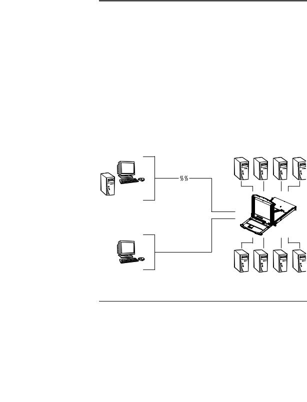
The KL9108 and KL9116 Dual Rail LCD KVM Switches are control units that allow secure access to multiple computers from a single KVM (keyboard, video, and mouse), console. A single KL9108 or KL9116 can control up to 8 or 16 computers, respectively. They consist of an integrated LCD monitor, keyboard, and touchpad in a in a 1U rack-mountable retractable sliding housing.
The LCD and keyboard/touchpad modules slide independently of each other. To maximize space in your data center, the keyboard/touchpad module slides back to "hide away" when not in use, while the thin profile LCD monitor rotates back – flush against the rack – allowing convenient monitoring of computer activity.
The KL9108 / KL9116 features IP-based connectivity that allows one local operator and multiple remote operators to concurrently monitor and access the computers on your installation. Because the it uses TCP/IP for its communications protocol, the KL9108 / KL9116 can be accessed from any computer on the LAN, WAN, or Internet – whether that computer is located down the hall, down the street, or halfway around the world.
Remote
Local
1

KL9108 / KL9116 User Manual
For added convenience, ports for an external keyboard, monitor, and mouse are provided on the rear panel – permitting you to manage the switch from a local console up to 20 meters away. There is also an external PS/2 mouse port on the keyboard module, allowing you to use an external mouse, rather than the touchpad.
Access to any computer connected to the installation from the local console is easily accomplished by means of a powerful mouse driven graphical OSD (On Screen Display) menu system. A convenient Auto Scan feature also permits automatic scanning and monitoring of the activities of all computers running on the installation one by one.
Remote operators connect to the KL9108 / KL9116 via its IP address from anywhere on the LAN, WAN, or Internet via their browsers. Once they successfully log in, they can take control using either the Windows Client or Java Client utility. Inclusion of a Java-based client ensures that the KL9108 / KL9116 is platform independent, and is able to work with most operating systems.
System administrators can handle a multitude of maintenance tasks smoothly and efficiently – from installing and running GUI applications, to BIOS level troubleshooting, routine monitoring, concurrent maintenance, system administration, rebooting and even pre-booting functions – all from a remote connection.
Remote operators can exchange keyboard, video and mouse signals with the computers attached to the KL9108 / KL9116 just as if they were present locally and working on the equipment directly.
Enhanced features include a Panel Array Mode that displays the video output of up to 8 (KL9108) or 16 (KL9116) computers at the same time, and a Message Board that allows logged in users to conveniently and instantly communicate with one other – no matter where in the world they actually are.
The KL9108 / KL9116 utilizes high density 15-pin KVM port connectors instead of the usual 25-pin connectors. This space-saving innovation allows a full 8 / 16 port switch to be conveniently installed in one unit of system rack space.
Setup is fast and easy - plugging cables into their appropriate ports is all that is entailed. Because the KL9108 / KL9116 intercepts keyboard input directly, there is no need to get involved in complex installation routines or to be concerned with incompatibility problems.
2

Chapter 1. Introduction
Since the KL9108 / KL9116's firmware is upgradable over the Internet, you can stay current with the latest functionality improvements simply by downloading firmware updates from our website as they become available.
With its advanced security features, the KL9108 / KL9116 is the fastest, most reliable, most cost effective way to remotely access and manage widely distributed multiple computer installations.
Features
8 (KL9108) / 16 (KL9116) port remote access KVM switch in a sliding dual rail housing with top and bottom clearance for smooth operation in a 1U high rack
Integrated KVM console with 17" LCD monitor, keyboard, and touchpad
Dual slide – LCD Monitor module can slide independently of the keyboard/touchpad module
Dual bus support – one local and one remote user can simultaneously control up to 8 (KL9108) or 16 (KL9116) computers
A single console controls up to 8 (KL9108) or 16 (KL9116) computers – cascade additional units to control up to 128 computers
Remotely access computers via the LAN, WAN, or Internet – control your installation when and where you want
Grayscale option to improve transfer speed in low bandwidth situations
User-selectable network transfer rate
External console ports – manage computers in the LCD KVM switch from an external console (PS/2 keyboard, monitor, and PS/2 mouse)
Supports external PS/2 mouse
Supports dedicated OSD and OSD Toolbar invocation keys
Console lock – enables the console modules to remain securely locked away in position when not in use
Internet browser access – Windows Client and Java Client provided, Java Client works with most operating systems*
Graphical OSD and graphical toolbars for convenient, user-friendly operation
Up to 64 user accounts – up to 32 concurrent remote logins
Panel Array Mode – view all 8 (KL9108) or 16 (KL9116) ports at the same time
3

KL9108 / KL9116 User Manual
Message board feature allows logged in users to communicate with each other and allows a remote user to take exclusive control of the KVM functions
Windows-based Log Server
Remote power control for attached Power over the Net™ devices
Three user account types: Administrator, User, and Select
Advanced security features include password protection and advanced encryption technologies: 1024-bit RSA, 256-bit AES, 56-bit DES, and 128-bit SSL
Supports RADIUS server authentication
Supports CC1000 management
Flash firmware upgradable over a network connection
Ports can be set to Exclusive, Occupy and Share
Network Interfaces: TCP/IP, HTTP, HTTPS, UDP, RADIUS, DHCP, SSL, ARP, DNS, 10Base-T/100Base-TX, Auto Sense, and Ping
High video resolution: up to 1280 x 1024 @ 75Hz (17" LCD monitor); 1600 x 1200 @ 60Hz (remote computer)
Keyboard Language support: English (US); English (UK); German; German (Swiss); French; Spanish; Traditional Chinese; Japanese; Korean; Swedish; Italian; Russian; Hungarian and Greek
* Browsers must support 128-bit SSL encryption.
4

Chapter 1. Introduction
Requirements
External Console
A VGA, SVGA, or MultiSync monitor capable of displaying the highest resolution provided by any computer in the installation
PS/2 keyboard and mouse
Computers
The following equipment must be installed on each computer:
A VGA, SVGA or MultiSync video graphics card with an HDB-15 port
Note: The integrated LCD monitor’s maximum screen resolution is 1280
x1024 @ 75 Hz. If you want to use a higher setting for the screen resolutions of the attached computers, see Screen Resolutions Higher than 1280 x 1024, page 156.
PS/2 mouse and keyboard ports (6-pin Mini-DIN)
Remote Computers
For best results, computers that remotely access the KL9108 / KL9116 should have at least a P III 1 GHz processor, with their screen resolution set to 1024 x 768.
Users who want to access the KL9108 / KL9116 with the Windows Client must have DirectX 7.0 or higher installed.
If you don't already have it, DirectX is available for free download from Microsoft's Website: http://www.microsoft.com/downloads.
Users who want to access the KL9108 / KL9116 with the Java Client must have Sun's Java 2 (1.4.2 or higher) runtime environment installed. Java is available for free download from the Sun Java Website: http://java.sun.com.
Browsers must support 128-bit SSL encryption.
For best results, a network transfer speed of at least 128 Kbps is recommended.
5

KL9108 / KL9116 User Manual
Cables
Substandard cables may degrade system performance or damage your installation. For optimum signal integrity and reliability, we strongly recommend that you use ATEN's high-quality, custom cable sets. To purchase cable sets contact your dealer. Lengths and part numbers are provided in the following table.
Length (m) |
Part Number |
|
|
1.2 |
2L-5201P |
|
|
1.8 |
2L-5202P |
|
2L-5702P* |
|
|
3.0 |
2L-5203P |
|
|
6.0 |
2L-5206P |
|
|
* These two are functionally the same – they differ slightly in appearance only.
Converters and Adapters
Adapters and converters are used to connect Mac or Sun computers to the KL9108 / KL9116. To purchase adapters and converters contact your dealer. The type, model number, and purpose of each provided in the following table:
Purpose |
Type |
Model Number |
|
|
|
Connecting USB port computers |
PS/2 to USB Adapter |
UC100KMA |
|
|
|
Connecting Sun legacy computers |
Sun Console Converter |
CV130A |
|
|
|
Connecting Sun USB computers |
Sun Console Converter |
CV131A |
|
|
|
6

Chapter 1. Introduction
Operating Systems
Supported operating systems are shown in the table, below:
OS |
|
Version |
|
|
|
Windows |
|
2000 and higher |
|
|
|
Linux |
RedHat |
6.0 and higher |
|
|
|
|
SuSE |
8.2 and higher |
|
|
|
|
Mandriva (Mandrake) |
9.0 and higher |
|
|
|
UNIX |
AIX |
4.3 and higher |
|
|
|
|
FreeBSD |
3.51 and higher |
|
|
|
|
Sun |
Solaris 8 and higher |
|
|
|
Novell |
Netware |
5.0 and higher |
|
|
|
Mac |
|
8.6 and higher |
|
|
|
OS/2 |
|
Warp and higher |
|
|
|
DOS |
|
6.2 and higher |
|
|
|
7
KL9108 / KL9116 User Manual
Components
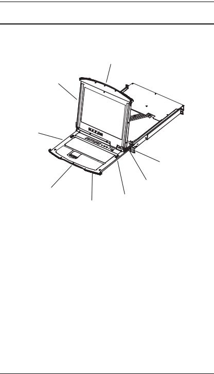
Front View
1
2
3
|
|
8 |
||
|
|
|
||
|
|
|
|
7 |
|
4 |
|
|
|
|
|
|
|
6 |
|
|
|
||
|
|
5 |
||
|
|
|
|
|
No. |
Component |
|
|
Description |
|
|
|
|
|
1 |
Upper Handle |
Pull to slide the LCD module out; push to slide the module in. |
||
|
|
See Opening the Console, page 21, for details on sliding the |
||
|
|
console in and out. |
||
|
|
|
|
|
2 |
LCD Module |
See LCD Module, page 10. |
||
|
|
|
|
|
3 |
Keyboard Module |
See Keyboard Module, page 9. |
||
|
|
|
|
|
4 |
Lower Handle |
Pull to slide the keyboard module out. See Opening the |
||
|
|
Console, page 21, for more details on sliding the console in |
||
|
|
and out. |
||
|
|
|
|
|
5 |
Power LED |
Lights (blue) to indicate that the unit is receiving power. |
||
|
|
|
|
|
6 |
Keyboard |
These catches (one on each side) release the keyboard |
||
|
Release Catch |
module so you can slide it away. |
||
|
|
|
|
|
7 |
LCD Release |
These catches (one on each side) release the LCD module |
||
|
Catch |
so you can slide it away. |
||
|
|
|
|
|
8 |
Rack Mounting |
The rack mounting tabs located at each corner of the unit |
||
|
Tabs |
secure the chassis to a system rack. See Standard Rack |
||
|
|
Mounting, page 14, for details. |
||
|
|
|
|
|
8
Chapter 1. Introduction
Keyboard Module
1
9
2 |
8 |
|
3
|
|
4 |
|
7 |
|
|
5 |
6 |
|
|
|
|
||
|
|
|
|
|
|
|
|
||
No. |
Component |
Description |
||
|
|
|
||
1 |
Port LEDs |
An On Line LED lights to indicate that the device attached |
||
|
|
to its corresponding port is up and running. |
||
|
|
A Selected LED lights to indicate that the computer |
||
|
|
attached to its corresponding port has the KVM focus. |
||
|
|
|
|
|
2 |
Keyboard |
Standard 105-key keyboard |
|
|
|
|
|
|
|
2 |
Touchpad |
Standard mouse touchpad |
|
|
|
|
|
||
4 |
Reset Switch |
Pressing and holding this switch in while powering on the |
||
|
|
unit causes the KL9108 / KL9116 to revert to the original |
||
|
|
factory installed firmware version – allowing you to recover |
||
|
|
from a failed firmware upgrade. |
|
|
|
|
Pressing and holding this switch in for more than three |
||
|
|
seconds performs a system reset. |
||
|
|
Note: The switch is recessed and must be pushed with a thin |
||
|
|
object - such as the end of a paper clip or a ballpoint pen. |
||
|
|
|
||
5 |
Port Selection |
The left button (DOWN), shifts the KVM focus down |
||
|
Switches |
through the ports (Port 7 → Port 6, etc.). After Port 1, it |
||
cycles back to the last port.
The right button (UP), shifts the KVM focus up through the ports. After the last port, it cycles to Port 1.
(Continues on next page.)
9
KL9108 / KL9116 User Manual
(Continued from previous page.)
No. |
Component |
Description |
|
|
|
6 |
Connection |
The LINK LED flashes when a remote client connects to |
|
LEDs |
the KVM switch. |
|
|
The 10/100 Mbps LED lights orange to indicate 10 Mbps |
|
|
data transmission speed. It lights green for 100 Mbps. |
|
|
|
7 |
External Mouse |
This PS/2-type mouse port is provided for users who prefer to |
|
Port |
use an external mouse. |
|
|
|
5 |
Lock LEDs |
The Num Lock, Caps Lock, Scroll Lock LEDs are located |
|
|
here. |
|
|
|
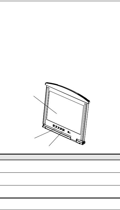
LCD Module
1
|
|
2 |
|
|
3 |
No. |
Component |
Description |
1 |
LCD Display |
To access the LCD monitor, slide the LCD module out and flip |
|
|
up the cover. See Opening the Console, page 21, for details |
|
|
on sliding the LCD module out. |
2 |
LCD Controls |
These buttons control the position and picture settings of the |
|
|
LCD display. See LCD OSD Configuration, page 27, for |
|
|
details. |
3 |
LCD On/Off |
Push this button to turn the LCD monitor on and off. The |
|
Button |
button lights when the LCD monitor is off to indicate that only |
|
|
the monitor is off – not the KVM switch itself.) |
10
Chapter 1. Introduction
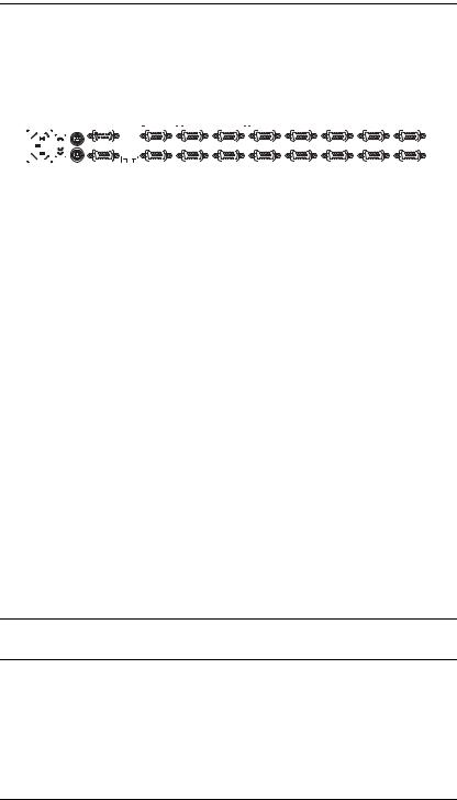
Rear View
|
1 |
|
|
2 |
3 |
|
|
|
|
|
|
|
|
4 |
|
|
|
|
|
|
|
|
|
|||||||||||||||||
|
|
|
|
|
|
|
|
|
|
|
|
|
|
|
|
|
|
|
|
|
|
|
|
|
|
|
|
|
|
|
|
|
|
|
|
|
|
|
|
|
|
|
|
|
|
|
|
|
|
|
|
|
|
|
|
|
|
|
|
|
|
|
|
|
|
|
|
|
|
|
|
|
|
|
|
|
|
|
|
|
|
|
|
|
|
|
|
|
|
|
|
|
|
|
|
|
|
|
|
|
|
|
|
|
|
|
|
|
|
|
|
|
|
|
|
|
|
|
|
|
|
|
|
|
|
|
|
|
|
|
|
|
|
|
|
|
|
|
|
|
|
|
|
|
|
|
|
|
|
|
|
|
|
|
|
|
|
|
|
|
|
|
|
|
|
|
|
|
|
|
|
|
|
|
|
|
|
|
|
|
|
|
|
|
|
|
|
|
|
|
|
|
|
|
|
|
|
|
|
|
|
|
|
|
|
|
|
|
|
|
|
|
|
|
|
|
|
|
|
|
|
|
|
|
|
|
|
|
|
|
|
|
|
|
|
|
|
|
|
|
|
|
|
|
|
|
|
|
|
|
|
|
|
|
|
|
|
|
|
|
|
|
|
|
|
|
|
|
|
|
|
|
|
|
|
|
|
|
|
|
|
|
|
|
|
|
|
|
|
|
|
|
|
|
|
|
|
|
|
|
|
|
|
|
|
|
|
|
|
|
|
|
|
|
|
|
|
|
|
|
|
|
|
|
|
|
|
|
|
|
|
|
|
|
|
|
|
|
|
|
|
|
|
|
|
|
|
|
|
|
|
|
|
|
|
|
|
|
|
|
|
|
|
|
|
|
|
|
|
5 |
6 |
|
|
|
No. |
Component |
Description |
|
|
|
1 |
Power Socket |
This is a standard 3-pin AC power socket. The power cord |
|
|
from an AC source plugs in here. |
|
|
|
2 |
Power Switch |
This is a standard rocker switch that powers the unit on and |
|
|
off. |
|
|
|
3 |
PON Port |
This connector is provided for a Power over the Net™ (PON) |
|
|
unit to plug into. A PON device allows computers attached to |
|
|
the KL9108 / KL9116 to be booted remotely over the LAN, |
|
|
WAN, or Internet. Contact your dealer for more details. |
|
|
|
4 |
KVM Ports |
The cables that link to the computers plug in here. |
|
|
Note: The shape of these 15-pin connectors has been |
|
|
specifically modified so that only custom KVM cables |
|
|
designed to work with this switch can plug in. (See Cables, |
|
|
page 6, for details.) Do NOT attempt to use ordinary 15-pin |
|
|
VGA connector cables to link these ports to the computers. |
|
|
|
5 |
External Console |
For flexibility and convenience, the KL9108 / KL9116 |
|
Ports |
supports an external KVM console. A custom console cable |
|
|
set is provided to attach the external console’s monitor, |
|
|
keyboard, and mouse. |
|
|
|
6 |
LAN Port |
The cable that connects the KL9108 / KL9116 to a LAN, |
|
|
WAN, or Internet plugs in here. |
|
|
|
*The KL9116 is pictured above. The KL9108 rear panel is the same as that of the KL9116, except that it has 8 KVM ports instead of 16.
11

KL9108 / KL9116 User Manual
This Page Intentionally Left Blank
12
Chapter 2
Hardware Setup
Before You Begin
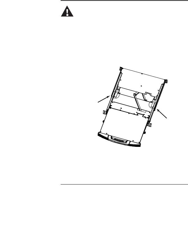
1.Important safety information regarding the placement of this device is provided on page 139. Please review it before proceeding.
2.Make sure that power to all the devices you will be connecting up has been turned off. You must unplug the power cords of any computers that have the Keyboard Power On function.
3.Packing material has been inserted to protect the KL9108 / KL9116 during shipping. Slide the LCD module out (see Opening the Console, page 21), until the packing material is visible. Remove the packing material before installing the unit, as shown in the diagram below.
13

KL9108 / KL9116 User Manual
Standard Rack Mounting
A standard rack mounting kit is provided with your KL9108 / KL9116. The kit enables the switch to be mounted in a rack with a depth of 42–77 cm.
L Brackets
 Side Mountng
Brackets
Note: 1. It takes two people to mount the switch: one to hold it in place, the other to screw it in.
2.The standard rack mounting kit does not include screws or cage nuts. If you need additional screws or cage nuts, contact your rack dealer.
3.Optional mounting kits – including single person Easy Installation kits – are available with a separate purchase. See Optional Rack Mounting, page 161, for details.
14

Chapter 2. Hardware Setup
To rack mount the switch, do the following:
1.While one person positions the switch in the rack and holds it in place, the second person loosely screws the front brackets to the rack.
2.While the first person still holds the switch in place, the second person slides the L brackets into the switch's side mounting brackets, from the rear until the bracket flanges contact the rack, then screws the L brackets to the rack.
3. After the L brackets have been secured, tighten the front bracket screws.
Note: Allow at least 5.1 cm on each side for proper ventilation, and at least 12.7 cm at the back for the power cord and cable clearance.
15

KL9108 / KL9116 User Manual
Single Stage Installation
In a Single Stage installation, there are no additional switches daisy chained down from the first unit. To set up a single stage installation, refer to the installation diagram on the following page (the numbers in the diagram correspond to the numbers of the installation steps) and do the following:
1.(Optional) If you choose to install an external console, plug your keyboard, monitor, and mouse into the Console Ports located on the KL9108 / KL9116’s rear panel. The ports are color coded and marked with an icon to identify themselves.
2.Using a KVM cable set (see Cables, page 6), plug the custom SPHD (yellow) connector into any available KVM port on the switch.
3.At the other end of the cable, plug the keyboard, video (blue), and mouse connectors into their respective ports on the computer.
4.Plug the cable from the LAN into the LAN port on the KL9108 / KL9116’s rear panel.
5.Connect the power cord provided with this package to an AC source and the KL9108 / KL9116’s power socket.
Repeat steps 2 – 5 for any other computers you wish to install.
After you are all cabled up, you can power on the switch. After the switch is powered on, power on the computers.
Note: Although the KL9116 is pictured in the diagram, the installation process is the same for the KL9108.
16

Chapter 2. Hardware Setup
Single Stage Installation Diagram
3
5
2
4
1
17

KL9108 / KL9116 User Manual
Two Stage Installation
To expand the number of computers that can be controlled in your KVM installation, up to 8 (KL9108), or 16 (KL9116) additional KVM switches can be cascaded from the KL9108 / KL9116’s KVM ports. As many as 64 (KL9108) or 128 (KL9116) computers can be controlled in a complete two stage installation.
In a two stage installation, the KL9108 / KL9116 is considered the first stage unit; the cascaded switches are considered second stage units.
Note: The KVM switch shown in the installation example is the KH98.
See Supported KVM Switches, page 165, for a complete list of switches that can be cascaded from the KL9108 / KL9116.
To set up a two stage installation, refer to the Two Stage Installation diagram on the next page, and do the following:
1.Make sure that power to all the devices you will be connecting up, including all preexisting devices on the installation, have been turned off.
2.Use a KVM cable set (see Cables, page 6), to connect any available KVM Port on the First Stage unit to the Console ports of the Second Stage unit.
3.Use KVM cable sets (as described in the Cables section of the user manual for the cascaded KVM switch) to connect any available KVM port on the cascaded KVM switch to the keyboard, video, and mouse ports of the computers you are installing.
4.Plug the power cord that came with the cascaded KVM switch into its power socket, and then into an AC power source.
(Repeat Steps 2–4 for any additional KVM switches that you wish to cascade from the KL9108 / KL9116.)
5.Power on the KL9108 / KL9116.
6.Power on the cascaded KVM switches.
7.Power on the computers.
18
Loading...