


Z9NH-D12 Series
Z9NH-D12/FDR
Z9NH-D12/10G Z9NH-D12
Motherboard

E7357
First Edition V1
December 2012
Copyright © 2012 ASUSTeK COMPUTER INC. All Rights Reserved.
No part of this manual, including the products and software described in it, may be reproduced, transmitted, transcribed, stored in a retrieval system, or translated into any language in any form or by any means, except documentation kept by the purchaser for backup purposes, without the express written permission of ASUSTeK COMPUTER INC. (“ASUS”).
Product warranty or service will not be extended if: (1) the product is repaired, modified or altered, unless such repair, modification of alteration is authorized in writing byASUS; or (2) the serial number of the product is defaced or missing.
ASUS PROVIDES THIS MANUAL “AS IS” WITHOUT WARRANTY OF ANY KIND, EITHER EXPRESS OR IMPLIED, INCLUDING BUT NOT LIMITED TO THE IMPLIED WARRANTIES OR CONDITIONS OF MERCHANTABILITY OR FITNESS FOR A PARTICULAR PURPOSE. IN NO EVENT SHALL ASUS, ITS DIRECTORS, OFFICERS, EMPLOYEES OR AGENTS BE LIABLE FOR ANY INDIRECT, SPECIAL, INCIDENTAL, OR CONSEQUENTIAL DAMAGES (INCLUDING DAMAGES FOR LOSS OF PROFITS, LOSS OF BUSINESS, LOSS OF USE OR DATA, INTERRUPTION OF BUSINESS AND THE LIKE), EVEN IF ASUS HAS BEEN ADVISED OF THE POSSIBILITY OF SUCH DAMAGES ARISING FROM ANY DEFECT OR ERROR IN THIS MANUAL OR PRODUCT.
SPECIFICATIONS AND INFORMATION CONTAINED IN THIS MANUAL ARE FURNISHED FOR INFORMATIONAL USE ONLY, AND ARE SUBJECT TO CHANGE AT ANY TIME WITHOUT NOTICE, AND SHOULD NOT BE CONSTRUED AS A COMMITMENT BY ASUS. ASUS ASSUMES NO RESPONSIBILITY OR LIABILITY FOR ANY ERRORS OR INACCURACIES THAT MAY APPEAR IN THIS MANUAL, INCLUDING THE PRODUCTS AND SOFTWARE DESCRIBED IN IT.
Products and corporate names appearing in this manual may or may not be registered trademarks or copyrights of their respective companies, and are used only for identification or explanation and to the owners’ benefit, without intent to infringe.
ii

Contents
Notices....................................................................................................... |
viii |
Federal Communications Commission Statement........................... |
viii |
Canadian Department of Communications Statement...................... |
ix |
REACH ............................................................................................ |
ix |
ASUS Recycling/Takeback Services................................................. |
ix |
Australia statement notice................................................................. |
ix |
Safety information........................................................................................ |
x |
About this guide.......................................................................................... |
xi |
How this guide is organized............................................................... |
xi |
Z9NH-D12 series specifications summary.............................................. |
xiii |
Z9NH-D12 series specifications summary.............................................. |
xiv |
Chapter 1: |
Product introduction |
|
|
1.1 |
Welcome!....................................................................................... |
1-3 |
|
1.2 |
Package contents......................................................................... |
1-3 |
|
1.3 |
Serial number label....................................................................... |
1-5 |
|
1.4 |
Special features............................................................................ |
1-5 |
|
|
1.4.1 |
Product highlights............................................................ |
1-5 |
|
1.4.2 |
Innovative ASUS features................................................ |
1-7 |
Chapter 2: |
Hardware information |
|
|
2.1 |
Before you proceed...................................................................... |
2-3 |
|
2.2 |
Motherboard overview................................................................. |
2-4 |
|
|
2.2.1 |
Placement direction......................................................... |
2-4 |
|
2.2.2 |
Screw holes..................................................................... |
2-4 |
|
2.2.3 |
Motherboard layout.......................................................... |
2-5 |
|
2.2.4 |
Layout contents............................................................... |
2-7 |
2.3 |
Central Processing Unit (CPU).................................................... |
2-9 |
|
|
2.3.1 |
Installing the CPU............................................................ |
2-9 |
|
2.3.2 |
Intel LGA1356 Socket.................................................... |
2-10 |
|
2.3.3 |
Installing the CPU heatsink........................................... |
2-13 |
2.4 |
System memory.......................................................................... |
2-14 |
|
|
2.4.1 |
Overview........................................................................ |
2-14 |
|
2.4.2 |
Memory Configurations................................................. |
2-15 |
2.5 |
Expansion slots.......................................................................... |
2-17 |
|
|
2.5.1 |
Installing an expansion card.......................................... |
2-17 |
|
2.5.2 |
Configuring an expansion card...................................... |
2-17 |
iii

Contents
|
2.5.3 |
PCI Express x16 slot (x16 link) ...................................... |
2-18 |
|
2.5.4 |
Installing ASMB6 management board . .......................... |
2-19 |
2.6 |
Onboard LEDs............................................................................. |
2-20 |
|
2.7 |
Jumpers |
....................................................................................... |
2-22 |
2.8 |
Connectors.................................................................................. |
2-27 |
|
|
2.8.1 .................................................. |
Rear panel connectors |
2-27 |
|
2.8.2 ........................................................ |
Internal connectors |
2-29 |
Chapter 3: |
Powering up |
|
|
3.1 |
Starting up for the first time........................................................ |
3-3 |
|
3.2 |
Powering off the computer.......................................................... |
3-4 |
|
|
3.2.1 |
Using the OS shut down function.................................... |
3-4 |
|
3.2.2 |
Using the dual function power switch.............................. |
3-4 |
Chapter 4: |
BIOS setup |
|
|
4.1 |
Managing and updating your BIOS............................................. |
4-3 |
|
|
4.1.1 |
ASUS CrashFree BIOS 3 utility....................................... |
4-3 |
|
4.1.2 |
ASUS EZ Flash 2 Utility................................................... |
4-4 |
|
4.1.3 |
BUPDATER utility............................................................ |
4-5 |
4.2 |
BIOS setup program..................................................................... |
4-7 |
|
|
4.2.1 |
BIOS menu screen.......................................................... |
4-8 |
|
4.2.2 |
Menu bar......................................................................... |
4-8 |
|
4.2.3 |
Menu items...................................................................... |
4-9 |
|
4.2.4 |
Submenu items................................................................ |
4-9 |
|
4.2.5 |
Navigation keys............................................................... |
4-9 |
|
4.2.6 |
General help.................................................................... |
4-9 |
|
4.2.7 |
Configuration fields.......................................................... |
4-9 |
|
4.2.8 |
Pop-up window................................................................ |
4-9 |
|
4.2.9 |
Scroll bar......................................................................... |
4-9 |
4.3 |
Main menu................................................................................... |
4-10 |
|
|
4.3.1 |
System Date [Day xx/xx/xxxx]....................................... |
4-10 |
|
4.3.2 |
System Time [xx:xx:xx].................................................. |
4-10 |
4.4 |
Advanced menu.......................................................................... |
4-11 |
|
|
4.4.1 |
CPU Configuration......................................................... |
4-12 |
|
4.4.2 |
CPU Power Management Configuration....................... |
4-14 |
|
4.4.3 |
Chipset Configuration.................................................... |
4-16 |
iv

Contents
|
4.4.4 |
PCH SATAConfiguration............................................... |
4-22 |
|
4.4.5 |
PCH SCU Configuration................................................ |
4-23 |
|
4.4.6 |
PCI Subsystem Settings................................................ |
4-23 |
|
4.4.7 |
USB Configuration......................................................... |
4-27 |
|
4.4.8 |
Trusted Computing........................................................ |
4-28 |
|
4.4.9 |
ACPI Settings................................................................ |
4-29 |
|
4.4.10 |
WHEAConfiguration...................................................... |
4-30 |
|
4.4.11 |
APM setting................................................................... |
4-30 |
|
4.4.12 |
Serial Port Console Redirection.................................... |
4-31 |
|
4.4.13 |
Onboard LAN Configuration.......................................... |
4-34 |
|
4.4.14 |
ME Subsystem.............................................................. |
4-34 |
|
4.4.15 |
Onboard Devices Configuration.................................... |
4-35 |
|
4.4.16 |
Runtime Error Logging.................................................. |
4-35 |
4.6 |
Event Logs menu........................................................................ |
4-36 |
|
|
4.6.1 |
Change Smbios Event Log Settings.............................. |
4-36 |
4.7 |
Boot menu................................................................................... |
4-38 |
|
4.8 |
Monitor menu.............................................................................. |
4-40 |
|
4.9 |
Security menu............................................................................. |
4-42 |
|
4.10 |
Tool menu.................................................................................... |
4-43 |
|
4.11 |
Exit menu..................................................................................... |
4-44 |
|
Chapter 5: |
RAID configuration |
|
|
5.1 |
Setting up RAID............................................................................ |
5-3 |
|
|
5.1.1 |
RAID definitions............................................................... |
5-3 |
|
5.1.2 |
Installing hard disk drives................................................ |
5-4 |
|
5.1.3 |
Setting the RAID item in BIOS......................................... |
5-4 |
|
5.1.4 |
RAID configuration utilities.............................................. |
5-4 |
5.2 |
LSI Software RAID Configuration Utility .................................... |
5-5 |
|
|
5.2.1 |
Creating a RAID set......................................................... |
5-6 |
|
5.2.2 |
Adding or viewing a RAID configuration........................ |
5-12 |
|
5.2.3 |
Initializing the virtual drives............................................ |
5-13 |
|
5.2.4 |
Rebuilding failed drives................................................. |
5-17 |
|
5.2.5 |
Checking the drives for data consistency...................... |
5-19 |

Contents
5.2.6 |
Deleting a RAID configuration....................................... |
5-22 |
5.2.7 |
Selecting the boot drive from a RAID set...................... |
5-23 |
5.2.8 |
Enabling WriteCache..................................................... |
5-24 |
5.3Intel® Rapid Storage Technology enterprise SCU/SATA Option ROM Utility.........................................................................................5-25
5.3.1 |
Creating a RAID set....................................................... |
5-27 |
5.3.2 |
Creating a Recovery set................................................ |
5-28 |
5.3.3 |
Deleting a RAID set....................................................... |
5-30 |
5.3.4 |
Resetting disks to Non-RAID......................................... |
5-31 |
5.3.5 |
Exiting the Intel® Rapid Storage Technology utility........ |
5-32 |
5.3.6 |
Rebuilding the RAID...................................................... |
5-32 |
5.3.7 |
Setting the Boot array in the BIOS Setup Utility............ |
5-34 |
5.4Intel® Rapid Storage Technology enterprise Utility (Windows)5-35
|
5.4.1 |
Creating a RAID set....................................................... |
5-36 |
|
5.4.2 |
Change Volume Type.................................................... |
5-38 |
|
5.4.3 |
Delete volume................................................................ |
5-39 |
|
5.4.4 |
Preferences................................................................... |
5-40 |
Chapter 6: |
Driver installation |
|
|
6.1 |
RAID driver installation................................................................ |
6-3 |
|
|
6.1.1 |
Creating a RAID driver disk............................................. |
6-3 |
|
6.1.2 |
Installing the RAID controller driver................................. |
6-6 |
6.2 |
Intel® chipset device software installation............................... |
6-16 |
|
6.3 |
Intel@ Network Connections Software installation.................. |
6-19 |
|
6.4 |
VGA driver installation............................................................... |
6-22 |
|
6.5 |
Intel® C600 Series Chipset SCU SATA RAID Drivers............... |
6-25 |
|
6.6 |
Intel® C600 MEI NULL HECI Driver............................................ |
6-26 |
|
6.7Intel® Rapid Storage Technology enterprise 3.1 installation.. 6-27
6.8 |
Intel® WG82574L Gigabit Adapters Driver installation............ |
6-30 |
vi

6.9 |
Management applications and utilities installation................. |
6-34 |
|
|
6.9.1 |
Running the support DVD.............................................. |
6-34 |
|
6.9.2 |
Drivers menu................................................................. |
6-34 |
|
6.9.3 |
Utilities menu................................................................. |
6-35 |
|
6.9.4 |
Make disk menu............................................................ |
6-35 |
|
6.9.5 |
Contact information....................................................... |
6-35 |
Appendix: |
Reference information |
|
|
A.1 |
Z9NH-D12/FDR block diagram..................................................... |
A-2 |
|
A.2 |
Z9NH-D12/10G block diagram..................................................... |
A-3 |
|
A.3 |
Z9NH-D12 block diagram............................................................. |
A-4 |
|
ASUS contact information........................................................................ |
A-5 |
||
ASUS contact information........................................................................ |
A-6 |
||
ASUS contact information........................................................................ |
A-7 |
||
vii

Notices
Federal Communications Commission Statement
This device complies with Part 15 of the FCC Rules. Operation is subject to the following two conditions:
•This device may not cause harmful interference.
•This device must accept any interference received including interference that may cause undesired operation.
This equipment has been tested and found to comply with the limits for a Class A digital device, pursuant to Part 15 of the FCC Rules. These limits are designed to provide reasonable protection against harmful interference in a residential installation. This equipment generates, uses and can radiate radio
frequency energy and, if not installed and used in accordance with manufacturer’ s instructions, may cause harmful interference to radio communications. However, there is no guarantee that interference will not occur in a particular installation. If this equipment does cause harmful interference to radio or television reception, which can be determined by turning the equipment off and on, the user is encouraged to try to correct the interference by one or more of the following measures:
•Reorient or relocate the receiving antenna.
•Increase the separation between the equipment and receiver.
•Connect the equipment to an outlet on a circuit different from that to which the receiver is connected.
•Consult the dealer or an experienced radio/TV technician for help.
The use of shielded cables for connection of the monitor to the graphics card is required to assure compliance with FCC regulations. Changes or modifications to this unit not expressly approved by the party responsible for compliance could void the user’s authority to operate this equipment.
viii
Canadian Department of Communications Statement
This digital apparatus does not exceed the Class B limits for radio noise emissions from digital apparatus set out in the Radio Interference Regulations of the Canadian Department of Communications.
This class A digital apparatus complies with Canadian ICES-003.
REACH
Complying with the REACH (Registration, Evaluation, Authorisation, and Restriction of Chemicals) regulatory framework, we published the chemical substances in our products at ASUS REACH website at http://csr.asus.com/english/REACH.htm.
DO NOT throw the motherboard in municipal waste. This product has been designed to enable proper reuse of parts and recycling. This symbol of the crossed out wheeled bin indicates that the product (electrical and electronic equipment) should not be placed in municipal waste. Check local regulations for disposal of electronic products.
DO NOT throw the mercury-containing button cell battery in municipal waste. This symbol of the crossed out wheeled bin indicates that the battery should not be placed in municipal waste.
ASUS Recycling/Takeback Services
ASUS recycling and takeback programs come from our commitment to the highest standards for protecting our environment. We believe in providing solutions for you to be able to responsibly recycle our products, batteries, other components as well as the packaging materials. Please go to http://csr.asus.com/english/Takeback.htm for detailed recycling information in different regions.
Australia statement notice
From 1 January 2012 updated warranties apply to all ASUS products, consistent with the Australian Consumer Law. For the latest product warranty details please visit http://support.asus.com. Our goods come with guarantees that cannot be excluded under the Australian Consumer Law. You are entitled to a replacement or refund for a major failure and compensation for any other reasonably foreseeable loss or damage. You are also entitled to have the goods repaired or replaced if the goods fail to be of acceptable quality and the failure does not amount to a major failure.
If you require assistance please call ASUS Customer Service 1300 2787 88 or visit us at http://support.asus.com.
ix
Safety information
Electrical Safety
•Before installing or removing signal cables, ensure that the power cables for the system unit and all attached devices are unplugged.
•Topreventelectricalshockhazard,disconnectthepowercablefromtheelectrical outlet before relocating the system.
•When adding or removing any additional devices to or from the system, ensure that the power cables for the devices are unplugged before the signal cables are connected. If possible, disconnect all power cables from the existing system before you add a device.
•If the power supply is broken, do not try to fix it by yourself. Contact a qualified service technician or your dealer.
Operation Safety
•Any mechanical operation on this server must be conducted by certified or experienced engineers.
•Before operating the server, carefully read all the manuals included with the server package.
•Before using the server, ensure all cables are correctly connected and the power cables are not damaged. If any damage is detected, contact your dealer as soon as possible.
•To avoid short circuits, keep paper clips, screws, and staples away from connectors, slots, sockets and circuitry.
•Avoid dust, humidity, and temperature extremes. Place the server on a stable surface.
This product is equipped with a three-wire power cable and plug for the user’s safety. Use the power cable with a properly grounded electrical outlet to avoid electrical shock.
Lithium-Ion Battery Warning
CAUTION! Danger of explosion if battery is incorrectly replaced. Replace only with the same or equivalent type recommended by the manufacturer. Dispose of used batteries according to the manufacturer’s instructions.
CD-ROM Drive Safety Warning
CLASS 1 LASER PRODUCT
Heavy System
CAUTION! This server system is heavy. Ask for assistance when moving or carrying the system.
About this guide
This user guide contains the information you need when installing and configuring the motherboard.
How this guide is organized
This user guide contains the following parts:
•Chapter 1: Product introduction
This chapter describes the features of the motherboard and the new technologies it supports.
•Chapter 2: Hardware information
This chapter lists the hardware setup procedures that you have to perform when installing system components. It includes description of the switches, jumpers, and connectors on the motherboard.
•Chapter 3: Powering up
This chapter describes the power up sequence and ways of shutting down the system.
•Chapter 4: BIOS setup
This chapter tells how to change system settings through the BIOS Setup menus. Detailed descriptions of the BIOS parameters are also provided.
•Chapter 5: RAID configuration
This chapter provides instructions for setting up, creating, and configuring
RAID sets using the available utilities.
•Chapter 6: Driver installation
This chapter provides instructions for installing the necessary drivers for different system components.
•Appendix: Reference information
This appendix includes additional information that you may refer to when configuring the motherboard.
xi
Conventions
To ensure that you perform certain tasks properly, take note of the following symbols used throughout this manual.
DANGER/WARNING: Information to prevent injury to yourself when trying to complete a task.
CAUTION: Information to prevent damage to the components when trying to complete a task.
IMPORTANT: Instructions that you MUST follow to complete a task. NOTE: Tips and additional information to help you complete a task.
Typography
Bold text |
Indicates a menu or an item to select. |
Italics |
Used to emphasize a word or a phrase. |
<Key> |
Keys enclosed in the less-than and greater-than |
|
sign means that you must press the enclosed key. |
|
Example: <Enter> means that you must press |
|
the Enter or Return key. |
<Key1+Key2+Key3> |
If you must press two or more keys simultaneously, |
|
the key names are linked with a plus sign (+). |
|
Example: <Ctrl+Alt+D> |
Command |
Means that you must type the command |
|
exactly as shown, then supply the required |
|
item or value enclosed in brackets. |
|
Example: At the DOS prompt, type the |
|
command line: format A:/S |
References |
|
Refer to the following sources for additional information, and for product and software updates.
1.ASUS Server Web-based Management (ASWM) user guide
This manual tells how to set up and use the proprietary ASUS server management utility.
2.ASUS websites
The ASUS websites worldwide provide updated information for all ASUS hardware and software products. Refer to the ASUS contact information.
xii
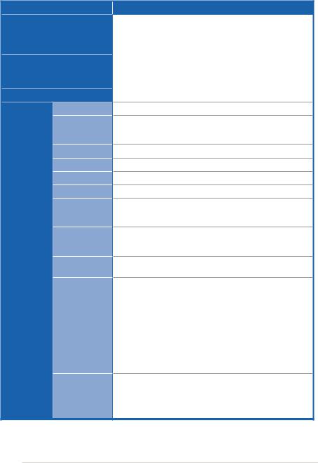
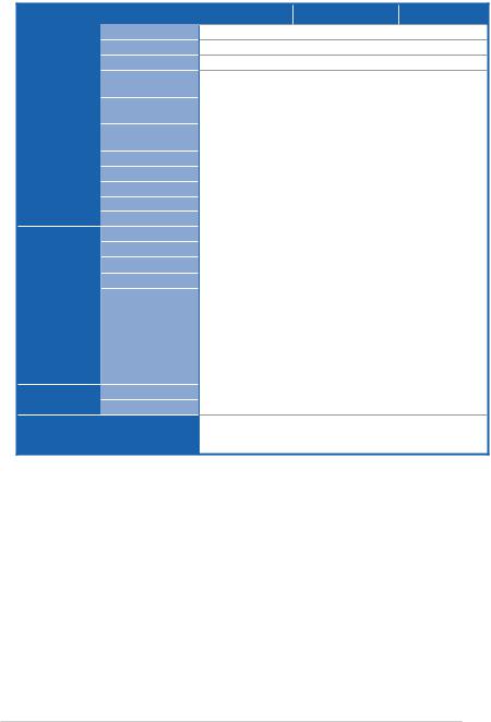
Z9NH-D12 series specifications summary
Model Name
Processor / System Bus
Core Logic
Form Factor
ASUS Features |
FAN speed control |
|
Rack Optimized |
|
(Dedicated for |
|
Rack) |
|
ASWM Enterprise |
|
Total Slots |
Memory |
|
|
Voltage |
|
Capacity |
|
Memory Type |
|
Memory Size* |
|
Total PCI/PCI-X/ |
Expansion |
|
Slots |
PCI-E Slots |
Storage |
SATA Controller |
SAS Controller
Z9NH-D12/ FDR |
|
Z9NH-D12/ 10G |
Z9NH-D12 |
|
2 * LGA 1356 |
|
|
|
|
|
|
|
||
Intel® Xeon® processor E5-2400 product family |
|
|
||
|
|
|
|
|
QPI 6.4 / 7.2 / 8.0 GT/s |
|
|
|
|
|
|
|
|
|
Intel® C602-A PCH |
|
Intel® C602-A PCH |
Intel® C602-A |
|
Mellanox |
|
Mellanox ConnectX-3 |
PCH |
|
|
|
|
||
ConnectX-3 FDR |
|
10GbE |
|
|
|
|
|
|
|
Proprietary, 6.3” x 16.7
V
V
V
12 (3-channel per CPU, 6 DIMM per CPU)
1.5V/1.35V
Maximum up to 384GB
DDR3 800/1066/1333/1600 RDIMM
DDR3 1066/1333 ECC UDIMM/ Non-ECC UDIMM
DDR3 1066/1333 LR-DIMM
2GB, 4GB, 8GB, 16GB * (RDIMM) 2GB, 4GB, 8GB * (UDIMM)
8 GB, 16GB, 32GB * (LRDIMM)
1 * PCI-E x16 (X16 Gen3 Link)
Intel® C602-A: <AHCI>
2 SATA3Gb/s ports; 2 SATA6Gb/s ports
Intel® RSTe (for Windows only) (Support software RAID 0, 1, 10 & 5) LSI® MegaRAID (for Linux/Windows) (Support software RAID 0, 1, 10)
<SCU>
4 SATA 3Gb/s ports
Intel® RSTe (for Windows only)
(Support software RAID 0, 1, 10 & 5 for all SATA ports)
Optional kits:
ASUS PIKE 2008 8-port SAS 6G RAID card ASUS PIKE 2008/IMR 8-port SAS 6G RAID card ASUS PIKE 2108 8-port SAS 6G HW RAID card
(support with riser card)
(continued on the next page)
xiii
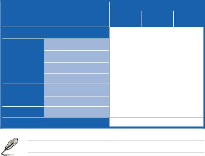
Z9NH-D12 series specifications summary
Model Name |
|
|
|
Graphic |
VGA |
Onboard I/O |
TPM header |
Connectors |
PSU Connector |
|
Device Power |
|
Connector |
|
Management |
|
Connector |
|
USB Connectors |
|
Fan Header |
|
SMBus |
|
Chassis Intruder |
|
Front LAN LED |
|
Serial Port Header |
Rear I/O |
External Serial Port |
Connectors |
External USB Port |
|
QSFP Port |
|
VGA Port |
|
RJ-45 |
Monitoring |
|
CPU Temperature |
|
||
Environment |
|
FAN RPM |
|
|
Z9NH-D12/ FDR |
Z9NH-D12/ 10G |
Z9NH-D12 |
Aspeed AST2300 with 16MB VRAM 1
2 * 20-pin ATX power connector
4-pin power connector
Onboard socket for management card |
|
||
|
|
|
|
1 |
* USB connector (Type A USB socket) |
|
|
1 |
* USB pin header |
|
|
4 |
* 4pin |
|
|
2 |
|
|
|
1 |
(in AUXPANEL 1) |
|
|
- |
|
|
|
- |
|
|
|
1 |
|
|
|
2 |
|
|
|
1 |
|
1 |
- |
1 |
|
|
|
- 2 * Intel 82574L |
- 2 * Intel 82574L + |
- 2 * Intel |
|
+ 1 * Mgmt LAN |
1 * Mgmt LAN |
82574L + 1 * |
|
- 1 * Single |
- 1 * Single |
Mgmt LAN |
|
|
|||
Port Mellanox |
Port Mellanox |
|
|
ConnectX-3 FDR |
ConnectX-3 |
|
|
infiniband with |
10GbE with QSFP |
|
|
QSFP interface |
interface |
|
|
V |
|
|
|
V |
|
|
|
Operation temperature: 10°C ~ 35°C Non operation temperature: -40°C ~ 70°C
Non operation humidity: 20% ~ 90% ( Non condensing)
*Refer to ASUS Server AVL for latest update.
**Specifications are subject to change without notice.
xiv
This chapter describes the motherboard |
|
1 |
features and the new technologies it supports. |
|
|
|
|
Product |
|
introduction |
|

|
|
Chapter summary |
1 |
|
|
|
|
1.1 |
Welcome!....................................................................................... |
1-3 |
1.2 |
Package contents......................................................................... |
1-3 |
1.3 |
Serial number label....................................................................... |
1-5 |
1.4 |
Special features............................................................................ |
1-5 |
ASUS Z9NH-D12 Series

1.1Welcome!
Thank you for buying an ASUS® Z9NH-D12 Series motherboard!
The motherboard delivers a host of new features and latest technologies, making it another standout in the long line of ASUS quality motherboards!
Before you start installing the motherboard, and hardware devices on it, check the items in your package with the list below.
1.2Package contents
Check your motherboard package for the following items.
Z9NH-D12 Series
Standard Bulk Pack
ASMB6-iKVM module
|
Support CD |
|
Application CD |
Infiniband SDVD |
|
ASWM Enterprise SDVD |
||
|
||
|
ASMB6-iKVM SDVD |
|
Documentation |
Motherboard User Guide |
|
ASMB6-iKVM User Guide |
||
|
||
Cable |
Thermistor |
|
Packing Qty. |
|
Z9NH-D12/ |
Z9NH- |
Z9NH-D12 |
|
FDR |
D12/10G |
||
|
|||
1 |
1 |
1 |
|
|
|
|
|
1 |
1 |
1 |
|
|
|
|
|
1 |
1 |
|
|
1 |
1 |
1 |
|
1 |
1 |
1 |
|
|
|
|
|
1 |
1 |
1 |
|
|
|
|
|
1 |
1 |
1 |
|
|
|
|
|
2 |
2 |
2 |
|
|
|
|
10 pc per carton
ASUS Z9NH-D12 Series |
1-3 |
ASMB6-iKVM module
|
Support CD |
|
Application CD |
Infiniband SDVD |
|
|
ASWM Enterprise SDVD |
|
|
ASMB6-iKVM SDVD |
|
Documentation |
Motherboard User Guide |
|
ASMB6-iKVM User Guide |
||
|
||
Cable |
Thermistor |
|
Packing Qty. |
|
Standard Gift Box |
|
||
Z9NH-D12/ Z9NH- |
Z9NH-D12 |
||
FDR |
D12/10G |
||
|
|||
1 |
1 |
1 |
|
|
|
|
|
1 |
1 |
1 |
|
|
|
|
|
1 |
1 |
|
|
|
|
|
|
1 |
1 |
1 |
|
|
|
|
|
1 |
1 |
1 |
|
1 |
1 |
1 |
|
|
|
|
|
1 |
1 |
1 |
|
|
|
|
|
2 |
2 |
2 |
|
|
|
|
|
1 pc per carton
If any of the above items is damaged or missing, contact your retailer.
1-4 |
Chapter 1: Product introduction |

1.3Serial number label
Before requesting support from the ASUS Technical Support team, you must take note of the motherboard's serial number containing 12 characters xxS2xxxxxxxx shown as the figure below. With the correct serial number of the product,ASUS
Technical Support team members can then offer a quicker and satisfying solution to your problems.
Z9NH-D12 |
Made |
|
in |
|
China |
xxS2xxxxxxxx |
|
1.4Special features
1.4.1Product highlights
Latest Processor Technology
The motherboard supports the latest Intel Xeon® processor E5-2400 product family in LGA 1356 package with integrated memory controller to support 3 channel (6 DIMM per CPU) DDR3 memory. Intel Xeon® processor E5-2400 product family supports Intel QuickPath Interconnect (QPI) with a system bus of up to 8.0GT/s.
Optimized Intel® Turbo Boost Technology
Optimized Intel® Turbo Boost Technology further optimizes the processor’s performance and automatically allows it to run faster than the marked frequency if it is operating below power, temperature, and current limits.
Intel® Hyper Threading
The thread-level parallelism on each processor makes more efficient use of the processor resources, higher processing throughout and improved performance on today's multi-threaded software.
Intel® EM64T
The motherboard supports Intel® processors with the Intel® EM64T (Extended Memory 64 Technology). The Intel® EM64T feature allows your computer to run on 64-bit operating systems and access larger amounts of system memory for faster and more efficient computing.
ASUS Z9NH-D12 Series |
1-5 |
DDR3 memory support
The Z9NH-D12 supports DDR3 memory that features data transfer rates of
1600/1333/1066 MHz to meet the higher bandwidth requirements of server and workstation applications. The 3-channel DDR3 architecture boosts system
performance, eliminating bottlenecks with peak bandwidth of up to 37.5GB/s. This voltage reduction limits the power consumption and heat generation of DDR3 which makes it an ideal memory solution. Also, the motherboard can support LRDIMM (Load reduced DIMM) which uses a specially designed buffer to reduce the data load to a single load and can increase overall server system memory capacity.
PCIe 3.0
The motherboard supports the latest PCIe 3.0 device, which doubles the delivered bandwidth of PCIe 2.0. This enhances system performance while still providing backward compatibility to PCIe 2.0.
Intel® 82574L Gigabit LAN Solution
This motherboard features the built-in dual server class Intel® Gigabit LAN ports, which helps reduce CPU usage, thus increasing throughput to achieve highlyreliable network connections, outstanding performance, and better support for diverse operating systems.
Intel® 82574L chipset is VMware-certified to support the virtualization technology.
Enhanced Intel SpeedStep Technology (EIST)
The Enhanced Intel SpeedStep Technology (EIST) intelligently manages the CPU resources by automatically adjusting the CPU voltage and core frequency depending on the CPU loading and system speed or power requirement.
Serial ATA II technology
The motherboard supports the Serial ATA II 3 Gb/s technology through the Serial ATA interface and Intel® C602 chipset. The SerialATAII specification provides twice the bandwidth of the current Serial ATA products with a host of new features, including Native Command Queuing (NCQ), Power Management (PM)
ImplementationAlgorithm, and Hot Swap. SerialATAallows thinner, more flexible cables with lower pin count and reduced voltage requirements.
Serial ATA III technology
The motherboard supports the Serial ATA III technology through the Serial ATA interface and Intel® C602 chipset, delivering up to 6Gb/s data transfer rates. Additionally, get enhanced scalability, faster data retrieval, double the bandwidth of current bus systems.
1-6 |
Chapter 1: Product introduction |
USB 2.0 technology
The motherboard implements the Universal Serial Bus (USB) 2.0 specification, dramatically increasing the connection speed from the 12 Mbps bandwidth on USB 1.1 to a fast 480 Mbps on USB 2.0. USB 2.0 is backward compatible with USB 1.1.
Temperature, fan, and voltage monitoring
The CPU temperature is monitored to prevent overheating and damage. The system fan rotations per minute (RPM) is monitored for timely failure detection. The chip monitors the voltage levels to ensure stable supply of current for critical components.
1.4.2Innovative ASUS features
ASUS Fan Speed control technology
The ASUS Fan Speed control technology smartly adjusts the fan speeds according to the system loading to ensure quiet, cool, and efficient operation.
PIKE (Proprietary I/O Kit Expansion)
PIKE is an on-demand upgrade kit for users. This ASUS unique feature enables users to choose their preferred I/O solutions. ASUS provides multiple SAS solutions for different segments and purposes and PIKE saves lots of validation efforts and hardware cost for end users.
ASUS Z9NH-D12 Series |
1-7 |

1-8 |
Chapter 1: Product introduction |
This chapter lists the hardware setup procedures that you have to perform when installing system components. It includes description of the jumpers and connectors on the motherboard.
Chapter 2:
Hardware2 information

|
|
Chapter summary |
2 |
|
|
|
|
2.1 |
Before you proceed...................................................................... |
2-3 |
2.2 |
Motherboard overview................................................................. |
2-4 |
2.3 |
Central Processing Unit (CPU).................................................... |
2-9 |
2.4 |
System memory.......................................................................... |
2-14 |
2.5 |
Expansion slots.......................................................................... |
2-17 |
2.6 |
Onboard LEDs............................................................................. |
2-20 |
2.7 |
Jumpers....................................................................................... |
2-22 |
2.8 |
Connectors.................................................................................. |
2-27 |
ASUS Z9NH-D12 Series
2.1Before you proceed
Take note of the following precautions before you install motherboard components or change any motherboard settings.
•Unplug the power cord from the wall socket before touching any component.
•Use a grounded wrist strap or touch a safely grounded object or a metal object, such as the power supply case, before handling components to avoid damaging them due to static electricity.
•Hold components by the edges to avoid touching the ICs on them.
•Whenever you uninstall any component, place it on a grounded antistatic pad or in the bag that came with the component.
•Before you install or remove any component, ensure that the power supply is switched off or the power cord is detached from the power supply. Failure to do so may cause severe damage to the motherboard, peripherals, and/or components.
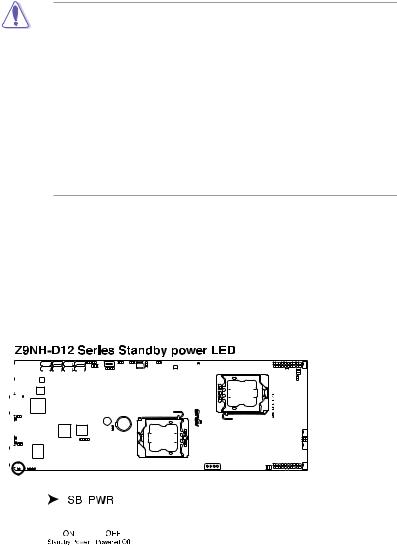
Standby Power LED (SB_PWR1)
The motherboard comes with a standby power LED. The green LED lights up to indicate the system AC power cable plug or not. This is a reminder that you should shut down the system and unplug the power cable before removing or plugging
in any motherboard component. The illustration below shows the location of the onboard LED.
|
|
|
|
|
|
|
|
|
|
|
|
|
|
|
|
|
|
|
|
|
|
|
|
|
|
|
|
|
|
|
|
|
|
|
|
|
|
|
|
|
|
|
|
|
|
|
|
|
|
|
|
|
|
|
|
|
|
|
|
|
|
|
|
|
|
|
|
|
|
|
|
|
|
|
|
|
|
|
|
|
|
|
|
|
|
|
|
|
|
|
|
|
|
|
|
|
|
|
|
|
|
|
|
|
|
|
|
|
|
|
|
|
|
|
|
|
|
|
|
|
|
|
|
|
|
|
|
|
|
|
|
|
|
|
|
|
|
|
|
|
|
|
|
|
|
|
|
|
|
|
|
|
|
|
|
|
|
|
|
|
|
|
|
|
|
|
|
|
|
|
|
|
|
|
|
|
|
|
|
|
|
|
|
|
|
|
|
|
|
|
|
|
|
|
|
|
|
|
|
|
|
|
|
|
|
|
|
|
|
|
|
|
|
|
|
|
|
|
|
|
|
|
|
|
|
|
|
|
|
|
|
|
|
|
|
|
|
|
|
|
|
|
|
|
|
|
|
|
|
|
|
|
|
|
|
|
|
|
|
|
|
|
|
|
|
|
|
|
|
|
|
|
|
|
|
|
|
|
|
|
|
|
|
|
|
|
|
|
|
|
|
|
|
|
|
|
|
|
|
|
|
|
|
|
|
|
|
|
|
|
|
|
|
|
|
|
|
|
|
|
|
|
|
|
|
|
|
|
|
|
|
|
|
|
|
|
|
|
|
|
|
|
|
|
|
|
|
|
|
|
|
|
|
|
|
|
|
|
|
|
|
|
|
|
|
|
|
|
|
|
|
|
|
|
|
|
|
|
|
|
|
|
|
|
|
|
|
|
|
|
|
|
|
|
|
|
|
|
|
|
|
|
|
|
|
|
|
|
|
|
|
|
|
|
|
|
|
|
|
|
|
|
|
|
|
|
|
|
|
|
|
|
|
|
|
|
|
|
|
|
|
|
|
|
|
|
|
|
|
|
|
|
|
|
|
|
|
|
|
|
|
|
|
|
|
|
|
|
|
|
|
|
|
|
|
|
|
|
|
|
|
|
|
|
|
|
|
|
|
|
|
|
|
|
|
|
|
|
|
|
|
|
|
|
|
|
|
|
|
|
|
|
|
|
|
|
|
|
|
|
|
|
|
|
|
|
|
|
|
|
|
|
|
|
|
|
|
|
|
|
|
|
|
|
|
|
|
|
|
ASUS Z9NH-D12 Series |
2-3 |
||||||||||||||||||||||||||||||||||||||||||||||||
2.2Motherboard overview
Before you install the motherboard, study the configuration of your chassis to ensure that the motherboard fits into it.
Ensure to unplug the chassis power cord before installing or removing the motherboard. Failure to do so can cause you physical injury and damage motherboard components!
2.2.1Placement direction
When installing the motherboard, ensure that you place it into the chassis in the correct orientation. The edge with external ports goes to the rear part of the chassis as indicated in the image below.
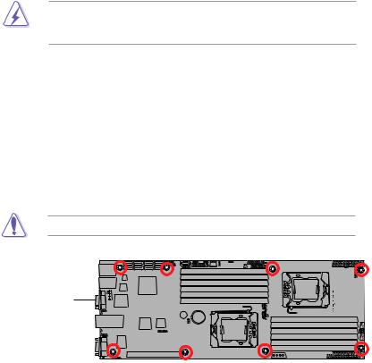
2.2.2Screw holes
Place eight (8) screws into the holes indicated by the circles to secure the motherboard to the chassis.
DO NOT overtighten the screws! Doing so can damage the motherboard.
Place this side towards  the rear of the chassis
2-4 |
Chapter 2: Hardware information |

2.2.3Motherboard layout
Z9NH-D12/FDR |
|
|
|
|
Z9NH-D12/10G |
|
|
|
|
|||||||||||||||||||||||||||||||||||||||||||||||||||||||||||||||||||||||||||||
|
|
|
|
|
|
|
|
|
|
|
|
|
|
|
|
|
|
|
|
|
|
|
|
|
|
|
|
|
|
|
|
|
|
|
|
|
|
|
|
|
|
|
|
|
|
|
|
|
|
|
|
|
|
|
|
|
|
|
|
|
|
|
|
|
|
|
|
|
|
|
|
|
|
|
|
|
|
|
|
|
|
|
|
|
|
|
|
|
|
|
|
|
|
|
|
|
|
|
|
|
|
|
|
|
|
|
|
|
|
|
|
|
|
|
|
|
|
|
|
|
|
|
|
|
|
|
|
|
|
|
|
|
|
|
|
|
|
|
|
|
|
|
|
|
|
|
|
|
|
|
|
|
|
|
|
|
|
|
|
|
|
|
|
|
|
|
|
|
|
|
|
|
|
|
|
|
|
|
|
|
|
|
|
|
|
|
|
|
|
|
|
|
|
|
|
|
|
|
|
|
|
|
|
|
|
|
|
|
|
|
|
|
|
|
|
|
|
|
|
|
|
|
|
|
|
|
|
|
|
|
|
|
|
|
|
|
|
|
|
|
|
|
|
|
|
|
|
|
|
|
|
|
|
|
|
|
|
|
|
|
|
|
|
|
|
|
|
|
|
|
|
|
|
|
|
|
|
|
|
|
|
|
|
|
|
|
|
|
|
|
|
|
|
|
|
|
|
|
|
|
|
|
|
|
|
|
|
|
|
|
|
|
|
|
|
|
|
|
|
|
|
|
|
|
|
|
|
|
|
|
|
|
|
|
|
|
|
|
|
|
|
|
|
|
|
|
|
|
|
|
|
|
|
|
|
|
|
|
|
|
|
|
|
|
|
|
|
|
|
|
|
|
|
|
|
|
|
|
|
|
|
|
|
|
|
|
|
|
|
|
|
|
|
|
|
|
|
|
|
|
|
|
|
|
|
|
|
|
|
|
|
|
|
|
|
|
|
|
|
|
|
|
|
|
|
|
|
|
|
|
|
|
|
|
|
|
|
|
|
|
|
|
|
|
|
|
|
|
|
|
|
|
|
|
|
|
|
|
|
|
|
|
|
|
|
|
|
|
|
|
|
|
|
|
|
|
|
|
|
|
|
|
|
|
|
|
|
|
|
|
|
|
|
|
|
|
|
|
|
|
|
|
|
|
|
|
|
|
|
|
|
|
|
|
|
|
|
|
|
|
|
|
|
|
|
|
|
|
|
|
|
|
|
|
|
|
|
|
|
|
|
|
|
|
|
|
|
|
|
|
|
|
|
|
|
|
|
|
|
|
|
|
|
|
|
|
|
|
|
|
|
|
|
|
|
|
|
|
|
|
|
|
|
|
|
|
|
|
|
|
|
|
|
|
|
|
|
|
|
|
|
|
|
|
|
|
|
|
|
|
|
|
|
|
|
|
|
|
|
|
|
|
|
|
|
|
|
|
|
|
|
|
|
|
|
|
|
|
|
|
|
|
|
|
|
|
|
|
|
|
|
|
|
|
|
|
|
|
|
|
|
|
|
|
|
|
|
|
|
|
|
|
|
|
|
|
|
|
|
|
|
|
|
|
|
|
|
|
|
|
|
|
|
|
|
|
|
|
|
|
|
|
|
|
|
|
|
|
|
|
|
|
|
|
|
|
|
|
|
|
|
|
|
|
|
|
|
|
|
|
|
|
|
|
|
|
|
|
|
|
|
|
|
|
|
|
|
|
|
|
|
|
|
|
|
|
|
|
|
|
|
|
|
|
|
|
|
|
|
|
|
|
|
|
|
|
|
|
|
|
|
|
|
|
|
|
|
|
|
|
|
|
|
|
|
|
|
|
|
|
|
|
|
|
|
|
|
|
|
|
|
|
|
|
|
|
|
|
|
|
|
|
|
|
|
|
|
|
|
|
|
|
|
|
|
|
|
|
|
|
|
|
|
|
|
|
|
|
|
|
|
|
|
|
|
|
|
|
|
|
|
|
|
|
|
|
|
|
|
|
|
|
|
|
|
|
|
|
|
|
|
|
|
|
|
|
|
|
|
|
|
|
|
|
|
|
|
|
|
|
|
|
|
|
|
|
|
|
|
|
|
|
|
|
|
|
|
|
|
|
|
|
|
|
|
|
|
|
|
|
|
|
|
|
|
|
|
|
|
|
|
|
|
|
|
|
|
|
|
|
|
|
|
|
|
|
|
|
|
|
|
|
|
|
|
|
|
|
|
|
|
|
|
|
|
|
|
|
|
|
|
|
|
|
|
|
|
|
|
|
|
|
|
|
|
|
|
|
|
|
|
|
|
|
|
|
|
|
|
|
|
|
|
|
|
|
|
|
|
|
|
|
|
|
|
|
|
|
|
|
|
|
|
|
|
|
|
|
|
|
|
|
|
|
|
|
|
|
|
|
|
|
|
|
|
|
|
|
|
|
|
|
|
|
|
|
|
|
|
|
|
|
|
|
|
|
|
|
|
|
|
|
|
|
|
|
|
|
|
|
|
|
|
|
|
|
|
|
|
|
|
|
|
|
|
|
|
|
|
|
|
|
|
|
|
|
|
|
|
|
|
|
|
|
|
|
|
|
|
|
|
|
|
|
|
|
|
|
|
|
|
|
|
|
|
|
|
|
|
|
|
|
|
|
|
|
|
|
|
|
|
|
|
|
|
|
|
|
|
|
|
|
|
|
|
|
|
|
|
|
|
|
|
|
|
|
|
|
|
|
|
|
|
|
|
|
|
|
|
|
|
|
|
|
|
|
|
|
|
|
|
|
|
|
|
|
|
|
|
|
|
|
|
|
|
|
|
|
|
|
|
|
|
|
|
|
|
|
|
|
|
|
|
|
|
|
|
|
|
|
|
|
|
|
|
|
|
|
|
|
|
|
|
|
|
|
|
|
|
|
|
|
|
|
|
|
|
|
|
|
|
|
|
|
|
|
|
|
|
|
|
|
|
|
|
|
|
|
|
|
|
|
|
|
|
|
|
|
|
|
|
|
|
|
|
|
|
|
|
|
|
|
|
|
|
|
|
|
|
|
|
|
|
|
|
|
|
|
|
|
|
|
|
|
|
|
|
|
|
|
|
|
|
|
|
|
|
|
|
|
|
|
|
|
|
|
|
|
|
|
|
|
|
|
|
|
|
|
|
|
|
|
|
|
|
|
|
|
|
|
|
|
|
|
|
|
|
|
|
|
|
|
|
|
|
|
|
|
|
|
|
|
|
|
|
|
|
|
|
|
|
|
|
|
|
|
|
|
|
|
|
|
|
|
|
|
|
|
|
|
|
|
|
|
|
|
|
|
|
|
|
|
|
|
|
|
|
|
|
|
|
|
|
|
|
|
|
|
|
|
|
|
|
|
|
|
|
|
|
|
|
|
|
|
|
|
|
|
|
|
|
|
|
|
|
|
|
|
|
|
|
|
|
|
|
|
|
|
|
|
|
|
|
|
|
|
|
|
|
|
|
|
|
|
|
|
|
|
|
|
|
|
|
|
|
|
|
|
|
|
|
|
|
|
|
|
|
|
|
|
|
|
|
|
|
|
|
|
|
|
|
|
|
|
|
|
|
|
|
|
|
|
|
|
|
|
|
|
|
|
|
|
|
|
|
|
|
|
|
|
|
|
|
|
|
|
|
|
|
|
|
|
|
|
|
|
|
|
|
|
|
|
|
|
|
|
|
|
|
|
|
|
|
|
|
|
|
|
|
|
|
|
|
|
|
|
|
|
|
|
|
|
|
|
|
|
|
|
|
|
|
|
|
|
|
|
|
|
|
|
|
|
|
|
|
|
|
|
|
|
|
|
|
|
|
|
|
|
|
|
|
|
|
|
|
|
|
|
|
|
|
|
|
|
|
|
|
|
|
|
|
|
|
|
|
|
|
|
|
|
|
|
|
|
|
|
|
|
|
|
|
|
|
|
|
|
|
|
|
|
|
|
|
|
|
|
|
|
|
|
|
|
|
|
|
|
|
|
|
|
|
|
|
|
|
|
|
|
|
|
|
|
|
|
|
|
|
|
|
|
|
|
|
|
|
|
|
|
|
|
|
|
|
|
|
|
|
|
|
|
|
|
|
|
|
|
|
|
|
|
|
|
|
|
|
|
|
|
|
|
|
|
|
|
|
|
|
|
|
|
|
|
|
|
|
|
|
|
|
|
|
|
|
|
|
|
|
|
|
|
|
|
|
|
|
|
|
|
|
|
|
|
|
|
|
|
|
|
|
|
|
|
|
|
|
|
|
|
|
|
|
|
|
|
|
|
|
|
|
|
|
|
|
|
|
|
|
|
|
|
|
|
|
|
|
|
|
|
|
|
|
|
|
|
|
|
|
|
|
|
|
|
|
|
|
|
|
|
|
|
|
|
|
|
|
|
|
|
|
|
|
|
|
|
|
|
|
|
|
|
|
|
|
|
|
|
|
|
|
|
|
|
|
|
|
|
|
|
|
|
|
|
|
|
|
|
|
|
|
|
|
|
|
|
|
|
|
|
|
|
|
|
|
|
|
|
|
|
|
|
|
|
|
|
|
|
|
|
|
|
|
|
|
|
|
|
|
|
|
|
|
|
|
|
|
|
|
|
|
|
|
|
|
|
|
|
|
|
|
|
|
|
|
|
|
|
|
|
|
|
|
|
|
|
|
|
|
|
|
|
|
|
|
|
|
|
|
|
|
|
|
|
|
|
|
|
|
|
|
|
|
|
|
|
|
|
|
|
|
|
|
|
|
|
|
|
|
|
|
|
|
|
|
|
|
|
|
|
|
|
|
|
|
|
|
|
|
|
|
|
|
|
|
|
|
|
|
|
|
|
|
|
|
|
|
|
|
|
|
|
|
|
|
|
|
|
|
|
|
|
|
|
|
|
|
|
|
|
|
|
|
|
|
|
|
|
|
|
|
|
|
|
|
|
|
|
|
|
|
|
|
|
|
|
|
|
|
|
|
|
|
|
|
|
|
|
|
|
|
|
|
|
|
|
|
|
|
|
|
|
|
|
|
|
|
|
|
|
|
|
|
|
|
|
|
|
|
|
|
|
|
|
|
|
|
|
|
|
|
|
|
|
|
|
|
|
|
|
|
|
|
|
|
|
|
|
|
|
|
|
|
|
|
|
|
|
|
|
|
|
|
|
|
|
|
|
|
|
|
|
|
|
|
|
|
|
|
|
|
|
|
|
|
|
|
|
|
|
|
|
|
|
|
|
|
|
|
|
|
|
|
|
|
|
|
|
|
|
|
|
|
|
|
|
|
|
|
|
|
|
|
|
|
|
|
|
|
|
|
|
|
|
|
|
|
|
|
|
|
|
|
|
|
|
|
|
|
|
|
|
|
|
|
|
|
|
|
|
|
|
|
|
|
|
|
|
|
|
|
|
|
|
|
|
|
|
|
|
|
|
|
|
|
|
|
|
|
|
|
|
|
|
|
|
|
|
|
|
|
|
|
|
|
|
|
|
|
|
|
|
|
|
|
|
|
|
|
|
|
|
|
|
|
|
|
|
|
|
|
|
|
|
|
|
|
|
|
|
|
|
|
|
|
|
|
|
|
|
|
|
|
|
|
|
|
|
|
|
|
|
|
|
|
|
|
|
|
|
|
|
|
|
|
|
|
|
|
|
|
|
|
|
|
|
|
|
|
|
|
|
|
|
|
|
|
|
|
|
|
|
|
|
|
|
|
|
|
|
|
|
|
|
|
|
|
|
|
|
|
|
|
|
|
|
|
|
|
|
|
|
|
|
|
|
|
|
|
|
|
|
|
|
|
|
|
|
|
|
|
|
|
|
|
|
|
|
|
|
|
|
|
|
|
|
|
|
|
|
|
|
|
|
|
|
|
|
|
|
|
|
|
|
|
|
|
|
|
|
|
|
|
|
|
|
|
|
|
|
|
|
|
|
|
|
|
|
|
|
|
|
|
|
|
|
|
|
|
|
|
|
|
|
|
|
|
|
|
|
|
|
|
|
|
|
|
|
|
|
|
|
|
|
|
|
|
|
|
|
|
|
|
|
|
|
|
|
|
|
|
|
|
|
|
|
|
|
|
|
|
|
|
|
|
|
|
|
|
|
|
|
|
|
|
|
|
|
|
|
|
|
|
|
|
|
|
|
|
|
|
|
|
|
|
|
|
|
|
|
|
|
|
|
|
|
|
|
|
|
|
|
|
|
|
|
|
|
|
|
|
|
|
|
|
|
|
|
|
|
|
|
|
|
|
|
|
|
|
|
|
|
|
|
|
|
|
|
|
|
|
|
|
|
|
|
|
|
|
|
|
|
|
|
|
|
|
|
|
|
|
|
|
|
|
|
|
|
|
|
|
|
|
|
|
|
|
|
|
|
|
|
|
|
|
|
|
|
|
|
|
|
|
|
|
|
|
|
|
|
|
|
|
|
|
|
|
|
|
|
|
|
|
|
|
|
|
|
|
|
|
|
|
|
|
|
|
|
|
|
|
|
|
|
|
|
|
|
|
|
|
|
|
|
|
|
|
|
|
|
|
|
ASUS Z9NH-D12 Series |
2-5 |
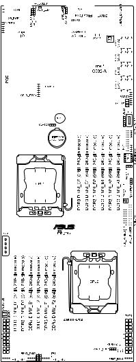
Z9NH-D12
|
|
|
|
|
|
|
|
|
|
|
|
|
|
|
|
|
|
|
|
|
|
|
|
|
|
|
|
|
|
|
|
|
|
|
|
|
|
|
|
|
|
|
|
|
|
|
|
|
|
|
|
|
|
|
|
|
|
|
|
|
|
|
|
|
|
|
|
|
|
|
|
|
|
|
|
|
|
|
|
|
|
|
|
|
|
|
|
|
|
|
|
|
|
|
|
|
|
|
|
|
|
|
|
|
|
|
|
|
|
|
|
|
|
|
|
|
|
|
|
|
|
|
|
|
|
|
|
|
|
|
|
|
|
|
|
|
|
|
|
|
|
|
|
|
|
|
|
|
|
|
|
|
|
|
|
|
|
|
|
|
|
|
|
|
|
|
|
|
|
|
|
|
|
|
|
|
|
|
|
|
|
|
|
|
|
|
|
|
|
|
|
|
|
|
|
|
|
|
|
|
|
|
|
|
|
|
|
|
|
|
|
|
|
|
|
|
|
|
|
|
|
|
|
|
|
|
|
|
|
|
|
|
|
|
|
|
|
|
|
|
|
|
|
|
|
|
|
|
|
|
|
|
|
|
|
|
|
|
|
|
|
|
|
|
|
|
|
|
|
|
|
|
|
|
|
|
|
|
|
|
|
|
|
|
|
|
|
|
|
|
|
|
|
|
|
|
|
|
|
|
|
|
|
|
|
|
|
|
|
|
|
|
|
|
|
|
|
|
|
|
|
|
|
|
|
|
|
|
|
|
|
|
|
|
|
|
|
|
|
|
|
|
|
|
|
|
|
|
|
|
|
|
|
|
|
|
|
|
|
|
|
|
|
|
|
|
|
|
|
|
|
|
|
|
|
|
|
|
|
|
|
|
|
|
|
|
|
|
|
|
|
|
|
|
|
|
|
|
|
|
|
|
|
|
|
|
|
|
|
|
|
|
|
|
|
|
|
|
|
|
|
|
|
|
|
|
|
|
|
|
|
|
|
|
|
|
|
|
|
|
|
|
|
|
|
|
|
|
|
|
|
|
|
|
|
|
|
|
|
|
|
|
|
|
|
|
|
|
|
|
|
|
|
|
|
|
|
|
|
|
|
|
|
|
|
|
|
|
|
|
|
|
|
|
|
|
|
|
|
|
|
|
|
|
|
|
|
|
|
|
|
|
|
|
|
|
|
|
|
|
|
|
|
|
|
|
|
|
|
|
|
|
|
|
|
|
|
|
|
|
|
|
|
|
|
|
|
|
|
|
|
|
|
|
|
|
|
|
|
|
|
|
|
|
|
|
|
|
|
|
|
|
|
|
|
|
|
|
|
|
|
|
|
|
|
|
|
|
|
|
|
|
|
|
|
|
|
|
|
|
|
|
|
|
|
|
|
|
|
|
|
|
|
|
|
|
|
|
|
|
|
|
|
|
|
|
|
|
|
|
|
|
|
|
|
|
|
|
|
|
|
|
|
|
|
|
|
|
|
|
|
|
|
|
|
|
|
|
|
|
|
|
|
|
|
|
|
|
|
|
|
|
|
|
|
|
|
|
|
|
|
|
|
|
|
|
|
|
|
|
|
|
|
|
|
|
|
|
|
|
|
|
|
|
|
|
|
|
|
|
|
|
|
|
|
|
|
|
|
|
|
|
|
|
|
|
|
|
|
|
|
|
|
|
|
|
|
|
|
|
|
|
|
|
|
|
|
|
|
|
|
|
|
|
|
|
|
|
|
|
|
|
|
|
|
|
|
|
|
|
|
|
|
|
|
|
|
|
|
|
|
|
|
|
|
|
|
|
|
|
|
|
|
|
|
|
|
|
|
|
|
|
|
|
|
|
|
|
|
|
|
|
|
|
|
|
|
|
|
|
|
|
|
|
|
|
|
|
|
|
|
|
|
|
|
|
|
|
|
|
|
|
|
|
|
|
|
|
|
|
|
|
|
|
|
|
|
|
|
|
|
|
|
|
|
|
|
|
|
|
|
|
|
|
|
|
|
|
|
|
|
|
|
|
|
|
|
|
|
|
|
|
|
|
|
|
|
|
|
|
|
|
|
|
|
|
|
|
|
|
|
|
|
|
|
|
|
|
|
|
|
|
|
|
|
|
|
|
|
|
|
|
|
|
|
|
|
|
|
|
|
|
|
|
|
|
|
|
|
|
|
|
|
|
|
|
|
|
|
|
|
|
|
|
|
|
|
|
|
|
|
|
|
|
|
|
|
|
|
|
|
|
|
|
|
|
|
|
|
|
|
|
|
|
|
|
|
|
|
|
|
|
|
|
|
|
|
|
|
|
|
|
|
|
|
|
|
|
|
|
|
|
|
|
|
|
|
|
|
|
|
|
|
|
|
|
|
|
|
|
|
|
|
|
|
|
|
|
|
|
|
|
|
|
|
|
|
|
|
|
|
|
|
|
|
|
|
|
|
|
|
|
|
|
|
|
|
|
|
|
|
|
|
|
|
|
|
|
|
|
|
|
|
|
|
|
|
|
|
|
|
|
|
|
|
|
|
|
|
|
|
|
|
|
|
|
|
|
|
|
|
|
|
|
|
|
|
|
|
|
|
|
|
|
|
|
|
|
|
|
|
|
|
|
|
|
|
|
|
|
|
|
|
|
|
|
|
|
|
|
|
|
|
|
|
|
|
|
|
|
|
|
|
|
|
|
|
|
|
|
|
|
|
|
|
|
|
|
|
|
|
|
|
|
|
|
|
|
|
|
|
|
|
|
|
|
|
|
|
|
|
|
|
|
|
|
|
|
|
|
|
|
|
|
|
|
|
|
|
|
|
|
|
|
|
|
|
|
|
|
|
|
|
|
|
|
|
|
|
|
|
|
|
|
|
|
|
|
|
|
|
|
|
|
|
|
|
|
|
|
|
|
|
|
|
|
|
|
|
|
|
|
|
|
|
|
|
|
|
|
|
|
|
|
|
|
|
|
|
|
|
|
|
|
|
|
|
|
|
|
|
|
|
|
|
|
|
|
|
|
|
|
|
|
|
|
|
|
|
|
|
|
|
|
|
|
|
|
|
|
|
|
|
|
|
|
|
|
|
|
|
|
|
|
|
|
|
|
|
|
|
|
|
|
|
|
|
|
|
|
|
|
|
|
|
|
|
|
|
|
|
|
|
|
|
|
|
|
|
|
|
|
|
|
|
|
|
|
|
|
|
|
|
|
|
|
|
|
|
|
|
|
|
|
|
|
|
|
|
|
|
|
|
|
|
|
|
|
|
|
|
|
|
|
|
|
|
|
|
|
|
|
|
|
|
|
|
|
|
|
|
|
|
|
|
|
|
|
|
|
|
|
|
|
|
|
|
|
|
|
|
|
|
|
|
|
|
|
|
|
|
|
|
|
|
|
|
|
|
|
|
|
|
|
|
|
|
|
|
|
|
|
|
|
|
|
|
|
|
|
|
|
|
|
|
|
|
|
|
|
|
|
|
|
|
|
|
|
|
|
|
|
|
|
|
|
|
|
|
|
|
|
|
|
|
|
|
|
|
|
|
|
|
|
|
|
|
|
|
|
|
|
|
|
|
|
|
|
|
|
|
|
|
|
|
|
|
|
|
|
|
|
|
|
|
|
|
|
|
|
|
|
|
|
|
|
|
|
|
|
|
|
|
|
|
|
|
|
|
|
|
|
|
|
|
|
|
|
|
|
|
|
|
|
|
|
|
|
|
|
|
|
|
|
|
|
|
|
|
|
|
|
|
|
|
|
|
|
|
|
|
|
|
|
|
|
|
|
|
|
|
|
|
|
|
|
|
|
|
|
|
|
|
|
|
|
|
|
|
|
|
|
|
|
|
|
|
|
|
|
|
|
|
|
|
|
|
|
|
|
|
|
|
|
|
|
|
|
|
|
|
|
|
|
|
|
|
|
|
|
|
|
|
|
|
|
|
|
|
|
|
|
|
|
|
|
|
|
|
|
|
|
|
|
|
|
|
|
|
|
|
|
|
|
|
|
|
|
|
|
|
|
|
|
|
|
|
|
|
|
|
|
|
|
|
|
|
|
|
|
|
|
|
|
|
|
|
|
|
|
|
|
|
|
|
|
|
|
|
|
|
|
|
|
|
|
|
|
|
|
|
|
|
|
|
|
|
|
|
|
|
|
|
|
|
|
|
|
|
|
|
|
|
|
|
|
|
|
|
|
|
|
|
|
|
|
|
2-6 |
|
|
|
|
|
|
|
|
|
|
|
|
|
|
|
|
|
|
|
|
|
|
|
|
|
|
|
|
|
|
|
|
|
|
|
|
|
|
|
|
|
|
Chapter 2: Hardware information |

2.2.4Layout contents
|
Slots/Sockets |
Page |
|
1. |
CPU sockets |
2-9 |
|
2. |
DDR3 sockets |
2-14 |
|
|
3. |
PCI Express x16 slot |
2-17 |
|
|
Onboard LEDs |
Page |
|
1. |
Baseboard Management Controller (BMC_LED1) |
2-20 |
||
2. |
CPU Warning LED (ERR_CPU1/2) |
2-20 |
||
|
3. |
Location LED (LOCLED1) |
2-21 |
|
|
|
4. |
Infiniband LED (LINK_LED/ACT_LED) |
2-21 |
|
|
Jumpers |
|
Page |
1. |
Clear RTC RAM (CLRTC1) |
2-22 |
||
2. |
VGA controller setting (3-pin VGA_SW1) |
2-23 |
||
3. |
LAN controller setting (3-pin LAN_SW1/ LAN_SW2) |
2-24 |
||
|
4. |
LSI MegaRAID or Intel RSTe selection jumper (3-pin RAID_SEL1) |
2-24 |
|
|
|
5. |
ME firmware force recovery setting (3-pin ME_RCVR1) |
2-25 |
|
|
6. |
DDR3 thermal event setting (3-pin DIMMTRIP1) |
2-25 |
|
|
7. |
PMBus1.2 PSU select jumper (3-pin SMART_PSU1) |
2-26 |
|
Rear panel connectors |
Page |
|
1. |
DM_LAN1 (RJ-45) port |
2-27 |
|
2. |
LAN 1 (RJ-45) port |
2-27 |
|
3. |
USB 2.0 ports 1 and 2 |
2-27 |
|
4. |
LAN 2 (RJ-45) port |
2-27 |
|
5. |
Video Graphics Adapter (VGA) port |
2-27 |
|
|
6. |
InfiniBand LED (Link/ACT) |
2-27 |
|
|
(Z9NH-D12/FDR and Z9NH-D12/10G only) |
|
|
7. |
InfiniBand (QSFP) |
2-27 |
|
|
(Z9NH-D12/FDR and Z9NH-D12/10G only) |
|
|
8. |
Location LED |
2-27 |
|
9. |
Serial (COM1) port |
2-27 |
ASUS Z9NH-D12 Series |
2-7 |

Internal connectors |
Page |
|
1. |
Serial ATA 6.0/3.0 Gb/s connectors |
2-29 |
|
(7-pin SATA6G 1–2 [Blue]; 7-pin SATA3G 3–4 [Black]) |
|
|
|
|
2. |
SATA connectors-ISAS connectors |
2-30 |
|
(7-pin ISAS1–4 [Gray]) |
|
|
|
|
3. |
Thermal sensor cable connectors (3-pin TR1, TR2) |
2-31 |
4. |
USB connectors (5-1 pin USB3;A-Type USB4) |
2-31 |
5. |
ASMB6 header (ASMB6) |
2-32 |
6. |
CPU, front and rear fan connectors |
2-33 |
|
(4-pin CPU_FAN1-2, FRNT_FAN1–4, REAR_FAN1-2) |
|
|
|
|
7. |
Serial General Purpose Input/Output connectors |
2-34 |
|
(8-1 pin ISGPIO1, SGPIO1) |
|
|
|
|
8. |
TPM connector (20-1-pin TPM1) |
2-35 |
9. |
Proprietary power connectors (20-pin PWR1/2; 4-pin PWR3) |
2-36 |
10. |
Power Supply SMBus (5-pin PSUSMB1) |
2-37 |
11. |
System panel connector (20-1 pin PANEL1 [White]) |
2-38 |
12. |
Auxiliary panel connector (20-2 pin AUX_PANEL1) |
2-39 |
2-8 |
Chapter 2: Hardware information |
 Loading...