

Page 1
E338
R
Xeon Installation Procedure
Central Processing Unit (CPU)
This motherboard provides two Single Edge Contact (SEC) Slot 2 connectors for
either one or two Intel® Xeon™ processors packaged in an SEC cartridge. When
only one processor is used, the other Slot 2 connector must be terminated with the
provided front side bus termination module.
NOTE: The pictures in the following pages will have the same item numbers
next to them for your reference. The following pictures are for reference only
and are not to size. The design and color of your items may be slightly different.
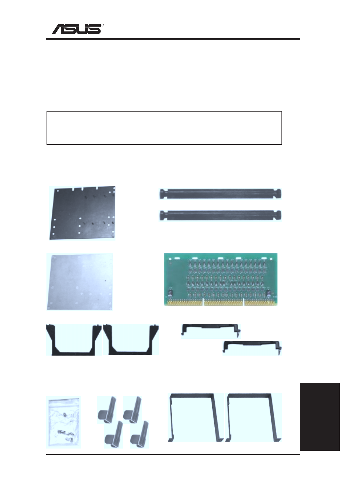
You should check to see that you have the following items with your motherboard:
(Item 1) Metal Baseboard x 1
(Item 2) Rubber Pad x 1
(Item 3) Retention Mechanism x 2
(Item 6) Retention Mechanism Brace Bar x 2
(Item 7) Front Side Bus Termination Module
(Item 8) Retention Mechanism Cap x 2
NOTE: For the retention mechanism and lock bar, there is a left and a right side. The left side has a single
dot and the right side has two dots (when holding the motherboard with the ATX connectors to the left).
(Item 4) Captive
Nut x 15 (in bag)
Lifter x 4
ASUS Xeon Installation
(Item 9) Retention Mechanism Support Frame x 2(Item 5) Cartridge
Guide 1
Xeon Processor
Installation Guide
Page 2
R
Xeon Installation Procedure
Xeon Processor Installation
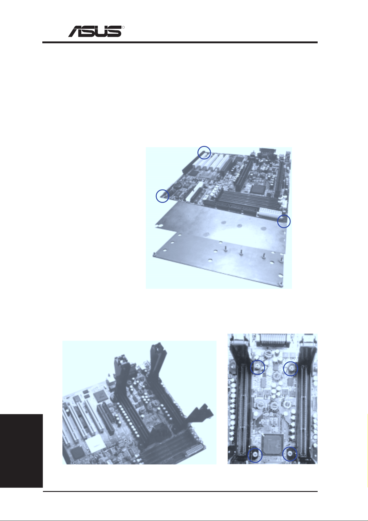
Step 1: Install the Baseboard
A metal baseboard is required to add stability to the motherboard. A rubber pad is
placed between the metal board and motherboard to provide insulation to prevent
shorting. Align the rubber pad over the metal baseboard so that the holes match.
Align the ASUS XG-DLS motherboard over the rubber pad and metal baseboard so
that the screws match up with the motherboard’s screw holes. Place and tighten
three captive nuts in the corner locations circled.
ASUS XG-DLS Motherboard
(Item 2) Rubber Pad
(Item 1) Metal Baseboard
Step 2: Install Retention Mechanisms
Place the retention mechanisms’ holes over the screws and the Slot2. Screw four
captive nuts onto the screws as circled in the picture on the right. Do not place the
other captive nuts yet.
(Item 3) Retention Mechanism
(Item 4) Captive Nut
Installation Guide
Xeon Processor
Two retention mechanisms installed
2
ASUS Xeon Installation
Guide
Four installed captive nuts
Page 3

R
Xeon Installation Procedure
Step 3: Install the Retention Mechanism Brace Bars
Place the retention mechanism brace bar into the groove on the top of the retention
mechanism as shown in the picture below. These pictures are views of the motherboard and retention mechanism with the ATX connectors away from yourself.
(Item 6) Retention Mechanism Brace Bar
Retention mechanism with
brace bar on top
One retention mechanism
with brace bar installed
Both retention mechanisms
with both brace bars installed
Step 4: Install Cartridge Lifters
Each Xeon processor requires two lifters in order to allow safe removal of the processor. The lifters clamps the cartridge on the two holes at each top corner.
(Item 5) CPU Lifter
One lifter being inserted over the
cartridge from a vertical position
Half-colapsed lifter after installation. The
lifter should freely rise and lower.
Step 5: Install a 2nd Processor or Termination Module
The motherboard supports a single or dual processor configuration. When a single
processor configuration is desired, a front side bus termination module is required
on the free slot 2 connector.
(Item 7) Front Side Bus Termination Module
Single processor configuration with terminator.
ASUS Xeon Installation
Dual processor configuration.
Guide 3
Xeon Processor
Installation Guide
Page 4

R
Xeon Installation Procedure
Step 6: Install Retention Mechanism Cap
The retention mechanism has a cap to keep the processor down while preventing the
retention mechanism’s walls from spreading.
(Item 8) Retention
Mechanism Lock Bar
The cap must go in from the left side first
(toward the ATX connectors). The left side
has one dot, while the right side has two dots.
The right end of the cap enters the retention
mechanism and a click is heard as it snaps in
place.
Step 7: Install Retention Mechanism Frame
In order to keep the retention mechanism lock bar from coming free and to add extra
stability to the plastic retention mechanisms, a metal frame is used accross both retention mechanisms. After installing the frame, four captive nuts should be tightened on
the feet of the frame to the screws protruding from the retention mechanisms. This is
the end of the Xeon™ processor installation and you should have 4 extra (only 11 is
used out of 15) captive nuts in case you loose any.
(Item 9) Retention Mechanism Support Frame
Retention mechansim fram around single
processor configuration with terminator.
Removing the Xeon™ Processor
If you want to remove the processor, first remove the retention mechanism frame,
then remove the cap. The processor is pulled out of the slot 2 connector by flipping
both lifters at the same time so that the processor raises out of the connector . When
both lifters are vertical, pull out the processor by holding the lifters.
Installation Guide
Xeon Processor
4
Retention mechansim fram around
dual processor configuration.
The processor raised out of the slot
2 connector by the reverse force of
the lifters as they are pryed to a
vertical position.
ASUS Xeon Installation
Guide
 Loading...