


Asus X99-DELUXE User Manual

X99-DELUXE
Series
Motherboard

E9504
First Edition
August 2014
Copyright© 2014 ASUSTeK COMPUTER INC. All Rights Reserved.
No part of this manual, including the products and software described in it, may be reproduced,
transmitted, transcribed, stored in a retrieval system, or translated into any language in any form or by any
means, except documentation kept by the purchaser for backup purposes, without the express written
permission of ASUSTeK COMPUTER INC. (“ASUS”).
Product warranty or service will not be extended if: (1) the product is repaired, modied or altered, unless
such repair, modication of alteration is authorized in writing by ASUS; or (2) the serial number of the
product is defaced or missing.
ASUS PROVIDES THIS MANUAL “AS IS” WITHOUT WARRANTY OF ANY KIND, EITHER EXPRESS
OR IMPLIED, INCLUDING BUT NOT LIMITED TO THE IMPLIED WARRANTIES OR CONDITIONS OF
MERCHANTABILITY OR FITNESS FOR A PARTICULAR PURPOSE. IN NO EVENT SHALL ASUS, ITS
DIRECTORS, OFFICERS, EMPLOYEES OR AGENTS BE LIABLE FOR ANY INDIRECT, SPECIAL,
INCIDENTAL, OR CONSEQUENTIAL DAMAGES (INCLUDING DAMAGES FOR LOSS OF PROFITS,
LOSS OF BUSINESS, LOSS OF USE OR DATA, INTERRUPTION OF BUSINESS AND THE LIKE),
EVEN IF ASUS HAS BEEN ADVISED OF THE POSSIBILITY OF SUCH DAMAGES ARISING FROM ANY
DEFECT OR ERROR IN THIS MANUAL OR PRODUCT.
SPECIFICATIONS AND INFORMATION CONTAINED IN THIS MANUAL ARE FURNISHED FOR
INFORMATIONAL USE ONLY, AND ARE SUBJECT TO CHANGE AT ANY TIME WITHOUT NOTICE,
AND SHOULD NOT BE CONSTRUED AS A COMMITMENT BY ASUS. ASUS ASSUMES NO
RESPONSIBILITY OR LIABILITY FOR ANY ERRORS OR INACCURACIES THAT MAY APPEAR IN THIS
MANUAL, INCLUDING THE PRODUCTS AND SOFTWARE DESCRIBED IN IT.
Products and corporate names appearing in this manual may or may not be registered trademarks or
copyrights of their respective companies, and are used only for identication or explanation and to the
owners’ benet, without intent to infringe.
Offer to Provide Source Code of Certain Software
This product contains copyrighted software that is licensed under the General Public License (“GPL”),
under the Lesser General Public License Version (“LGPL”) and/or other Free Open Source Software
Licenses. Such software in this product is distributed without any warranty to the extent permitted by the
applicable law. Copies of these licenses are included in this product.
Where the applicable license entitles you to the source code of such software and/or other additional data,
you may obtain it for a period of three years after our last shipment of the product, either
(1) for free by downloading it from http://support.asus.com/download
or
(2) for the cost of reproduction and shipment, which is dependent on the preferred carrier and the location
where you want to have it shipped to, by sending a request to:
ASUSTeK Computer Inc.
Legal Compliance Dept.
15 Li Te Rd.,
Beitou, Taipei 112
Taiwan
In your request please provide the name, model number and version, as stated in the About Box of the
product for which you wish to obtain the corresponding source code and your contact details so that we
can coordinate the terms and cost of shipment with you.
The source code will be distributed WITHOUT ANY WARRANTY and licensed under the same license as
the corresponding binary/object code.
This offer is valid to anyone in receipt of this information.
ASUSTeK is eager to duly provide complete source code as required under various Free Open Source
Software licenses. If however you encounter any problems in obtaining the full corresponding source
code we would be much obliged if you give us a notication to the email address gpl@asus.com, stating
the product and describing the problem (please DO NOT send large attachments such as source code
archives, etc. to this email address).
ii

Contents
Safety information ....................................................................................................... v
About this guide ......................................................................................................... vi
X99-DELUXE specifications summary ................................................................... viii
Package contents ..................................................................................................... xiv
Installation tools and components .......................................................................... xv
Chapter 1: Product Introduction
1.1 Special features..........................................................................................1-1
1.1.1 Product highlights........................................................................1-1
1.1.2 Other special features .................................................................1-2
1.2 Motherboard overview ............................................................................... 1-3
1.2.1 Before you proceed .....................................................................1-3
1.2.2 Motherboard layout .....................................................................1-4
1.2.3 Central Processing Unit (CPU) ...................................................1-6
1.2.4 System memory ..........................................................................1-7
1.2.5 Expansion slots .........................................................................1-12
1.2.6 Onboard buttons and switches..................................................1-15
1.2.7 Jumpers .................................................................................... 1-20
1.2.8 Onboard LEDs ..........................................................................1-21
1.2.9 Internal connectors....................................................................1-27
Chapter 2: Basic installation
2.1 Building your PC system ...........................................................................2-1
2.1.1 Motherboard installation ..............................................................2-1
2.1.2 CPU installation...........................................................................2-3
2.1.3 CPU heatsink and fan assembly installation ............................... 2-5
2.1.4 DIMM installation.........................................................................2-6
2.1.5 ATX Power connection................................................................2-7
2.1.6 SATA device connection .............................................................2-8
2.1.7 Front I/O Connector ....................................................................2-9
2.1.8 Expansion Card installation.......................................................2-10
2.1.9 Wi-Fi antenna installation ..........................................................2-13
2.2 BIOS update utility ................................................................................... 2-14
2.3 Motherboard rear and audio connections ............................................. 2-15
2.3.1 Rear I/O connection ..................................................................2-15
2.3.2 Audio I/O connections ...............................................................2-17
2.4 Starting up for the first time .................................................................... 2-19
2.5 Turning off the computer ........................................................................2-20
iii

Chapter 3: BIOS setup
3.1 Knowing BIOS ............................................................................................ 3-1
3.2 BIOS setup program .................................................................................. 3-2
3.2.1 EZ Mode......................................................................................3-3
3.2.2 Advanced Mode ..........................................................................3-4
3.2.3 QFan Control...............................................................................3-7
3.2.4 EZ Tuning Wizard .......................................................................3-9
3.3 My Favorites ............................................................................................. 3-11
3.4 Main menu ................................................................................................3-13
3.5 Ai Tweaker menu ......................................................................................3-15
3.6 Advanced menu .......................................................................................3-32
3.6.1 CPU Conguration ....................................................................3-33
3.6.2 PCH Conguration ....................................................................3-35
3.6.3 PCH Storage Conguration.......................................................3-36
3.6.4 System Agent Conguration .....................................................3-38
3.6.5 USB Conguration ....................................................................3-39
3.6.6 Platform Misc Conguration ......................................................3-41
3.6.7 Onboard Devices Conguration ................................................3-42
3.6.8 APM Conguration ....................................................................3-45
3.6.8 Network Stack Conguration.....................................................3-45
3.7 Monitor menu ...........................................................................................3-47
3.8 Boot menu ................................................................................................3-51
3.9 Tool menu ................................................................................................. 3-57
3.9.1 ASUS EZ Flash 2 Utility ............................................................3-57
3.9.2 ASUS O.C. Prole .....................................................................3-58
3.9.3 ASUS DRAM SPD Information .................................................3-59
3.10 Exit menu .................................................................................................. 3-60
3.11 Updating BIOS .......................................................................................... 3-61
3.11.1 EZ Update .................................................................................3-61
3.11.2 ASUS EZ Flash 2 ......................................................................3-61
3.11.3 ASUS CrashFree BIOS 3 ..........................................................3-63
Appendices
Notices .................................................................................................................... A-1
ASUS contact information ...................................................................................... A-5
iv

Safety information
Electrical safety
• To prevent electrical shock hazard, disconnect the power cable from the electrical outlet
before relocating the system.
• When adding or removing devices to or from the system, ensure that the power cables
for the devices are unplugged before the signal cables are connected. If possible,
disconnect all power cables from the existing system before you add a device.
• Before connecting or removing signal cables from the motherboard, ensure that all
power cables are unplugged.
• Seek professional assistance before using an adapter or extension cord. These devices
could interrupt the grounding circuit.
• Ensure that your power supply is set to the correct voltage in your area. If you are not
sure about the voltage of the electrical outlet you are using, contact your local power
company.
• If the power supply is broken, do not try to x it by yourself. Contact a qualied service
technician or your retailer.
Operation safety
• Before installing the motherboard and adding devices on it, carefully read all the manuals
that came with the package.
• Before using the product, ensure all cables are correctly connected and the power
cables are not damaged. If you detect any damage, contact your dealer immediately.
• To avoid short circuits, keep paper clips, screws, and staples away from connectors,
slots, sockets and circuitry.
• Avoid dust, humidity, and temperature extremes. Do not place the product in any area
where it may become wet.
• Place the product on a stable surface.
• If you encounter technical problems with the product, contact a qualied service
technician or your retailer.
v

About this guide
This user guide contains the information you need when installing and conguring the
motherboard.
How this guide is organized
This guide contains the following parts:
1. Chapter 1: Product introduction
This chapter describes the features of the motherboard and the new technology it
supports. It includes description of the switches, jumpers, and connectors on the
motherboard.
2. Chapter 2: Basic installation
This chapter lists the hardware setup procedures that you have to perform when
installing system components.
3. Chapter 3: BIOS setup
This chapter tells how to change system settings through the BIOS Setup menus.
Detailed descriptions of the BIOS parameters are also provided.
Where to find more information
Refer to the following sources for additional information and for product and software
updates.
1. ASUS website
The ASUS website (www.asus.com) provides updated information on ASUS hardware
and software products.
2. Optional documentation
Your product package may include optional documentation, such as warranty yers,
that may have been added by your dealer. These documents are not part of the
standard package.
vi

Conventions used in this guide
To ensure that you perform certain tasks properly, take note of the following symbols used
throughout this manual.
DANGER/WARNING: Information to prevent injury to yourself when trying to
complete a task.
CAUTION: Information to prevent damage to the components when trying to
complete a task
IMPORTANT: Instructions that you MUST follow to complete a task.
NOTE: Tips and additional information to help you complete a task.
Typography
Bold text
Italics
<Key> Keys enclosed in the less-than and greater-than sign
<Key1> + <Key2> + <Key3> If you must press two or more keys simultaneously, the key
Indicates a menu or an item to select.
Used to emphasize a word or a phrase.
means that you must press the enclosed key.
Example: <Enter> means that you must press the Enter or
Return key.
names are linked with a plus sign (+).
vii

X99-DELUXE specifications summary
LGA2011-v3 socket for Intel® Core™ i7 processors
CPU
Chipset
Memory
Expansion slots
Multi-GPU support
Storage
Supports 22nm CPU, up to 20 MB Smart Cache*
Supports Intel® Turbo Boost Technology 2.0*
* The support of these features depends on the CPU types.
Intel® X99 Express Chipset
8 x DIMM, max. 64 GB, DDR4 2800 (O.C.)* / 2666 (O.C.)* / 2400
(O.C.)* / 2133 MHz, non-ECC, un-buffered memory
Quad channel memory architecture
Supports Intel® Extreme Memory Prole (XMP)
* Hyper DIMM support is subject to the physical characteristics of individual
CPUs. Please refer to Memory QVL (Qualified Vendors List) for details.
40-LANE CPU
5 x PCI Express 3.0/2.0 x16 slots* (single at x16, dual at x16/x16,
triple at x16/x16/x8, quad at x8/x8/x16/x8, or quintuple at x8/x8/x8/x8/
x8 mode)
1 x PCI Express 2.0 x4 slot** (compatible with PCIe x1 and x4 devices)
28-LANE CPU
3 x PCI Express 3.0/2.0 x16 slots (single at x16, dual at x16/x8, triple at
x8/x8/x8 mode)
2 x PCI Express 2.0 x16 slot (max. at x1 mode, compatible with PCIe
x1 devices)
1 x PCI Express 2.0 x4 slot** (compatible with PCIe x1 and x4 devices)
* The PCIe x16_5 shares bandwidth with M.2 x4.
** The PCIe x4_1, USB3_E12 and SATAEXPRESS_E1 connectors share the
same bandwidth. By default, the USB3_E12 and SATAEXPRESS_E1 will
automatically run at x2 mode with PCIe x4_1 disabled when no device is
installed on PCIe x4_1. Remember to adjust the bandwidth option in BIOS if
you install any PCIe device on the PCIe x4_1 slot.
Supports NVIDIA® 3-Way/Quad-GPU SLI™ Technology (with 2 PCIe
x16 graphics card)
Supports AMD® 3-Way/Quad-GPU CrossFireX™ Technology
Intel® X99 Express Chipset with RAID 0, 1, 5, 10 and Intel
Rapid Storage Technology 13 support
- 1 x SATA Express port (gray at upper, compatible with 2 x SATA 6
Gb/s ports)
- 1 x M.2 socket 3 with vertical M Key design, type 2242/2260/2280
storage devices support (PCIE mode only)
- 8 x SATA 6.0 Gb/s ports* (4 x gray from controller 1, 4 x black from
controller 2)
- Supports Intel® Rapid Storage Technology** (Intel® Smart Response
Technology, Rapid Recover Technology)
(continued on the next page)
®
viii

X99-DELUXE specifications summary
ASMedia® SATA Express controller***
- 1 x SATA Express ports (gray at bottom, compatible with 2 x
SATA 6 Gb/s ports)
Storage
LAN
Wireless Data Network
Bluetooth
Audio
USB
* Due to chipset behavior, the SATA6G_78 and SATA6G_910 ports
(black) do not support Intel® Rapid Storage Technology including RAID
configuration.
** These functions work depending on the CPU installed.
*** These SATA ports are for data hard drives only. ATAPI devices are
not supported.
Gigabit LAN controllers—802.3az Energy Efcient Ethernet (EEE)
appliance
- Intel® I218-V Gigabit LAN - Dual interconnect between the
integrated Media Access Controller (MAC) and physical layer
(PHY)
- Intel® I211-AT Gigabit LAN controller
- ASUS Turbo LAN utility
Speedy Wi-Fi 802.11 a/b/g/n/ac supports dual frequency band 2.4/5
GHz up to 1300 Mbit/s transfer speed
ASUS Wi-Fi GO! Utility
Bluetooth v4.0
Realtek® ALC1150 8-channel high denition audio CODEC
featuring Crystal Sound 2
- Separate layer for left and right track, ensuring both sounds
deliver equal quality
- Top notch audio sensation delivers according to the audio
conguration
- Audio shielding ensures precision analog/digital separation
and greatly reduced multi-lateral interference
- Audio Amplier to enhance the highest quality sound for
headphone and speakers
- Premium Japan-made audio capacitors provide warm, natural,
and immersive sound with exceptional clarity and delity
- High quality 112 dB SNR stereo playback output (Line-out at
rear) and 104 dB SNR recording (Line-in) support
- Absolute pitch 192 KHz/24-bit True BD Lossless Sound
- BD audio layer content protection
- DTS UltraPC II
- DTS Connect
- Supports jack-detection, multi-streaming and front panel jackretasking (MIC)
- Optical S/PDIF out ports at rear I/O
Intel® X99 Express Chipset - supports ASUS USB 3.0
Boost
- 4 x USB 3.0/2.0 ports at mid-board for front panel support
- 6 x USB 2.0/1.1 ports (4 ports at mid-board, 4 ports at rear
panel)
(continued on the next page)
ix

X99-DELUXE specifications summary
ASMedia® USB 3.0 controller - support ASUS USB 3.0
Boost
USB
ASUS Exclusive
Features
ASUS Exclusive
Features
- 2 x USB 3.0/2.0 ports at rear panel (blue)
ASMedia® USB 3.0 Hubs - support ASUS USB 3.0 Boost
- 8 x USB 3.0/2.0 ports at rear panel (blue)
Flagship Performance
5-Way Optimization by Dual Intelligent Processors 5
- Whole system optimization with a single click! 5-Way
Optimization tuning key perfectly consolidates TPU, EPU,
DIGI+ Power Control, Fan Xpert 3, and Turbo APP together,
providing better CPU performance, efcient power saving,
precise digital power control, whole system cooling and even
tailor your own app usages.
DIGI+ Power Control
CPU Power
- Industry leading digital 8-phase power design
- ASUS CPU power utility
DRAM Power
- Industry leading digital 4-phase DRAM power design
- ASUS DRAM power utility
TPU
- Auto Tuning, TPU, GPU Boost, 2-level TPU switch
EPU
- EPU, EPU switch
ASUS Fan Xpert3
- Featuring Fan Auto Tuning function and multiple thermistors
selection for optimized system cooling control.
Turbo App
- Featuring automatic system performance tuning, network
priority, and audio scene conguration for selected
applications.
UEFI BIOS
- Most advanced options with fast response time
M.2 and SATA Express onboard
- The latest transfer technology with up to 32 Gb/s data transfer
speeds for M.2
- The ultra-fast transfer technology with up to 10 Gb/s data
transfer speeds for SATA Express
Special Memory O.C. Design
- Superb memory O.C. capability under full load by minimizing
the coupling noise and signal reection effect
Thunderbolt Ready (Optional)
- Blistering-fast 20 Gb/s data transfer upgrades with
ThunderboltEX II series
(continued on the next page)
x

X99-DELUXE specifications summary
Powerful Home Server
ASUS HomeCloud Server
Wi-Fi GO!
- Wi-Fi GO! function: Cloud GO!, Remote Desktop, Remote
Keyboard & Mouse, File Transfer
- Wi-Fi GO! & NFC Remote app for portable smartphone/tablet,
supporting iOS7 and Android 4.0 systems
Media Streamer
- Pipe music or movies from your PC to a smart TV
- Media Streamer app for portable smartphone/tablet,
supporting iOS7 and Android 4.0 systems
NFC Express 2 support (Optional)
- NFC receiver and 2-port USB 3.0 hub
- NFC one-touch features: Video-to-go, Photo Express, Remote
Desktop, Quick Launch, Windows® 8 Login and Bluetooth
pairing
Gamers and Professionals
Turbo APP
- Perform each application with tailored performance, network
priority, and audio conguration for your needs
Turbo LAN
ASUS Exclusive
Features
- Experience smooth online gaming with lower pings and less
lags
Crystal Sound 2
- Feel the sound power with different usage scenarios
Steam support
- Compatible with the most fun gaming platform under
Windows® system
ASUS EZ DIY
Push Notice
- Monitor your PC status with smart devices in real time
USB BIOS Flashback
- with USB BIOS Flashback Wizard for EZ BIOS download
scheduling
UEFI BIOS
- featuring friendly graphics user interface
- ASUS O.C. Tuner
- ASUS CrashFreeBIOS 3
- ASUS EZ Flash 2
Q-Design
- ASUS Q-Code
- ASUS Q-Shield
- ASUS Q-LED (CPU, DRAM, VGA, Boot Device LED)
- ASUS Q-Slot
(continued on the next page)
xi

X99-DELUXE specifications summary
ASUS Exclusive
Features
ASUS Special Features
ASUS Quiet Thermal
Solution
ASUS Exclusive
Overclocking Features
Rear Panel I/O Ports
- ASUS Q-DIMM
- ASUS Q-Connector
ASUS 5X Protection:
- ASUS DIGI+VRM - 8 phase digital power design
- ASUS Enhanced DRAM Overcurrent Protection - Short circuit
damage prevention
- ASUS ESD Guards - Enhanced ESD protection
- ASUS High-Quality 5K-Hour Solid Capacitors - 2.5x long
lifespan with excellent durability
- ASUS Stainless Steel Back I/O - 3x more durable corrosionresistant coating
USB 3.0 Boost
USB Charger+
Ai Charger+
Disk Unlocker
AI Suite 3
MemOK!
EZ XMP
Quiet Thermal Design
- ASUS Fan Xpert 3
- ASUS Fanless Design: Heat-pipe solution with an aesthetic
streamline IO cover
Precision Tweaker 2
- vCore: Adjustable CPU Core voltage at 0.001 V increment
- iGPU: Adjustable CPU Graphics voltage at 0.001 V increment
- vCCIO: Adjustable Analog and Digital I/O voltage at 0.001 V
increment
- vCCIN: Adjustable CPU Input voltage at 0.01 V increment
- vCCSA: Adjustable CPU System Agent voltage at 0.001 V
increment
- vDRAM Bus: 110-step Memory voltage control
- vPCH: 176-step Chipset voltage control
SFS (Stepless Frequency Selection)
- BCLK/PCIE frequency tuning from 80 MHz to 300 MHz at 0.1
MHz increment.
Overclocking Protection
- ASUS C.P.R. (CPU Parameter Recall)
1 x BIOS Flashback button
1 x ASUS Wi-Fi GO! module (Wi-Fi 802.11 a/b/g/n/ac and Bluetooth
v 4.0)
1 x Optical S/PDIF Out port
2 x LAN (RJ45) ports (2 x Intel® LAN)
10 x USB 3.0/2.0 ports (blue)
2 x USB 2.0/1.1 ports (bottom port supports USB BIOS Flashback)
8-channel Audio I/O ports
(continued on the next page)
xii

X99-DELUXE specifications summary
2 x 19-pin USB 3.0/2.0 connectors support additional 4 USB ports
2 x USB 2.0/1.1 connectors support additional 4 USB ports
1 x M.2 Socket 3 with vertical M Key design, type 2242/2260/2280
storage devices support (PCIe mode only)
2 x SATA Express connectors (gray)
8 x SATA 6 Gb/s connectors (4 x gray, 4 x black)
1 x 4-pin CPU Fan connector for both 3-pin (DC mode) and 4-pin
(PWM mode) CPU coolers control with auto-detection support
1 x 4-pin CPU Optional Fan connector (CPU_OPT)
4 x 4-pin Chassis Fan connectors for 3-pin (DC mode) and 4-pin
(PWM mode) coolers control
1 x Front panel audio connector (AAFP)
1 x S/PDIF out header
Internal I/O connectors
BIOS features
Manageability
Support DVD contents
Operating system support
Form factor
1 x 5-pin Thunderbolt header for ThunderboltEX II series support
1 x TPM connector
1 x 24-pin EATX Power connector
1 x 8-pin EATX 12V Power connector
1 x System Panel (Q-Connector)
1 x 5-pin EXT_FAN (Extension Fan) connector
1 x 3-pin CHASSIS (Chassis intrusion) connector
1 x MemOK! button
1 x Clear CMOS button
1 x EPU switch
1 x TPU switch (with advanced two-stage adjustments)
1 x EZ XMP switch
1 x SLI/CFX switch (2/3-Way adjustments)
1 x Power-on switch
1 x Reset switch
128 Mb Flash ROM, UEFI AMI BIOS, PnP, DMI 2.7, WfM 2.0,
SM BIOS 2.7, ACPI 5.0, Multi-language BIOS, ASUS EZ Flash
2, CrashFree BIOS 3, F11 EZ Tuning Wizard, F6 Qfan Control,
F3 My Favorites, Quick Note, Last Modied Log, F12 PrintScreen
function, F3 Shortcut function, and ASUS DRAM SPD (Serial
Presence Detect) memory information
WfM 2.0, DMI 2.7, WOL by PME, PXE
Drivers
ASUS Utilities
EZ Update
Anti-virus software (OEM version)
Windows® 8.1 / Windows® 8 / Windows® 7
ATX form factor: 12 in. x 9.6 in. (30.5 cm x 24.4 cm)
Specications are subject to change without notice.
xiii
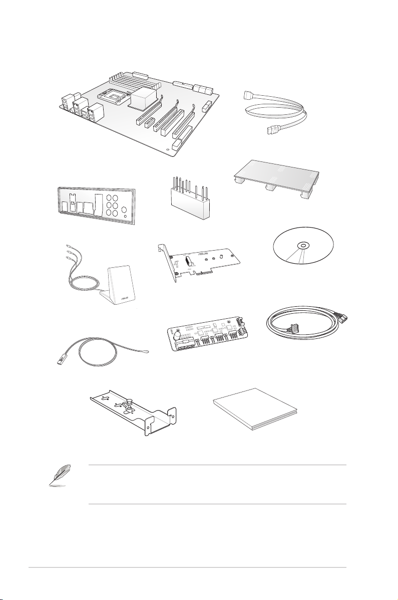
Package contents
Check your motherboard package for the following items
8 x Serial ATA 6 Gb/s cables
ASUS X99-DELUXE motherboard
1 x 2-WAY/3-WAY SLI card
1 x ASUS Q-Shield
1 x 3T3R dual-band Wi-Fi moving antennas
(Wi-Fi 802.11a/b/g/n/ac compliant)
1 x Thermistor cable
M.2 Racket
1 x 2-in-1 ASUS Q-Connector kit
• If any of the above items is damaged or missing, contact your retailer.
• The illustrated items above are for reference only. Actual product specications may
vary with different models.
HYPER M.2 x 4 (optional)
FAN EXTENSION CARD
(optional)
5-pin Fan extension cable
User Manual
User Guide
Support DVD
(optional)
xiv
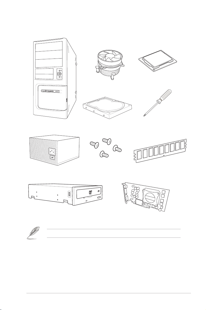
Installation tools and components
Intel® LGA2011-v3 compatible CPU Fan
Intel® LGA2011-v3 CPU
PC chassis
Power supply unit
SATA optical disc drive (optional)
SATA hard disk drive
1 bag of screws
Philips (cross) screwdriver
DIMM
Graphics card
The tools and components in the table above are not included in the motherboard package.
xv

xvi

Chapter 1: Product Introduction
Product introduction
1
1.1 Special features
1.1.1 Product highlights
LGA2011-v3 socket for Intel® Core™ i7 processors
This motherboard supports Intel® Core™ i7 processors in the LGA2011-v3 package. It
provides great graphics and system performance with its GPU, quad-channel DDR4 memory
slots and PCI Express 2.0/3.0 expansion slots.
Intel® X99 Express Chipset
Intel® X99 Express Chipset is a single chipset that supports the LGA2011-v3 socket for Intel
Core™ i7 processors. It utilizes the serial point-to-point links, which increases bandwidth
and enhances the system’s performance. It natively supports up to eight (8) USB 3.0 ports,
fourteen (14) SATA 6 Gb/s ports, and M.2 support for faster data retrieval. It also enables the
iGPU function for Intel® integrated graphics performance.
PCI Express® 3.0
PCI Express® 3.0 (PCIe 3.0) is the PCI Express bus standard that provides twice the
performance and speed of PCIe 2.0. It provides an optimal graphics performance,
unprecedented data speed and seamless transition with its complete backward compatibility
to PCIe 1.0/2.0 devices.
3-WAY/Quad-GPU SLI and 3-WAY CrossFireX™ Support
This motherboad features NVIDIA 3-WAY/Quad SLI and 3-Way AMD CrossreX support that
enables mulit-GPU setup, giving you the full power of the latest graphics technologies. It also
features native support for 4K/UHD (ultra high denition) resolution of up to 4096 x 2160 via
HDMI or DisplayPort, resulting to four times the number of pixels for incredible visual clarity,
detail, and realism.
SATA Express support
SATA Express provides faster data transfer speeds of up to 10 Gb/s, allowing your system to
catch up with the speed of the SSDs. It also features backward compatibility with up to two
SATA drives of the same speed.
®
ASUS X99-DELUXE Series
Chapter 1
1-1

Quad-Channel DDR4 2800 MHz Support
The motherboard supports the quad-channel DDR4 memory that features data transfer rates
of DDR4 2800 MHz to boost the system’s performance, and to meet the higher bandwidth
requirements of 3D graphics, multimedia and Internet applications.
Dual PCIe 3.0 x4 M.2 Support
With a 4x PCI Express 3.0/2.0 bandwidth, the M.2 can support up to 32 Gbit/s of data tranfer
speed. It is a perfect choice for the operating system or application drive, making your system
and its installed apps work in a faster pace.
Complete USB 3.0 integration
This motherboard offers you the strategic USB 3.0 accessibility for both the front and rear
panels, allowing you to experience the convenience of the latest plug and play connectivity
solution at speed up to ten times faster than USB 2.0.
1.1.2 Other special features
DTS Connect
To get the most out of your audio entertainment across all formats and quality levels, DTS
Connect combines two enabling technologies, DTS Neo:PC™ upmixes stereo sources (CDs,
MP3s, WMAs, internet radio) into as many as 7.1 channels of incredible surround sound.
Consumers can connect their PC to a home theater system. DTS Interactive is capable of
performing mult-channel encoding of DTS bitstreams on personal computers, and sending
encoded bitstreams out of a digital audio connection (such as S/PDIF or HDMI) designed to
deliver audio to an external decoder.
DTS UltraPC II
DTS UltraPC II delivers a superior surround sound experience through your system’s
speakers and headphones while monitoring and balancing the loudness level difference
between digital audio formats. It also ehnances the audio settings through augmenting
low and high frequencies of musical tones, restores compressed or re-mastered sounds,
improves bass performance even without a subwoofer, and improves dialogues derived from
DVD or Blu-ray Disc™.
ErP Ready
The motherboard is European Union’s Energy-related Products (ErP) ready, and ErP
requires products to meet certain energy efciency requirement in regards to energy
consumptions. This is in line with ASUS vision of creating environment-friendly and energy-
efcient products through product design and innovation to reduce carbon footprint of the
product and thus mitigate environmental impacts.
Chapter 1
1-2
Chapter 1: Product introduction

1.2 Motherboard overview
1.2.1 Before you proceed
Take note of the following precautions before you install motherboard components or change
any motherboard settings.
• Unplug the power cord from the wall socket before touching any component.
• Before handling components, use a grounded wrist strap or touch a safely grounded
object or a metal object, such as the power supply case, to avoid damaging them due
to static electricity.
• Hold components by the edges to avoid touching the ICs on them.
• Whenever you uninstall any component, place it on a grounded antistatic pad or in the
bag that came with the component.
• Before you install or remove any component, ensure that the ATX power supply is
switched off or the power cord is detached from the power supply. Failure to do so
may cause severe damage to the motherboard, peripherals, or components.
ASUS X99-DELUXE Series
Chapter 1
1-3
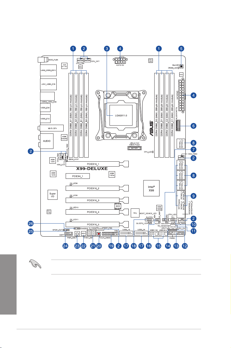
1.2.2 Motherboard layout
Chapter 1
1-4
Refer to 1.2.9 Internal connectors and 2.3.1 Rear I/O connection for more information
about rear panel connectors and internal connectors.
Chapter 1: Product introduction

Layout contents
Connectors/Jumpers/Buttons and switches/Slots Page
1. DDR4 DIMM slots 1-7
2. CPU, CPU optional, extension, and chassis fan connectors
(4-pin CPU_FAN, 4-pin CPU_OPT, 5-pin EXT_FAN, 4-pin CHA_FAN1-4 )
3. LGA2011-v3 CPU socket 1-6
4. ATX power connectors (24-pin EATXPWR, 8-pin EATX12V) 1-33
5. MemOK! button 1-16
6. M.2 Socket 3 1-36
7. EPU switch 1-18
8. Intel® Serial ATA 6 Gb/s connectors (7-pin SATA6G_12, SATA 6G_34,
SATA 6G_56/SATAEXPRESS_1, SATA 6G_78, SATA6G_910)
9. ASMedia® Serial ATA 6 Gb/s connectors (7-pin SATA6G_E12/
SATAEXPRESS_E1)
10. TPU switch 1-17
11. Thunderbolt header (5-pin TB_HEADER) 1-36
12. CPU Over Voltage jumper (3-pin CPU_OV) 1-20
13. System panel connector (20-8 pin PANEL) 1-34
14. DirectKey connector (2-pin DRCT) 1-35
15. USB 2.0 connectors (10-1 pin USB1112; USB1314) 1-31
16. EZ XMP switch 1-20
17. USB 3.0 connectors (20-1 pin USB3_12, USB3_34) 1-30
18. SLI/CFX switch 1-19
19. TPM connector (20-1 pin TPM) 1-35
20. Clear CMOS button (CLR_CMOS) 1-19
21. Q-Code LEDs 1-23
22. Reset button 1-15
23. Power-on button 1-15
24. Front panel audio connector (10-1 pin AAFP) 1-29
25. Digital audio connector (4-1 pin SPDIF_OUT) 1-29
26. Chassis intrusion connector (4-1 pin CHASSIS) 1-37
1-32
1-28
1-27
ASUS X99-DELUXE Series
Chapter 1
1-5
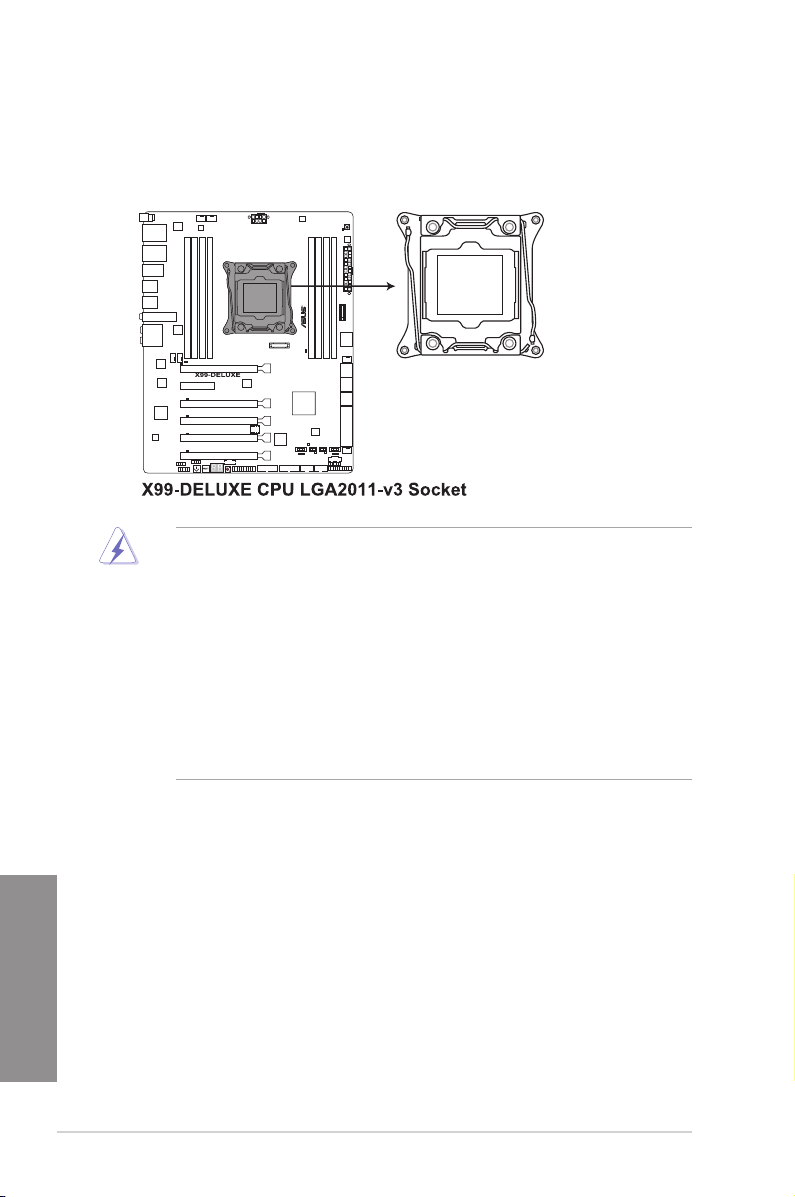
1.2.3 Central Processing Unit (CPU)
The motherboard comes with a surface mount LGA2011-v3 socket designed for Intel
i7 processors.
• Ensure that all power cables are unplugged before installing the CPU.
• Upon purchase of the motherboard, ensure that the PnP cap is on the socket and
the socket contacts are not bent. Contact your retailer immediately if the PnP cap
is missing, or if you see any damage to the PnP cap/socket contacts/motherboard
components. ASUS will shoulder the cost of repair only if the damage is shipment/
transit-related.
• Keep the cap after installing the motherboard. ASUS will process Return Merchandise
Authorization (RMA) requests only if the motherboard comes with the cap on the
LGA2011-v3 socket.
• The product warranty does not cover damage to the socket contacts resulting from
incorrect CPU installation/removal, or misplacement/loss/incorrect removal of the PnP
cap.
®
Core™
Chapter 1
1-6
Chapter 1: Product introduction
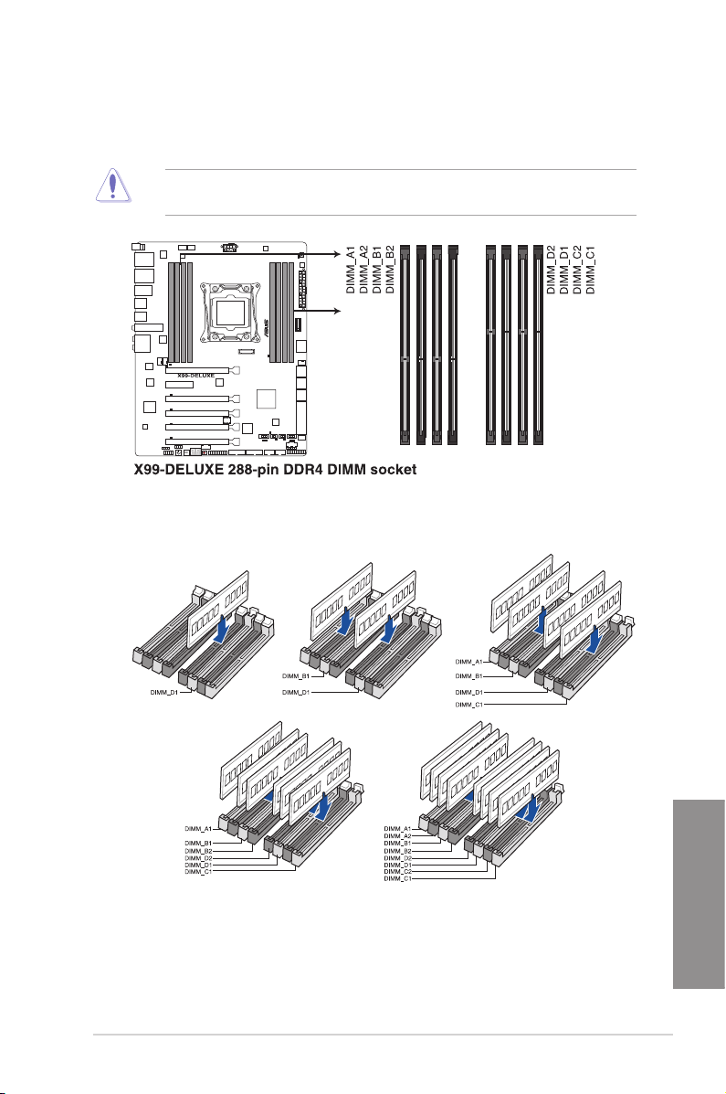
1.2.4 System memory
The motherboard comes with eight DDR 4 (Double Data Rate 4) Quad Inline Memory
Modules (DIMM) slots.
A DDR4 module is notched differently from a DDR, DDR2, or DDR3 module. DO NOT
install a DDR, DDR2, or DDR3 memory module to the DDR4 slot.
Recommended memory configurations
ASUS X99-DELUXE Series
Chapter 1
1-7

Memory configurations
You may install 2 GB, 4 GB and 8 GB unbuffered and non-ECC DDR4 DIMMs into the DIMM
sockets.
• You may install varying memory sizes in Channel A, Channel B, Channel C, and
Channel D. The system maps the total size of the lower-sized channel for the quad-
channel conguration. Any excess memory from the higher-sized channel is then
mapped for single-channel operation.
• According to Intel® CPU spec, DIMM voltage below 1.65 V is recommended to protect
the CPU.
• Due to the memory address limitation on 32-bit Windows® OS, when you install 4GB
or more memory on the motherboard, the actual usable memory for the OS can be
about 3GB or less. For effective use of memory, we recommend that you do any of the
following:
a) Use a maximum of 3GB system memory if you are using a 32-bit Windows
b) Install a 64-bit Windows® OS when you want to install 4 GB or more on the
motherboard.
c) For more details, refer to the Microsoft® support site at http://support.microsoft.
com/kb/929605/en-us.
• The default memory operation frequency is dependent on its Serial Presence Detect
(SPD), which is the standard way of accessing information from a memory module.
Under the default state, some memory modules for overclocking may operate at a
lower frequency than the vendor-marked value. To operate at the vendor-marked
or at a higher frequency, refer to section 3.5 Ai Tweaker menu for manual memory
frequency adjustment.
• For system stability, use a more efcient memory cooling system to support a full
memory load (8 DIMMs) or overclocking condition.
• Memory modules with memory frequency higher than 2133MHz and their
corresponding timing or the loaded XMP prole is not the JEDEC memory standard.
The stability and compatibility of the memory modules depend on the CPU’s
capabilities and other installed devices.
• Always install the DIMMS with the same CAS Latency. For an optimum compatibility,
we recommend that you install memory modules of the same version or data code
(D/C) from the same vendor. Check with the vendor to get the correct memory
modules.
®
OS.
Chapter 1
1-8
Chapter 1: Product introduction
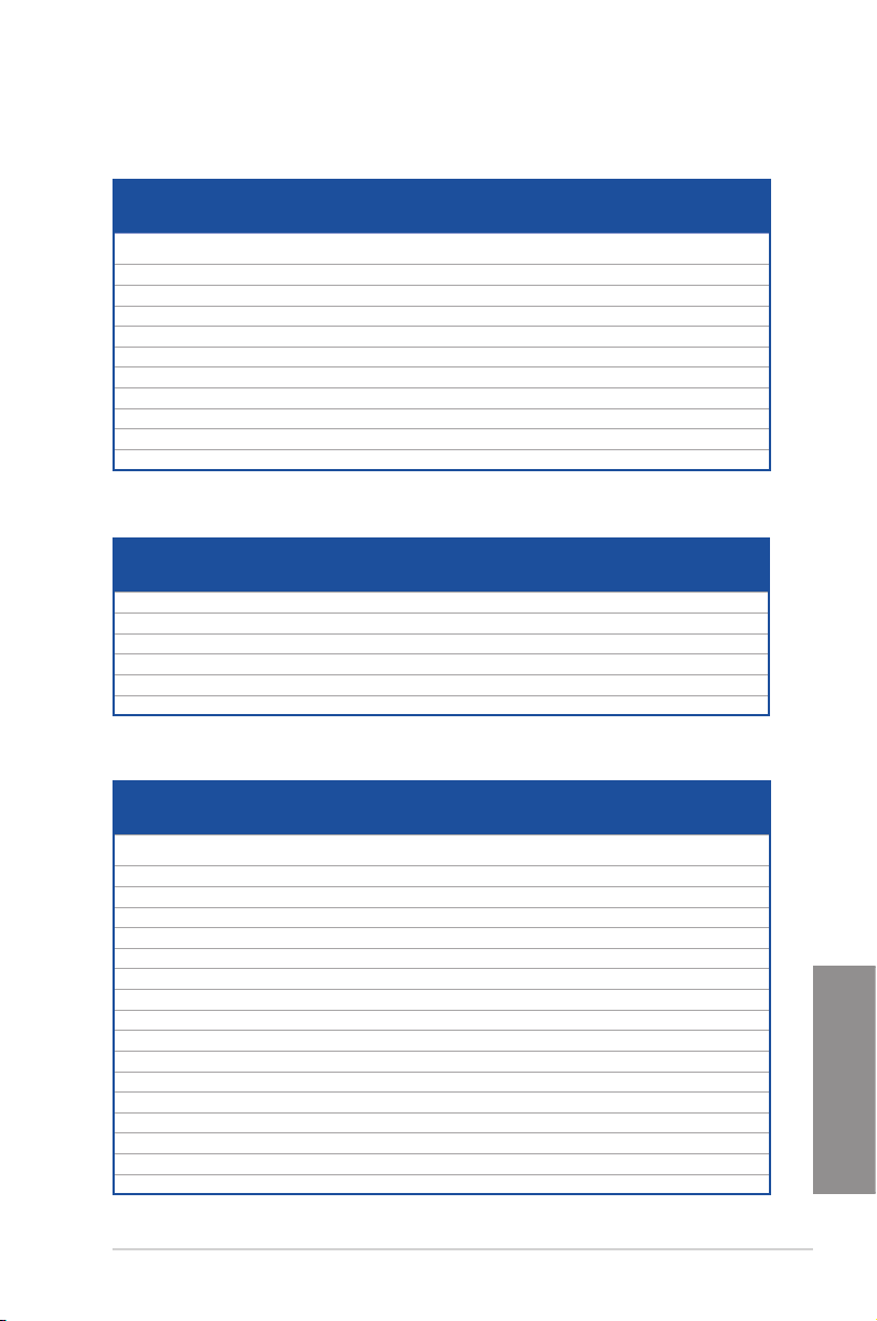
X99-DELUXE Motherboard Qualified Vendors Lists (QVL)
DDR3 2800 MHz capability
Vendors Part No. Size SS/DSChip
A_DATA AX4U2800W8G17-DRZ 8GB DS Hynix H5AN4G
CORSAIR CMD16GX4M4A2800C16 16GB (4GBx4) SS - - 16-18-18-36 1.2V • •
CORSAIR CMD32GX4M4A2800C16 32GB (8GBx4) DS - - 16-18-18-36 1.2V • •
CORSAIR CMD64GX4M8A2800C16 64GB (8GBx8) DS - - 16-18-18-36 1.2V • • • •
CORSAIR CMD16GX4M4A2800C15 16GB (4GBx4) SS - - 15-17-17-36 1.2V • •
CORSAIR CMD32GX4M4A2800C15 32GB (8GBx4) DS - - 15-17-17-36 1.2V • •
CORSAIR CMK16GX4M4A2800C16 16GB (4GBx4) SS - - 16-18-18-36 1.2V • •
CORSAIR CMK32GX4M4A2800C16 32GB (8GBx4) DS - - 16-18-18-36 1.2V • •
CORSAIR CMK64GX4M8A2800C16 64GB (8GBx8) DS - - 16-18-18-36 1.2V • • • •
CORSAIR CMK16GX4M4A2800C15R 16GB (4GBx4) SS - - 15-17-17-36 1.2V • •
CORSAIR CMK32GX4M4A2800C15R 32GB (8GBx4) DS - - 15-17-17-36 1.2V • •
Brand
Chip
Timing Voltage DIMM socket support
NO.
17-18-18-36 1.2V • •
8NMFR
(Optional)
2 4 6 8
DDR3 2666 MHz capability
Vendors Part No. Size SS/DSChip
CORSAIR CMD16GX4M4A2666C14 16GB (4GBx4) SS - - 14-16-16-35 1.2V • •
CORSAIR CMD32GX4M4A2666C14 32GB (8GBx4) DS - - 14-16-16-35 1.2V • •
CORSAIR CMK16GX4M4A2666C15 16GB (4GBx4) SS - - 15-17-17-35 1.2V • •
CORSAIR CMK32GX4M4A2666C15 32GB (8GBx4) DS - - 15-17-17-35 1.2V • •
CORSAIR CMK16GX4M4A2666C14R 16GB (4GBx4) SS - - 14-16-16-35 1.2V • •
CORSAIR CMK32GX4M4A2666C14R 32GB (8GBx4) DS - - 14-16-16-35 1.2V • •
Brand
Chip
Timing Voltage DIMM socket support
NO.
(Optional)
2 4 6 8
DDR3 2400 MHz capability
Vendors Part No. Size SS/DSChip
A_DATA AX4U2400W8G16-DRZ 8GB SS SK hynix H5AN4G
CORSAIR CMD16GX4M4A2400C14 16GB (4GBx4) SS - - 14-16-16-31 1.2V • •
CORSAIR CMD32GX4M4A2400C14 32GB (8GBx4) DS - - 14-16-16-31 1.2V • •
CORSAIR CMD64GX4M8A2400C14 64GB (8GBx8) DS - - 14-16-16-31 1.2V • • • •
CORSAIR CMD16GX4M4A2400C13 16GB (4GBx4) SS - - 13-15-15-31 1.2V • •
CORSAIR CMD32GX4M4A2400C13 32GB (8GBx4) DS - - 13-15-15-31 1.2V • •
CORSAIR CMK16GX4M4A2400C14B 16GB (4GBx4) SS - - 14-16-16-31 1.2V • •
CORSAIR CMK16GX4M4A2400C14R 16GB (4GBx4) SS - - 14-16-16-31 1.2V • •
CORSAIR CMK16GX4M4A2400C14 16GB (4GBx4) SS - - 14-16-16-31 1.2V • •
CORSAIR CMK32GX4M4A2400C14 32GB (8GBx4) DS - - 14-16-16-31 1.2V • •
CORSAIR CMK64GX4M8A2400C14 64GB (8GBx8) DS - - 14-16-16-31 1.2V • • • •
CORSAIR CMK16GX4M4A2400C13R 16GB (4GBx4) SS - - 13-15-15-31 1.2V • •
CORSAIR CMK32GX4M4A2400C13R 32GB (8GBx4) DS - - 13-15-15-31 1.2V • •
panram PUD42400C154GNJK 4GB SS - - 15-15-15-36 1.2V • •
panram PUD42400C158GNJK 8GB DS - - 15-15-15-36 1.2V • •
panram PUD42400C154G2NJK 8GB (4GBx2) SS - - 15-15-15-36 1.2V • •
panram PUD42400C158G2NJK 16GB (8GBx2) DS - - 15-15-15-36 1.2V • •
Chip NO. Timing Voltage DIMM socket support
Brand
16-16-16-39 1.2V • •
8NMFR
(Optional)
2 4 6 8
Chapter 1
ASUS X99-DELUXE Series
1-9
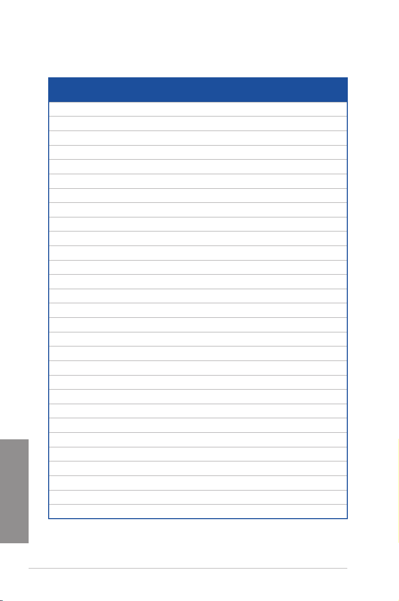
DDR3 2133 MHz capability
Vendors Part No. Size SS/DSChip
Micron MTA8ATF51264AZ-
Micron MTA16ATF1G64AZ-
Crucial CT4G4DFS8
Crucial CT8G4DFD8
Samsung M378A5143DB0-CPB 4GB SS Samsung K4A4G08
SK hynix HMA451U6MF
SK hynix HMA41GU6MF
A_DATA AX4U2133W4
A_DATA AX4U2133W8
A_DATA AX4U2133W4
A_DATA AX4U2133W8
CORSAIR CMK8GX4M2
CORSAIR CMK16GX4M
CORSAIR CMK8GX4M2
CORSAIR CMK16GX4M
CORSAIR CMK16GX4M
CORSAIR CMK16GX4M4
CORSAIR CMK32GX4M4
CORSAIR CMK64GX4M8
CORSAIR CMK16GX4M4
CORSAIR CMK32GX4M4
CORSAIR CMD16GX4M4
CORSAIR CMD32GX4M4
Kingston KVR21N15/8 8GB DS SK hynix H5AN4G8N
Chapter 1
panram PUD42133C1
panram PUD42133C1
panram PUD42133C1
panram PUD42133C1
SUPER
TALENT
Chip NO. Timing Voltage DIMM socket support
Brand
2G1A1
2G1A1
213.8FA1
213.16FA1
R8N-TF
R8N-TF
G13-DRZ
G13-DRZ
G15-DRZ
G15-DRZ
A2133C15
2A2133C15
A2133C15R
4A2133C13B
4A2133C13R
A2133C13
A2133C13
A2133C13
A2133C12R
A2133C12R
A2133C12
A2133C12
54GNJK
58GNJK
54G2NJK
58G2NJK
FBU2B008GM 8GB DS - - 15-15-15-36 1.2V • • • •
4GB SS Micron D9RGQ 15-15-15-37 1.2V • • • •
8GB DS Micron D9RGQ 15-15-15-37 1.2V • • • •
4GB SS Micron D9RGQ 15-15-15-37 1.2V • • • •
8GB DS Micron D9RGQ 15-15-15-37 1.2V • • • •
15-15-15-37 1.2V • • • •
4GB SS SK hynix H5AN4G8
8GB DS SK hynix H5AN4G8
4GB SS SK hynix H5AN4G8
8GB DS SK hynix H5AN4G8
4GB SS SK hynix H5AN4G8
8GB DS SK hynix H5AN4G8
8GB
SS - - 15-15-15-36 1.2V • •
(4GBx2)
16GB
DS - - 15-15-15-36 1.2V • •
(8GBx2)
8GB
SS - - 15-15-15-36 1.2V • •
(4GBx2)
16GB
SS - - 13-15-15-28 1.2V • •
(4GBx4)
16GB
SS - - 13-15-15-28 1.2V • •
(4GBx4)
16GB
SS - - 13-15-15-28 1.2V • •
(4GBx4)
32GB
DS - - 13-15-15-28 1.2V • •
(8GBx4)
64GB
DS - - 13-15-15-28 1.2V • • • •
(8GBx8)
16GB
SS - - 12-14-14-27 1.2V • •
(4GBx4)
32GB
DS - - 12-14-14-27 1.2V • •
(8GBx4)
16GB
SS - - 12-14-14-27 1.2V • •
(4GBx4)
32GB
DS - - 12-14-14-27 1.2V • •
(8GBx4)
4GB DS - - 15-15-15-36 1.2V • •
8GB DS - - 15-15-15-36 1.2V • •
8GB
SS - - 15-15-15-36 1.2V • •
(4GBx2)
16GB
DS - - 15-15-15-36 1.2V • •
(8GBx2)
5WD-BCPB
15-15-15-37 1.2V • • • •
NMFRTFC
15-15-15-37 1.2V • • • •
NMFRTFC
13-13-13-36 1.2V • •
NMFR
13-13-13-36 1.2V • •
NMFR
15-15-15-37 1.2V • •
NMFR
15-15-15-37 1.2V • •
NMFR
15-15-15-37 1.2V • •
MFRTFC
(Optional)
2 4 6 8
1-10
Chapter 1: Product introduction
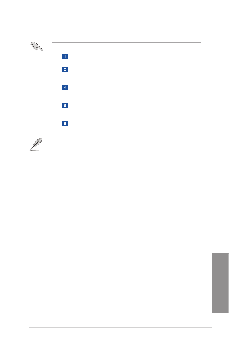
• Side(s): SS - Single-sided DS - Double-sided DIMM support:
Supports one (1) module inserted into any slot as Single-channel memory
conguration. We suggest that you install the module into D1 slot.
Supports two (2) modules inserted into one pair of the dark gray slots or the black
slots as one pair of quad-channel memory conguration. We suggest that you
install the modules into slots B1 and D1 for better compatibility.
Supports four (4) modules inserted into both the dark gray slots and black slots
as two pairs of quad-channel memory conguration. We suggest that you install
the modules into slots A1, B1, C1, and D1 for better compatibility.
Supports six (6) modules inserted into four dark gray slots and two black slots as
three pairs of quad-channel memory conguration. We suggest that you install
the modules into slots A1, B1, B2, C1, D1, and D2 for better compatibility.
Supports eight (8) modules inserted into all slots as fully-loaded quad-channel
memory congurations.
• The design of the DIMM fan may vary. Ensure that the DIMM fan ts to the
motherboard.
• ASUS exclusively provides hyper DIMM support function.
• Hyper DIMM support is subject to the physical characteristics of individual CPUs. Load
the X.M.P. or D.O.C.P. settings in the BIOS for the hyper DIMM support.
• Visit the ASUS website for the latest QVL.
ASUS X99-DELUXE Series
Chapter 1
1-11
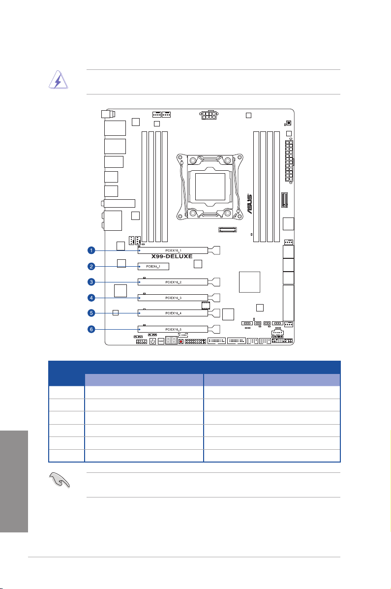
1.2.5 Expansion slots
Unplug the power cord before adding or removing expansion cards. Failure to do so may
cause you physical injury and damage motherboard components.
Slot No.
1 PCIe 3.0/2.0 x16_1 slot PCIe 3.0/2.0 x16_1 slot
2 PCIe 2.0 x4_1 slot PCIe 2.0 x4_1 slot
3 PCIe 3.0/2.0 x16_2 slot PCIe 3.0/2.0 x16_2 slot
4 PCIe 3.0/2.0 x16_3 slot PCIe 2.0 x16_3 slot
Chapter 1
1-12
5 PCIe 3.0/2.0 x16_4 slot PCIe 3.0/2.0 x16_4 slot
6 PCIe 3.0/2.0 x16_5 slot PCIe 2.0 x16_5 slot
Slot Description
40-LANE 28-LANE
If you install x8 or x16 devices to the PCIe 2.0 x4_1 slot, ensure to adjust its bandwidth in
BIOS. Refer to Chapter 3 for more information.
Chapter 1: Product introduction
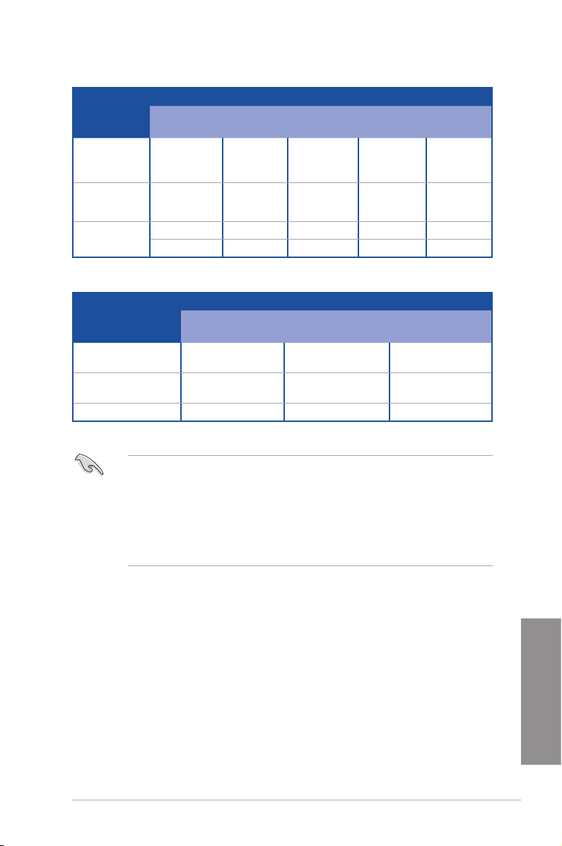
40-LANE CPU PCI Express 3.0 operating mode
VGA
configuration
Single VGA/
PCIe card
Dual VGA/PCIe
cards
Triple VGA/
PCIe cards
PCIe 3.0/2.0
x16_1
x16 (single
VGA
recommended)
PCIe 3.0/2.0
x16_2
N/A
PCIe 3.0/2.0
x16_3
x16 (single
VGA
recommended)
PCIe 3.0/2.0
x16_4
N/A N/A
x16 N/A x16 N/A N/A
x16 N/A x16 N/A x8
x8 x8 N/A x8 N/A
PCIe 3.0/2.0
x16_5
28-LANE CPU PCI Express 3.0 operating mode
VGA configuration PCIe 3.0/2.0 x16_1 PCIe 3.0/2.0 x16_2 PCIe 3.0/2.0 x16_4
Single VGA/PCIe card
x16 (single VGA
recommended)
N/A N/A
Dual VGA/PCIe cards x16 N/A x8
Triple VGA/PCIe cards x8 x8 x8
• We recommend that you provide sufcient power when running CrossFireX™ or SLI™
mode.
• Connect a chassis fan to the motherboard connector labeled CHA_FAN1-4 when
using multiple graphics cards for better thermal environment.
• For a higher performance of the 3-Way conguration using the 40-LANE CPU, adjust
the bandwidth of the PCIe x16_5 slot to x8 mode in BIOS. Refer to Chapter 3 for more
information.
Chapter 1
ASUS X99-DELUXE Series
1-13
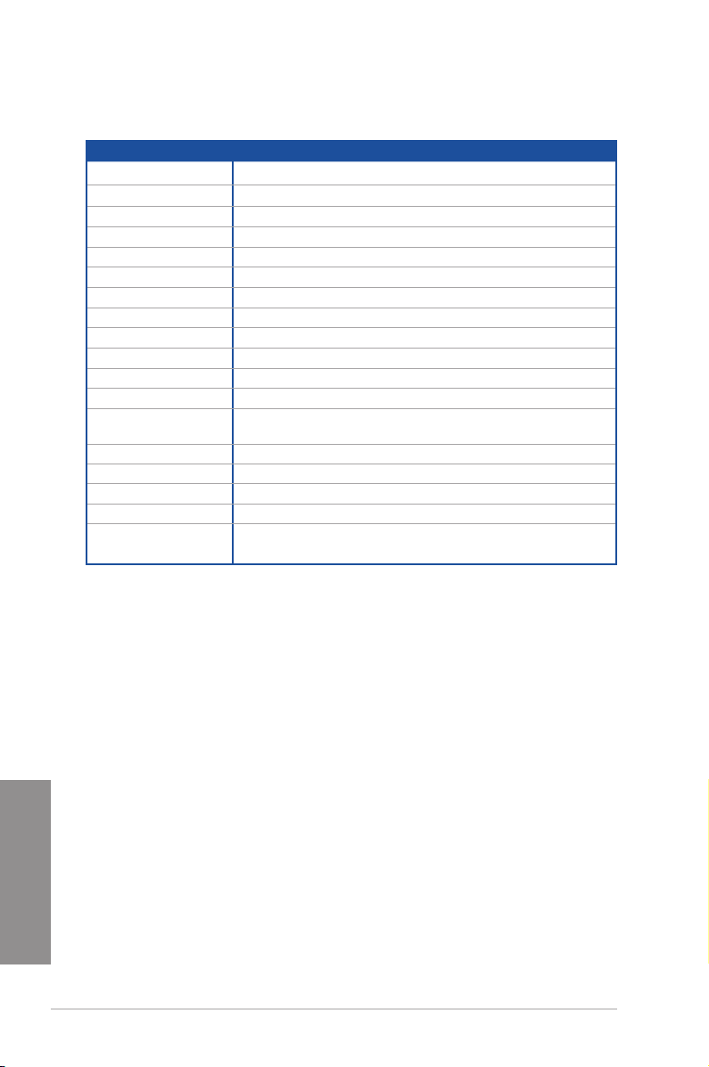
IRQ assignments for this motherboard
A B C D E F G H
PCIe x16_1 shared – – – – – – –
PCIe x16_2
PCIe x16_3 shared –
PCIe x16_4 shared –
PCIe x16_5 shared
PCIe x4_1 shared – – – – – – –
SMBUS Controller – – shared – – – – –
Wi-Fi/Bluetooth 4.0 –
Intel® SATA Controller 1
Intel® SATA Controller 2 shared – – – – – – –
Intel® LAN1 (i218)
Intel® LAN2 (i211AT) shared – – – – – – –
ASMedia SATA
Controller (106SE)
Intel® xHCI – – – – – – – shared
Intel® EHCI 1 – – – – –
Intel® EHCI 2
HD Audio – – – – – – shared –
ASMedia Controller
(1042AE)
* For 28-LANE CPUs.
shared –
shared
shared – –
–
– –
shared
–
–
– – – – – –
shared*
– –
– –
shared
–
– shared
– – – – –
–
–
shared*
–
–
– – – –
– – – –
–
– – – –
– – – –
shared
–
–
– – – –
shared
– – – –
– – – – –
– – –
–
–
–
Chapter 1
1-14
Chapter 1: Product introduction
 Loading...