

Page 1
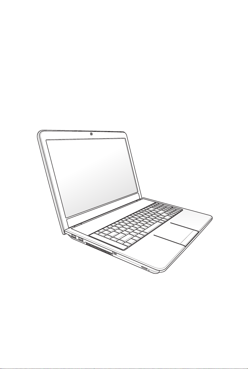
E6434
Notebook PC User Manual
April 2011
Page 2

2
Notebook PC User Manual
Table of Contents
Chapter 1: Introducing the Notebook PC
About This User’s Manual ................................................................................ 6
Notes for This Manual ....................................................................................... 6
Safety Precautions ............................................................................................. 7
Preparing your Notebook PC .......................................................................11
Chapter 2: Knowing the parts
Top Side ...............................................................................................................14
Bottom Side ........................................................................................................17
Right Side ............................................................................................................19
Left Side .............................................................................................................22
Rear Side ............................................................................................................23
Front Side ..........................................................................................................23
Chapter 3: Getting Started
Power System ....................................................................................................26
Using AC Power ...............................................................................................26
Using Battery Power ......................................................................................28
Battery Care ......................................................................................................29
Powering ON the Notebook PC .................................................................30
The Power-On Self Test (POST) ..................................................................30
Checking Battery Power ...............................................................................32
Charging the Battery Pack ...........................................................................33
Power Options .................................................................................................34
Power Management Modes .......................................................................36
Sleep and Hibernate ......................................................................................36
Thermal Power Control .................................................................................38
Special Keyboard Functions .........................................................................39
Colored Hot Keys ............................................................................................39
Microsoft Windows Keys ..............................................................................41
Multimedia Control Pad ...............................................................................42
Switches and Status Indicators ...................................................................43
Switches .............................................................................................................43
Status Indicators .............................................................................................44
Page 3

Notebook PC User Manual
3
Chapter 4: Using the Notebook PC
Pointing Device .................................................................................................48
Using the Touchpad .......................................................................................49
Touchpad Usage Illustrations .....................................................................50
Caring for the Touchpad ..............................................................................53
Automatic Touchpad Disabling .................................................................53
Storage Devices ................................................................................................55
Flash Memory Card Reader .........................................................................55
Optical Drive .....................................................................................................56
Hard Disk Drive ................................................................................................60
Memory (RAM) .................................................................................................63
Connections .......................................................................................................64
Network Connection .....................................................................................64
Wireless LAN Connection (on selected models) .................................66
Antenna Connections (on selected models) ........................................68
Windows Wireless Network Connection ................................................70
Bluetooth Wireless Connection(on selected models) .......................72
Connecting Subwoofer (on selected models) .......................................75
USB Charger+ ....................................................................................................76
Appendix
Optional Accessories .....................................................................................A-2
Optional Connections .................................................................................A-2
Operating System and Software ...............................................................A-3
System BIOS Settings ..................................................................................A-4
Common Problems and Solutions ......................................................A-10
Recovering Your Notebook PC ............................................................... A-16
Using Recovery Partition ....................................................................... A-16
Using Recovery DVD (on selected models) ...................................... A-17
DVD-ROM Drive Information ................................................................. A-20
Blu-ray ROM Drive Information(on selected models) ................... A-22
Internal Modem Compliancy ................................................................ A-23
Declarations and Safety Statements .................................................... A-27
Federal Communications Commission Statement ........................A-27
Page 4

FCC Radio Frequency (RF) Exposure Caution Statement ............ A-28
Declaration of Conformity(R&TTE directive 1999/5/EC) .............. A-28
CE Marking ................................................................................................... A-29
IC Radiation Exposure Statement for Canada ................................. A-29
Wireless Operation Channel for Different Domains ...................... A-30
France Restricted Wireless Frequency Bands ..................................A-30
UL Safety Notices .......................................................................................A-32
Power Safety Requirement ....................................................................A-33
TV Tuner Notices ........................................................................................A-33
REACH ........................................................................................................ A-33
Nordic Lithium Cautions (for lithium-ion batteries) ...................... A-34
Optical Drive Safety Information .........................................................A-35
Laser Safety Information ......................................................................... A-35
Service warning label ............................................................................... A-35
CDRH Regulations ..................................................................................... A-35
Macrovision Corporation Product Notice ......................................... A-36
Sound Pressure warning ......................................................................... A-36
DC Fan warning .......................................................................................... A-36
Adapter Information ................................................................................. A-36
CTR 21 Approval(for Notebook PC with built-in Modem) .......... A-37
European Union Eco-label ...................................................................... A-39
ENERGY STAR complied product ......................................................... A-39
Global Environmental Regulation Compliance and Declaration
ASUS Recycling/Takeback Services ..................................................... A-40
... A-40
Copyright Information .............................................................................. A-41
Limitation of Liability ................................................................................. A-42
Service and Support ................................................................................... A-42
4
Notebook PC User Manual
Page 5

Chapter 1:
Introducing the
Notebook PC
1
Page 6

6
Notebook PC User Manual
About This User’s Manual
You are reading the Notebook PC User’s Manual. This User’s Manual
provides information regarding the various components in the
Notebook PC and how to use them. The following are major sections
of this User’s Manual:
1. Introducing the Notebook PC
Introduces you to the Notebook PC and this User’s Manual.
2. Knowing the Parts
Gives you information on the Notebook PC’s components.
3. Getting Started
Gives you information on getting started with the Notebook PC.
4. Using the Notebook PC
Gives you information on using the Notebook PC’s components.
5. Appendix
Introduces you to optional accessories and gives additional
information.
The actual bundled operating system and applications differ by
models and territories. There may be differences between your
Notebook PC and the pictures shown in this manual. Please
accept your Notebook PC as being correct.
Notes for This Manual
A few notes and warnings are used throughout this guide, allowing
you to complete certain tasks safely and effectively. These notes have
different degrees of importance as follows:
WARNING! Important information that must be followed for safe
operation.
IMPORTANT! Vital information that must be followed to prevent
damage to data, components, or persons.
TIP: Tips for completing tasks.
NOTE: Information for special situations.
Page 7
Notebook PC User Manual
7
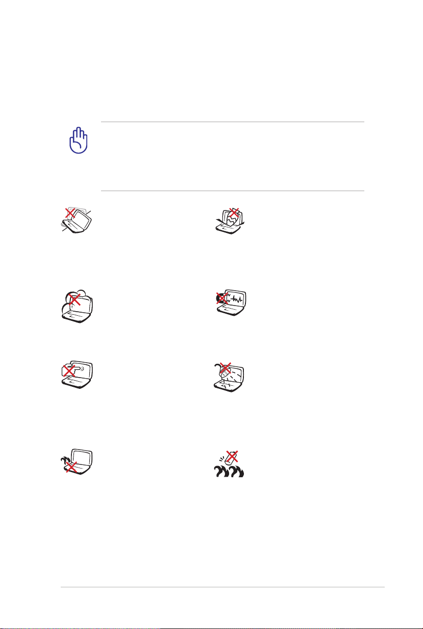
Safety Precautions
The following safety precautions will increase the life of the
Notebook PC. Follow all precautions and instructions. Except as
described in this manual, refer all servicing to qualified personnel.
Disconnect the AC power and remove the battery pack(s) before
cleaning. Wipe the Notebook PC using a clean cellulose sponge
or chamois cloth dampened with a solution of nonabrasive
detergent and a few drops of warm water and remove any extra
moisture with a dry cloth.
DO NOT place on
uneven or unstable work
surfaces. Seek servicing
if the casing has been
damaged.
DO NOT expose to dirty
or dusty environments.
DO NOT operate during a
gas leak.
DO NOT press or touch
the display panel. Do not
place together with small
items that may scratch or
enter the Notebook PC.
DO NOT leave the
Notebook PC on your lap
or any part of the body
to prevent discomfort
or injury from heat
exposure.
DO NOT place or drop
objects on top and
do not shove any
foreign objects into the
Notebook PC.
DO NOT expose to
strong magnetic or
electrical fields.
DO NOT expose to or
use near liquids, rain,
or moisture. DO NOT
use the modem during
electrical storms.
Battery safety warning:
DO NOT throw the
battery in fire. DO NOT
short circuit the contacts.
DO NOT disassemble the
battery.
Page 8
8
Notebook PC User Manual
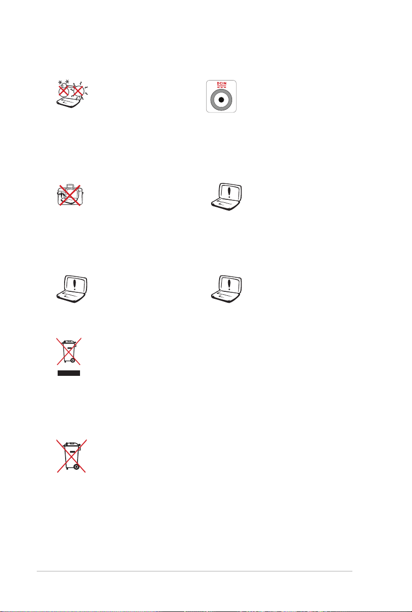
SAFE TEMP: This
Notebook PC should
only be used in
environments with
ambient temperatures
between 10°C (50°F) and
35°C (95°F).
INPUT RATING: Refer to
the rating label on the
bottom of the Notebook
PC and be sure that your
power adapter complies
with the rating.
DO NOT carry or cover
a Notebook PC that
is powered ON with
any materials that will
reduce air circulation
DO NOT use strong
solvents such as
thinners, benzene, or
other chemicals on or
near the surface.
such as a carrying bag.
DO NOT use damaged
power cords, accessories,
or other peripherals.
Incorrect installation
of battery may cause
explosion and damage
the Notebook PC.
DO NOT throw the Notebook PC in municipal waste. This
product has been designed to enable proper reuse of parts
and recycling. The symbol of the crossed out wheeled bin
indicates that the product (electrical, electronic equipment
and mercury-containing button cell battery) should not
be placed in municipal waste. Check local regulations for
disposal of electronic products.
DO NOT throw the battery in municipal waste. The symbol
of the crossed out wheeled bin indicates that the battery
should not be placed in municipal waste.
Page 9

Notebook PC User Manual
9
Sound Pressure warning
Excessive sound pressure from earphones or headphones can cause
hearing damage or loss. Adjustment of the volume control as well as
the equalizer to settings other than the center position may increase
the earphones or headphones output voltage and the sound
pressure level.
DC Fan warning
Please notice that the DC fan is a moving part that may cause
DANGER. Ensure to keep your body from the moving fan blades.
Adapter Information (vary with models)
Input voltage: 100-240V
Input frequency: 50-60Hz
Rating output current: 4.74A (90W); 6.32A (120W)
Rating output voltage: 19Vdc
Transportation Precautions
To prepare the Notebook PC for transport, you should turn it OFF
and disconnect all external peripherals to prevent damage to the
connectors. The hard disk drive’s head retracts when the power is
turned OFF to prevent scratching of the hard disk surface during
transport. Therefore, you should not transport the Notebook PC
while the power is still ON. Close the display panel and check that
it is latched securely in the closed position to protect the keyboard
and display panel.
CAUTION! The Notebook PC’s surface is easily dulled if not
properly cared for. Be careful not to rub or scrape the Notebook
PC surfaces.
Page 10

10
Notebook PC User Manual
Cover Your Notebook PC
Purchase a carrying bag to protect the Notebook PC from dirt, water,
shock, and scratches.
Charge Your Batteries
If you intend to use battery power, be sure to fully charge your
battery pack and any optional battery packs before going on long
trips. Remember that the power adapter charges the battery pack as
long as it is plugged into the computer and an AC power source. Be
aware that it takes much longer to charge the battery pack when the
Notebook PC is in use.
Airplane Precautions
Contact your airline if you want to use the Notebook PC on the
airplane. Most airlines will have restrictions for using electronic
devices. Most airlines will allow electronic use only between and not
during takeoffs and landings.
CAUTION! There are three main types of airport security
devices: X-ray machines (used on items placed on conveyor
belts), magnetic detectors (used on people walking through
security checks), and magnetic wands (hand-held devices used
on people or individual items). You can send your Notebook
PC and diskettes through airport X-ray machines. However, it
is recommended that you do not send your Notebook PC or
diskettes through airport magnetic detectors or expose them to
magnetic wands.
Page 11
Notebook PC User Manual
11
2
1
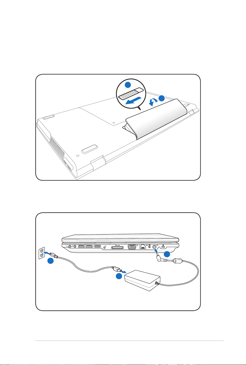
Preparing your Notebook PC
HDMI
1
2
3
110V-220V
These are only quick instructions for using your Notebook PC.
Installing the Battery Pack
Connecting the Power Adapter
Page 12
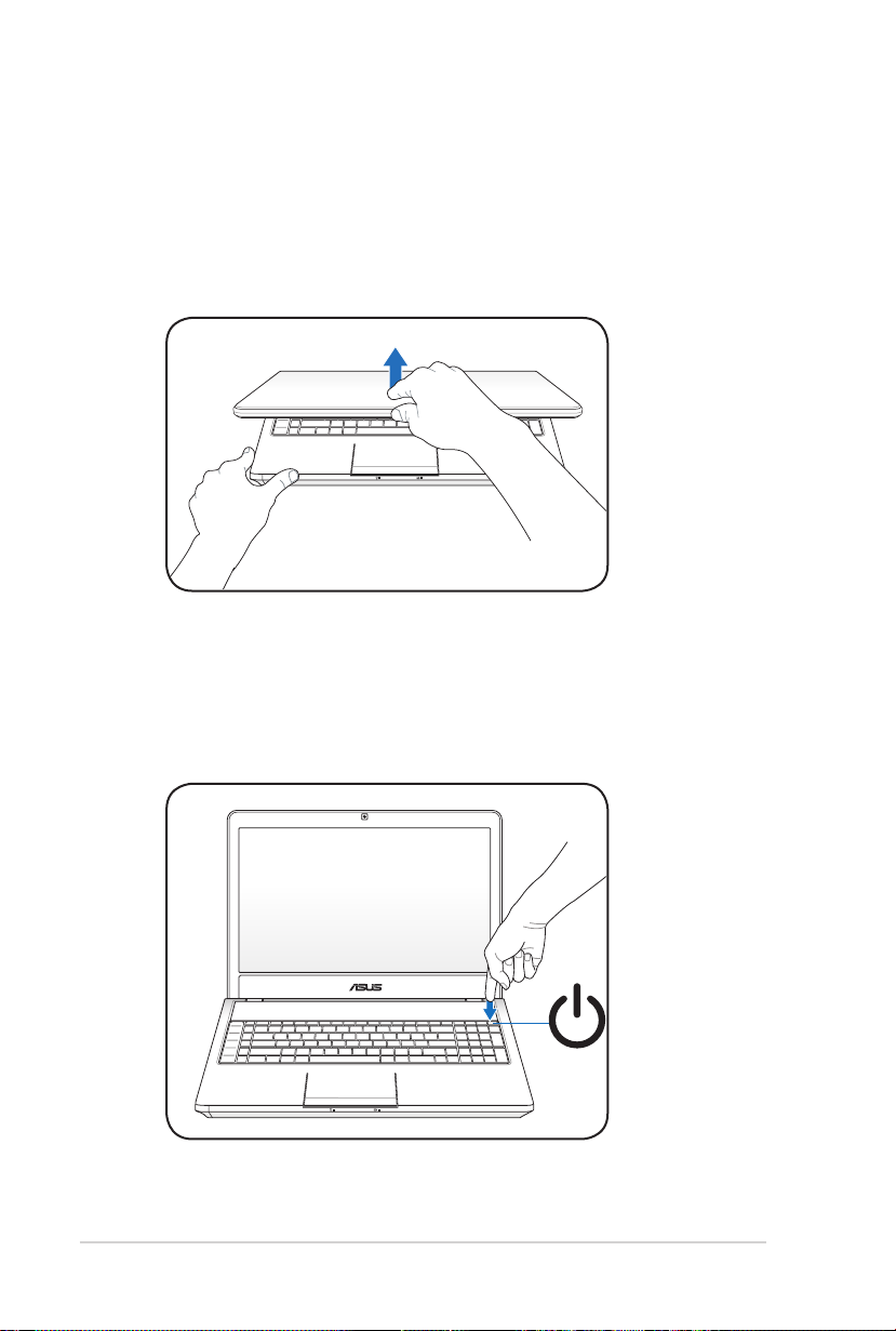
Opening the LCD display panel
1. Carefully lift up the display panel with your thumb.
2. Slowly tilt the display panel forward or backward to a
comfortable viewing angle.
Turning on the Power
1. Push and release the power button on the keyboard.
2. Use [Fn]+[F5] or [Fn]+[F6] to adjust the LCD brightness.
12
Notebook PC User Manual
Page 13

Chapter 2:
Knowing the parts
2
Page 14
14
Notebook PC User Manual
Top Side
esc
f1 f2 f3 f4 f5 f6 f7 f8 f9 f10 f11
f12
pause
prt sc
sysrq
delete
backspace
home
pgup
pgdn
enter
enter
shift
shift
ctrl
ctrl
fn
alt alt
end
break
7 8 9
4
5
6
1
2
0
3
tab
caps lock
insert
2
1
5
6
7
8
4
3
scr lk
The keyboard differs for each territory.
Page 15

Notebook PC User Manual
15
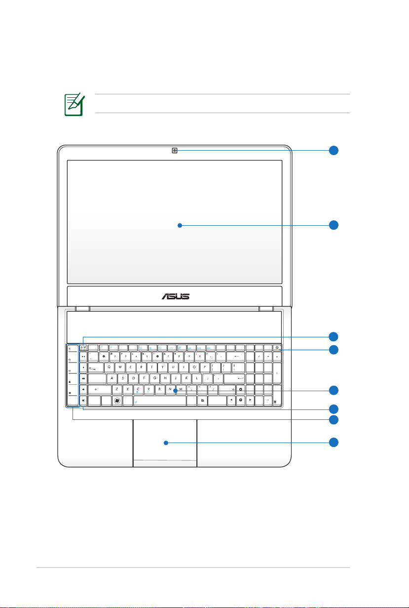
Camera
1
The built-in camera allows picture taking or video
recording. Can be used with video conferencing and other
interactive applications.
2
Display Panel
The display panel functions the same as a desktop monitor.
The Notebook PC uses an active matrix TFT LCD, which
provides excellent viewing like that of desktop monitors.
Unlike desktop monitors, the LCD panel does not produce
any radiation or flickering, so it is easier on the eyes. Use
a soft cloth without chemical liquids (use plain water if
necessary) to clean the display panel.
Instant Keys
3
Instant keys allow you to launch frequently used
applications with one push of a button. Details are
described in section 3.
4
Power Switch
The power switch turns ON and OFF the Notebook PC or
putting the Notebook PC into sleep or hibernation modes.
Actual behavior of the power switch can be customized in
Windows Control Panel “Power Options.”
5
Keyboard
The keyboard provides full-sized keys with comfortable
travel (depth at which the keys can be depressed) and
palm rest for both hands. Two Windows function keys are
provided to help ease navigation in the Windows operating
system.
Page 16

16
Notebook PC User Manual
Multimedia Keys
6
Multimedia keys allow you to activate frequently used
multimedia commands with one push of a button.
Status Indicators
7
Status indicators represent various hardware/software
conditions. See indicator details in section 3.
Touchpad and Buttons
8
The touchpad with its buttons is a pointing device that
provides the same functions as a desktop mouse. A
software-controlled scrolling function is available after
setting up the included touchpad utility to allow easy
Windows or web navigation.
Page 17
Notebook PC User Manual
17
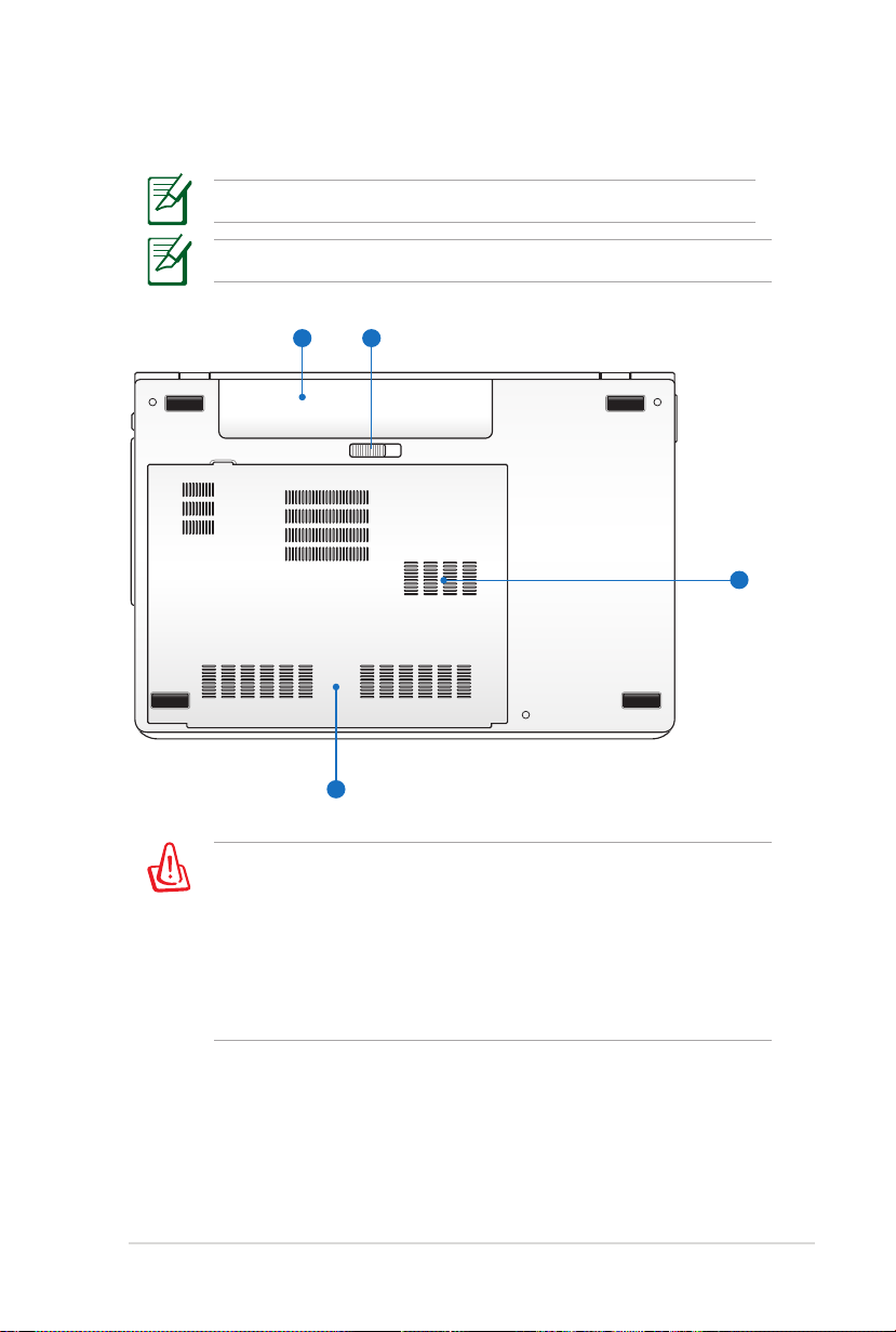
Bottom Side
1
4
3
2
The bottom side may vary in appearance depending on model.
The battery pack size varies depending on model.
The bottom of the Notebook PC can get very hot. Be careful
when handling the Notebook PC while it is in operation or
recently been in operation. High temperatures are normal during
charging or operation. DO NOT USE ON SOFT SURFACES SUCH
AS SOFAS OR BEDS, WHICH MAY BLOCK THE VENTS. DO NOT
PUT THE NOTEBOOK PC ON YOUR LAP OR OTHER PARTS OF
THE BODY TO AVOID INJURY FROM THE HEAT.
Page 18

18
Notebook PC User Manual
1
Battery Pack
The battery pack is automatically charged when the
Notebook PC is connected to an AC power source and
maintains power to the Notebook PC when AC power is
not connected. This allows use when moving temporarily
between locations. Battery time varies by usage and by
the specifications for this Notebook PC. The battery pack
cannot be disassembled and must be purchased as a single
unit.
Battery Lock - Manual
2
The manual battery lock is used to keep the battery pack
secured. Move the manual lock to the unlocked position to
insert or remove the battery pack. Move the manual lock to
the locked position after inserting the battery pack.
Memory (RAM) Compartment
3
The memory compartment provides expansion capabilities
for additional memory. Additional memory will increase
application performance by decreasing hard disk access.
The BIOS automatically detects the amount of memory in
the system and configures CMOS accordingly during the
POST (Power-On-Self-Test) process. There is no hardware or
software (including BIOS) setup required after the memory
is installed. Visit an authorized service center or retailer for
information on memory upgrades for your Notebook PC.
Only purchase expansion modules from authorized retailers
of this Notebook PC to ensure maximum compatibility and
reliability.
Hard Disk Drive Compartment
4
The hard disk drive is secured in a compartment. Visit an
authorized service center or retailer for information on hard
disk drive upgrades for your Notebook PC. Only purchase
hard disk drives from authorized retailers of this Notebook
PC to ensure maximum compatibility and reliability.
Page 19
Notebook PC User Manual
19
Right Side
HDMI
2
1
54
6
10
7 98
3
11
12
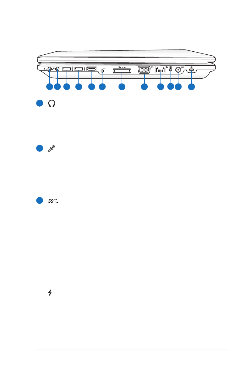
1
Headphone Output Jack
The stereo headphone jack (1/8 inch) is used to connect
the Notebook PC’s audio out signal to amplified speakers
or headphones. Using this jack automatically disables the
built-in speakers.
Microphone Input Jack
2
The mono microphone jack (1/8 inch) can be used to
connect an external microphone or output signals from
audio devices. Using this jack automatically disables the
built-in microphone. Use this feature for video conferencing,
voice narrations, or simple audio recordings.
3
USB Port (3.0) (on selected models)
The USB (Universal Serial Bus) port is compatible with USB
3.0, 2.0, or USB 1.1 devices such as keyboards, pointing
devices, cameras, hard disk drives, printers, and scanners
connected in a series up to 4.8Gbits/sec (USB 3.0),
480Mbits/sec (USB 2.0), and 12Mbits/sec (USB 1.1). USB
allows many devices to run simultaneously on a single
computer, with some peripherals acting as additional plugin sites or hubs. USB supports hot-swapping of devices so
that most peripherals can be connected or disconnected
without restarting the computer.
This port also supports USB Charger+ function that helps
charge the connected USB device even when the Notebook
PC is powered off. Refer to the E-Manual for details.
Page 20

20
Notebook PC User Manual
4
5
USB Port (3.0) (on selected models)
HDMI
HDMI Port
HDMI (High-Definition Multimedia Interface) is an
uncompressed all-digital audio/video interface between
any audio/video source, such as a set-top box, DVD player,
and A/V receiver and an audio and/or video monitor, such
as a digital television (DTV). Supports standard, enhanced,
or high-definition video, plus multi-channel digital audio
on a single cable. It transmits all ATSC HDTV standards and
supports 8-channel digital audio, with bandwidth to spare
to accommodate future enhancements or requirements.
6
Antenna Input (on selected models)
The antenna input is for TV frequency signal and allows
for use with the provided digital TV antenna or input from
subscription television services. The provided antenna can
receive digital TV.
7
Flash Memory Slot
Normally an external memory card reader must be
purchased separately in order to use memory cards from
devices such as digital cameras, MP3 players, mobile
phones, and PDAs. This Notebook PC has a built-in
high-speed memory card reader that can conveniently read
from and write to many flash memory cards.
Display (Monitor) Output
8
The 15-pin D-sub monitor port supports a standard
VGA-compatible device such as a monitor or projector to
allow viewing on a larger external display.
Page 21
Notebook PC User Manual
21
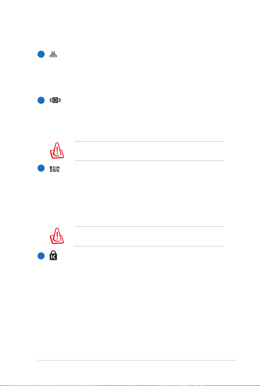
LAN Port
9
The RJ-45 LAN port with eight pins is larger than the RJ-11
modem port and supports a standard Ethernet cable for
connection to a local network. The built-in connector allows
convenient use without additional adapters.
10
Subwoofer Jack (on selected models)
The proprietary subwoofer jack is used to connect the
subwoofer that comes with your Notebook PC ONLY.
The subwoofer allows you to enjoy amazing bass (low
frequency) sounds in your multimedia applications.
DO NOT connect other device to this jack. Doing so may
damage the subwoofer jack or the Notebook PC.
11
Power (DC) Input
The supplied power adapter converts AC power to DC
power for use with this jack. Power supplied through this
jack supplies power to the Notebook PC and charges the
internal battery pack. To prevent damage to the Notebook
PC and battery pack, always use the supplied power
adapter.
The adapter may become warm to hot when in use. Ensure
not to cover the adapter and keep it away from your body.
12
Kensington® Lock Port
The Kensington® lock port allows the Notebook PC to
be secured using Kensington® compatible Notebook PC
security products. These security products usually include
a metal cable and lock that prevent the Notebook PC to
be removed from a fixed object. Some may also include a
motion detector to sound an alarm when moved.
Page 22
22
Notebook PC User Manual
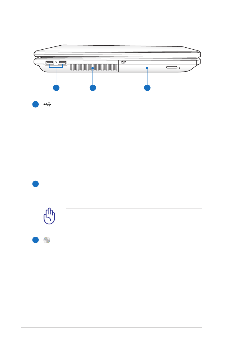
Left Side
1
2 3
1
USB Port (2.0)
The USB (Universal Serial Bus) port is compatible with USB
2.0 or USB 1.1 devices such as keyboards, pointing devices,
cameras, hard disk drives, printers, and scanners connected
in a series up to 12Mbits/sec (USB 1.1) and 480Mbits/sec
(USB 2.0). USB allows many devices to run simultaneously
on a single computer, with some peripherals acting as
additional plug-in sites or hubs. USB supports hot-swapping
of devices so that most peripherals can be connected or
disconnected without restarting the computer.
Air Vents
2
The air vents allow cool air to enter and warm air to exit the
Notebook PC.
Ensure that paper, books, clothing, cables, or other objects
do not block any of the air vents or else overheating may
occur.
Optical Drive
3
The Notebook PC comes in various models with different
optical drives. The Notebook PC’s optical drive may support
compact discs (CD) and/or digital video discs (DVD) and/or
blu-ray discs(BD) may have recordable (R) or re-writable
(RW) capabilities. See the marketing specifications for
details on each model.
Page 23
Notebook PC User Manual
23
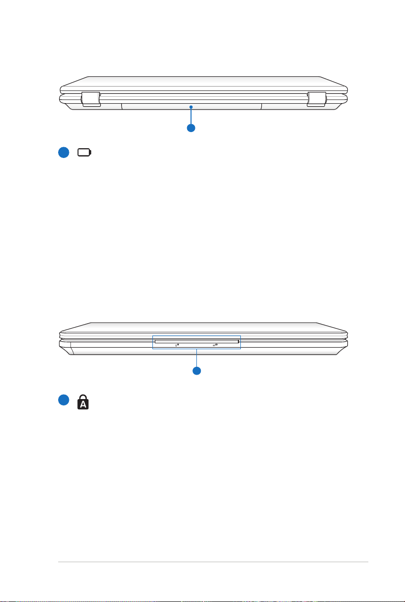
Rear Side
1
1
1
Battery Pack
The battery pack is automatically charged when the
Notebook PC is connected to an AC power source and
maintains power to the Notebook PC when AC power is
not connected. This allows use when moving temporarily
between locations. Battery time varies by usage and by
the specifications for this Notebook PC. The battery pack
cannot be disassembled and must be purchased as a single
unit.
Front Side
1
Status Indicators (front)
Status indicators represent various hardware/software
conditions.
Page 24

Page 25

Chapter 3:
Getting Started
3
Page 26
26
Notebook PC User Manual
Power System
HDMI
1
2
3
110V-220V
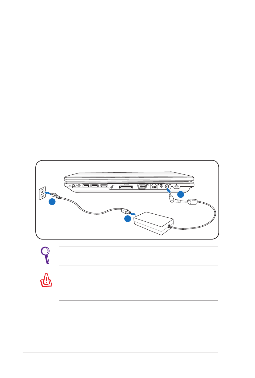
Using AC Power
The Notebook PC power is comprised of two parts, the power
adapter and the battery power system. The power adapter converts
AC power from a wall outlet to the DC power required by the
Notebook PC. Your Notebook PC comes with a universal AC-DC
adapter. That means that you may connect the power cord to any
100V-120V as well as 220V-240V outlets without setting switches
or using power converters. Different countries may require that an
adapter be used to connect the provided US-standard AC power
cord to a different standard. Most hotels will provide universal
outlets to support different power cords as well as voltages. It is
always best to ask an experienced traveler about AC outlet voltages
when bringing power adapters to another country.
You can buy travel kits for the Notebook PC that includes power
and modem adapters for almost every country.
WARNING! DO NOT connect the AC power cord to an AC outlet
prior to connecting the DC plug to the Notebook PC. Doing so
may damage the AC-DC adapter.
Page 27
Notebook PC User Manual
27
IMPORTANT! Damage may occur if you use a different adapter
to power the Notebook PC or use the Notebook PC’s adapter to
power other electrical devices. If there is smoke, burning scent,
or extreme heat coming from the AC-DC adapter, seek servicing.
Seek servicing if you suspect a faulty AC-DC adapter. You may
damage both your battery pack(s) and the Notebook PC with a
faulty AC-DC adapter.
This Notebook PC may come with either a two or three-prong
plug depending on territory. If a three-prong plug is provided,
you must use a grounded AC outlet or use a properly grounded
adapter to ensure safe operation of the Notebook PC.
WARNING! THE POWER ADAPTER MAY BECOME WARM TO HOT
WHEN IN USE. BE SURE NOT TO COVER THE ADAPTER AND KEEP
IT AWAY FROM YOUR BODY.
Unplug the power adapter or switch off the AC outlet to
minimize the power consumption when the Notebook PC is not
in use.
Page 28
28
Notebook PC User Manual
Using Battery Power
2
1
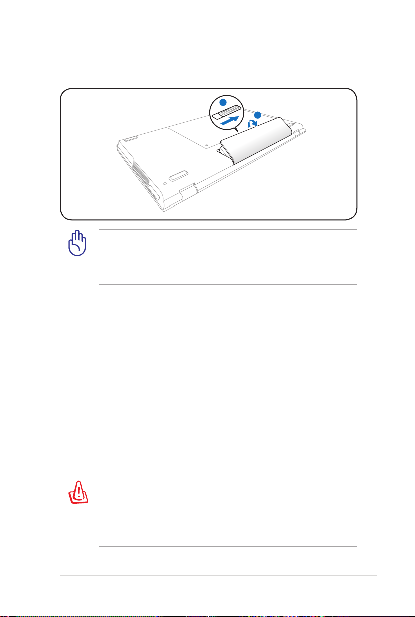
The Notebook PC is designed to work with a removable battery pack.
The battery pack consists of a set of battery cells housed together.
A fully charged pack will provide several hours of battery life, which
can be further extended by using power management features
through the BIOS setup. Additional battery packs are optional and
can be purchased separately through a Notebook PC retailer.
Installing and Removing the Battery Pack
Your Notebook PC may or may not have its battery pack installed. If
your Notebook PC does not have its battery pack installed, use the
following procedures to install the battery pack.
IMPORTANT! Never attempt to remove the battery pack while
the Notebook PC is turned ON, as this may result in the loss of
working data.
To install the battery pack:
Page 29
Notebook PC User Manual
29
To remove the battery pack:
1
2
IMPORTANT! Only use battery packs and power adapters
supplied with this Notebook PC or specifically approved by the
manufacturer or retailer for use with this model or else damage
may occur to the Notebook PC.
Battery Care
The Notebook PC’s battery pack, like all rechargeable batteries, has
a limit on the number times it can be recharged. The battery pack’s
useful life will depend on your environment temperature, humidity,
and how your Notebook PC is used. It is ideal that the battery be
used in a temperature range between 10˚C and 35˚C
(50˚F and 95˚F). You must also take into account that the Notebook
PC’s internal temperature is higher than the outside temperature.
Any temperatures above or below this range will shorten the life
of the battery. But in any case, the battery pack’s usage time will
eventually decrease and a new battery pack must be purchased
from an authorized dealer for this Notebook PC. Because batteries
also have a shelf life, it is not recommended to buy extras for storing.
WARNING! For safety reasons, DO NOT throw the battery in fire,
DO NOT short circuit the contacts, and DO NOT disassemble the
battery. If there is any abnormal operation or damage to the
battery pack caused by impact, turn OFF the Notebook PC and
contact an authorized service center.
Page 30
30
Notebook PC User Manual
Powering ON the Notebook PC
The Notebook PC’s power-ON message appears on the screen when
you turn it ON. If necessary, you may adjust the brightness by using
the hot keys. If you need to run the BIOS Setup to set or modify the
system configuration, press [F2] upon bootup to enter the BIOS
Setup. If you press [Tab] during the splash screen, standard boot
information such as the BIOS version can be seen. Press [ESC] and
you will be presented with a boot menu with selections to boot
from your available drives.
Before bootup, the display panel flashes when the power is
turned ON. This is part of the Notebook PC’s test routine and is
not a problem with the display.
IMPORTANT! To protect the hard disk drive, always wait at least
5 seconds after turning OFF your Notebook PC before turning it
back ON.
WARNING! DO NOT carry or cover a Notebook PC that is
powered ON with any materials that will reduce air circulation
such as a carrying bag.
The Power-On Self Test (POST)
When you turn ON the Notebook PC, it will first run through a
series of software-controlled diagnostic tests called the Power-On
Self Test (POST). The software that controls the POST is installed
as a permanent part of the Notebook PC’s architecture. The POST
includes a record of the Notebook PC’s hardware configuration,
which is used to make a diagnostic check of the system. This record
is created by using the BIOS Setup program. If the POST discovers
a difference between the record and the existing hardware, it will
display a message on the screen prompting you to correct the
conflict by running BIOS Setup. In most cases the record should be
correct when you receive the Notebook PC. When the test is finished,
you may get a message reporting “No operating system found” if the
hard disk was not preloaded with an operating system. This indicates
that the hard disk is correctly detected and ready for the installation
of a new operating system.
Page 31
Notebook PC User Manual
31
Self Monitoring and Reporting Technology
The S.M.A.R.T. (Self Monitoring
and Reporting Technology)
checks the hard disk drive during
POST and gives a warning
message if the hard disk drive
requires servicing. If any critical
hard disk drive warning is
given during bootup, backup
your data immediately and run
Windows disk checking program.
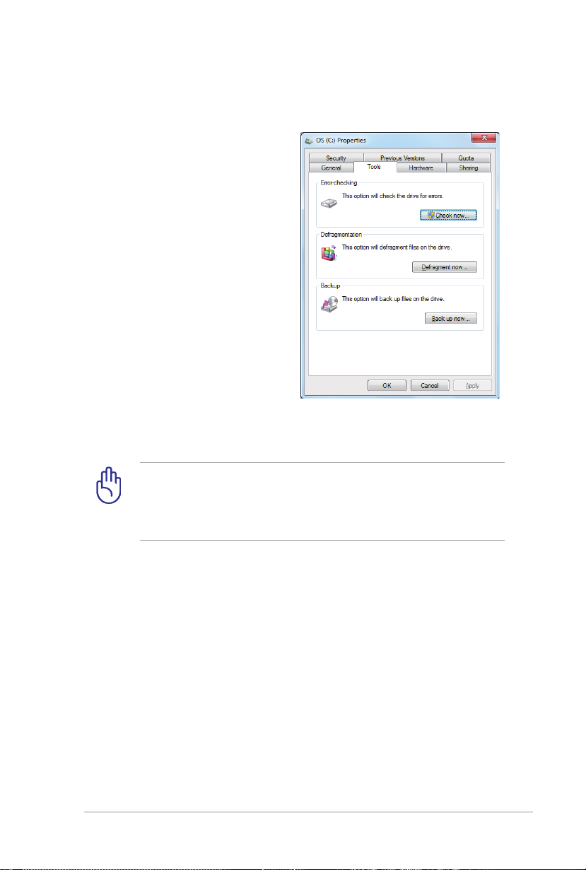
To run Window’s disk checking
program: click Windows >
select Computer > right-click
a hard disk drive icon > choose
Properties > click the Tools tab >
click Check Now > click Start. You can also select “Scan ... sectors” for
more effective scan and repair but the process will run slower.
IMPORTANT! If warnings are still given during bootup after
running a software disk checking utility, you should take your
Notebook PC in for servicing. Continued use may result in data
loss.
Page 32

32
Notebook PC User Manual
Checking Battery Power
The battery system implements the Smart Battery standard under
the Windows environment, which allows the battery to accurately
report the amount of charge left in the battery. A fully-charged
battery pack provides the Notebook PC a few hours of working
power. But the actual figure varies depending on how you use the
power saving features, your general work habits, the CPU, system
memory size, and the size of the display panel.
Screen captures shown here are examples only and may not
reflect what you see in your system.
You will be warned when battery power is low. If you continue
to ignore the low battery warnings, the Notebook PC eventually
enters suspend mode (Windows default uses STR).
Right-click the battery icon
Left-click the battery icon
Pointer over the battery icon without power adapter.
Pointer over the battery icon with
power adapter.
WARNING! Suspend-to-RAM (STR) does not last long when the
battery power is depleted. STR is not the same as power OFF.
STR requires a small amount of power and will fail and lose data
if no power is available due to complete battery depletion or
no power supply (e.g. removing both the power adapter and
battery pack).
Page 33

Notebook PC User Manual
33
Charging the Battery Pack
Before you use your Notebook PC on the road, you will have to
charge the battery pack. The battery pack begins to charge as
soon as the Notebook PC is connected to external power using the
power adapter. Fully charge the battery pack before using it for the
first time. A new battery pack must completely charge before the
Notebook PC is disconnected from external power. It takes a few
hours to fully charge the battery when the Notebook PC is turned
OFF and may take twice the time when the Notebook PC is turned
ON. The battery status indicator on the Notebook PC turns OFF when
the battery pack is charged.
The battery starts charging when the charge remaining in
the battery drops below 95%. This prevents the battery from
charging frequently. Minimizing the recharge cycles helps
prolong battery life.
The battery stops charging if the temperature is too high or the
battery voltage is too high.
WARNING! DO NOT leave the battery pack discharged. The
battery pack will discharge over time. If not using a battery pack,
it must continued to be charged every three months to extend
recovery capacity or else it may fail to charge in the future.
Page 34

34
Notebook PC User Manual
Power Options
The power switch turns ON and
OFF the Notebook PC or putting
the Notebook PC into sleep
or hibernation modes. Actual
behavior of the power switch
can be customized in Windows
Control Panel “Power Options.”
For other options, such as “Switch
User, Restart, Sleep, or Shut Down,” click the arrowhead next to the
lock icon.
Restarting or Rebooting
After making changes to your operating system, you may be
prompted to restart the system. Some installation processes will
provide a dialog box to allow restart. To restart the system manually,
choose Restart.
IMPORTANT! To protect the hard drive, wait at least 5 seconds
after turning OFF your Notebook PC before turning it back ON.
Page 35

Notebook PC User Manual
35
Emergency Shutdown
In case your operating system cannot properly turn OFF or restart,
there is an additional way to shutdown your Notebook PC:
Hold the power button over 4
seconds.
IMPORTANT! DO NOT use emergency shutdown while data is
being written; doing so can result in loss or destruction of your
data.
Page 36

36
Notebook PC User Manual
Power Management Modes
The Notebook PC has a number of automatic or adjustable power
saving features that you can use to maximize battery life and lower
Total Cost of Ownership (TCO). You can control some of these
features through the Power menu in the BIOS Setup. ACPI power
management settings are made through the operating system.
The power management features are designed to save as much
electricity as possible by putting components into a low power
consumption mode as often as possible but also allow full operation
on demand.
Sleep and Hibernate
Power management settings
can be found in the Windows
> Control Panel > Hardware
and Sound > Power Options. In
Power Options, you can define
“Sleep/Hibernate” or “Shut Down”
for closing the display panel
or pressing the power button.
“Sleep” and “Hibernate” saves power when your Notebook PC is not
in use by turning OFF certain components. When you resume your
work, your last status (such as a document scrolled down half way or
email typed half way) will reappear as if you never left. “Shut Down”
will close all applications and ask if you want to save your work if any
are not saved.
Page 37

Notebook PC User Manual
37
Sleep is the same as Suspend-toRAM (STR). This function stores
your current data and status in
RAM while many components
are turned OFF. Because RAM
is volatile, it requires power to
keep (refresh) the data. Click
the Windows button and the
arrowhead next to the lock icon
to see this option. You can also use the keyboard shortcut [Fn F1]
to activate this mode. Recover by pressing any keyboard key except
[Fn].
The power indicator will blink in Sleep mode only when the
Instant On function is not activated. You can enable or disable
Instant On based on your needs through the gadget on the
desktop of the Notebook PC.
Hibernate is the same as Suspend-to-Disk (STD) and stores your
current data and status on the hard disk drive. By doing this, RAM
does not have to be periodically refreshed and power consumption
is greatly reduced but not completely eliminated because certain
wake-up components like LAN needs to remain powered. Hibernate
saves more power compared to Sleep. Click the Windows button
and the arrowhead next to the lock icon to see this option. Recover
by pressing the power button. (NOTE: The power indicator will be
OFF in this mode.)
Page 38

38
Notebook PC User Manual
Thermal Power Control
There are three power control methods for controlling the Notebook
PC’s thermal state. These power control cannot be configured by
the user and should be known in case the Notebook PC should
enter these states. The following temperatures represent the chassis
temperature (not CPU).
• The fan turns ON for active cooling when the temperature reaches
the safe upper limit.
• The CPU decreases speed for passive cooling when the temperature
exceeds the safe upper limit.
• The system shut down for critical cooling when temperature ex-
ceeds the maximum safe upper limit.
Page 39

Notebook PC User Manual
39
Special Keyboard Functions
Colored Hot Keys
The following defines the colored hot keys
on the Notebook PC’s keyboard. The colored
commands can only be accessed by first
pressing and holding the function key while
pressing a key with a colored command.
The Hot Key locations on the function keys may vary depending
on model but the functions should remain the same. Follow the
icons instead of the function keys.
“ZZ” Icon (F1): Places the Notebook PC in suspend mode
(either Save-to-RAM or Save-to-Disk depending on sleep
button setting in power management setup).
Radio Tower (F2): Wireless Models Only: Toggles the
internal wireless LAN or Bluetooth (on selected models)
ON or OFF with an on-screen-display. When enabled,
the corresponding wireless indicator will light. Windows
software settings are necessary to use the wireless LAN
or Bluetooth.
Sun Down Icon (F5): Decreases the display brightness
Sun Up Icon (F6): Increases the display brightness
LCD Icon (F7): Toggles the display panel ON and OFF. (On
certain models; stretches the screen area to fill the entire
display when using low resolution modes.)
Page 40
40
Notebook PC User Manual
LCD/Monitor Icons (F8): Toggles between the Notebook
PC’s LCD display and an external monitor in this series:
LCD Only -> CRT Only (External Monitor) -> LCD + CRT
Clone -> LCD + CRT Extend. (This function does not
work in 256 Colors, select High Color in Display Property
Settings.) NOTE: Must connect an external monitor
“before” booting up.
Crossed-out Touchpad (F9): Toggles the built-in
touchpad LOCKED (disabled) and UNLOCKED (enabled).
Locking the touchpad will prevent you from accidentally
moving the pointer while typing and is best used with an
external pointing device such as a mouse. NOTE: Selected
models have an indicator between the touchpad buttons
will light when the touchpad is UNLOCKED (enabled) and
not light when the touchpad is LOCKED (disabled).
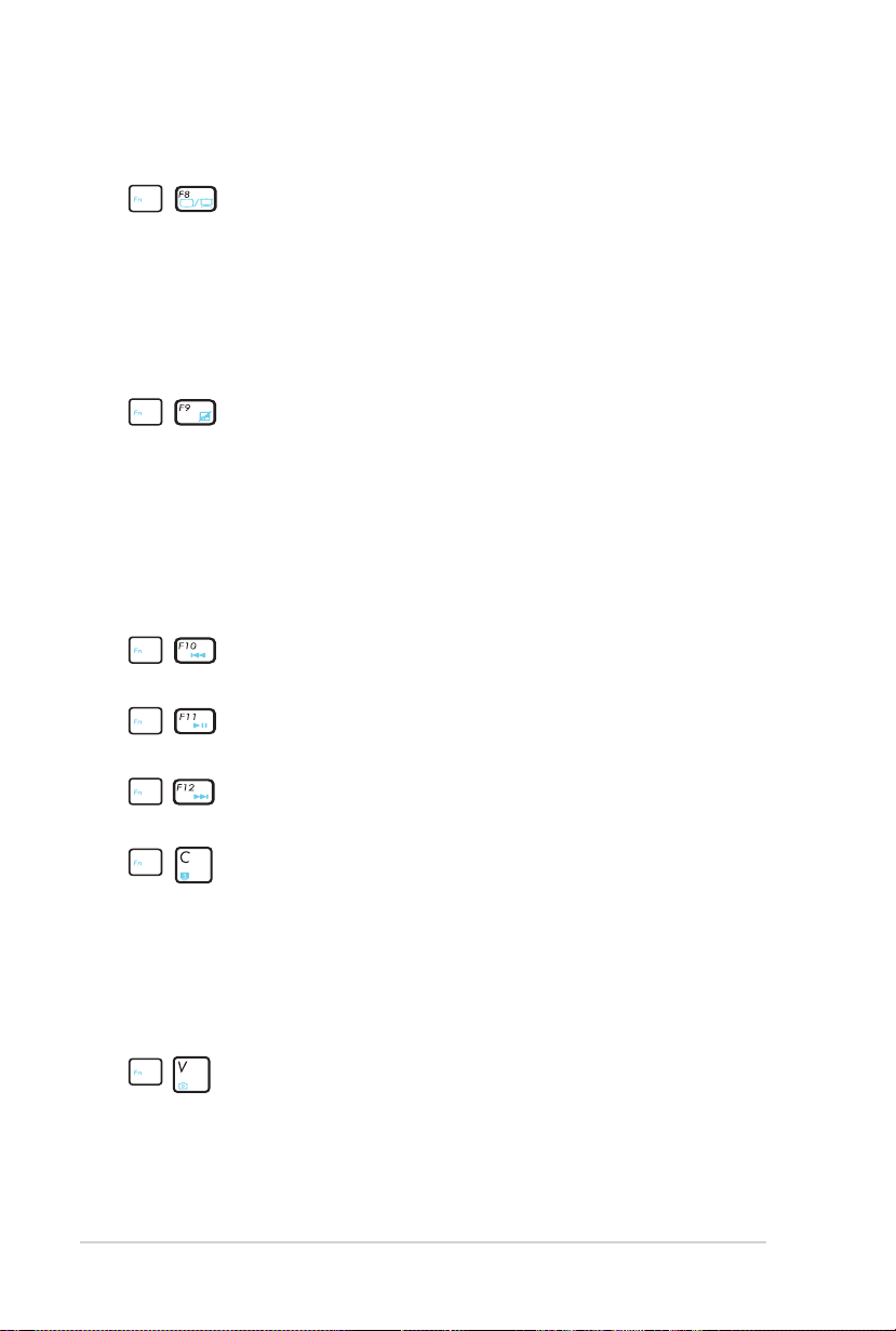
CD Skip to Previous Track (Rewind) (F10): During CD
play, skips to the previous audio track/movie chapter..
CD Play/Pause (F11): During CD stop, begins CD play.
During CD play, pauses CD play.
CD Skip to Next Track (Fast Forward) (F12): During CD
play, skips to the next audio track/movie chapter.
Fn+C: Toggles “Splendid Video Intelligent Technology”
function ON and OFF. This allows switching between
different display color enhancement modes in order
to improve contrast, brightness, skin tone, and color
saturation for red, green, and blue independently. You
can see the current mode through the onscreen display
(OSD).
Fn+V: Toggles “Life Frame” software application.
Page 41

Notebook PC User Manual
41
Power4Gear Hybrid (Fn+Space Bar): This key toggles
power savings between various power saving modes.
The power saving modes control many aspects of the
Notebook PC to maximize performance versus battery
time. Applying or removing the power adapter will
automatically switch the system between AC mode and
battery mode. You can see the current mode through the
on-screen display (OSD).
Microsoft Windows Keys
There are two special Windows keys on the keyboard as described
below.
The key with the Windows Logo activates the Start menu
located at the bottom left of the Windows desktop.
The other key, that looks like a Windows menu with
a small pointer, activates the properties menu and is
equivalent to pressing the right mouse button on a
Windows object.
Page 42

42
Notebook PC User Manual
Multimedia Control Pad
There are five control keys on the multimedia control pad on the left
of the keyboard. The following defines the meaning of each control
key on the multimedia control pad.
Play / Pause (when playing)
Stop
Increase volume
Decrease volume
Mute volume
Page 43

Notebook PC User Manual
43
Switches and Status Indicators
Switches
Music Now/ Power4Gear Hybrid Key
When your Notebook PC is powered OFF, pressing this key
will launch a multimedia player application without entering
Windows.
When your Notebook PC is powered ON, the Power4Gear Hybrid
key toggles power savings between various power saving
modes. The power saving modes control many aspects of the
Notebook PC to maximize performance versus battery time.
Applying or removing the power adapter will automatically
switch the system between AC mode and battery mode. The
selected mode is shown on the display.
Power Switch
The power switch turns ON and OFF the Notebook PC or putting
the Notebook PC into sleep or hibernation modes. Actual
behavior of the power switch can be customized in Windows
Control Panel “Power Options.”
Page 44
44
Notebook PC User Manual
Status Indicators
Left
Front
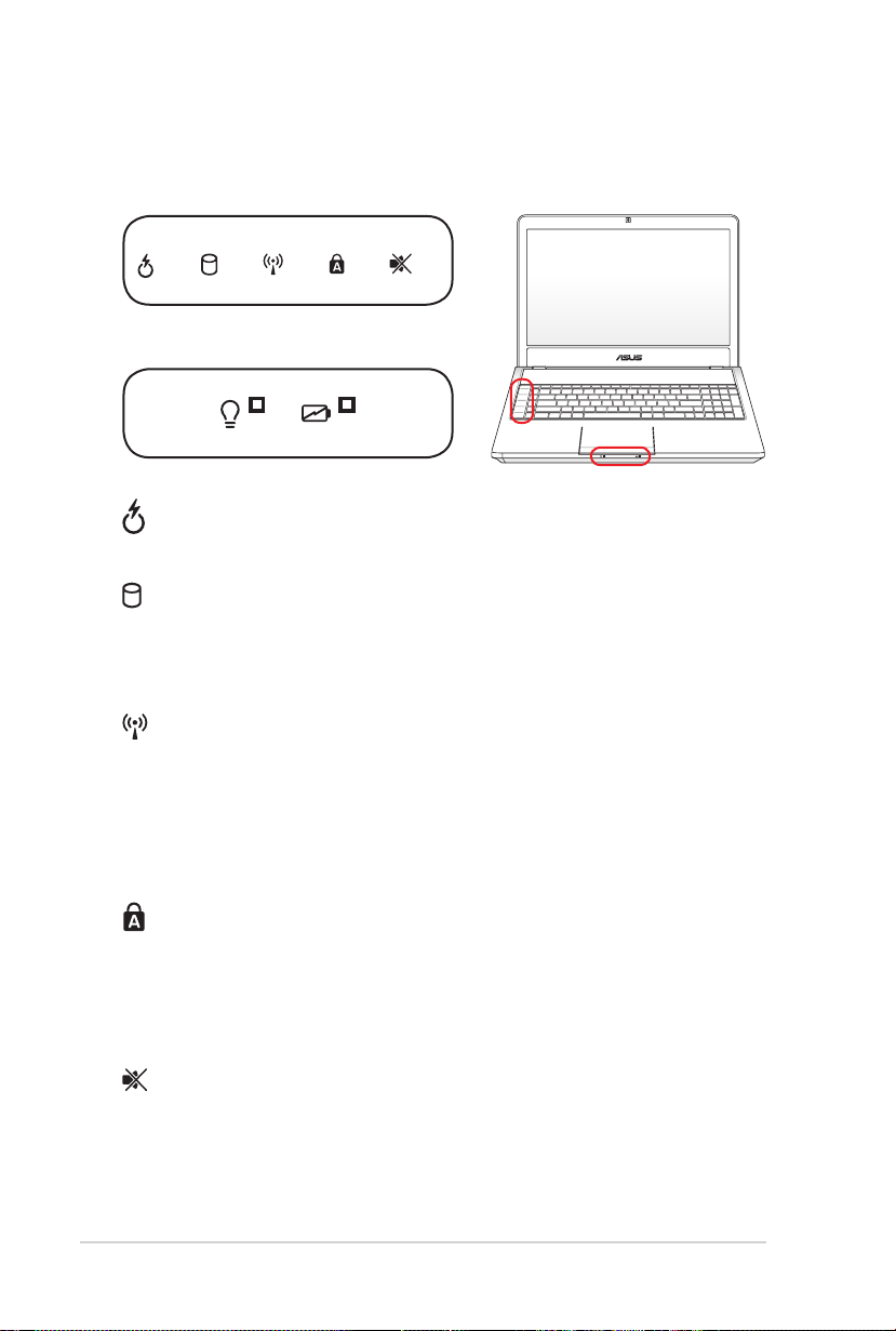
Music Now Indicator
Indicates that Music Now is activated when lighted.
Drive Activity Indicator
Indicates that the Notebook PC is accessing one or more storage
device(s) such as the hard disk. The light flashes proportional to
the access time.
Bluetooth / Wireless Indicator
This is only applicable on models with internal Bluetooth (BT)
and built-in wireless LAN. This indicator will light to show that
the Notebook PC’s built-in Bluetooth (BT) function is activated.
When the built-in wireless LAN is enabled, this indicator will also
light. (Windows software settings are necessary.)
Capital Lock Indicator
Indicates that capital lock [Caps Lock] is activated when lighted.
Capital lock allows some of the keyboard letters to type using
capitalized letters (e.g. A, B, C). When the capital lock light is OFF,
the typed letters will be in the lower case form (e.g. a,b,c).
Mute Indicator
The mute indicator lights when the volume is turn to mute.
Page 45

Notebook PC User Manual
45
Power Indicator
The power indicator lights when the Notebook PC is turned ON
and blinks slowly when the Notebook PC is in the Suspend-toRAM (Sleep) mode. This indicator is OFF when the Notebook PC
is turned OFF or in the Suspend-to-Disk (Hibernation) mode.
The power indicator will blink in Sleep mode only when the
Instant On function is not activated. You can enable or disable
Instant On based on your needs through the gadget on the
desktop of the Notebook PC.
Battery Charge Indicator (dual-color)
The dual-color battery charge indicator shows the status of the
battery’s power as follows:
Green ON: Battery power is between 95% and 100% (with AC
power).
Orange ON: Battery power is between 11% and 94% (with AC
power).
Orange Blinking: Battery power is less than 10% (with or
without AC power).
Page 46

46
Notebook PC User Manual
Page 47

Chapter 4:
Using the Notebook PC
4
Page 48

48
Notebook PC User Manual
Pointing Device
The Notebook PC’s integrated touchpad pointing device is fully
compatible with all two/three-button and scrolling knob PS/2 mice.
The touchpad is pressure sensitive and contains no moving parts;
therefore, mechanical failures can be avoided. A device driver is still
required for working with some application software.
Pointer
Movement
Right Click
Left Click
IMPORTANT! DO NOT use any objects in place of your finger
to operate the touchpad or else damage may occur to the
touchpad’s surface.
Page 49

Notebook PC User Manual
49
Using the Touchpad
The touchpad allows you to use your fingers to move the pointer
around or select onscreen items instead of using a standard
mouse. To use the touchpad, lightly press or tap your finger on the
touchpad.
Moving The Pointer
Place your finger
in the center of the
touchpad and slide in
a direction to move
the pointer.
Slide finger
left
Slide finger forward
Slide finger
right
Slide finger
backward
Page 50

50
Notebook PC User Manual
Touchpad Usage Illustrations
Clicking/Tapping - With the pointer over an item, press the left button
or use your fingertip to touch the touchpad lightly, keeping your finger
on the touchpad until the item is selected. The selected item will change
color. The following two examples produce the same results.
Clicking
Press the left pointer button
and release.
Tapping
Lightly but rapidly strike the
touchpad.
Double-clicking/Double-tapping - These actions allows you to launch
your selected program. Move your finger over the program that you
want to launch, press the left button or tap the pad twice in rapid
succession, and the system launches your selected program. If the
interval between the clicks or taps is too long, the operation will not
be executed. You can set the double-click speed using the Windows
Control Panel “Mouse.” The following two examples produce the same
results.
DoubleClicking
DoubleTapping
Press the left button twice
and release.
Lightly but rapidly strike the
touchpad twice.
Page 51

Notebook PC User Manual
51
Dragging - Dragging refers to moving an item to another location.
Move your finger over an item, while simultaneously pressing the left
button, move the item to your desired location, then release the left
button. You can also double-tap and hold the item while dragging it
with your finger. The following illustrations produce the same results.
Dragging-Clicking
Hold left button and slide
finger on touchpad.
Dragging-Tapping
Lightly strike the touchpad
twice, sliding finger on
touchpad during second strike.
Two-finger scrolling - Use two fingertips to slide up/down/left/
right on the touchpad to scroll a window up/down/left/right. If your
display window includes several sub-windows, move the pointer on
that pane before scrolling.
Vertical scrolling
Horizontal scrolling
Page 52
52
Notebook PC User Manual
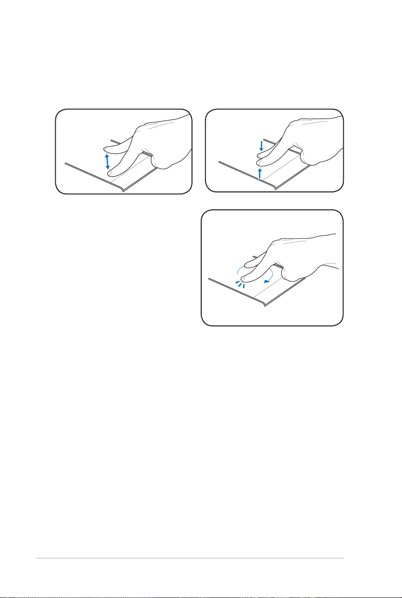
Two-finger zooming in/out - Moving two fingertips apart or
together on the touchpad to zoom in or zoom out. This is convenient
when viewing photos or reading documents.
Zoom in Zoom out
Two-finger rotating - Fix one
fingertip on the touchpad and
make an arc with the other to
rotate the photo or the document
you are viewing. You can make
a clockwise or counterclockwise
rotation based on your needs.
Page 53

Notebook PC User Manual
53
Caring for the Touchpad
The touchpad is pressure sensitive. If not properly cared for, it can be
easily damaged. Take note of the following precautions.
• Ensure the touchpad does not come into contact with dirt, liquids or
grease.
• Do not touch the touchpad if your ngers are dirty or wet.
• Do not rest heavy objects on the touchpad or the touchpad
buttons.
• Do not scratch the touchpad with your nger nails or any hard
objects.
The touchpad responds to movement not to force. There is no need
to tap the surface too hard. Tapping too hard does not increase
the responsiveness of the touchpad. The touchpad responds best
to light pressure.
Automatic Touchpad Disabling
Windows can automatically disable the Notebook PC’s touchpad
when an external USB mouse is attached.
This feature is normally OFF, to turn ON this feature:
1. Select the option in Windows Control Panel > Hardware and
Sound > Mouse.
Page 54

54
Notebook PC User Manual
2. Click Device Settings (may be labelled as the manufacturer’s
name) on the top right and click to disable the touchpad when
the external USB mouse is connected.
3. Click OK to finish the configuration.
Page 55
Notebook PC User Manual
55
Storage Devices
HDMI
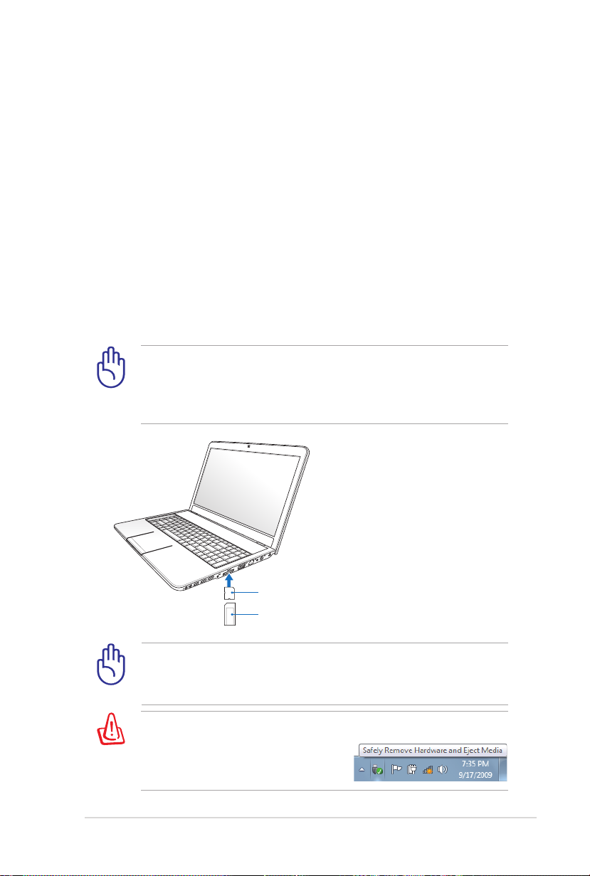
MS / MS Pro
SD / SDHC / SDXC/ MMC
Storage devices allow the Notebook PC to read or write documents,
pictures, and other files to various data storage devices.
Flash Memory Card Reader
Normally a memory card reader must be purchased separately in
order to use memory cards from devices such as digital cameras,
MP3 players, mobile phones, and PDAs. This Notebook PC has a
single built-in memory card reader that can use many flash memory
cards as shown in the example below. The built-in memory card
reader is not only convenient, but also faster than most other
forms of memory card readers because it utilizes the internal highbandwidth PCI bus.
IMPORTANT! Flash memory card compatibility varies depending
on Notebook PC model and flash memory card specifications.
Flash memory card specifications constantly change so
compatibility may change without warning.
IMPORTANT! Never remove cards while or immediately after
reading, copying, formatting, or deleting data on the card or else
data loss may occur.
WARNING! To prevent data loss, use “Safely Remove Hardware
and Eject Media” in the Windows
notification area before removing
the flash memory card.
Page 56
56
Notebook PC User Manual
Optical Drive
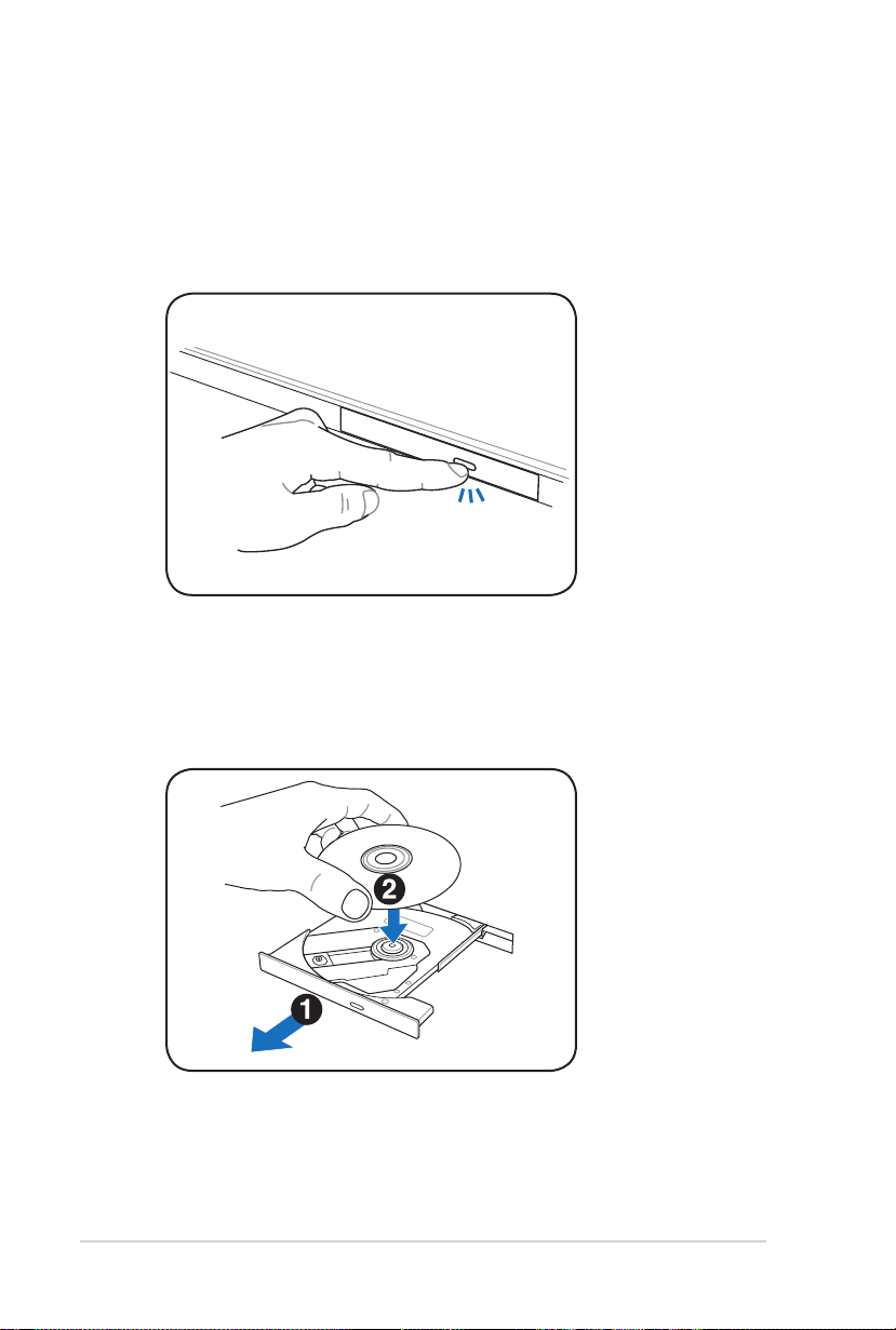
Inserting an optical disc
1. While the Notebook PC’s power is ON, press the drive’s eject
button and the tray will eject out partially.
2. Gently pull on the drive’s front panel and slide the tray
completely out. Be careful not to touch the CD drive lens and
other mechanisms. Make sure there are no obstructions that
may get jammed under the drive’s tray.
Page 57

Notebook PC User Manual
57
3. Hold the disc by the edge and face the disc’s printed side up.
Push down on both sides of the disc’s center until the disc snaps
onto the hub. The hub should be higher than the disc when
correctly mounted.
4. Slowly push the drive’s tray back in. The drive will begin reading
the table of contents (TOC) on the disc. When the drive stops,
the disc is ready to be used.
It is normal to hear as well as feel the CD spinning with great
intensity in the CD drive while data is read.
Page 58
58
Notebook PC User Manual
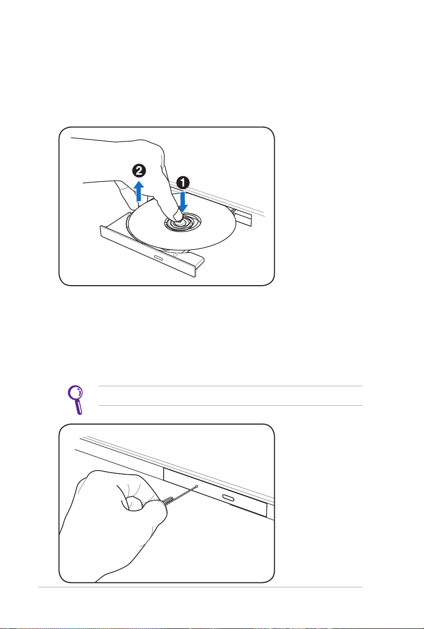
Removing an optical disc
Eject the tray and gently pry the edge of the disc upwards at an
angle to remove the disc from the hub.
Emergency eject
The emergency eject is located in a hole on the optical drive and is
used to eject the optical drive tray in case the electronic eject does
not work. Do not use the emergency eject in place of the electronic
eject.
Ensure not to stab the activity indicator located in the same area.
Actual location will vary
by model.
Page 59

Notebook PC User Manual
59
Using the Optical Drive
Optical discs and equipment must be handled with care because of
the precise mechanics involved. Keep in mind the important safety
instructions from your CD suppliers. Unlike desktop optical drives,
the Notebook PC uses a hub to hold the CD in place regardless of the
angle. When inserting a CD, it is important that the CD be pressed
onto the center hub or else the optical drive tray will scratch the CD.
WARNING! If the CD disc is not properly locked onto the center
hub, the CD can be damaged when the tray is closed. Always
watch the CD closely while closing the tray slowly to prevent
damage.
A CD drive letter should be present regardless of the presence of a
CD disc in the drive. After the CD is properly inserted, data can be
accessed just like with hard disk drives; except that nothing can be
written to or changed on the CD. Using the proper software, a CDRW drive or DVD+CD-RW drive can allow CD-RW discs to be used
like a hard drive with writing, deleting, and editing capabilities.
Vibration is normal for all high-speed optical drives due to
unbalanced CDs or CD print. To decrease vibration, use the Notebook
PC on an even surface and do not place labels on the CD.
Listening to Audio CD
The optical drives can play audio CDs, but only the DVD-ROM drive
can play DVD audio. Insert the audio CD and Windows automatically
opens an audio player and begins playing. Depending on the DVD
audio disc and installed software, it may require that you open a
DVD player to listen to DVD audio. You can adjust the volume using
hotkeys or Windows speaker icon in the Notification area.
Page 60
60
Notebook PC User Manual
Hard Disk Drive
Hard disk drives have higher capacities and operate at much faster
speeds than floppy disk drives and optical drives. The Notebook
PC comes with a replaceable hard disk drive. Current hard drives
support S.M.A.R.T. (Self Monitoring and Reporting Technology)
to detect hard disk errors or failures before they happen. When
replacing or upgrading the hard drive, always visit an authorized
service center or retailer for this Notebook PC.
IMPORTANT! Poor handling of the Notebook PC may damage
the hard disk drive. Handle the Notebook PC gently and keep it
away from static electricity and strong vibrations or impact. The
hard disk drive is the most delicate component and will likely be
the first or only component that is damaged if the Notebook PC
is dropped.
IMPORTANT! When replacing or upgrading the hard drive,
always visit an authorized service center or retailer for this
Notebook PC.
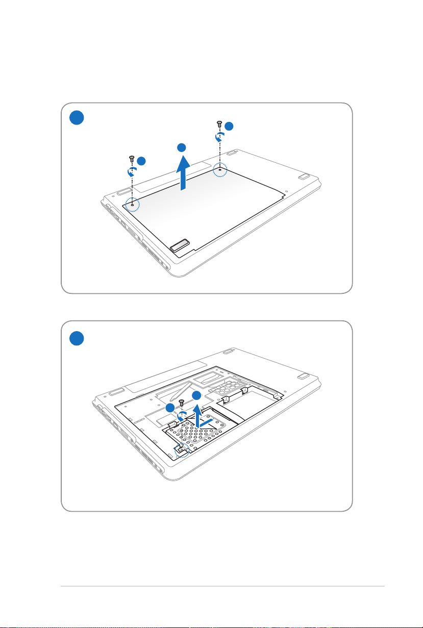
WARNING! Disconnect all the connected peripherals, any
telephone or telecommunication lines and power connector
(such as external power supply, battery pack, etc.) before
removing the hard disk cover.
The number of the hard disk drive varies with your purchased
model. The secondary hard disk drive bay may be empty
Page 61
Notebook PC User Manual
61
Removing the hard disk drives
1
1
2
1
2
1
2
Page 62

62
Notebook PC User Manual
Installing the hard disk drives
1
2
2
2
1
1
2
Page 63

Notebook PC User Manual
63
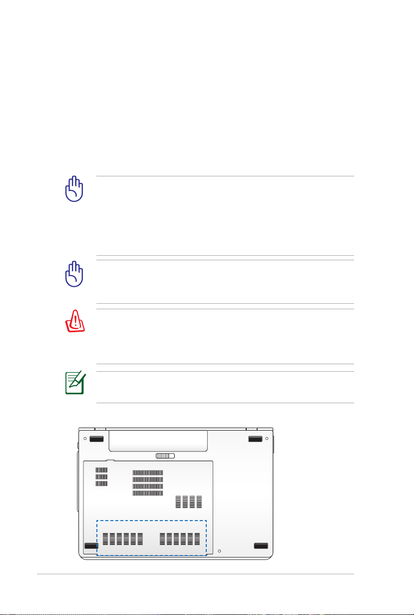
Memory (RAM)
3
3
Additional memory will increase application performance by
decreasing hard disk access. Visit an authorized service center or
retailer for information on memory upgrades for your Notebook PC.
Only purchase expansion modules from authorized retailers of this
Notebook PC to ensure maximum compatibility and reliability.
The BIOS automatically detects the amount of memory in the
system and configures CMOS accordingly during the POST (PowerOn-Self-Test) process. There is no hardware or software (including
BIOS) setup required after the memory is installed.
WARNING! Disconnect
all the connected
peripherals, any
telephone or
telecommunication lines
and power connector
(such as external power
supply, battery pack,
etc.) before installing or
removing a memory.
Installing a Memory Card:
(This is only an example.)
Removing a Memory Card:
(This is only an example.)
Page 64

64
Notebook PC User Manual
Connections
The built-in network cannot be installed later as an upgrade.
After purchase, network can be installed as an expansion card.
Network Connection
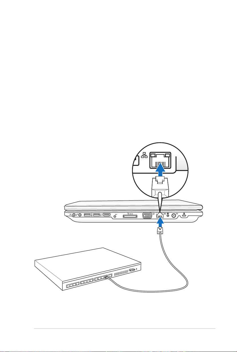
Connect a network cable, with RJ-45 connectors on each end, to the
modem/network port on the Notebook PC and the other end to a
hub or switch. For 100 BASE-TX / 1000 BASE-T speeds, your network
cable must be category 5 or better (not category 3) with twisted-pair
wiring. If you plan on running the interface at 100/1000Mbps, it must
be connected to a 100 BASE-TX / 1000 BASE-T hub (not a BASE-T4
hub). For 10Base-T, use category 3, 4, or 5 twisted-pair wiring. 10/100
Mbps Full-Duplex is supported on this Notebook PC but requires
connection to a network switching hub with “duplex” enabled. The
software default is to use the fastest setting so no user-intervention
is required.
1000BASE-T (or Gigabit) is only supported on selected models.
Page 65
Notebook PC User Manual
65
HDMI
Twisted-Pair Cable
The cable used to connect the Ethernet card to a host (generally
a Hub or Switch) is called a straight-through Twisted Pair Ethernet
(TPE). The end connectors are called RJ-45 connectors, which are
not compatible with RJ-11 telephone connectors. If connecting two
computers together without a hub in between, a crossover LAN
cable is required (Fast-Ethernet model). (Gigabit models support
auto-crossover so a crossover LAN cable is optional.)
Example of the Notebook PC connected to a Network Hub or Switch
for use with the built-in Ethernet controller.
Network Hub or Switch
Network cable with RJ-45
connectors
Page 66

66
Notebook PC User Manual
Wireless LAN Connection (on selected models)
The optional built-in wireless LAN is a compact easy-to-use wireless
Ethernet adapter. Implementing the IEEE 802.11 standard for
wireless LAN (WLAN), the optional built-in wireless LAN is capable of
fast data transmission rates using Direct Sequence Spread Spectrum
(DSSS) and Orthogonal Frequency Division Multiplexing (OFDM)
technologies on 2.4GHz/5GHz frequencies. The optional built-in
wireless LAN is backward compatible with the earlier IEEE 802.11
standards allowing seamless interfacing of wireless LAN standards.
The optional built-in wireless LAN is a client adapter that supports
Infrastructure and Ad-hoc modes giving you flexibility on your
existing or future wireless network configurations for distances up to
40 meters between the client and the access point.
To provide efficient security to your wireless communication, the
optional built-in wireless LAN comes with a 64-bit/128-bit Wired
Equivalent Privacy (WEP) encryption and Wi-Fi Protected Access
(WPA) features.
For security concerns, DO NOT connect to the unsecured
network; otherwise, the information transmission without
encryption might be visible to others.
Page 67

Notebook PC User Manual
67
Ad-hoc mode
The Ad-hoc mode allows the Notebook PC to connect to another
wireless device. No access point (AP) is required in this wireless
environment.
(All devices must install
Notebook PC
Desktop PC
optional 802.11 wireless
LAN adapters.)
PDA
Infrastructure mode
The Infrastructure mode allows the Notebook PC and other wireless
devices to join a wireless network created by an Access Point (AP)
(sold separately) that provides a central link for wireless clients to
communicate with each other or with a wired network.
(All devices must install
optional 802.11 wireless
LAN adapters.)
Notebook PC
Desktop PC
Access Point
PDA
Page 68
68
Notebook PC User Manual
Antenna Connections (on selected models)
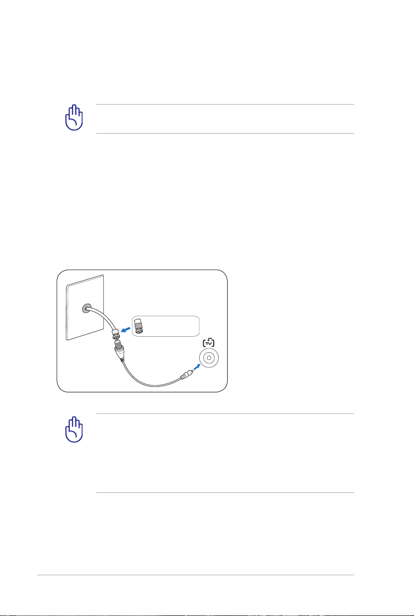
Use an NTSC to PAL
adapter if necessary.
This page shows multimedia connections for TV Tuner Models. TV
and radio features require built-in modules only on selected models.
IMPORTANT! The Notebook PC must be used indoors when
using the antenna.
Cable connection
Connect the coaxial cable from a paid television service, roofmounted aerial antenna, or indoor “rabbit ears” to the cable adapter.
Cable service connection can receive analog TV depending on paid
services. The provided adapter is necessary to change the coaxial
plug to fit the slim Notebook PC. Attach an NTSC to PAL adapter if
necessary.
IMPORTANT! Cable distribution system should be grounded
(earthed) in accordance with ANSI/NFPA 70, the National
Electrical Code (NEC), in particular Section 820.93, Grounding of
Outer Conductive Shield of a Coaxial Cable – installation should
include bonding the screen of the coaxial cable to the earth at
the building entrance.
Page 69

Notebook PC User Manual
69
DTV antenna connection
Connect the provided digital TV antenna to the Notebook PC using
the cable adapter. The digital TV antenna can only receive digital TV
signals broadcasted in selected regions.
Digital television reception is available on selected models
only and will vary by location depending on distance from
transmission towers and obstructions.
Page 70

70
Notebook PC User Manual
Windows Wireless Network Connection
Connecting to a network
1. Switch ON the Wireless function if necessary for your model (see
switches in Section 3).
2. Press [FN+F2] repeatedly
until wireless LAN icon and
Bluetooth icon are shown.
Or double click the Wireless
Console icon in Windows
notification area and select the
wireless LAN icon.
3. Click the wireless network icon with an orange star in the
Windows® Notification area.
4. Select the wireless access
point you want to connect
to from the list and click
Connect to build the
connection.
If you cannot find the
desired access point, click
the Refresh icon on
the upper right corner to
refresh and search in the
list again.
Page 71

Notebook PC User Manual
71
5. When connecting, you may have to enter a password.
6. After a connection has been established, the connection is
shown on the list.
7. You can see the wireless network icon in the Notification
area.
The crossed wireless network icon appears when you press
<Fn> + <F2> to disable the WLAN function.
Page 72

72
Notebook PC User Manual
Bluetooth Wireless Connection (on selected models)
Notebook PCs with Bluetooth technology eliminates the need for
cables for connecting Bluetooth-enabled devices. Examples of
Bluetooth-enabled devices may be Notebook PCs, Desktop PCs,
mobile phones, and PDAs.
If your Notebook PC did not come with built-in Bluetooth, you
need to connect a USB or ExpressCard Bluetooth module in
order to use Bluetooth.
Bluetooth-enabled mobile phones
You can wireless connect to your mobile phone. Depending on
your mobile phone’s capabilities, you can transfer phone book
data, photos, sound files, etc. or use it as a modem to connect to the
Internet. You may also use it for SMS messaging.
Bluetooth-enabled computers or PDAs
You can wireless connect to another computer or PDA and exchange
files, share peripherals, or share Internet or network connections.
You may also make use of Bluetooth-enabled wireless keyboard or
mouse.
Turning ON and Launching Bluetooth Utility
This process can be used to add most Bluetooth devices.
1. Switch ON the Wireless function if necessary for your model (see
switches in Section 3).
2. Press [FN+F2] repeatedly
until wireless LAN icon and
bluetooth icon are shown.
Page 73
Notebook PC User Manual
73
Or double click the Wireless
Console icon in the Windows
notification area and select the
Bluetooth icon.
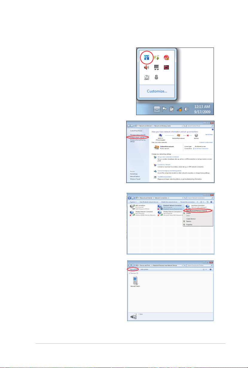
3. From Control Panel, go
to Network and Internet
> Network and Sharing
Center and then click
Change adapter settings in
the left blue pane.
4. Right-click Bluetooth
Network Connection and
select View Bluetooth
Network Devices.
5. Click Add a device to look for
new devices.
Page 74

74
Notebook PC User Manual
6. Select a Bluetooth-enabled
device from the list and click
Next.
7. Enter the Bluetooth security
code into your device and
start pairing.
8. The paired relationship is
successfully built. Click Close
to finish the setting.
Page 75
Notebook PC User Manual
75
HDMI
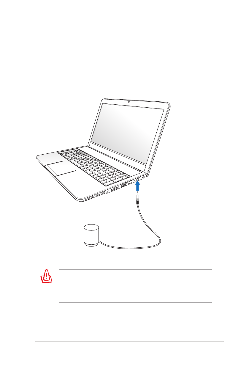
Connecting Subwoofer (on selected
models)
The subwoofer that comes with your Notebook PC is in compact
size and easy to carry. Just connect the subwoofer to the designated
subwoofer jack on your Notebook PC and enjoy amazing bass
sounds in your multimedia applications.
DO NOT force and connect this proprietary subwoofer to audio
jacks other than the designated subwoofer jack illustrated in the
user manual. Doing so may damage the subwoofer or the audio
jack.
Page 76
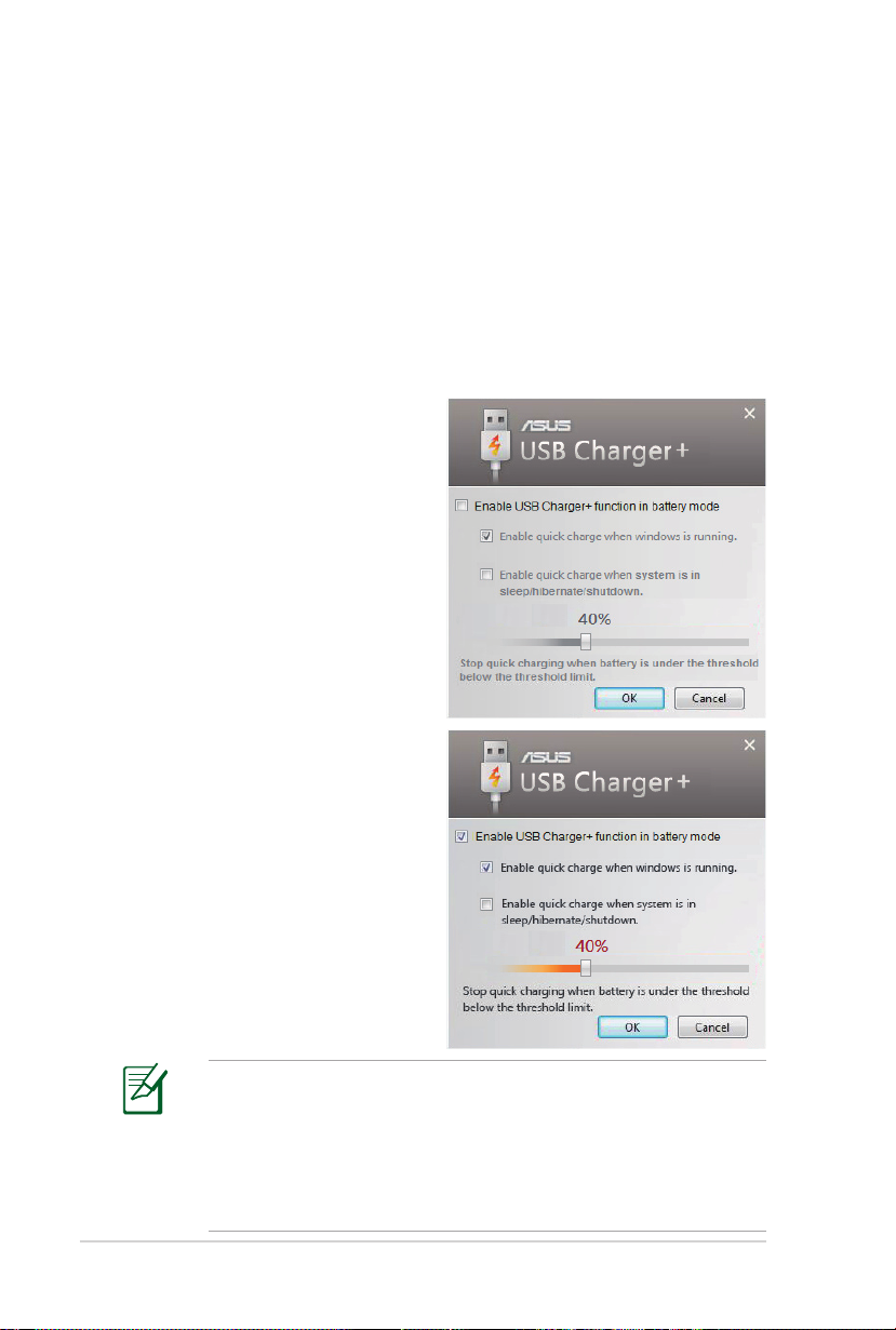
USB Charger+
USB Charger+ helps charge your USB devices compatible with
Battery Charging Version 1.1 (BC 1.1) specifications whether your
Notebook PC is powered on or off. You can decide and set the
battery threshold for stopping charging according to your needs.
With Adapter
USB Charger+ is always available on the designated USB 3.0 port
when your Notebook PC is connected with the adapter.
Without Adapter
To enable the USB Charger+
1. Click the USB Charger+ icon
in the notification area and
select Settings.
2. Click Enable USB Charger
function in battery mode.
3. According to your needs,
click to enable quick charge
when the Notebook PC is
powered ON or in sleep/
hibernation/shutdown.
4. Move the slider to set the
battery charge threshold
to stop the USB Charger+
function.
76
• The Notebook PC stops charging your connected USB device
when the battery charge drops below your set threshold.
• The USB port that supports USB Charger+ does not support
USB device wake up function.
• If your connected device is overheated, smoking, or has
abnormal odors, remove the device immediately.
Notebook PC User Manual
Page 77

Appendix
A
Page 78

A-2
Notebook PC User Manual
Optional Accessories
These items, if desired, come as optional items to complement your
Notebook PC.
USB Hub (Optional)
Attaching an optional USB hub will increase your USB ports and
allow you to quickly connect or disconnect many USB peripherals
through a single cable.
USB Flash Memory Disk
A USB flash memory disk is an optional item that can provide
storage up to several hundred megabytes, higher transfer speeds,
and greater durability. When used in current operating systems, no
drivers are necessary.
USB Floppy Disk Drive
An optional USB-interface floppy disk drive can accept a standard
1.44MB (or 720KB) 3.5-inch floppy diskette.
WARNING! To prevent system failures, use Windows “Safely
Remove Hardware” on the taskbar before disconnecting the USB
floppy disk drive. Eject the floppy disk before transporting the
Notebook PC to prevent damage from shock.
Optional Connections
These items, if desired, may be purchased from third-parties.
USB Keyboard and Mouse
Attaching an external USB keyboard will allow data entry to be more
comfortable. Attaching an external USB mouse will allow Windows
navigation to be more comfortable. Both the external USB keyboard
and mouse will work simultaneously with the Notebook PC’s built-in
keyboard and touchpad.
Printer Connection
One or more USB printers can be simultaneously used on any USB
port or USB hub.
Page 79

Notebook PC User Manual
A-3
Operating System and Software
This Notebook PC may offer (depending on territory) its customers
the choice of a pre-installed Microsoft Windows operating system.
The choices and languages will depend on the territory. The levels
of hardware and software support may vary depending on the
installed operating system. The stability and compatibility of other
operating systems cannot be guaranteed.
Support Software
This Notebook PC comes with a support disc that provides BIOS,
drivers and applications to enable hardware features, extend
functionality, help manage your Notebook PC, or add functionality
not provided by the native operating system. If updates or
replacement of the support disc is necessary, contact your dealer for
web sites to download individual software drivers and utilities.
The support disc contains all drivers, utilities and software for all
popular operating systems including those that have been preinstalled. The support disc does not include the operating system
itself. The support disc is necessary even if your Notebook PC came
pre-configured in order to provide additional software not included
as part of the factory pre-install.
A recovery disc is optional and includes an image of the original
operating system installed on the hard drive at the factory. The
recovery disc provides a comprehensive recovery solution that
quickly restores the Notebook PC’s operating system to its original
working state provided that your hard disk drive is in good working
order. Contact your retailer if you require such a solution.
Some of the Notebook PC’s components and features may not
work until the device drivers and utilities are installed.
Page 80

A-4
Notebook PC User Manual
System BIOS Settings
The BIOS screens in this section are for reference only. The actual
screens may differ by models and territories.
Boot Device
1. On the Boot screen, select Boot Option #1.
Ap tio Set up Util ity - Copy rig ht (C) 201 0 A meri can Me gatr end s, Inc.
Mai n Adv ance d Chi pse tMa in A dva nced Ch ipse t B oot Sec urit y S ave & E xit
Boo t C onf igur ati on
UEF I B oot [D isab led ]
PXE RO M [D isab led ]
Boo t O pti on P rio rit ies
Boo t O pti on # 1 [P 0: Hit ach i HT S54 5.. .]
Boo t O pti on # 2 [P 2: Sli mTy peDV D A .. .]
Har d D riv e BB S P rio riti es
CD/ DVD RO M Dr ive BB S Pr ior iti es
D elet e B oot Opt ion
Ve rsio n 2 .01 .120 8. Cop yrig ht (C) 201 0 A mer ican Me gat rend s, Inc .
2. Press [Enter] and select a device as the Boot Option #1.
En able s/D isa bles UE FI boot
fr om d isk s.
: Sel ect Sc reen
: Se lec t It em
En ter: Se lec t
+/ —: Ch ang e Op t.
F1 : Ge nera l H elp
F9 : Op timi zed De faul ts
F1 0: Sav e ES C: Ex it
Ap tio Set up Util ity - Copy rig ht (C) 201 0 A meri can Me gatr end s, Inc.
Mai n Adv ance d Chi pse tMa in A dva nced Ch ipse t B oot Sec urit y S ave & E xit
Boo t C onf igur ati on
UEF I B oot [D isab led ]
PXE RO M [D isab led ]
Boo t O pti on P rio rit ies
Boo t O pti on # 1 [P 0: Hit ach i HT S54 5.. .]
Boo t O pti on # 2 [P 2: Sli mTy peDV D A .. .]
Har d D riv e BB S P rio riti es
CD/ DVD RO M Dr ive BB S Pr ior iti es
D elet e B oot Opt ion
Ve rsio n 2 .01 .120 8. Cop yrig ht (C) 201 0 A mer ican Me gat rend s, Inc .
P0 : H ita chi HTS 545 050 B9A3 00
P2 : S lim Typ eDVD A DS8 A5SH
Di sabl ed
Bo ot O pti on #1
En able s/D isa bles Qu iet Boo t
op tion .
: Sel ect Sc reen
: Se lec t It em
En ter: Se lec t
+/ —: Ch ang e Op t.
F1 : Ge nera l H elp
F9 : Op timi zed De faul ts
F1 0: Sav e ES C: Ex it
Page 81

Notebook PC User Manual
A-5
Security Setting
Ap tio Set up Util ity - Copy rig ht (C) 201 0 A meri can Me gatr end s, Inc.
Mai n Adv ance d Boo tMa in A dva nced Bo ot S ecu rity Sa ve & Ex it
Pas swo rd Desc rip tio n
If ONL Y t he A dmi nis trat or’ s p assw ord is set ,
the n t his onl y l imi ts a cce ss to S etu p a nd i s
onl y a ske d fo r w hen ent eri ng Setu p.
If ONL Y t he u ser ’s pass wor d i s se t, the n th is
is a p owe r on pa ssw ord and mu st b e e nte red to
boo t o r e nter Se tup . In Se tup , th e U ser wil l
hav e A dmi nist rat or righ ts.
Ad min ist rato r P ass word NO T IN STA LLE D
Us er Pas swor d S tat us NO T IN STA LLE D
Se tup ad mini str ato r pa ssw ord
Us er Pas swor d
HD D P ass word St atu s : NO T IN STA LLE D
Se t M ast er P ass wor d
Se t U ser Pas swo rd
I /O I nte rfa ce S ecu rit y
Ve rsio n 2 .01 .120 8. Cop yrig ht (C) 201 0 A mer ican Me gat rend s, Inc .
To set the password:
1. On the Security screen, select Setup Administrator Password
or User Password.
2. Type in a password and press [Enter].
3. Re-type to confirm the password and press [Enter].
4. Password is then set.
Se t th e s yst em b oot or der.
: Sel ect Sc reen
: Se lec t It em
En ter: Se lec t
+/ —: Ch ang e Op t.
F1 : Ge nera l H elp
F2 : Pr evio us Val ues
F9 : Op timi zed De faul ts
F1 0: Sav e ES C: Ex it
To clear the password:
1. On the Security screen, select Setup Administrator Password
or User Password.
2. Enter the current password and press [Enter].
3. Leave the Create New Password field blank and press [Enter].
4. Leave the Confirm New Password field blank and press [Enter].
5. Password is then cleared.
You will be asked to enter the User Password whenever
you power on the Notebook PC (enter BIOS or OS). The
Administrator Password is only asked when you would like to
enter and configure the BIOS settings.
Page 82

A-6
Notebook PC User Manual
I/O Interface Security
Ap tio Set up Util ity - Copy rig ht (C) 201 0 A meri can Me gatr end s, Inc.
Sec uri ty
I/ O I nte rfac e S ecu rity
Wi rel ess Net wor k I nter fac e [U NLOC KED ]
HD AU DIO Int erf ace [U NLOC KED ]
SA TA 2nd HDD In ter face [U NLOC KED ]
SA TA ODD Int erf ace [U NLOC KED ]
U SB I nte rfa ce S ecu rit y
SA TA 2 nd HDD Int erf ace
UN LOCK ED
LO CKED
Ve rsio n 2 .01 .120 8. Cop yrig ht (C) 201 0 A mer ican Me gat rend s, Inc .
If Loc ked , 2 nd S ATA HD D wi ll be
di sabl ed.
: Sel ect Sc reen
: Se lec t It em
En ter: Se lec t
+/ —: Ch ang e Op t.
F1 : Ge nera l H elp
F9 : Op timi zed De faul ts
F1 0: Sav e ES C: Ex it
To lock the I/O interface:
1. On the Security screen, select I/O Interface Security.
2. Select an interface you would like to lock and click LOCKED.
The I/O Interface Security settings can only be altered when
you log in with Administrator privilege.
Page 83

Notebook PC User Manual
A-7
USB Interface Security
Ap tio Set up Util ity - Copy rig ht (C) 201 0 A meri can Me gatr end s, Inc.
Sec uri ty
US B I nte rfac e S ecu rity
US B I nte rfac e [U NLOC KED ]
Ex ter nal Por ts [UNL OCK ED]
Bl uet oot h [U NLOC KED ]
CM OS Cam era [ UNL OCK ED]
Ca rd Rea der [U NLOC KED ]
UN LOCK ED
LO CKED
Ve rsio n 2 .01 .120 8. Cop yrig ht (C) 201 0 A mer ican Me gat rend s, Inc .
US B In ter fac e
If Loc ked , a ll U SB dev ice wil l
be dis abl ed.
: Sel ect Sc reen
: Se lec t It em
En ter: Se lec t
+/ —: Ch ang e Op t.
F1 : Ge nera l H elp
F9 : Op timi zed De faul ts
F1 0: Sav e ES C: Ex it
To lock the USB interface:
1. On the Security screen, select I/O Interface Security > USB
Interface Security.
2. Select an interface you would like to lock and click Lock.
If you set USB Interface to [Lock], External Ports and CMOS
Camera will be locked and hidden simultaneously.
The USB Interface Security settings can only be altered when
you log in with Administrator privilege.
Page 84

A-8
Notebook PC User Manual
HDD Password
Ap tio Set up Util ity - Copy rig ht (C) 201 0 A meri can Me gatr end s, Inc.
Mai n Adv ance d Boo tMa in A dva nced Bo ot S ecu rity Sa ve & Ex it
Pas swo rd Desc rip tio n
If ONL Y t he A dmi nis trat or’ s p assw ord is set ,
the n t his onl y l imi ts a cce ss to S etu p a nd i s
onl y a ske d fo r w hen ent eri ng Setu p.
If ONL Y t he u ser ’s pass wor d i s se t, the n th is
is a p owe r on pa ssw ord and mu st b e e nte red to
boo t o r e nter Se tup . In Se tup , th e U ser wil l
hav e A dmi nist rat or righ ts.
Ad min ist rato r P ass word NO T IN STA LLE D
Us er Pas swor d S tat us NO T IN STA LLE D
Se tup ad mini str ato r pa ssw ord
Us er Pas swor d
HD D P ass word St atu s : NO T IN STA LLE D
Se t M ast er P ass wor d
Se t U ser Pas swo rd
I /O I nte rfa ce S ecu rit y
Ve rsio n 2 .01 .120 4. Cop yrig ht (C) 201 0 A mer ican Me gat rend s, Inc .
Cr eate Ne w Pa ssw ord
Se t th e s yst em b oot or der.
: Sel ect Sc reen
: Se lec t It em
En ter: Se lec t
+/ —: Ch ang e Op t.
F1 : Ge nera l H elp
F2 : Pr evio us Val ues
F9 : Op timi zed De faul ts
F1 0: Sav e ES C: Ex it
To set the HDD password:
1. On the Security screen, click Set Master Password, type in a
password and press [Enter].
2. Re-type to confirm the password and press [Enter].
3. Click Set User Password and repeat the previous steps to set
up the user password.
4. Password is then set.
• The HDD Password can only be altered when you log in with
Administrator privilege.
• You have to set Master Password before setting the User
Password.
You will be asked to enter user password first (if there is one),
then HDD user password when you power on the Notebook PC
and cannot enter the operating system if you fail to enter the
correct passwords.
Page 85
Notebook PC User Manual
A-9
Save Changes
If you want to keep your configuration settings, you must save
changes before exiting the BIOS setup utility.
Ap tio Set up Util ity - Copy rig ht (C) 201 0 A meri can Me gatr end s, Inc.
Mai n Adv ance d Chi pse t Boo tMa in A dva nced Ch ipse t B oot Sec urit y S ave & E xit
Sav e C han ges and Ex it
Dis car d C hang es and Exi t
Sav e O pti ons
Sav e C han ges
Dis car d C hang es
Res tor e D efau lts
Boo t O ver ride
P0: S T95 0042 0AS
P1: H L-D T-ST BDD VDR W CA 21N
P2: S lim Type DVD A DS8A 5SH
Lau nch EF I Sh ell fr om f ile sys tem dev ice
Ve rsio n 2 .01 .120 8. Cop yrig ht (C) 201 0 A mer ican Me gat rend s, Inc .
Ex it s yst em setu p a fte r sa vin g
th e ch ang es.
: Sel ect Sc reen
: Se lec t It em
En ter: Se lec t
+/ —: Ch ang e Op t.
F1 : Ge nera l H elp
F9 : Op timi zed De faul ts
F1 0: Sav e ES C: Ex it
Page 86

A-10
Notebook PC User Manual
Common Problems and Solutions
Hardware Problem - Optical Disc
The optical disc drive is not able to read or write discs.
1. Update the BIOS to the latest version and try again.
2. If updating the BIOS does not help, try better quality discs and
try again.
3. If the problem still exist, contact your local service center and
ask an engineer for assistance.
Unknown Reason - System Unstable
Cannot wake up from the hibernation.
1. Remove upgraded parts (RAM, HDD, WLAN, BT) if they were
installed after purchase.
2. If not the case, try MS System Restore to an earlier date.
3. If problem still persists, try restoring your system using the
recovery partition or DVD.
You must backup all your data to another location before
recovering.
4. If the problem still exist, contact your local service center and
ask an engineer for assistance.
Hardware Problem - Keyboard / Hotkey
The Hotkey (FN) is disabled.
A. Reinstall the “ATK0100” driver from the driver CD or download it
from the ASUS website.
Page 87

Notebook PC User Manual
A-11
Hardware Problem - Built-in Camera
The built-in camera does not work correctly.
1. Check “Device Manager” to see if there are any problems.
2. Try reinstalling the webcam driver to solve the problem.
3. If the problem is not solved, update the BIOS to the latest
version and try again.
4. If the problem still exist, contact your local service center and
ask an engineer for assistance.
Hardware Problem - Battery
Battery maintenance.
1. Register the Notebook PC for a one-year-warranty using the
following website:
http://member.asus.com/login.aspx?SLanguage=en-us
2. Do NOT remove the battery pack while using the Notebook
PC with the AC adaptor to prevent damage caused by the
accidental power loss. The ASUS battery pack has protection
circuitry to prevent over-charging so it will not damage the
battery pack if it is left in the Notebook PC.
Hardware Problem - Power ON/OFF Error
I cannot power ON the Notebook PC.
Diagnostics:
1. Power On by Battery only? (Y = 2, N = 4)
2. Able to see BIOS (ASUS Logo)? (Y = 3, N = A)
3. Able to load the OS? (Y = B, N = A)
4. Adapter power LED ON? (Y = 5, N = C)
5. Power ON by Adapter only? (Y = 6, N = A)
6. Able to see BIOS (ASUS Logo)? (Y = 7, N = A)
7. Able to load the OS? (Y = D, N = A)
Page 88

A-12
Notebook PC User Manual
Symptom & Solutions:
A. Problem might be in the MB, HDD, or NB; visit a local service center
for assistance.
B. Problem caused by the operating system, try restoring your system us-
ing the recovery partition or disc.
IMPORTANT! You must backup all your data to another location
before recovering.
C. Adapter problem; check the power cord connections, otherwise visit
a local service center for replacement.
D. Battery problem; please check the battery contacts, otherwise visit a
local service center for repair.
Hardware Problem - Wireless Card
How to check whether a Notebook PC is equipped with a wireless
card?
A. Enter Control Panel -> Device Manager. You will see whether
the Notebook PC has a WLAN card under the “Network Adapter”
item.
Mechanical Problem - FAN / Thermal
Why is the cooling fan always ON and the temperature high?
1. Make sure that the FAN works when the CPU temperature is
high and check whether there is air flow from the main air vent.
2. If you have many applications running (see taskbar), close them
to decrease system load.
3. The problem may also be caused by some viruses, use anti-virus
software to detect them.
4. If none of the above help, try restoring your system using the
recovery partition or DVD.
IMPORTANT! You must backup all your data to another location
before recovering.
Page 89
Notebook PC User Manual
A-13
CAUTION! DO NOT connect to the Internet before you have
installed an anti-virus software and Internet firewall to protect
yourself from viruses.
Software Problem - ASUS bundled software
When I power ON the Notebook PC, there will be an “Open policy file
error” message.
A. Reinstall the latest version “Power4 Gear” utility to solve your
problem. It is available on the ASUS website.
Unknown Reason - Blue screen with white text
A blue screen with white text appears after system bootup.
1. Remove additional memory. If additional memory was installed
after purchase, power OFF, remove the additional memory, and
power ON to see if the problem is due to incompatible memory.
2. Un-install software applications. If you have installed software
applications recently, they may not be compatible with your
system. Try to un-install them in Windows Safe Mode.
3. Check your system for viruses.
4. Update the BIOS to the latest version with Easy Flash in
Windows or AFLASH in DOS mode. These utilities and BIOS files
can be downloaded from the ASUS website.
WARNING! Ensure your Notebook PC does not lose power during
the BIOS flashing process.
Page 90

A-14
Notebook PC User Manual
5. If problem still cannot be solved, use the recovery process to
reinstall your entire system.
IMPORTANT! You must backup all your data to another location
before recovering.
CAUTION! DO NOT connect to the Internet before you have
installed an anti-virus software and Internet firewall to protect
yourself from viruses.
Ensure that you install the “Intel INF Update” and “ATKACPI”
drivers first so that hardware devices can be recognized.
6. If the problem still exist, contact your local service center and
ask an engineer for assistance.
Page 91

Notebook PC User Manual
A-15
Software Problem - BIOS
Updating the BIOS.
1. Please verify the Notebook PC’s exact model and download the
latest BIOS file for your model from the ASUS website and save
it in your flash disk drive.
2. Connect your flash disk drive to the Notebook PC and power on
the Notebook PC.
3. Use the Start Easy Flash function on the Advanced page of the
BIOS Setup Utility. Follow the instructions shown.
Ap tio Set up Util ity - Copy rig ht (C) 201 0 A meri can Me gatr end s, Inc.
Mai nMa in A dva nced Ch ipse t B oot Sec urit y S ave & E xit
ASU S F anc ySta rt [D isab led ]
POS T L ogo Typ e [S tati c]
Sta rt Eas y Fl ash
Pla y P OST Sou nd [ No]
Spe ake r V olum e [4]
Int ern al Poin tin g D evic e [E nab led]
Int el Vir tual iza tio n Te chn olo gy [E nabl ed]
VT- d [E nabl ed]
Leg acy US B Su ppo rt [ Ena bled ]
S ATA Con fig urat ion
Ve rsio n 2 .01 .120 8. Cop yrig ht (C) 201 0 A mer ican Me gat rend s, Inc .
Pr ess ENT ER to r un the uti lit y
to sel ect an d up dat e B IOS.
: Sel ect Sc reen
: Se lec t It em
En ter: Se lec t
+/ —: Ch ang e Op t.
F1 : Ge nera l H elp
F9 : Op timi zed De faul ts
F1 0: Sav e ES C: Ex it
4. Locate the latest BIOS file and start updating (flashing) the BIOS.
AS US T ek. Ea sy F las h U tili ty
FL ASH TYP E: Gene ric Fl ash Typ e
Cu rre nt Plat for m
Pl atfo rm: N75
Ve rsio n: 200
Bu ild Dat e: Mar 6 2 011
FS 0
FS 1
[ ] : Sw itc h [ ] : Cho ose [q] : E xit
New Pl atfo rm
Pl atfo rm: Unko wn
Ve rsio n: Unk own
Bu ild Dat e: Unko wn
5. You must Restore Defaults on the Exit page after updating
(flashing) the BIOS.
Page 92
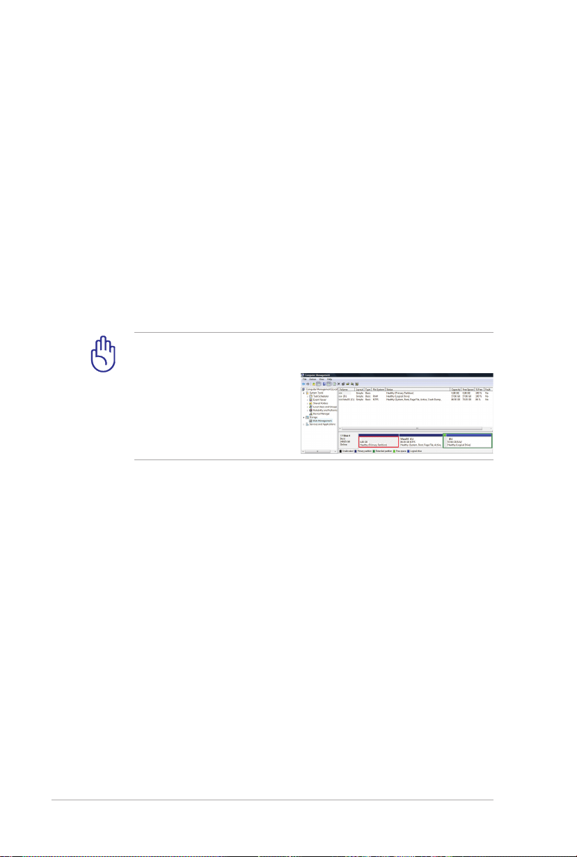
A-16
Notebook PC User Manual
Recovering Your Notebook PC
Using Recovery Partition
The Recovery Partition quickly restores your Notebook PC’s software
to its original working state. Before using the Recovery Partition, copy
your data files (such as Outlook PST files) to USB storage devices or
to a network drive and make note of any customized configuration
settings (such as network settings).
About the Recovery Partition
The Recovery Partition is a reserved space on your hard disk drive
used to restore the operating system, drivers, and utilities installed
on your Notebook PC at the factory.
IMPORTANT! DO NOT delete the partition named RECOVERY.
The Recovery Partition is created at the factory and cannot be
restored if deleted. Take
your Notebook PC to an
authorized ASUS service
center if you have problems
with the recovery process.
Using the Recovery Partition:
1. Press [F9] during bootup.
2. Press [Enter] to select Windows Setup [EMS Enabled].
3. Select the language you want to recover and click Next.
4. Read the ASUS Preload Wizard messages and click Next.
5. Select a partition option and click Next. Partition options:
Recover Windows to first partition only.
This option deletes only the first partition and allows you to keep other
partitions, and to create a new system partition as drive “C”.
Recover Windows to entire HD.
This option deletes all partitions from your hard disk drive and creates
a new system partition as drive “C”.
Page 93

Notebook PC User Manual
A-17
Recover Windows to entire HD with two partitions.
This option deletes all partitions from your hard drive and creates two
new partitions “C” (40%) and “D” (60%).
6. Follow the onscreen instructions to complete the recovery
process.
Visit the ASUS website at www.asus.com for updated drivers and
utilities.
Using Recovery DVD (on selected models)
Lock the secondary hard disk drive:
For models installed two hard disk drives, you have to lock the
secondary hard disk drive before performing system recovery with
recovery DVD.
1. Press [F2] on bootup to enter BIOS setup.
2. On the Security screen, select I/O Interface Security and press
[Enter].
Ap tio Set up Util ity - Copy rig ht (C) 201 0 A meri can Me gatr end s, Inc.
Mai n Adv ance d Boo tMa in A dva nced Bo ot S ecu rity Sa ve & Ex it
Pas swo rd Desc rip tio n
If ONL Y t he A dmi nis trat or’ s p assw ord is set ,
the n t his onl y l imi ts a cce ss to S etu p a nd i s
onl y a ske d fo r w hen ent eri ng Setu p.
If ONL Y t he u ser ’s pass wor d i s se t, the n th is
is a p owe r on pa ssw ord and mu st b e e nte red to
boo t o r e nter Se tup . In Se tup , th e U ser wil l
hav e A dmi nist rat or righ ts.
Ad min ist rato r P ass word NO T IN STA LLE D
Us er Pas swor d S tat us NO T IN STA LLE D
Se tup ad mini str ato r pa ssw ord
Us er Pas swor d
HD D U ser Pwd St atu s : N OT I NST ALL ED
HD D U ser Pwd St atu s : N OT I NST ALL ED
Se t M ast er P ass wor d
Se t M ast er P ass wor d
Se t U ser Pas swo rd
Se t U ser Pas swo rd
I /O I nte rfa ce S ecu rit y
Ve rsio n 2 .01 .120 8. Cop yrig ht (C) 201 0 A mer ican Me gat rend s, Inc .
Se t th e s yst em b oot or der.
: Sel ect Sc reen
: Se lec t It em
En ter: Se lec t
+/ —: Ch ang e Op t.
F1 : Ge nera l H elp
F2 : Pr evio us Val ues
F9 : Op timi zed De faul ts
F1 0: Sav e ES C: Ex it
Page 94

A-18
Notebook PC User Manual
3. Select SATA 2nd HDD Interface and set it to LOCKED.
Ap tio Set up Util ity - Copy rig ht (C) 201 0 A meri can Me gatr end s, Inc.
Sec uri ty
I/ O I nte rfac e S ecu rity
LA N N etw ork Int erf ace [U NLOC KED ]
Wi rel ess Net wor k I nter fac e [U NLOC KED ]
HD AU DIO Int erf ace [U NLOC KED ]
SA TA 2nd HDD In ter face [U NLOC KED ]
SA TA ODD Int erf ace [U NLOC KED ]
U SB I nte rfa ce S ecu rit y
Ve rsio n 2 .01 .120 8. Cop yrig ht (C) 201 0 A mer ican Me gat rend s, Inc .
SA TA 2 nd HDD Int erf ace
UN LOCK ED
LO CKED
If Loc ked , 2 nd S ATA HD D wi ll be
di sabl ed.
: Sel ect Sc reen
: Se lec t It em
En ter: Se lec t
+/ —: Ch ang e Op t.
F1 : Ge nera l H elp
F9 : Op timi zed De faul ts
F1 0: Sav e ES C: Ex it
4. Press [F10] to save the configuration and exit.
Creating the Recovery DVD:
1. Double-click the AI Recovery Burner icon on the Window
desktop.
2. Insert a blank
writable DVD
into the optical
drive and click
Start to start
creating the Recovery DVD.
3. Follow the onscreen instructions to complete creating the
recovery DVD.
Prepare enough blank writable DVDs as instructed to create the
Recovery DVD.
IMPORTANT! Remove the external hard disk drive before
performing system recovery on your Notebook PC. According
to Microsoft, you may lose important data because of setting up
Windows on the wrong disk drive or formatting the incorrect
drive partition.
Page 95

Notebook PC User Manual
A-19
Using the Recovery DVD:DVD::
1. Insert the Recovery DVD into the optical drive. Your Notebook
PC needs to be powered ON.
2. Restart the Notebook PC and press [Esc] on bootup and select
the optical drive (may be labeled as “CD/DVD”) and press [Enter]
to boot from the Recovery DVD.
3. Select OK to start to restore the image.
4. Select OK to confirm the system recovery.
Restoring will overwrite your hard drive. Ensure to back up all
your important data before the system recovery.
5. Follow the onscreen instructions to complete the recovery
process.
WARNING: DO NOT remove the Recovery disc, unless instructed
to do so, during the recovery process or else your partitions will
be unusable.
Ensure to connect the power adapter to your Notebbook PC
when performing system recovery. Unstable power supply may
cause recovery failure.
Visit the ASUS website at www.asus.com for updated drivers and
utilities.
6. Follow the previous section to unlock the secondary hard disk
drive.
The secondary hard disk drive is only available on selected
models.
Page 96

A-20
Notebook PC User Manual
DVD-ROM Drive Information
The Notebook PC comes with an optional DVD-ROM drive or a
CD-ROM drive. In order to view DVD titles, you must install your
own DVD viewer software. Optional DVD viewer software may be
purchased with this Notebook PC. The DVD-ROM drive allows the
use of both CD and DVD discs.
Regional Playback Information
Playback of DVD movie titles involves decoding MPEG2 video, digital
AC3 audio and decryption of CSS protected content. CSS (sometimes
called copy guard) is the name given to the content protection
scheme adopted by the motion picture industry to satisfy a need to
protect against unlawful content duplication.
Although the design rules imposed on CSS licensors are many, one rule
that is most relevant is playback restrictions on regionalized content. In
order to facilitate geographically staggered movie releases, DVD video
titles are released for specific geographic regions as defined in “Region
Definitions” below. Copyright laws require that all DVD movies be
limited to a particular region (usually coded to the region at which it is
sold). While DVD movie content may be released for multiple regions,
CSS design rules require that any system capable of playing CSS
encrypted content must only be capable of playing one region.
The region setting may be changed up to five times using the
viewer software, then it can only play DVD movies for the last
region setting. Changing the region code after that will require
factory resetting which is not covered by warranty. If resetting
is desired, shipping and resetting costs will be at the expense of
the user.
Page 97

Notebook PC User Manual
A-21
Region Definitions
Region 1
Canada, US, US Territories
Region 2
Czech, Egypt, Finland, France, Germany, Gulf States, Hungary, Iceland,
Iran, Iraq, Ireland, Italy, Japan, Netherlands, Norway, Poland, Portugal,
Saudi Arabia, Scotland, South Africa, Spain, Sweden, Switzerland,
Syria, Turkey, UK, Greece, Former Yugoslav Republics, Slovakia
Region 3
Burma, Indonesia, South Korea, Malaysia, Philippines, Singapore,
Taiwan, Thailand, Vietnam
Region 4
Australia, Caribbean (Except US Territories), Central America, New
Zealand, Pacific Islands, South America
Region 5
CIS, India, Pakistan, Rest of Africa, Russia, North Korea
Region 6
China
Page 98

A-22
Notebook PC User Manual
Blu-ray ROM Drive Information (on selected models)
Region Definitions
Region A
North, Central and South American countries, and their territories;
Taiwan, Hong Kong, Macao, Japan, Korea (South and North), South
East Asian countries and their territories.
Region B
European, African, and South West Asian countries and their
territories; Australia and New Zealand.
Region C
Central, South Asian, Eastern European countries and their territories;
China and Mongolia.
Refer to Blu-ray Disc website at www.blu-raydisc.com/en/
Technical/FAQs/Blu-rayDsicforVideo.html for more details.
Page 99

Notebook PC User Manual
A-23
Internal Modem Compliancy
The Notebook PC with internal modem model complies with
JATE (Japan), FCC (US, Canada, Korea, Taiwan), and CTR21. The
internal modem has been approved in accordance with Council
Decision 98/482/EC for pan-European single terminal connection
to the public switched telephone network (PSTN). However due
to differences between the individual PSTNs provided in different
countries, the approval does not, of itself, give an unconditional
assurance of successful operation on every PSTN network
termination point. In the event of problems you should contact your
equipment supplier in the first instance.
Overview
On 4th August 1998 the European Council Decision regarding the
CTR 21 has been published in the Official Journal of the EC. The CTR
21 applies to all non voice terminal equipment with DTMF-dialling
which is intended to be connected to the analogue PSTN (Public
Switched Telephone Network).
CTR 21 (Common Technical Regulation) for the attachment
requirements for connection to the analogue public switched
telephone networks of terminal equipment (excluding terminal
equipment supporting the voice telephony justified case service)
in which network addressing, if provided, is by means of dual tone
multifrequency signalling.
Network Compatibility Declaration
Statement to be made by the manufacturer to the Notified Body and
the vendor: “This declaration will indicate the networks with which
the equipment is designed to work and any notified networks with
which the equipment may have inter-working difficulties”
Page 100

A-24
Notebook PC User Manual
Network Compatibility Declaration
Statement to be made by the manufacturer to the user: “This
declaration will indicate the networks with which the equipment
is designed to work and any notified networks with which the
equipment may have inter-working difficulties. The manufacturer
shall also associate a statement to make it clear where network
compatibility is dependent on physical and software switch settings.
It will also advise the user to contact the vendor if it is desired to use
the equipment on another network.”
Up to now the Notified Body of CETECOM issued several panEuropean approvals using CTR 21. The results are Europe’s first
modems which do not require regulatory approvals in each
individual European country.
Non-Voice Equipment
Answering machines and loud-speaking telephones can be eligible
as well as modems, fax machines, auto-dialers and alarm systems.
Equipment in which the end-to-end quality of speech is controlled
by regulations (e.g. handset telephones and in some countries also
cordless telephones) is excluded.
 Loading...