How it Works
Log In / Sign Up
Buy Points
How it Works
FAQ
Contact Us
Questions and Suggestions
Users
Asus
Loading...
R
ROGG55VWDH71
ROYAL KNIGHT
RP-AC1900
2
RP-AC51
2
RP-AC52
4
RP-AC53
4
RP-AC55
4
RP-AC56
4
RP-AC66
4
RP-AC68U
6
RP-AC87
4
RP-AX56
6
RP-N12
5
RP-N14
5
RP-N53
8
RP-N54
2
RS100-E10-PI2
4
RS100-E4/PI2
4
RS100-E5/PI2
3
RS100-E6/PI2
4
RS100-E7-PI2
5
RS100-E8-PI2
4
RS100-E9-PI2
4
RS100-X5-PI2
4
RS100-X7
3
RS100-X7 PI2
RS120
4
RS120-E3
RS120-E3PA2
3
RS120-E3PA4
RS120-E4/PA2
RS120-E4PA4
3
RS120-E5/PA2
4
RS120-E5/PA4
2
RS120-E5S
RS160
RS160-E2
3
RS160-E3PS4
2
RS160-E4/PA4
4
RS160-E5
6
RS160-E5-PA4
RS160-S5
2
RS161-E2
3
RS161-E4/PA2
RS161-E5
RS161-E5PA2
3
RS162-E4/RX4
5
RS163
RS163-E4
RS163-E4/RX4
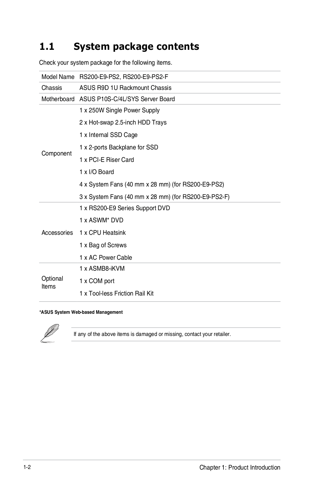
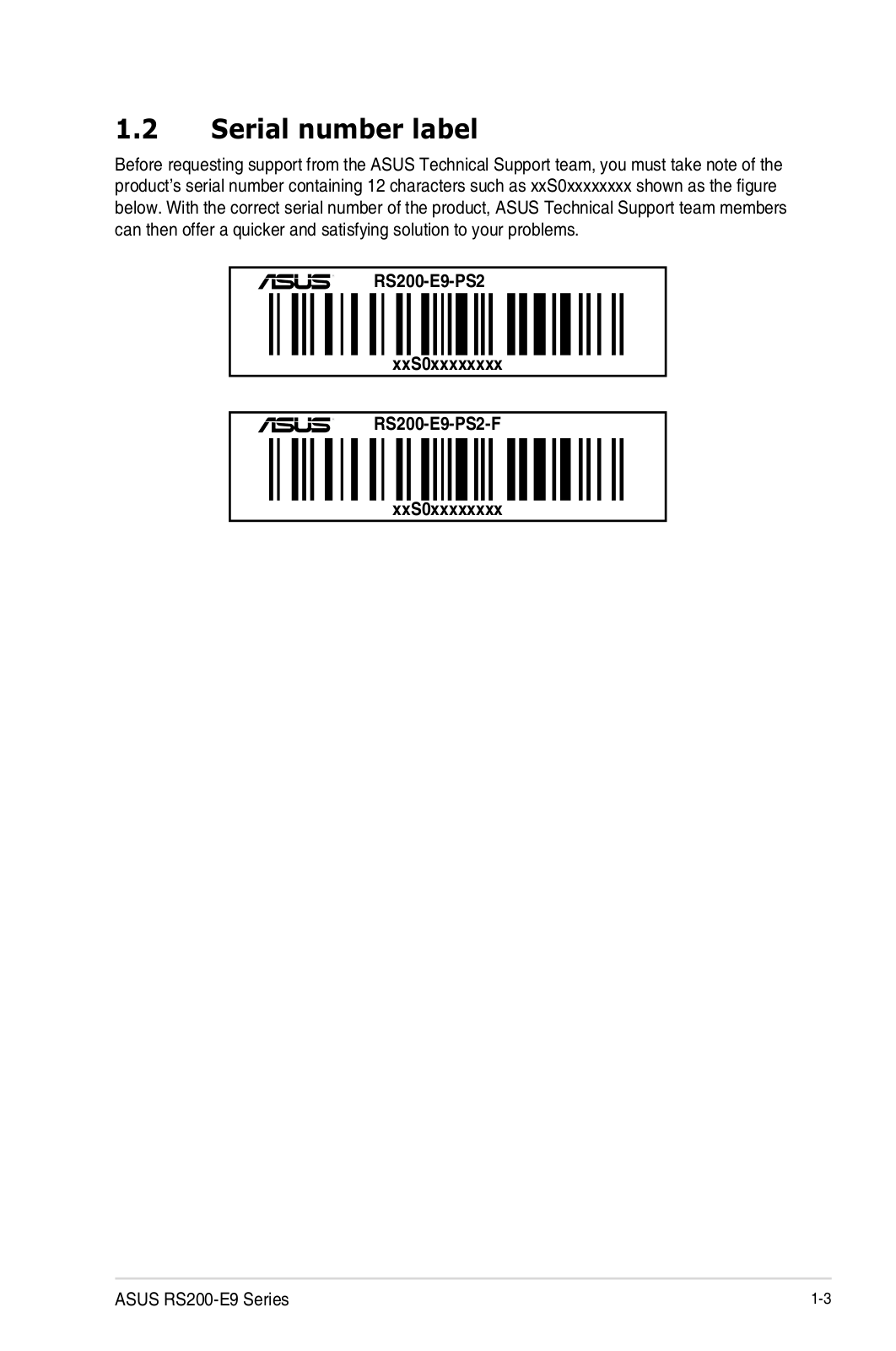
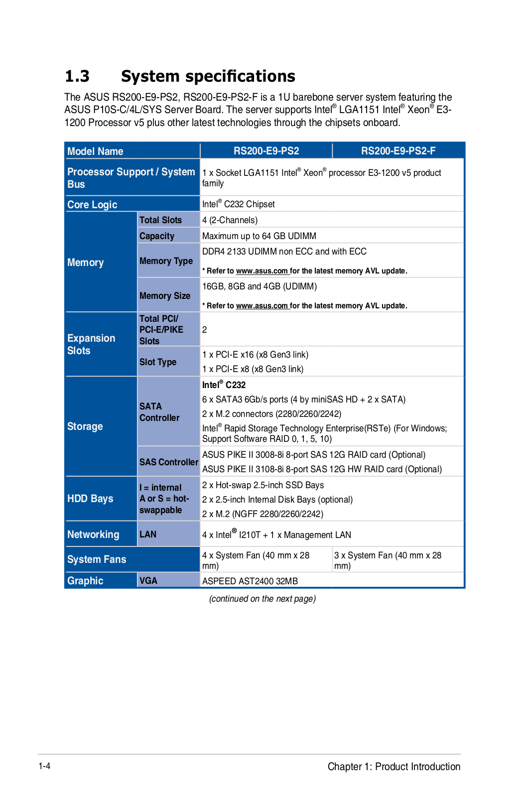
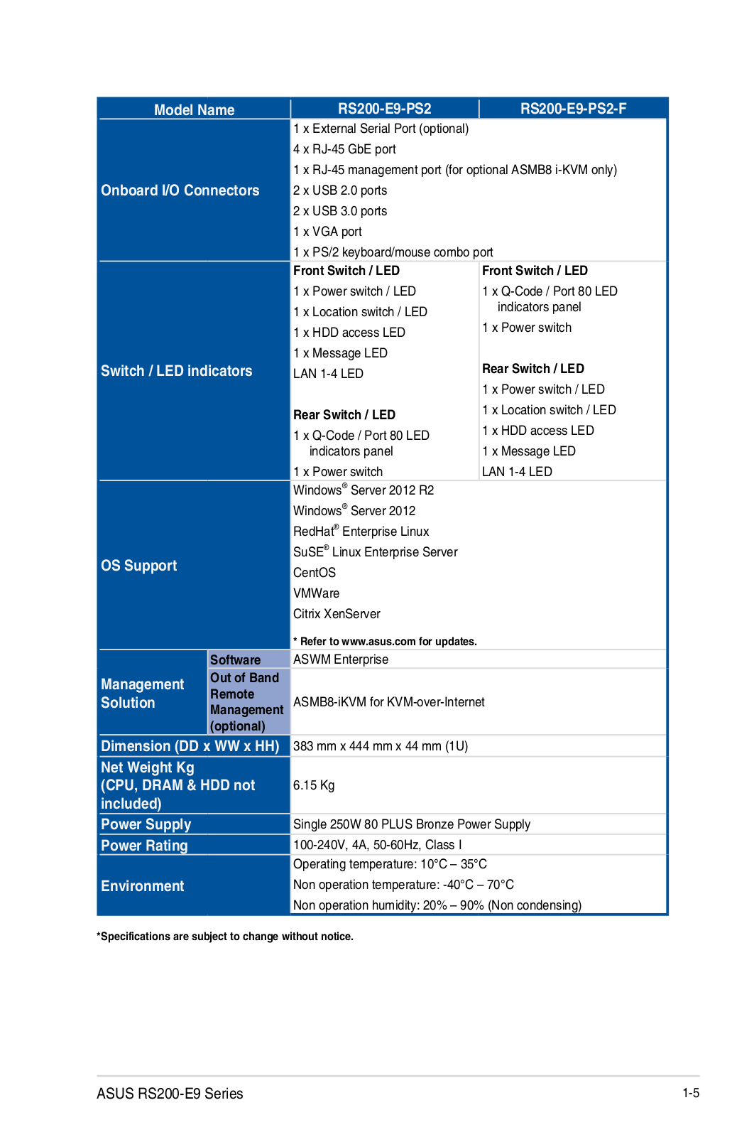
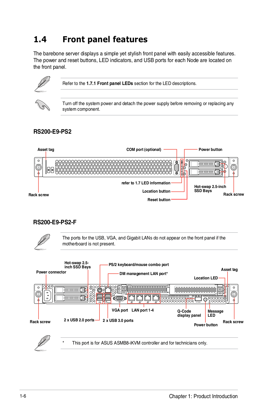
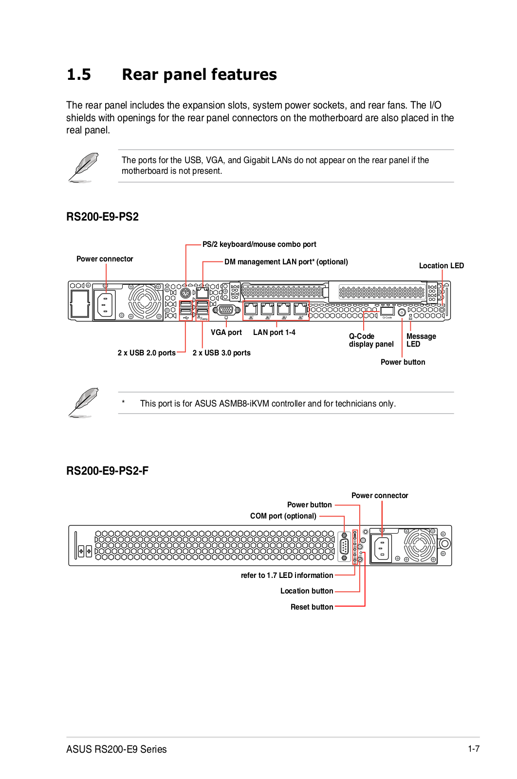
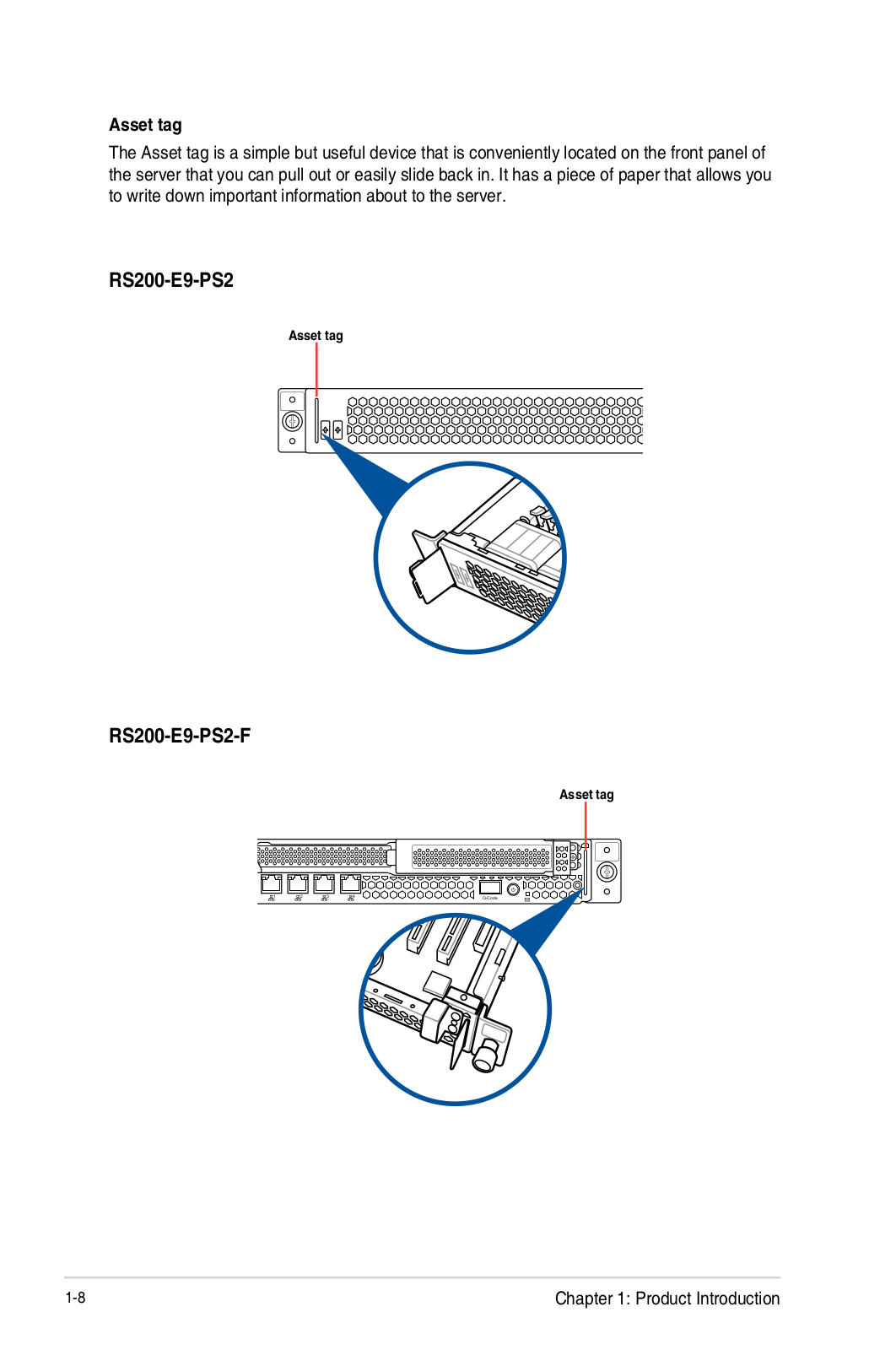
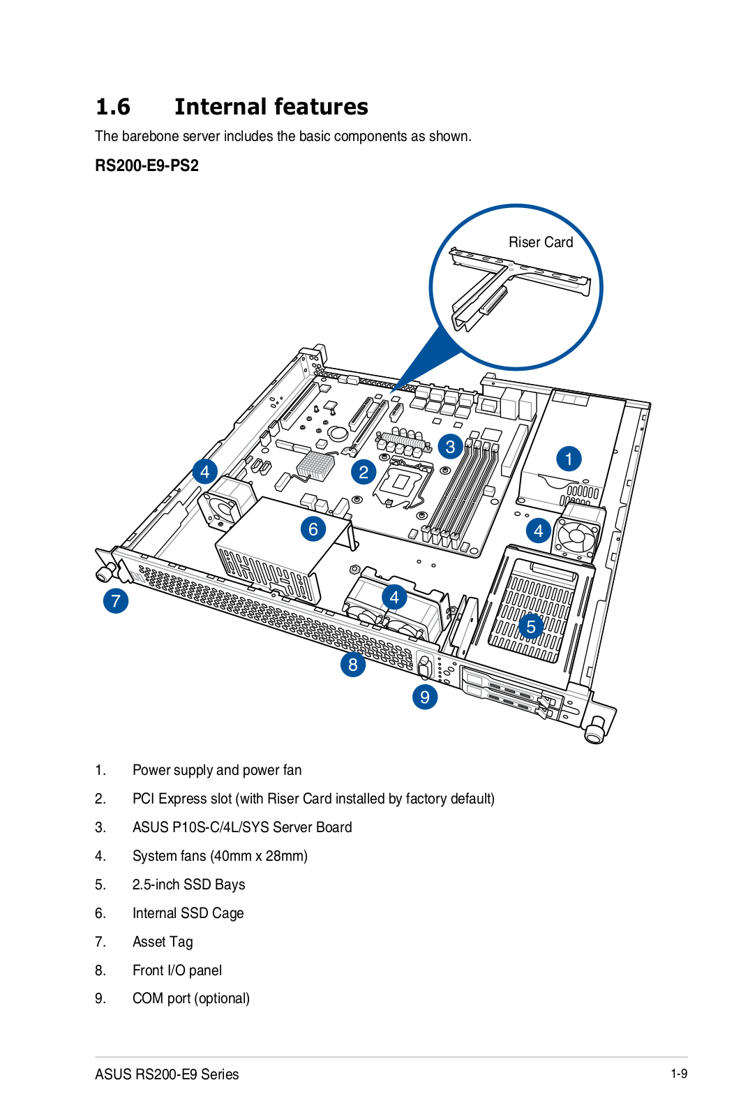
RS200-E9-PS2
2
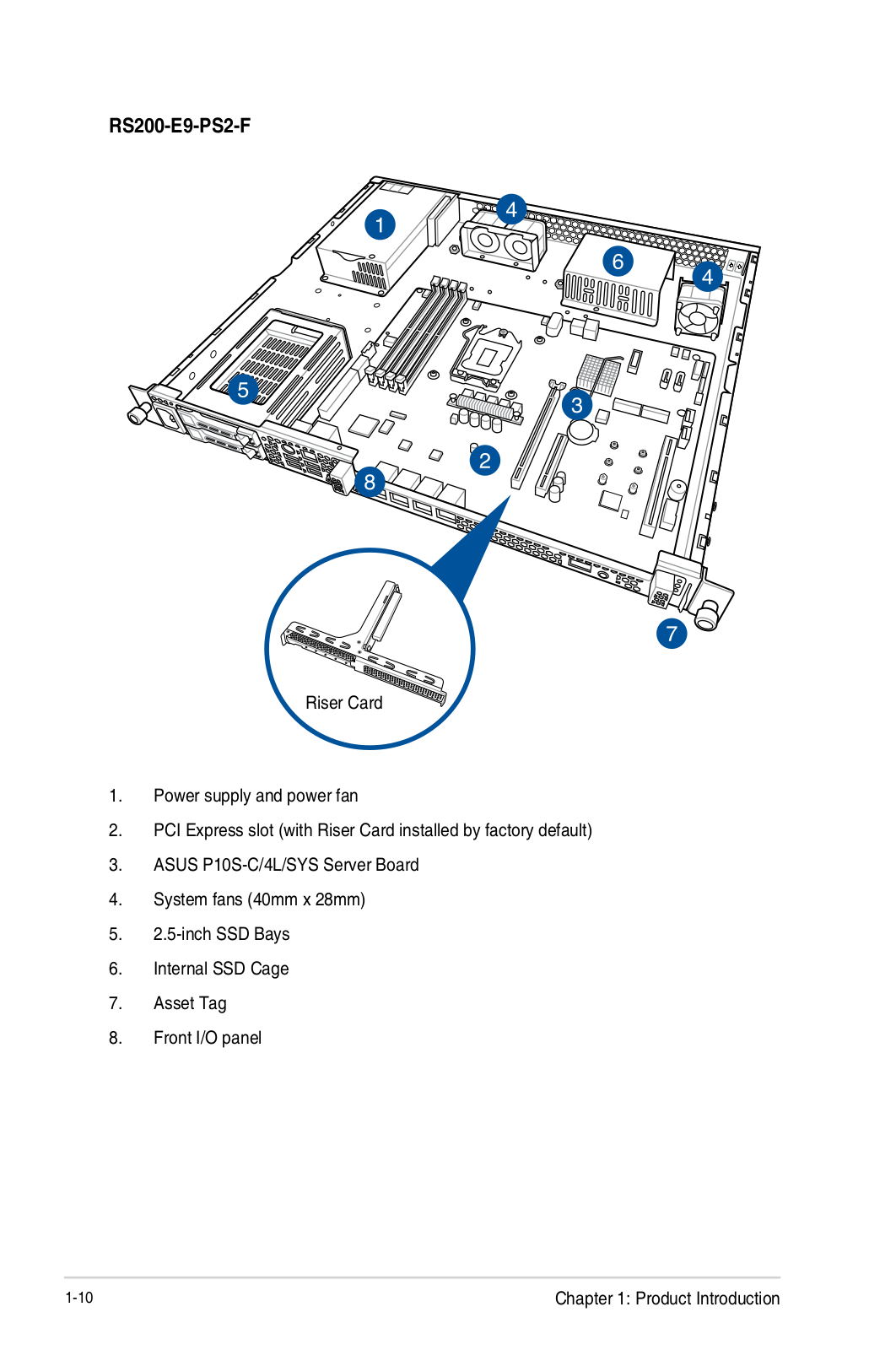
RS200-E9-PS2-F
2
RS260-E3RS8
3
RS260-E4/RX8
3
RS300-E10-PS4
4
RS300-E10-RS4
4
RS300-E6
2
RS300-E6/PS2
3
RS300-E6PS4
2
RS300-E7-PS4
7
RS300-E7/RS4
5
RS300-E8-PS4
4
RS300-E8-RS4
5
RS300-E9-PS4
3
RS300-E9-RS4
4
RS300-H8-PS12
2
RS320Q-E7/RS12
RS400-E8-PS2
2
RS400-E8-PS2-F
2
RS500A-E10-PS4
4
RS500A-E10-RS12U
5
RS500A-E10-RS4
2
RS500A-E6PS4
4
RS500A-E9
RS500A-E9-PS4
2
RS500A-E9-RS4
3
RS500A-E9-RS4-U
3
RS500A-S6/PS4
2
RS500A-X6PS4
2
RS500-E6-EPS4
2
RS500-E6/EPS4 ASWM ENTERPRISE
RS500-E6/PS4
5
RS500-E6-PS8
2
RS500-E7/PS4
2
RS500-E8-PS4
3
RS500-E8-RS4
3
RS500-E8-RS4 V2
RS500-E9
RS500-E9-PS4
4
RS500-E9-RS4
4
RS500-E9-RS4-U
4
RS520-E6/ERS8
2
RS520-E6RS8
4
RS520-E8-RS12-E
8
RS520-E8-RS8
8
RS520-E8-RS8 V2
RS520-E9
RS520-E9-RS12-E
4
RS520-E9-RS8
4
RS520-X5/PS8
3
Loading...
Loading...
Nothing found
RS200-E9-PS2
User Manual
168 pgs
15.85 Mb
0
User’s Manual [zh]
168 pgs
13.36 Mb
0
Table of contents
Loading...
Asus RS200-E9-PS2 User Manual
...
Asus User Manual
Download
Specifications and Main Features
Frequently Asked Questions
User Manual
Download
Loading...
+
138
hidden pages
Unhide
You need points to download manuals.
1 point = 1 manual.
You can buy points or you can get point for every manual you upload.
Buy points
Upload your manuals
 Loading...