


PSCH-SR SATA

PSCH-SR
Series
User Guide
Motherboard

Checklist
E1935
Revised edition V2
January 2005
Copyright © 2005 ASUSTeK COMPUTER INC. All Rights Reserved.
No part of this manual, including the products and software described in it, may be
reproduced, transmitted, transcribed, stored in a retrieval system, or translated into any
language in any form or by any means, except documentation kept by the purchaser for
backup purposes, without the express written permission of ASUSTeK COMPUTER INC.
(“ASUS”).
Product warranty or service will not be extended if: (1) the product is repaired, modified or
altered, unless such repair, modification of alteration is authorized in writing by ASUS; or (2)
the serial number of the product is defaced or missing.
ASUS PROVIDES THIS MANUAL “AS IS” WITHOUT WARRANTY OF ANY KIND, EITHER
EXPRESS OR IMPLIED, INCLUDING BUT NOT LIMITED TO THE IMPLIED WARRANTIES
OR CONDITIONS OF MERCHANTABILITY OR FITNESS FOR A PARTICULAR PURPOSE.
IN NO EVENT SHALL ASUS, ITS DIRECTORS, OFFICERS, EMPLOYEES OR AGENTS BE
LIABLE FOR ANY INDIRECT, SPECIAL, INCIDENTAL, OR CONSEQUENTIAL DAMAGES
(INCLUDING DAMAGES FOR LOSS OF PROFITS, LOSS OF BUSINESS, LOSS OF USE
OR DATA, INTERRUPTION OF BUSINESS AND THE LIKE), EVEN IF ASUS HAS BEEN
ADVISED OF THE POSSIBILITY OF SUCH DAMAGES ARISING FROM ANY DEFECT OR
ERROR IN THIS MANUAL OR PRODUCT.
SPECIFICATIONS AND INFORMATION CONTAINED IN THIS MANUAL ARE FURNISHED
FOR INFORMATIONAL USE ONLY, AND ARE SUBJECT TO CHANGE AT ANY TIME
WITHOUT NOTICE, AND SHOULD NOT BE CONSTRUED AS A COMMITMENT BY ASUS.
ASUS ASSUMES NO RESPONSIBILITY OR LIABILITY FOR ANY ERRORS OR
INACCURACIES THAT MAY APPEAR IN THIS MANUAL, INCLUDING THE PRODUCTS
AND SOFTWARE DESCRIBED IN IT.
Products and corporate names appearing in this manual may or may not be registered
trademarks or copyrights of their respective companies, and are used only for identification or
explanation and to the owners’ benefit, without intent to infringe.
ii

Contents
Notices ............................................................................................v
Safety information ..........................................................................vi
About this guide............................................................................. vii
PSCH-SR specifications summary.................................................ix
Chapter 1: Product introduction
1.1 Welcome! ........................................................................... 1-1
1.2 Package contents............................................................... 1-1
1.3 Special features.................................................................. 1-2
Chapter 2: Hardware information
2.1 Before you proceed ............................................................ 2-1
2.2 Motherboard installation ..................................................... 2-2
2.2.1 Placement direction ............................................... 2-2
2.2.2 Screw holes ........................................................... 2-2
2.2.3 Motherboard layouts .............................................. 2-3
2.2.4 Layout contents ..................................................... 2-6
2.3 Central Processing Unit (CPU)........................................... 2-7
2.3.1 Overview ................................................................ 2-7
2.3.2 Installing the CPU .................................................. 2-7
2.3.3 Installing the optional CPU heatsink
and thermal plate ................................................... 2-9
Features
2.4 System memory ................................................................2-11
2.4.1 Overview ...............................................................2-11
2.4.2 Memory configurations .........................................2-11
2.4.3 Installing a DIMM ................................................. 2-13
2.4.4 Removing a DIMM ............................................... 2-13
2.5 Expansion slots ................................................................ 2-14
2.5.1 Installing an expansion card ................................ 2-14
2.5.2 Configuring an expansion card ............................ 2-14
2.5.3 PCI slots .............................................................. 2-16
2.6 Jumpers............................................................................ 2-17
2.7 Connectors ....................................................................... 2-22
2.7.1 Rear panel connectors......................................... 2-22
2.7.2 Internal connectors .............................................. 2-23
Chapter 3: Powering up
3.1 Starting up for the first time ................................................ 3-1
3.2 Powering off the computer ................................................. 3-2
3.3.1 Using the OS shut down function .......................... 3-2
3.3.2 Using the dual function power switch .................... 3-2
iii

Safeguards
Contents
Chapter 4: BIOS setup
4.1 Managing and updating your BIOS .................................... 4-1
4.1.1 Creating a bootable floppy disk ............................. 4-1
4.1.2 Updating the BIOS ................................................. 4-2
4.1.3 Saving the current BIOS file .................................. 4-4
4.2 BIOS Setup program .......................................................... 4-6
4.2.1 BIOS menu screen ................................................ 4-7
4.2.2 Menu bar................................................................ 4-7
4.2.3 Navigation keys ..................................................... 4-8
4.2.4 General help .......................................................... 4-8
4.2.5 Sub-menu .............................................................. 4-8
4.2.6 Scroll bar................................................................ 4-8
4.2.7 Pop-up window ...................................................... 4-8
4.3 Main menu.......................................................................... 4-9
4.3.1 Primary IDE Master ............................................. 4-10
4.3.2 Primary IDE Slave ............................................... 4-13
4.3.3 Secondary IDE Master......................................... 4-13
4.3.4 Secondary IDE Slave........................................... 4-13
4.4 Advanced menu ............................................................... 4-14
4.4.1 Advanced BIOS Features .................................... 4-15
4.4.2 CPU Configuration ............................................... 4-16
4.4.3 Memory Configuration ......................................... 4-17
4.4.4 Chipset................................................................. 4-18
4.4.5 Onboard Device ................................................... 4-20
4.4.6 PCIPnP ................................................................ 4-24
4.4.7 USB Configuration ............................................... 4-26
4.5 Power menu ..................................................................... 4-27
4.5.1 APM Configuration............................................... 4-27
4.5.2 Hardware Monitor ................................................ 4-31
4.6 Boot menu ........................................................................ 4-33
4.6.1 Boot Device Priority ............................................. 4-33
4.6.2 Hard Disk Boot Priority ........................................ 4-34
4.6.3 Removable Device Priority .................................. 4-34
4.6.4 CD-ROM Boot Priority ......................................... 4-35
4.6.5 Boot Settings Configuration ................................. 4-35
4.6.6 Security ................................................................ 4-37
4.7 Exit menu ......................................................................... 4-39
Appendix: Reference information
A.1 PSCH-SR block diagrams .................................................. A-1
iv

Notices
Federal Communications Commission Statement
This device complies with Part 15 of the FCC Rules. Operation is subject to
the following two conditions:
• This device may not cause harmful interference, and
• This device must accept any interference received including interference
that may cause undesired operation.
This equipment has been tested and found to comply with the limits for a
Class B digital device, pursuant to Part 15 of the FCC Rules. These limits
are designed to provide reasonable protection against harmful interference
in a residential installation. This equipment generates, uses and can radiate
radio frequency energy and, if not installed and used in accordance with
manufacturer’s instructions, may cause harmful interference to radio
communications. However, there is no guarantee that interference will not
occur in a particular installation. If this equipment does cause harmful
interference to radio or television reception, which can be determined by
turning the equipment off and on, the user is encouraged to try to correct the
interference by one or more of the following measures:
• Reorient or relocate the receiving antenna.
• Increase the separation between the equipment and receiver.
• Connect the equipment to an outlet on a circuit different from that to
which the receiver is connected.
• Consult the dealer or an experienced radio/TV technician for help.
The use of shielded cables for connection of the monitor to the
graphics card is required to assure compliance with FCC regulations.
Changes or modifications to this unit not expressly approved by the
party responsible for compliance could void the user’s authority to
operate this equipment.
Canadian Department of Communications Statement
This digital apparatus does not exceed the Class B limits for radio noise
emissions from digital apparatus set out in the Radio Interference
Regulations of the Canadian Department of Communications.
This class B digital apparatus complies with Canadian ICES-003.
v

Safety information
Electrical safety
• To prevent electrical shock hazard, disconnect the power cable from
the electrical outlet before relocating the system.
• When adding or removing devices to or from the system, ensure that
the power cables for the devices are unplugged before the signal
cables are connected. If possible, disconnect all power cables from the
existing system before you add a device.
• Before connecting or removing signal cables from the motherboard,
ensure that all power cables are unplugged.
• Seek professional assistance before using an adapter or extension
cord. These devices could interrupt the grounding circuit.
• Make sure that your power supply is set to the correct voltage in your
area. If you are not sure about the voltage of the electrical outlet you
are using, contact your local power company.
• If the power supply is broken, do not try to fix it by yourself. Contact a
qualified service technician or your retailer.
Operation safety
• Before installing the motherboard and adding devices on it, carefully
read all the manuals that came with the package.
• Before using the product, make sure all cables are correctly connected
and the power cables are not damaged. If you detect any damage,
contact your dealer immediately.
• To avoid short circuits, keep paper clips, screws, and staples away from
connectors, slots, sockets and circuitry.
• Avoid dust, humidity , and temperature extremes. Do not place the
product in any area where it may become wet.
• Place the product on a stable surface.
• If you encounter technical problems with the product, contact a
qualified service technician or your retailer.
vi

About this guide
This user guide contains the information you need when installing and
configuring the motherboard.
How this guide is organized
This user guide contains the following parts:
• Chapter 1: Product introduction
This chapter describes the features of the motherboard. It includes
brief descriptions of the special attributes of the motherboard and the
new technology it supports.
• Chapter 2: Hardware installation
This chapter lists the hardware setup procedures that you have to
perform when installing system components. It includes description of
the switches, jumpers, and connectors on the motherboard.
• Chapter 3: Powering up
This chapter describes the power up sequence and gives information
on the BIOS beep codes.
• Chapter 4: BIOS setup
This chapter tells how to change system settings through the BIOS
Setup menus. Detailed descriptions of the BIOS parameters are also
provided.
• Appendix: Reference information
This appendix includes additional information that you may refer to
when confiiguring the motherboard.
vii

Conventions used in this guide
To make sure that you perform certain tasks properly, take note of the
following symbols used throughout this manual.
WARNING: Information to prevent injury to yourself when trying
to complete a task.
CAUTION: Information to prevent damage to the components
when trying to complete a task.
IMPORTANT: Information that you MUST follow to complete a
task.
NOTE: Tips and additional information to aid in completing a task.
Where to find more information
Refer to the following sources for additional information and for product
and software updates.
1. ASUS websites
The ASUS websites worldwide provide updated information on ASUS
hardware and software products. Refer to the ASUS contact
information.
2. Optional documentation
Your product package may include optional documentation, such as
warranty flyers, that may have been added by your dealer. These
documents are not part of the standard package.
viii

PSCH-SR Series specifications summary
CPU
Chipset
Front Side Bus (FSB)
Memory
Expansion slots
Storage
Socket 478 for Intel® Pentium™ 4 Prescott processors with
Hyper-Threading Technology
On-die 1MB/512KB L2 cache
®
Northbridge: Intel
E7210 Memory Controller Hub (MCH)
Southbridge: Intel® 6300ESB I/O Controller Hub (ICH)
800/533/400 MHz
Dual-channel memory architecture
4 x 184-pin DDR DIMM sockets for up to 4 GB memory
supports PC3200/PC2700/PC2100 unbuffered ECC or
non-ECC DDR DIMMs
1 x 3.3 V/64-bit/66 MHz PCI-X with Zero Channel RAID
(ZCR) support
2 x 5 V/32-bit/33 MHz PCI
IDE model
®
6300ESB I/O Controller Hub (ICH) supports:
Intel
- 2 x IDE connectors (dual-channel bus master IDE
for up to four UltraAT A100/66/33 hard disk drives
- 2 x Serial ATA connectors (for RAID 0 and RAID 1
configurations using two SATA hard disk drives and
Windows® XP)
Graphics
LAN
ASUS unique features
Serial A TA model
IDE model storage + Adaptec® AIC-81 10X support:
- 4 x Serial ATA connectors (for RAID 0, RAID 1,
RAID 0+1, and RAID 5 configurations using four SATA
hard disk drives and the optional Adaptec® SODIMM
Zero Channel RAID card)
SCSI model
IDE model storage + Adaptec® AIC-7901X support:
- Single channel Ultra320 SCSI connector (for RAID 0,
RAID 1, RAID 0+1, and RAID 5 configurations using
SCSI hard disk drives and the optional Adaptec
®
SODIMM Zero Channel RAID card)
ATI Rage™ XL PCI graphics controller with 8 MB VRAM
®
82547GI CSA Gigabit LAN controller
Intel
Intel® 82541GI Gigabit LAN controller (32-bit)
ASUS Q-Fan Technology
ASUS Update
(continued on the next page)
ix
PSCH-SR Series specifications summary
Rear panel ports
Internal connectors
BIOS features
1 x Serial (COM1) port
2 x LAN (RJ-45) ports
1 x PS/2 keyboard port
1 x PS/2 mouse port
2 x USB 2.0 ports
1 x VGA port
CPU/system/chassis fan connectors
20-pin ATX and 4-pin ATX 12V power connectors
20-pin front panel connectors
USB 2.0/1.1 connector
Chassis intrusion connector
Serial port (COM2) connector (for server management use only)
Baseboard Management Connector (BMC) for server
management card
SODIMM slot for Adaptec
SCSI/SATA models only)
68-pin Ultra320 SCSI connector (SCSI models only)
4 x horizontal Serial ATA connectors (SATA models only)
Firmware Hub Flash ROM (4 Mb for IDE models; 8 Mb for
SCSI and SATA models), Award BIOS with enhanced ACPI,
PnP, DMI2.0, Green
®
Zero Channel RAID card (optional on
Industry standard
Manageability
Power requirement
Form Factor
Support CD contents
*Specifications are subject to change without notice.
PCI 2.2, PCI-X 1.0a, USB 2.0
WfM 2.0. DMI 2.0, WOL/WOR by PME, chassis intrusion
ATX power supply (with 4-pin 12V plug)
ATX form factor: 12in x 9.8in (30.5 cm x 25 cm)
Device drivers
Management software
System utilities
ASUS contact information
x

Chapter 1
This chapter describes the features of the
motherboard. It includes brief descriptions
of the special attributes of the motherboard
and the new technology it supports.
Product introduction

Chapter summary
1.1 Welcome! ........................................................ 1-1
1.2 Package contents .......................................... 1-1
1.3 Special features ............................................. 1-2
ASUS PSCH-SR motherboard
1.1 Welcome!
Thank you for buying the ASUS® PSCH-SR series motherboard!
The ASUS
and latest technologies making it another standout in the long line of
ASUS quality motherboards!
The motherboard incorporates the Intel
package coupled with the Intel® E7210/6300ESB chipset to provide a
powerful server/workstation platform solution.
Supporting 800 MHz FSB, up to 4 GB of system memory with
dual-channel PC3200/2700/2100 DDR SDRAM, high-resolution graphics
through an onboard VGA, Serial ATA support, dual Gigabit LAN, PCI-X,
and USB 2.0 interfaces, PSCH-SR is your perfect vehicle to get ahead in
the world of power computing!
Before you start installing the motherboard, and hardware devices on it,
check the items in your package with the list below.
PSCH-SR series motherboard delivers a host of new features
®
Pentium™ 4 processor in 478-pin
1.2 Package contents
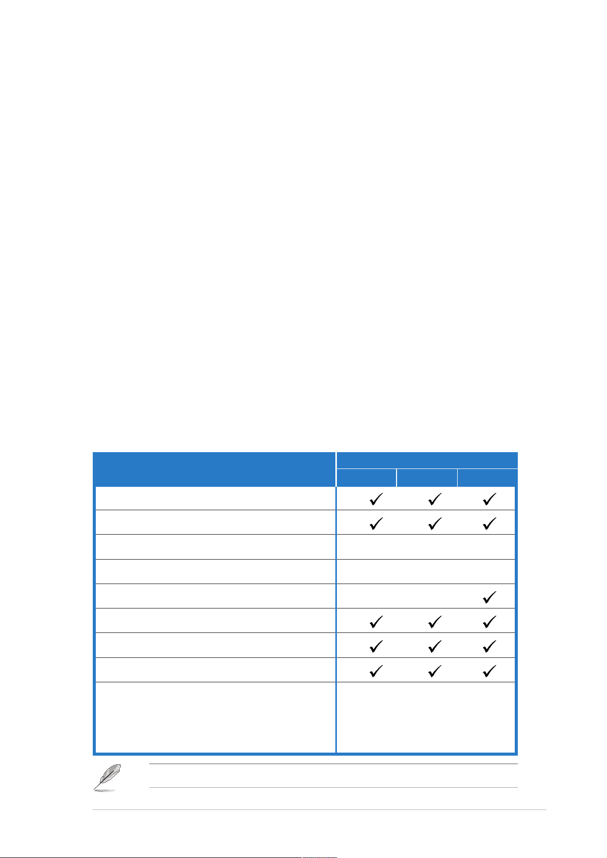
Check your PSCH-SR package for the following items.
PSCH-SR models
Item Description
ASUS PSCH-SR motherboard
ASUS PSCH-SR support CD
SATA cables 2 6 2
SATA power cables 1 3 1
SCSI cable ••
4-in-1 IDE/FDD cable set
I/O shield
User guide
Optional items:
CPU heatsink and thermal plate
®
Adaptec
Zero Channel RAID card
IDE SATA SCSI
Contact your retailer if any of the above items is damaged or missing.
ASUS PSCH-SR motherboard user guide
1-1

1.3 Special features
1.3.1 Product highlights
Latest processor technology
The motherboard supports the latest Intel® Pentium™ 4 processor via a
478-pin surface mount ZIF socket. The processor with 1 MB/512 KB L2
cache includes a 800/533/400 MHz system bus and features the Intel
Hyper-Threading Technology and new power design that allow up to
3.4+ GHz core frequencies. The motherboard fully supports the new
generation 90 nm Pentium® 4 processor.
Dual-channel DDR400 memory support
Employing the dual-channel DDR memory architecture, the motherboard
provides a solution that doubles the system memory bandwidth to boost
system performance. The motherboard supports up to 4 GB of system
memory using PC3200/2700/2100 ECC or non-ECC DDR DIMMs to
deliver up to 6.4 GB/s data transfer rate for various server applications.
Serial ATA technology
The motherboard supports the new Serial ATA technology through the
SATA interfaces and the Intel® 6300ESB. The SATA specification allows for
thinner, more flexible cables with lower pin count, reduced voltage
requirement, and up to 150 MB/s data transfer rate. For Serial ATA
models, the Adaptec® AIC-8110X chip supports four additional SATA
connectors to give you six fully-compatible SATA interfaces. For IDE
models, the Intel® 6300ESB ICH provides RAID 0 and RAID 1 solution for
two Serial ATA interfaces using the Windows® XP operating system.
Zero Channel RAID (ZCR) solution (optional on SA TA and SCSI
models only)
The motherboard supports the optional Zero Channel RAID card in
SODIMM package for a multi-RAID solution using Serial ATA150 hard disk
drives or Ultra320 SCSI hard disk drives. The RAID 0 (striping), RAID 1
(mirroring), RAID 0+1, and RAID 5 provide a cost-effective, reliable and
high-performance server system.
1-2
Chapter 1: Product introduction

Single-channel Ultra320 SCSI support (on SCSI models only)
The Adaptec® AIC-7901X Ultra320 SCSI controller and single-channel
SCSI connector are onboard to provide high-speed data transfers to and
from SCSI hard disk drives.
Integrated graphics
The onboard ATI Rage™ XL graphics controller with 8 MB memory
provides a reliable solution for server applications.
USB 2.0 technology
The motherboard implements the Universal Serial Bus (USB) 2.0
specification, dramatically increasing the connection speed from the
12Mbps bandwidth on USB 1.1 to a fast 480 Mbps on USB 2.0. USB 2.0
is backward compatible with USB 1.1.
Dual Gigabit LAN solution
The Intel® 82541GI and Intel® 82547GI Gigabit Ethernet controller allows
full-duplex Gigabit performance on LAN on Motherboard (LOM)
applications. Take the advantage of the Communication Streaming
Architecture (CSA) with the Intel® 82547GI controller that connects to the
dedicated CSA bus on the Memory Controller Hub (MCH). This reduces
the PCI bottlenecks by freeing the PCI bus for other I/O operations. The
Intel® 82541GI controller utilizes the PCI interface on the Southbridge to
provide a faster and more efficient networking performance.
Server management
With the onboard Baseboard Management Connector (BMC) for the ASUS
server management card, managing your server motherboard has never
been this easy. ASUS server management cards fully conform to the
IPMI1.5 or 2.0 versions.
Chassis intrusion detection
The motherboard supports chassis intrusion monitoring through the Winbond
ASIC. A chassis intrusion event is retained in the CMOS for added protection.
ASUS PSCH-SR motherboard user guide
1-3

1.3.2 ASUS unique features
ASUS Q-Fan technology
The ASUS Q-Fan technology smartly adjusts the fan speeds according to
the system loading to ensure quiet, cool, and efficient operation.
ASUS Update
This utility allows you to update the motherboard BIOS through a userfriendly interface. Connect to the Internet then to the ASUS FTP site
nearest you to obtain the latest BIOS version for your motherboard.
1-4
Chapter 1: Product introduction

Chapter 2
This chapter describes the hardware
setup procedures that you have to
perform when installing system
components. It includes details on
the switches, jumpers, and
connectors on the motherboard.
Hardware information

Chapter summary
2.1 Before you proceed ....................................... 2-1
2.2 Motherboard installation ............................... 2-2
2.3 Central Processing Unit (CPU) ..................... 2-7
2.4 System memory ............................................2-11
2.5 Expansion slots ........................................... 2-14
2.6 Jumpers ........................................................ 2-17
2.7 Connectors ................................................... 2-22
ASUS PSCH-SR motherboard
2.1 Before you proceed
Take note of the following precautions before you install motherboard
components or change any motherboard settings.
1. Unplug the power cord from the wall socket before touching any
component.
2. Use a grounded wrist strap or touch a safely grounded object or to
a metal object, such as the power supply case, before handling
components to avoid damaging them due to static electricity.
3. Hold components by the edges to avoid touching the ICs on them.
4. Whenever you uninstall any component, place it on a grounded
antistatic pad or in the bag that came with the component.
5. Before you install or remove any component, ensure that the
ATX power supply is switched off or the power cord is
detached from the power supply. Failure to do so may cause
severe damage to the motherboard, peripherals, and/or
components.
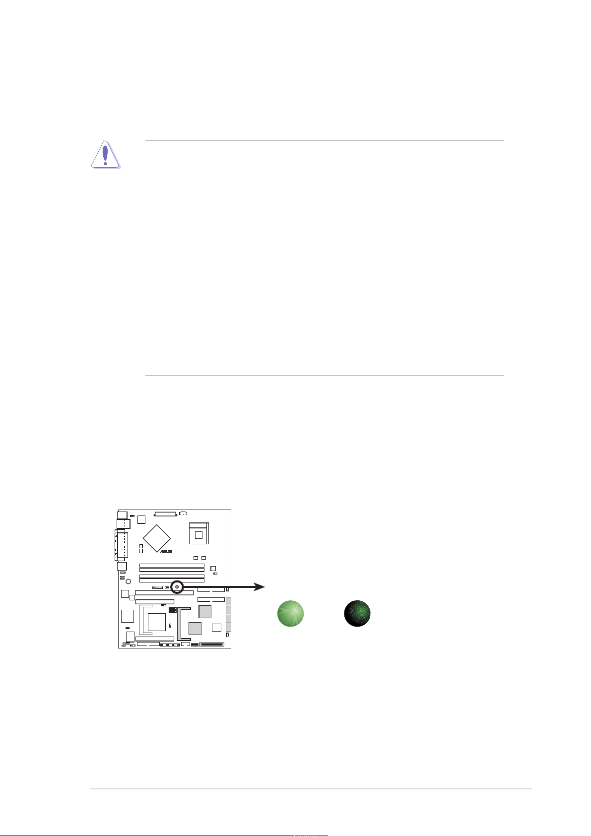
Power LED
The motherboard has a green power LED (SB_PWR1). When lit, this LED
indicates that the system is ON, in sleep mode, or in soft-off mode, a
reminder that you should shut down the system and unplug the power
cable before removing or plugging in any motherboard component.
®
PSCH-SR
SB_PWR1
PSCH-SR Onboard LED
ON
Standby
Power
OFF
Powered
Off
ASUS PSCH-SR motherboard
2-1
2.2 Motherboard installation
Before you install the motherboard, study the configuration of your chassis
to ensure that the motherboard fits into it.
Make sure to unplug the power cord before installing or removing the
motherboard. Failure to do so may cause you physical injury and
damage motherboard components.
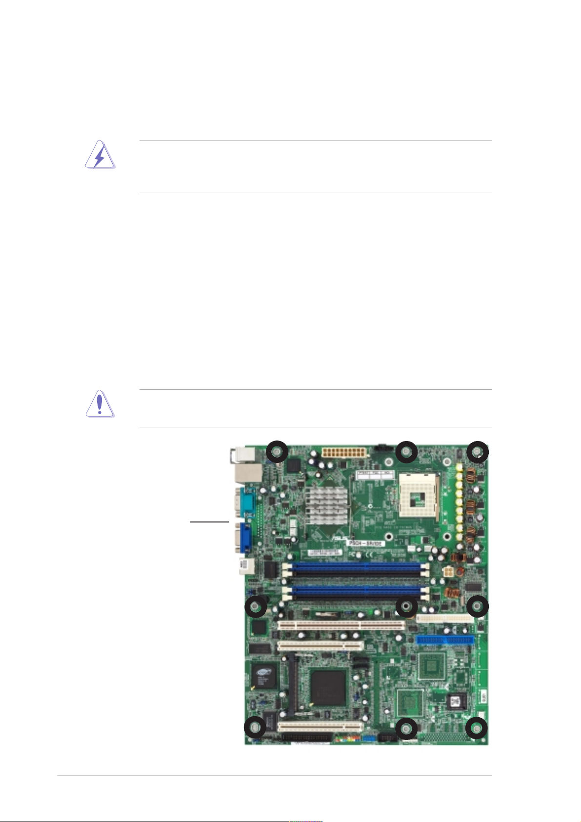
2.2.1 Placement direction
When installing the motherboard, make sure that you place it to the
chassis in the correct orientation. The edge with external ports goes to the
rear part of the chassis as indicated in the image below.
2.2.2 Screw holes
Secure the motherboard to the chassis with nine (9) screws on the holes
indicated by the circles.
Do not overtighten the screws! Doing so may damage the
motherboard.
Place this side towards
the rear of the chassis
2-2
Chapter 2: Hardware information
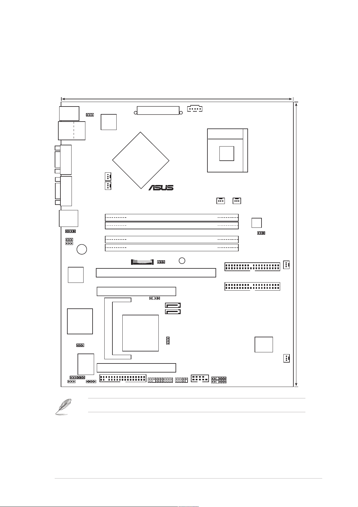
2.2.3 Motherboard layouts
IDE model
25cm (9.8in)
PS/2KBMS
T: Mouse
B: Keyboard
USB2.0
T: USB1
B: USB2
COM1
VGA
LAN2
LAN_EN1
LAN_EN2
82541GI
Ethernet
Top:
LAN1
LAN_LED1
BUZZER1
Intel
Gigabit
KBPWR1
REAR_FAN1
REAR_FAN2
Intel
82547GI
Gigabit
Ethernet
Intel
ATXPWR1
®
PSUSMB1
E7210
MCH
®
PSCH-SR
DDR DIMM_A1 (64 bit,184-pin module)
DDR DIMM_A2 (64 bit,184-pin module)
DDR DIMM_B1 (64 bit,184-pin module)
DDR DIMM_B2 (64 bit,184-pin module)
BAT1
PCIX1
(64-bit, 66MHz 3V)
CLRTC1
SB_PWR1
Socket 478
SEC_IDE1
PRI_IDE1
CPU_FAN2CPU_FAN1
ATX12V1
J6
FRONT_FAN1
30.5cm (12in)
RAGE XL
Controller
LOCATOR1
PCI2 (32-bit, 33MHz 5V)
CHASSIS1
SATA2
ATI
VGA
Intel
SATA1
®
6300ESB
ICH
FLOPPY1
SASI_EN1
PANEL1
USB34
COM2
BPSMB1
FPSMB1
BIOS
4Mbit
Flash
FRONT_FAN2
VGA_EN1
I/O
Super
J4J5
BMCSOCKET1
PCI3 (32-bit, 33MHz 5V)
The BMCSOCKET1 slot is reserved for a server management card.
ASUS PSCH-SR motherboard
2-3
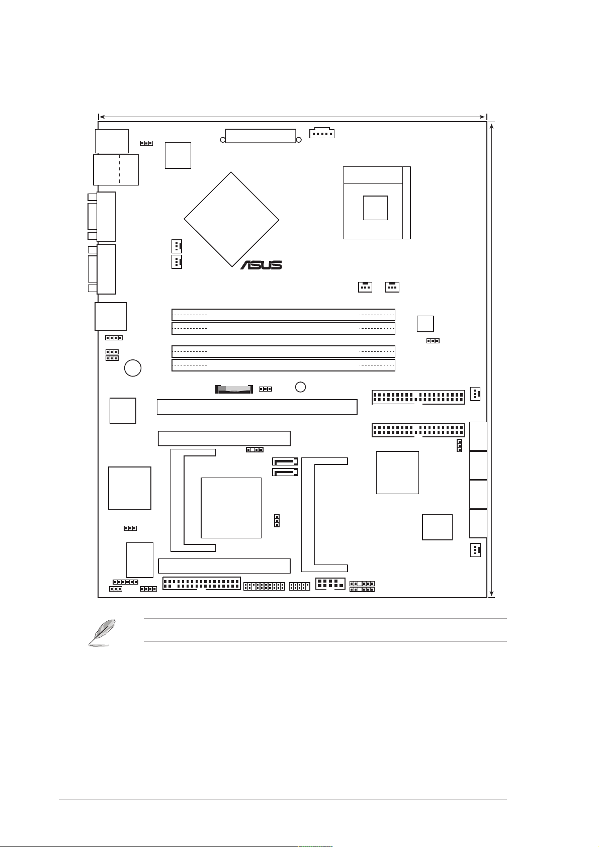
SATA model
25cm (9.8in)
PS/2KBMS
T: Mouse
B: Keyboard
USB2.0
T: USB1
B: USB2
COM1
VGA
LAN2
LAN_EN1
LAN_EN2
82541GI
Gigabit
Ethernet
Top:
LAN1
REAR_FAN2
LAN_LED1
BUZZER1
Intel
KBPWR1
REAR_FAN1
Intel
82547GI
Gigabit
Ethernet
Intel
ATXPWR1
®
PSUSMB1
E7210
MCH
®
PSCH-SR
DDR DIMM_A1 (64 bit,184-pin module)
DDR DIMM_A2 (64 bit,184-pin module)
DDR DIMM_B1 (64 bit,184-pin module)
DDR DIMM_B2 (64 bit,184-pin module)
BAT1
PCIX1
(64-bit, 66MHz 3V)
CLRTC1
SB_PWR1
Socket 478
SEC_IDE1
PRI_IDE1
CPU_FAN2CPU_FAN1
ATX12V1
J6
FRONT_FAN1
30.5cm (12in)
RAGE XL
Controller
LOCATOR1
PCI2 (32-bit, 33MHz 5V)
ATI
VGA
Intel
CHASSIS1
SATA2
SATA1
®
Adaptec
AIC-8110X
J2
6300ESB
ICH
FLOPPY1
PANEL1
SASI_EN1
USB34
ZCRSKT1
COM2
BPSMB1
FPSMB1
BIOS
8Mbit
Flash
FRONT_FAN2
VGA_EN1
I/O
Super
J4J5
BMCSOCKET1
PCI3 (32-bit, 33MHz 5V)
The BMCSOCKET1 slot is reserved for a server management card.
SATA_RAID1 SATA_RAID2 SATA_RAID3 SATA_RAID4
2-4
Chapter 2: Hardware information
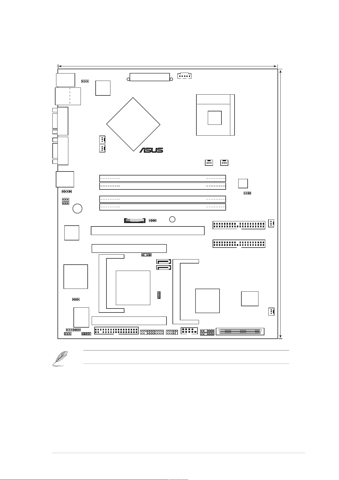
SCSI model
25cm (9.8in)
PS/2KBMS
T: Mouse
B: Keyboard
USB2.0
T: USB1
B: USB2
COM1
VGA
LAN2
LAN_EN1
LAN_EN2
82541GI
Ethernet
Top:
LAN1
LAN_LED1
BUZZER1
Intel
Gigabit
KBPWR1
REAR_FAN1
REAR_FAN2
Intel
82547GI
Gigabit
Ethernet
Intel
ATXPWR1
®
PSUSMB1
E7210
MCH
®
PSCH-SR
DDR DIMM_A1 (64 bit,184-pin module)
DDR DIMM_A2 (64 bit,184-pin module)
DDR DIMM_B1 (64 bit,184-pin module)
DDR DIMM_B2 (64 bit,184-pin module)
BAT1
PCIX1
(64-bit, 66MHz 3V)
CLRTC1
SB_PWR1
Socket 478
SEC_IDE1
PRI_IDE1
CPU_FAN2CPU_FAN1
ATX12V1
J6
FRONT_FAN1
30.5cm (12in)
RAGE XL
Controller
LOCATOR1
PCI2 (32-bit, 33MHz 5V)
CHASSIS1
SATA2
ATI
VGA
Intel
SATA1
®
6300ESB
ICH
FLOPPY1
PANEL1
SASI_EN1
USB34
ZCRSKT1
COM2
Adaptec
AIC-7901X
BPSMB1
FPSMB1
BIOS
8Mbit
Flash
FRONT_FAN2
34 1
SCSIA1
3568
VGA_EN1
I/O
Super
J4J5
BMCSOCKET1
PCI3 (32-bit, 33MHz 5V)
The BMCSOCKET1 slot is reserved for a server management card.
ASUS PSCH-SR motherboard
2-5
2.2.4 Layout contents
Slots Page
1. DDR DIMM 2-11
2. PCI 2-16
Jumpers
1. Keyboard power (3-pin KBPWR1) 2-17
2. Integrated LAN controllers (3-pin LAN_EN1; LAN_EN2) 2-17
3. Integrated graphics controller (3-pin VGA_EN1) 2-18
4. SATA/SCSI jumper controller (3-pin SASI_EN1) 2-18
5. Clear RTC RAM (3-pin CLRTC1) 2-19
6. Force BIOS recovery (3-pin J5) 2-20
7. Hard disk drive/SCSI LED switch (4-pin J4) 2-20
8. DDR voltage regulator (3-pin J6) 2-21
9. Serial ROM initialization jumper (3-pin J2) 2-21
Rear panel connectors
1. PS/2 mouse port 2-22
2. LAN1 port 2-22
3. LAN2 port 2-22
4. VGA port 2-22
5. Serial port 2-22
6. USB 2.0 ports 1 and 2 2-2223
7. PS/2 keyboard port 2-22
Internal connectors
1. Power supply unit SMBus connector (5-pin PSUSMB1) 2-23
2. Front panel SMBus connector (6-1 pin FPSMB1 [white]) 2-23
3. Backplane SMBus connector (6-1 pin BPSMB1 [black]) 2-24
4. Chassis intrusion connector (4-1 pin CHASSIS1) 2-24
5. IDE connectors (40-1 pin PRI_IDE1 [blue], SEC_IDE1 [black) 2-25
6. Serial ATA connectors (7-pin SATA1, SATA2) 2-26
7. Serial ATA RAID connectors (7-pin SATA_RAID1, 2-27
SATA_RAID2, SATA_RAID3, SATA_RAID4)
8. LAN LED connector (4-pin LAN_LED1) 2-27
9. ATX power connectors (20-pin ATXPWR1, 4-pin ATX12V1) 2-28
10. Floppy disk drive connector (34-1 pin FLOPPY1) 2-28
11. Ultra320 SCSI connector (68-pin SCSIA1) 2-29
12. Locator connector (6-pin LOCATOR) 2-29
13. CPU, Front, and Rear Fan connectors 2-30
(3-pin CPU_FAN1/2, FRONT_FAN1/2, REAR_FAN1/2)
14. Serial connector (10-1 pin COM2 for management use) 2-30
15. System panel connector (20-1 pin PANEL) 2-31
2-6
Chapter 2: Hardware information
2.3 Central Processing Unit (CPU)
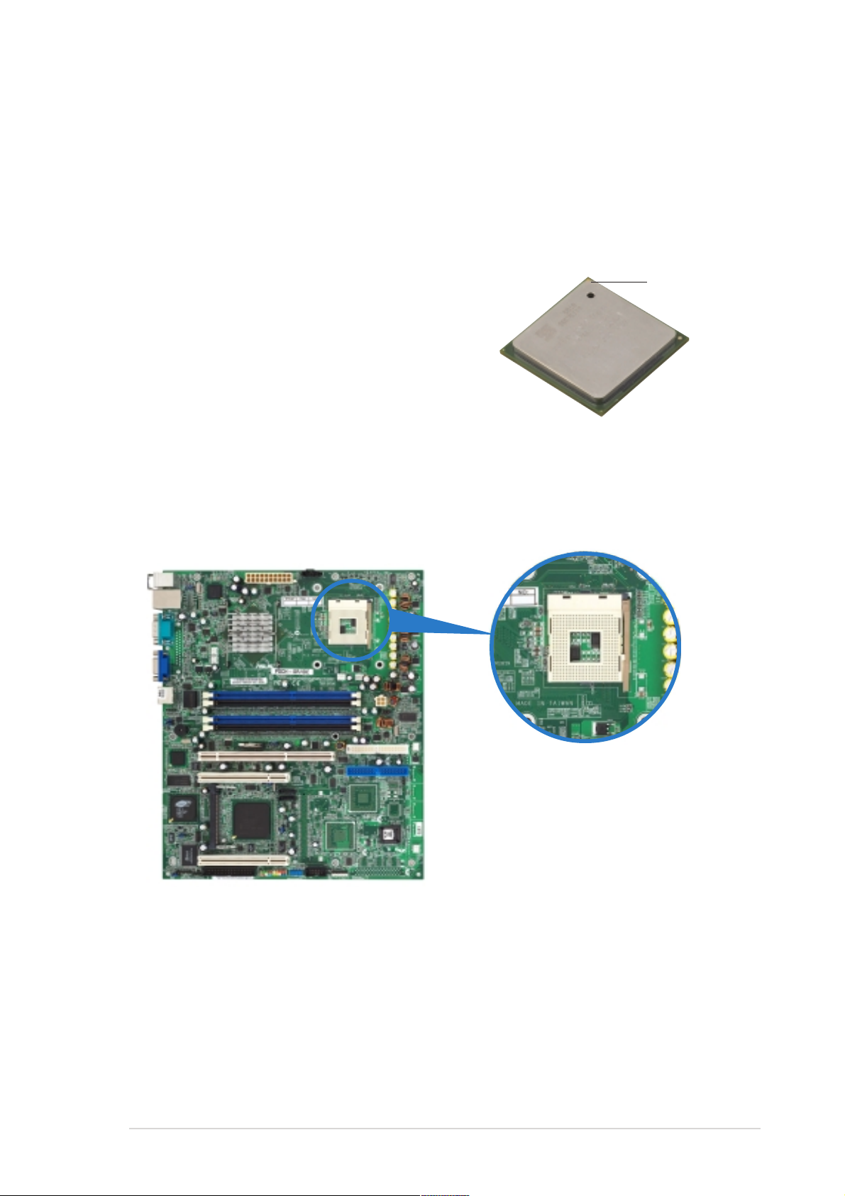
2.3.1 Overview
The motherboard comes with a surface mount 478-pin Zero Insertion
Force (ZIF) socket. The socket is designed for the Intel® Pentium™ 4
processor in the 478-pin package with 1 MB/512 KB L2 cache.
Take note of the marked corner (with gold
triangle) on the CPU. This mark should match
a specific corner of the CPU socket.
2.3.2 Installing the CPU
Follow these steps to install a CPU.
1. Locate the 478-pin ZIF socket on the motherboard.
Gold Mark
ASUS PSCH-SR motherboard
2-7
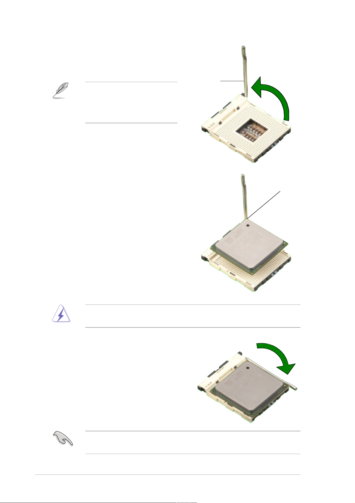
2. Unlock the socket by pressing the
lever sideways, then lift it up to a
90°-100° angle.
Socket Lever
Make sure that the socket
lever is lifted up to 90°-100°
angle; otherwise, the CPU
does not fit in completely.
3. Position the CPU above the
socket such that its marked
corner matches the base of the
socket lever.
4. Carefully insert the CPU into the
socket until it fits in place.
90º ~ 100º angle
Gold Mark
The CPU fits only in one correct orientation. DO NOT force the CPU
into the socket to prevent bending the pins and damaging the CPU!
5. When the CPU is in place, push
down the socket lever to secure
the CPU. The lever clicks on the
side tab to indicate that it is
locked.
After installation, make sure to plug-in the 4-pin ATX power cable to the
motherboard.
2-8
Chapter 2: Hardware information
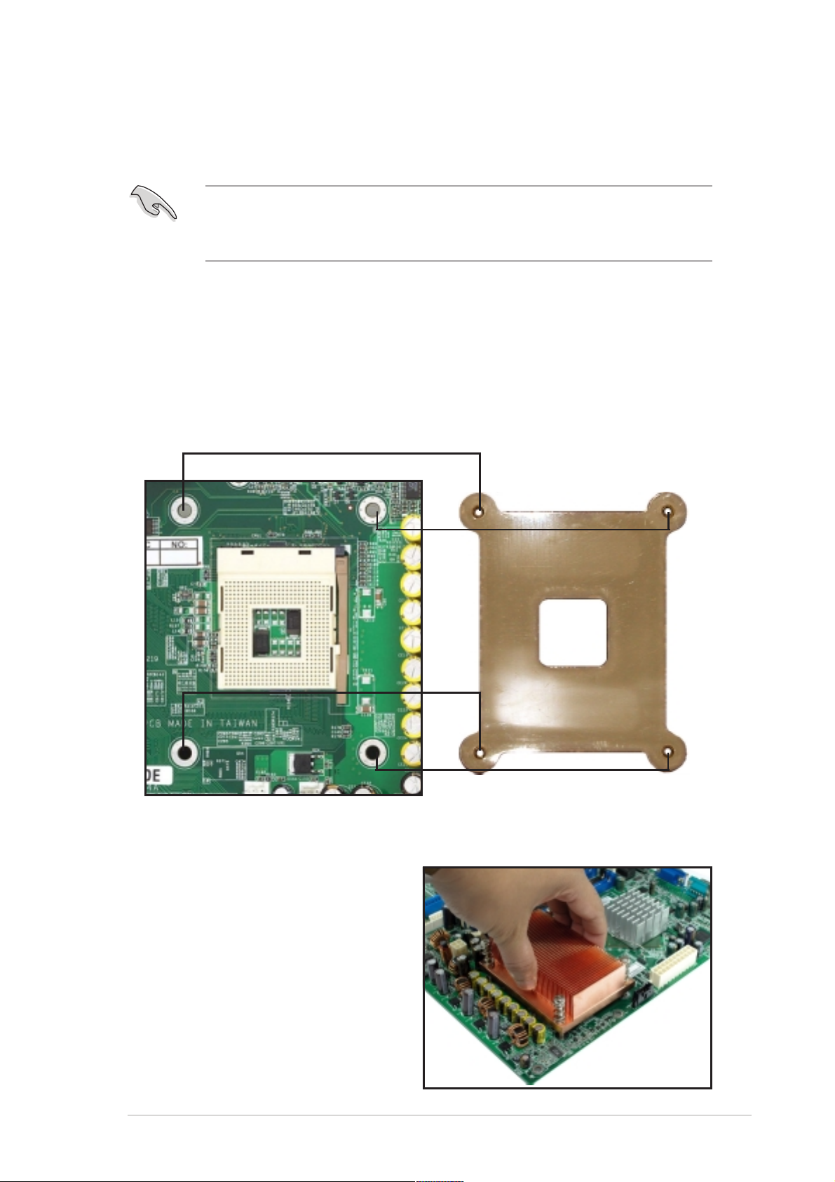
2.3.3 Installing the optional CPU heatsink and
thermal plate
The passive CPU heatsink and a thermal plate is purchased
separately. For optimum thermal solution, use the recommended CPU
heatsink and thermal plate.
CPU thermal plate
This motherboard requires a thermal plate for the CPU. Place the thermal
plate underneath the motherboard before you install the heatsink.
Refer to the picture below for the correct matching of the motherboard and
thermal plate holes.
To install the CPU heatsink:
1. Carefully place the heatsink on
top of the installed CPU.
ASUS PSCH-SR motherboard
2-9
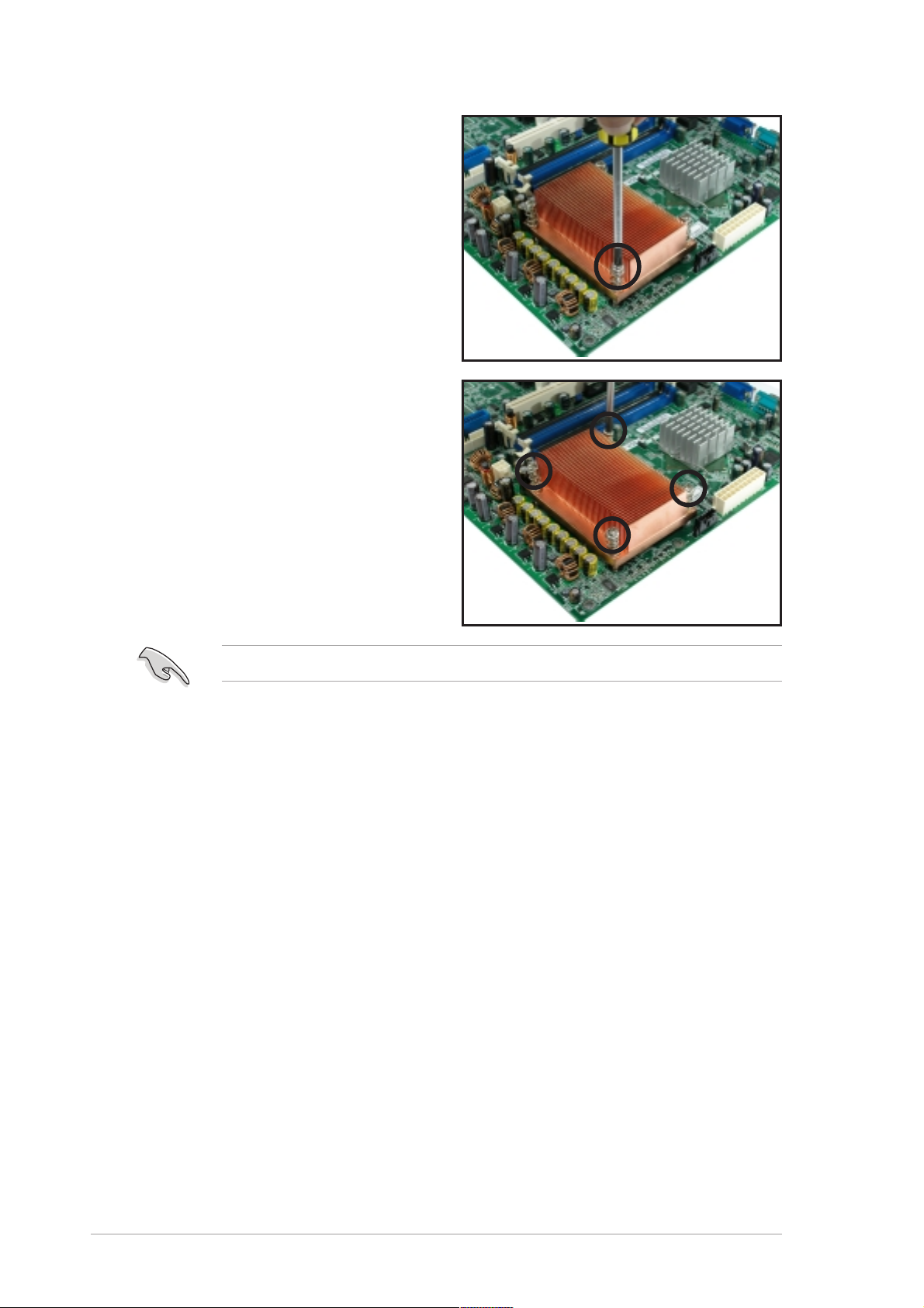
2. Hold down the heatsink lightly
and twist each of the four
screws with a Philips (cross)
screwdriver just enough to
attach the heatsink to the
motherboard.
3. When the four screws are
attached, tighten them one by
one to completely secure the
heatsink.
Do not overtighten the screws to avoid damaging the motherboard.
2-10
Chapter 2: Hardware information
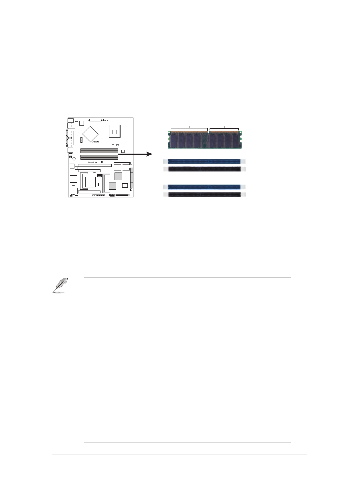
2.4 System memory
2.4.1 Overview
The motherboard comes with four Double Data Rate (DDR) Dual Inline
Memory Module (DIMM) sockets.
The following figure illustrates the location of the sockets.
80 Pins104 Pins
®
PSCH-SR
DIMM_A1
DIMM_A2
DIMM_B1
PSCH-SR 184-Pin DDR DIMM Sockets
DIMM_B2
2.4.2 Memory configurations
You may install 64 MB, 128 MB, 256 MB, 512 MB, and 1GB DDR DIMMs
into the DIMM sockets using the memory configurations in this section.
Important notes on memory configurations
• Installing DDR DIMMs other than the recommended configurations
may cause memory sizing error or system boot failure. Use any of
the recommended configurations in Table 1.
• Use the blue DIMM slots first.
• In Dual-channel configurations, install only identical (the same type
and size) DDR DIMM pairs for each channel.
• Always install DIMMs with the same CAS latency, otherwise, the
system may run in a lower frequency. For optimum compatibility, it
is recommended that you obtain memory modules from the same
vendor.
• When all four sockets are populated with 1 GB DIMMs (total 4 GB),
the system may detect only 3583 MB due to the Southbridge
resource allocation.
• Three DDR DIMMs installed into any three memory sockets will
function in single channel mode.
• Make sure that the memory frequency matches the CPU FSB.
Refer to Table 2 for configurations.
ASUS PSCH-SR motherboard
2-11
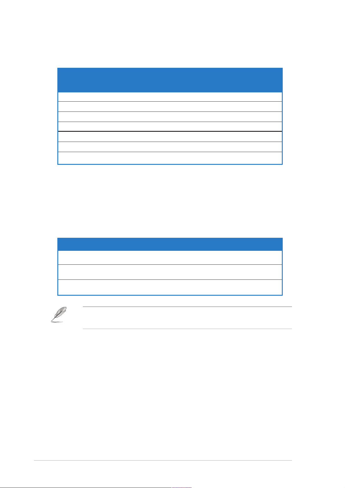
Table 1: Recommended memory configurations
Sockets
Mode/DIMM Type DIMM_A1 DIMM_A2 DIMM_B1 DIMM_B2
(blue) (black) (blue) (black)
Single-channel (1) Populated — — —
(DDR400/DDR333/
DDR266)
Dual-channel (1) Populated — Populated —
(DDR400/DDR333/
DDR266)
* For dual-channel configuration (3), you may:
• install identical DIMMs in all four sockets or
• install identical DIMM pair in DIMM_A1 and DIMM_B1 (blue sockets)
and identical DIMM pair in DIMM_A2 and DIMM_B2 (black sockets)
(2) — Populated — —
(3) — — Populated —
(4) — — — Populated
(2) — Populated — Populated
(3)* Populated Populated Populated Populated
Table 2: Memory frequency/CPU FSB synchronization
CPU FSB DDR DIMM Type Memory Frequency
800 MHz PC3200/PC2700*/PC2100 400/333*/266 MHz
533 MHz PC2700/PC2100 333/266 MHz
400 MHz PC2100 266 MHz
*When using 800MHz CPU FSB, PC2700 DDR DIMMs may run only at
320MHz (not 333MHz) due to the Southbridge resource allocation.
2-12
Chapter 2: Hardware information
 Loading...