


Q87T
Q87T/CSM
Motherboard

E8629
First Edition
September 2013
Copyright © 2013 ASUSTeK COMPUTER INC. All Rights Reserved.
No part of this manual, including the products and software described in it, may be reproduced, transmitted, transcribed, stored in a retrieval system, or translated into any language in any form or by any means, except documentation kept by the purchaser for backup purposes, without the express written permission of ASUSTeK COMPUTER INC. (“ASUS”).
Product warranty or service will not be extended if: (1) the product is repaired, modified or altered, unless such repair, modification of alteration is authorized in writing byASUS; or (2) the serial number of the product is defaced or missing.
ASUS PROVIDES THIS MANUAL “AS IS” WITHOUT WARRANTY OF ANY KIND, EITHER EXPRESS OR IMPLIED, INCLUDING BUT NOT LIMITED TO THE IMPLIED WARRANTIES OR CONDITIONS OF MERCHANTABILITY OR FITNESS FOR A PARTICULAR PURPOSE. IN NO EVENT SHALL ASUS, ITS DIRECTORS, OFFICERS, EMPLOYEES OR AGENTS BE LIABLE FOR ANY INDIRECT, SPECIAL, INCIDENTAL, OR CONSEQUENTIAL DAMAGES (INCLUDING DAMAGES FOR LOSS OF PROFITS, LOSS OF BUSINESS, LOSS OF USE OR DATA, INTERRUPTION OF BUSINESS AND THE LIKE), EVEN IF ASUS HAS BEEN ADVISED OF THE POSSIBILITY OF SUCH DAMAGES ARISING FROM ANY DEFECT OR ERROR IN THIS MANUAL OR PRODUCT.
SPECIFICATIONS AND INFORMATION CONTAINED IN THIS MANUAL ARE FURNISHED FOR INFORMATIONAL USE ONLY, AND ARE SUBJECT TO CHANGE AT ANY TIME WITHOUT NOTICE, AND SHOULD NOT BE CONSTRUED AS A COMMITMENT BY ASUS. ASUS ASSUMES NO RESPONSIBILITY OR LIABILITY FOR ANY ERRORS OR INACCURACIES THAT MAY APPEAR IN THIS MANUAL, INCLUDING THE PRODUCTS AND SOFTWARE DESCRIBED IN IT.
Products and corporate names appearing in this manual may or may not be registered trademarks or copyrights of their respective companies, and are used only for identification or explanation and to the owners’ benefit, without intent to infringe.
Offer to Provide Source Code of Certain Software
This product contains copyrighted software that is licensed under the General Public License (“GPL”), under the Lesser General Public License Version (“LGPL”) and/or other Free Open Source Software Licenses. Such software in this product is distributed without any warranty to the extent permitted by the applicable law. Copies of these licenses are included in this product.
Where the applicable license entitles you to the source code of such software and/or other additional data, you may obtain it for a period of three years after our last shipment of the product, either
(1)for free by downloading it from http://support.asus.com/download
or
(2)for the cost of reproduction and shipment, which is dependent on the preferred carrier and the location where you want to have it shipped to, by sending a request to:
ASUSTeK Computer Inc.
Legal Compliance Dept.
15 Li Te Rd.,
Beitou, Taipei 112
Taiwan
In your request please provide the name, model number and version, as stated in the About Box of the product for which you wish to obtain the corresponding source code and your contact details so that we can coordinate the terms and cost of shipment with you.
The source code will be distributed WITHOUT ANY WARRANTY and licensed under the same license as the corresponding binary/object code.
This offer is valid to anyone in receipt of this information.
ASUSTeK is eager to duly provide complete source code as required under various Free Open Source Software licenses. If however you encounter any problems in obtaining the full corresponding source code we would be much obliged if you give us a notification to the email address gpl@asus.com, stating the product and describing the problem (please DO NOT send large attachments such as source code archives, etc. to this email address).
ii

Contents
Safety information....................................................................................... |
iv |
About this guide.......................................................................................... |
iv |
Package contents........................................................................................ |
vi |
Q87T specifications summary................................................................... |
vi |
Product introduction
1.1 |
Before you proceed...................................................................... |
1-1 |
1.2 |
Motherboard overview................................................................. |
1-1 |
1.3 |
Central Processing Unit (CPU).................................................... |
1-3 |
1.4 |
System memory............................................................................ |
1-7 |
1.5 |
Expansion slots............................................................................ |
1-9 |
1.6 |
Jumpers....................................................................................... |
1-10 |
1.7 |
Connectors.................................................................................. |
1-13 |
1.8 |
Onboard LEDs............................................................................. |
1-21 |
1.9 |
Software support........................................................................ |
1-22 |
BIOS information
2.1 |
Managing and updating your BIOS............................................. |
2-1 |
2.2 |
BIOS setup program..................................................................... |
2-5 |
2.3 |
My Favorites.................................................................................. |
2-9 |
2.4 |
Main menu................................................................................... |
2-10 |
2.5 |
Ai Tweaker menu........................................................................ |
2-12 |
2.6 |
Advanced menu.......................................................................... |
2-23 |
2.7 |
Monitor menu.............................................................................. |
2-37 |
2.8 |
Boot menu................................................................................... |
2-40 |
2.9 |
Tools menu.................................................................................. |
2-47 |
2.10 |
Exit menu..................................................................................... |
2-48 |
Appendices
Notices....................................................................................................... |
A-1 |
ASUS contact information........................................................................ |
A-3 |
iii

Safety information
Electrical safety
•To prevent electrical shock hazard, disconnect the power cable from the electrical outlet before relocating the system.
•When adding or removing devices to or from the system, ensure that the power cables for the devices are unplugged before the signal cables are connected. If possible, disconnect all power cables from the existing system before you add a device.
•Before connecting or removing signal cables from the motherboard, ensure that all power cables are unplugged.
•Seek professional assistance before using an adapter or extension cord. These devices could interrupt the grounding circuit.
•Ensure that your power supply is set to the correct voltage in your area. If you are not sure about the voltage of the electrical outlet you are using, contact your local power company.
•If the power supply is broken, do not try to fix it by yourself. Contact a qualified service technician or your retailer.
Operation safety
•Before installing the motherboard and adding components, carefully read all the manuals that came with the package.
•Before using the product, ensure all cables are correctly connected and the power cables are not damaged. If you detect any damage, contact your dealer immediately.
•To avoid short circuits, keep paper clips, screws, and staples away from connectors, slots, sockets and circuitry.
•Avoid dust, humidity, and temperature extremes. Do not place the product in any area where it may be exposed to moisture.
•Place the product on a stable surface.
•If you encounter technical problems with the product, contact a qualified service technician or your retailer.
About this guide
This user guide contains the information you need when installing and configuring the motherboard.
How this guide is organized
This guide contains the following parts:
•Chapter 1: Product introduction
This chapter describes the features of the motherboard and the new technology it supports. It includes descriptions of the switches, jumpers, and connectors on the motherboard.
•Chapter 2: BIOS information
This chapter discusses changing system settings through the BIOS Setup menus. Detailed descriptions fo the BIOS parameters are also provided.
iv
Where to find more information
Refer to the following sources for additional information and for product and software updates.
1.ASUS websites
The ASUS website provides updated information on ASUS hardware and software products. Refer to the ASUS contact information.
2.Optional documentation
Your product package may include optional documentation, such as warranty flyers, that may have been added by your dealer. These documents are not part of the standard package.
Conventions used in this guide
To ensure that you perform certain tasks properly, take note of the following symbols used throughout this manual.
DANGER/WARNING: Information to prevent injury to yourself when completing a task.
CAUTION: Information to prevent damage to the components when completing a task
IMPORTANT: Instructions that you MUST follow to complete a task.
NOTE: Tips and additional information to help you complete a task.
Typography
Bold text |
Indicates a menu or an item to select. |
Italics |
Used to emphasize a word or a phrase. |
<Key> |
Keys enclosed in the less-than and greater-than sign |
|
means that you must press the enclosed key. |
|
Example: <Enter> means that you must press the Enter or |
|
Return key. |
<Key1> + <Key2> + <Key3> |
If you must press two or more keys simultaneously, the key |
|
names are linked with a plus sign (+). |
Package contents
Check your motherboard package for the following items.
Motherboard |
ASUS Q87T motherboard |
|
|
Cables |
2 x Serial ATA 6.0 Gb/s cables, 1 x SATA power cable |
|
|
Accessories |
2 x I/O Shield (1 x mini-ITX, 1 x thin mini-ITX) |
|
|
Application DVD |
Support DVD |
|
|
Documentation |
User Guide |
|
|
If any of the above items is damaged or missing, contact your retailer.
Q87T specifications summary
CPU
Chipset
Memory
Graphics
Expansion slots
LGA1150 socket for Intel® 4th Generation Core™ i7 / i5 / i3, Pentium®, and Celeron® processors
Supports 22nm CPU*
Supports Intel® Turbo Boost Technology 2.0**
*Up to 65W Thermal Design Power support for Intel® standard thin mini-ITX heatsink. Up to 84W Thermal Design Power support for standard 1150/1155 heatsink.
**Intel® Turbo Boost Technology 2.0 support depends on the CPU type.
***Refer to www.asus.com for Intel® CPU support list.
Intel® Q87 Express Chipset
2 x SO-DIMMs, max. 16GB, DDR3 1600 / 1333 / 1066 MHz, non-ECC, un-buffered memory
Dual-channel memory architecture
*Refer to www.asus.com for the latest Memory QVL (Qualified Vendors List).
**When you install a total memory of 4GB capacity or more, Windows® 32-bit operating system may only recognize less than 3GB. We recommend a maximum of 3GB system memory if you are using a Windows® 32-bit operating system.
Integrated graphics processor
Multi-VGA output support: DisplayPort / eDP / HDMI / LVDS*
-Supports DisplayPort 1.2 / eDP with max. resolution of 4096 x
2160@24Hz / 3840 x 2160 @60Hz
-Supports HDMI with max. resolution of 4096 x 2160 @24Hz / 2560 x 1600 @60Hz
-Supports LVDS with max.resolution of 1920 x 1200 @60Hz
Maximum shared memory of 1024 MB
*LVDS and eDP share the same video output. An onboard header is available to switch output.
1 x PCI Express 3.0/2.0 x4 slot
1 x mini PCIe (full length, with mSATA support)
1 x mini PCIe (half length)
*mSATA shares the same slot with the full-length mini PCIe. When an mSATA card is inserted, the mini PCIe slot is not available.
(continued on the next page)
vi

Q87T specifications summary
Storage |
Intel® Q87 Express Chipset: |
|
|
- 4 x Serial ATA 6.0 Gb/s connector |
|
|
- 1 x mSATA connector* |
|
|
*mSATA shares the same slot with the full-length mini-PCIe card. A mini-PCIe |
|
LAN |
card cannot be used if an mSATA card is inserted into the slot. |
|
Dual LAN support |
|
|
|
- Intel® I217LM Gigabit LAN controller |
|
Audio |
- Realtek® 8111G Gigabit LAN controller |
|
8-channel Realtek® ALC887-VD High DefinitionAudio CODEC |
|
|
|
- Supports Jack-Detection, Multi-streaming, Anti-pop Function, Front |
|
|
Panel Retasking |
|
USB
ASUS unique features
Rear panel I/O ports
*Use a chassis with HD audio module in the front panel to support an 8- channel audio output.
5 x USB 2.0 ports (5 ports at mid-board, 2 x 2-port header and 1 x 1-port header)
6 x USB 3.0 ports (2 ports at mid-board, 4 ports at back panel)
ASUS EZ DIY:
-ASUS CrashFree BIOS 3
-ASUS EZ Flash 2
-ASUS MyLogo 2™
ASUS Exclusive Features
-ASUS USB 3.0 Boost
-ASUS Network iControl
-ASUS AI Suite III
-ASUS Ai Charger
-ASUS UEFI BIOS EZ Mode
-ASUS Enhanced DRAM Overcurrent Protection - Short circuit damage prevention
-ASUS ESD Guards - Enhanced ESD protection
ASUS Quiet Thermal Solution:
- ASUS Fan Xpert
100% Solid Capacitors
1 x DC Power connector
1 x DisplayPort port
1 x HDMI port
2 x LAN (RJ-45) port
4 x USB 3.0 ports
2 x Audio jacks
(continued on the next page)
vii

Q87T specifications summary
Internal connectors/ switches/ buttons
BIOS features
Manageability
Support DVD
Form factor
1 x USB 3.0 connector supports additional 2 USB 3.0 ports
2 x USB 2.0 2-port connectors support additional 4 USB 2.0 ports 1 x USB 2.0 1-port connectors support additional 1 USB 2.0 ports 1 x eDP connector
1 x LVDS connector
1 x eDP/LVDS switch jumper
4 x SATA 6.0Gb/s connector
1 x mSATA connector
1 x CPU fan connector
1 x Chassis fan connector
1 x Front panel audio connector (AAFP)
1 x System panel connector
1 x Clear CMOS jumper
1 x DIS ME jumper
1 x COM port header
1 x Chassis intrusion header
1 x SATA power connector
Connectors for AIO System
1 x 2-pin internal DC power connector
1 x Stereo speaker connector
1 x DMIC header
1 x Custom solutions header
Connectors for Flat Panel Display
1 x Backlight inverter voltage selection header
1 x FPD brightness header
1 x Panel voltage selection header
1 x Panel off header
TPM IC Onboard
128 Mb Flash ROM, AMI BIOS, PnP, DMI v2.0, WfM2.0, SM BIOS v2.5, ACPI v2.0a, Multi-language BIOS, ASUS EZ Flash 2, ASUS CrashFree BIOS 3
WfM 2.0, DMI 2.0, WOL by PME, WOR by PME, PXE
Drivers
ASUS utilities
ASUS Update
Anti-virus software (OEM version)
Thin mini-ITX form factor: 6.7”x 6.7” (17.0cm x 17.0cm)
Specifications are subject to change without notice.
viii
Product introduction |
1 |
1.1Before you proceed
Take note of the following precautions before you install motherboard components or change any motherboard settings.
• Unplug the power cord from the wall socket before touching any component.
• Before handling components, use a grounded wrist strap or touch a safely grounded object or a metal object, such as the power supply case, to avoid damaging them due to static electricity.
•Hold components by the edges to avoid touching the ICs on them.
•Whenever you uninstall any component, place it on a grounded antistatic pad or in the bag that came with the component.
•Before you install or remove any component, ensure that the ATX power supply is switched off or the power cord is detached from the power supply. Failure to do so may cause severe damage to the motherboard, peripherals, or components.
1.2Motherboard overview
Before you install the motherboard, study the configuration of your chassis to ensure that the motherboard fits.
Unplug the power cord before installing or removing the motherboard. Failure to do so can cause you physical injury and damage to motherboard components.
1.2.1Placement direction
When installing the motherboard, place it into the chassis in the correct orientation. The edge with external ports goes to the rear part of the chassis as indicated in the image.
ASUS Q87T |
1-1 |
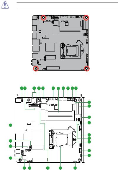
1.2.2Screw holes
Place six screws into the holes indicated by circles to secure the motherboard to the chassis.
Do not overtighten the screws! Doing so can damage the motherboard.
Q87T
Place this side 
 towards the rear
of the chassis
1.2.3Motherboard layout
1 |
2 |
3 |
4 |
3 |
5 |
6 |
7 |
8 |
9 |
4 |
17cm(6.7in)
DC_PWR
ATX19V1
|
|
|
|
4 2 |
CHA_FAN |
||||
|
|
USB3_56 |
|
|
|
SATA6G |
SATA_PWRCON |
||
|
|
|
|
|
|
|
|
SATA6G |
USB14 |
|
|
|
|
|
|
|
|
|
|
|
|
HDMI |
|
|
|
|
|
|
|
|
|
|
|
|
|
|
|
|
|
|
|
|
|
|
|
|
|
|
|
|
|
|
|
ASM |
|
|
|||
|
|
|
|
1442K |
|
|
|||
|
|
DP |
|
|
|
|
|
|
128Mb |
25 |
|
|
|
|
|
|
|
|
BIOS |
|
|
|
|
|
|
|
BATT_CON |
||
|
|
|
|
|
|
|
|
||
|
|
|
|
|
|
|
|
||
|
|
LAN2 |
|
|
|
|
RTL |
|
|
|
|
|
|
|
|
|
|
8111G |
Intel® |
|
|
|
|
|
|
|
|
|
|
|
|
|
|
|
|
|
|
|
|
|
|
LAN1 |
|
|
|
|
|
Q87 |
|
USB3_12 |
COM1 |
F_PANEL |
SATA6G_3 |
MON_SW_PANEL CPU_FAN |
|
SATA6G_1 |
|
|
MSATA_MPCIE
Super
I/O
DDR3 DIMM_A1 (64bit, 204-pin module)
DDR3 DIMM_B1 (64bit, 204-pin module)
EDP |
LVDS |
PANEL |
|
|
LCD BLKT_ |
PWR SEL |
FPD SEL |
|
VCC_ |
BLKT PWR SEL |
|
|
17cm(6.7in) |
|
|
USB910 |
24 |
|
LGA1150 |
DEBUG |
23 |
USB3_34 |
||
|
WLAN |
LPC |
HP-OUT
MIC
22
INT_SPK |
|
USB78 |
|
CUSTOM |
AAFP |
|
|
ALC887 |
|
CLRTC |
-VD2 |
PCIEX4 |
|
DIS_ME |
CHASSIS |
|
|
DMIC |
|
|
|
21 |
20 |
14 |
19 |
18 |
10
11
12
13
14
15
16
14
17
1-2 |
Chapter 1: Product introduction |
1.2.4Layout contents
Connectors/Jumpers/Slots/LED |
Page |
|
1. |
ATX power connector (2-pin ATX19V) |
1-15 |
2. |
SATA power connector (15-pin SATA_PWRCON) |
1-16 |
3. |
Intel® Q87 Serial ATA 6.0Gb/s connector (7-pin SATA6G_1~4 [yellow]) |
1-15 |
4. |
CPU and chassis fan connectors (4-pin CPU_FAN, 4-pin CHA_FAN) |
1-14 |
5. |
USB 3.0 connector (20-1 pin USB3_12) |
1-17 |
6. |
DDR3 SO-DIMM slots |
1-7 |
7. |
Serial port connector (10-1 pin COM) |
1-14 |
8. |
System panel connector (10-1 pin F_PANEL) |
1-18 |
9. |
Display panel power button (2-1 pin MON_SW_PANEL) |
1-18 |
10. |
Embedded DisplayPort (30-pin eDP) |
1-19 |
11. |
LVDS connector (30-pin LVDS) |
1-19 |
12. |
Flat panel display brightness (8-pin LCD_BLKT_PANEL) |
1-20 |
13. |
Display panel backlight power selector (BLKT_PWR-SEL) |
1-12 |
14. |
USB 2.0 connectors (5-1 pin USB14, 10-1 pin USB78, 10-2 pin USB910) |
1-17 |
15. |
LVDS panel or eDP selector (3-pin FPD_SEL) |
1-12 |
16. |
Display panel VCC power selector (6-pin VCC_PWR_SEL) |
1-12 |
17. |
Clear RTC RAM (3-pin CLRTC) |
1-10 |
18. |
Chassis intrusion connector (4-1 pin CHASSIS) |
1-11 |
19. |
Intel® LGA1150 CPU socket |
1-3 |
20. |
DMIC connectors (5-1 pin DMIC) |
1-20 |
21. |
Intel® ME jumper (3-pin DIS_ME) |
1-11 |
22. |
Front panel audio connector (10-1 pin AAFP) |
1-16 |
23. |
Internal stereo speaker header (4-pin INT_SPK) |
1-20 |
24. |
Custom header (14-1 pin CUSTOM) |
1-20 |
25. |
RTC battery header (2-pin BATT_CON) |
1-19 |
1.3Central Processing Unit (CPU)
This motherboard comes with a surface mount LGA1150 socket designed for the Intel 4th generation Core™ i7 / Core™ i5 / Core™ i3, Pentium® , Celeron® processors.
Q87T CPU socket LGA1150
ASUS Q87T |
1-3 |
Unplug all power cables before installing the CPU.
•Upon purchase of the motherboard, ensure that the PnP cap is on the socket and the socket contacts are not bent. Contact your retailer immediately if the PnP cap is missing, or if you see any damage to the PnP cap/socket contacts/motherboard components. ASUS will shoulder the cost of repair only if the damage is shipment/ transit-related.
•Keep the cap after installing the motherboard. ASUS will process Return Merchandise
Authorization (RMA) requests only if the motherboard comes with the cap on the
LGA1150 socket.
•The product warranty does not cover damage to the socket contacts resulting from incorrect CPU installation/removal, or misplacement/loss/incorrect removal of the PnP cap.
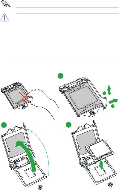
1.3.1Installing the CPU
1
A
B
2 |
3 |
1-4 |
Chapter 1: Product introduction |
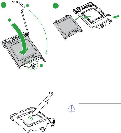
4 C 5
A
1.3.2CPU heatsink and fan assembly installation
Apply the Thermal Interface Material to the CPU heatsink and CPU before you install the heatsink and fan if necessary.
ASUS Q87T |
1-5 |

To install the CPU heatsink and fan assembly
1 A 2
B
B
A 
3 |
4 |
To uninstall the CPU heatsink and fan assembly
1 |
2 |
A |
B
B
A
1-6 |
Chapter 1: Product introduction |
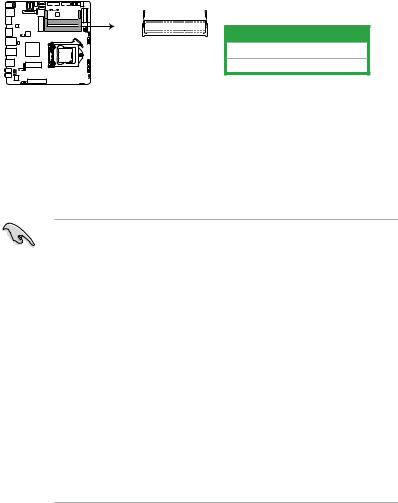
1.4System memory
1.4.1Overview
This motherboard comes with two Double Data Rate 3 (DDR3) Small Outline Dual Inline
Memory Module (SO-DIMM) sockets. The figure illustrates the location of the DDR3 SO-
DIMM sockets:
DIMM_A1  DIMM_B1


Channel |
Sockets |
Channel A |
DIMM_A1 |
Channel B |
DIMM_B1 |
Q87T 204-pin DDR3 DIMM sockets
1.4.2Memory configurations
You may install 1GB, 2GB, 4GB, and 8GB unbuffered non-ECC DDR3 DIMMs into the DIMM sockets.
•You may install varying memory sizes in ChannelAand Channel B. The system maps the total size of the lower-sized channel for the dual-channel configuration.Any excess memory from the higher-sized channel is then mapped for single-channel operation.
•Always install DIMMs with the same CAS latency. For optimal compatibility, we recommend that you install memory modules of the same version or date code (D/C) from the same vendor. Check with the retailer to get the correct memory modules.
•Due to the memory address limitation on 32-bit Windows® OS, when you install 4GB or more memory on the motherboard, the actual usable memory for the OS can be about 3GB or less. For effective use of memory, we recommend that you do any of the following:
-Use a maximum of 3GB system memory if you are using a 32-bit Windows® OS.
-Install a 64-bit Windows® OS if you want to install 4GB or more on the motherboard.
•This motherboard does not support DIMMs made up of 512 megabits (Mb) chips or less.
•Memory modules with memory frequency higher than 2133 MHz and its corresponding timing or the loaded X.M.P. Profile is not the JEDEC memory standard. The stability and compatibility of these memory modules depend on the CPU’s capabilities and other installed devices.
•The maximum 16GB memory capacity can be supported with 8GB or above DIMMs. ASUS will update the memory QVL once the DIMMs are available in the market.
ASUS Q87T |
1-7 |
• The default memory operation frequency is dependent on its Serial Presence Detect (SPD), which is the standard way of accessing information from a memory module. Under the default state, some memory modules for overclocking may operate at a lower frequency than the vendor-marked value. To operate at the vendor-marked
or at a higher frequency, refer to section 2.5 Ai Tweaker menu for manual memory frequency adjustment.
•For system stability, use a more efficient memory cooling system to support a full memory load (4 DIMMs) or overclocking condition.
•Visit the ASUS website at: www.asus.com for the latest QVL.
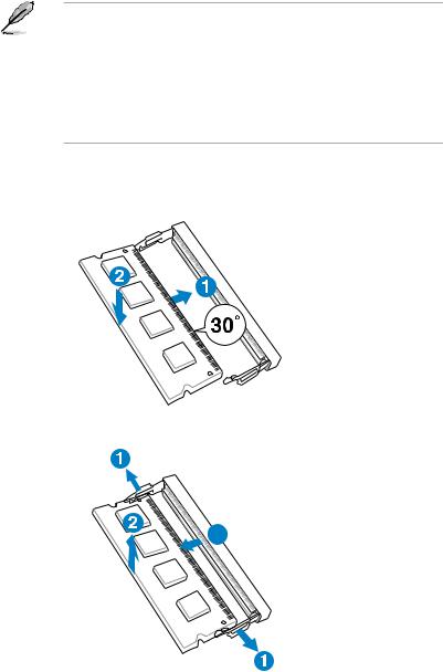
1.4.3Installing a DIMM
To install a DIMM
To remove a DIMM
3
1-8 |
Chapter 1: Product introduction |
1.5Expansion slots
In the future, you may need to install expansion cards. The following sub sections describe the slots and the expansion cards that they support.
Unplug the power cord before adding or removing expansion cards. Failure to do so may cause you physical injury and damage motherboard components.
1.5.1Installing an expansion card
To install an expansion card:
1.Before installing the expansion card, read the documentation that came with it and make the necessary hardware settings for the card.
2.Remove the system unit cover (if your motherboard is already installed in a chassis).
3.Remove the bracket opposite the slot that you intend to use. Keep the screw for later use.
4.Align the card connector with the slot and press firmly until the card is completely seated on the slot.
5.Secure the card to the chassis with the screw you removed earlier.
6.Replace the system cover.
1.5.2Configuring an expansion card
After installing the expansion card, configure it by adjusting the software settings.
1.Turn on the system and change the necessary BIOS settings, if any. See Chapter 2 for information on BIOS setup.
2.Assign an IRQ to the card.
3.Install the software drivers for the expansion card.
When using PCI cards on shared slots, ensure that the drivers support “Share IRQ” or that the cards do not need IRQ assignments. Otherwise, conflicts will arise between the two PCI groups, making the system unstable and the card inoperable.
1.5.3PCI Express 3.0/2.0 x4 slot
This motherboard supports PCI Express x4 network cards, SCSI cards, and other cards that comply with the PCI Express specifications.
IRQ assignments for this motherboard
|
A |
B |
C |
D |
E |
F |
G |
H |
Intel PCH SATA controller #0 |
– |
– |
– |
shared |
– |
– |
– |
– |
|
|
|
|
|
|
|
|
|
Intel PCH SATA controller #1 |
– |
– |
– |
shared |
– |
– |
– |
– |
Realtek 8111G controller |
– |
– |
shared |
– |
– |
– |
– |
– |
ASUS Q87T |
1-9 |
1.6Jumpers
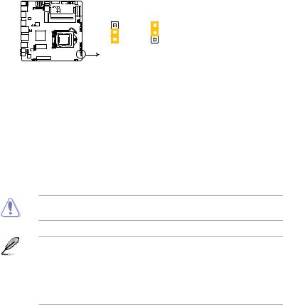
1.Clear RTC RAM (3-pin CLRTC)
This jumper allows you to clear the Real Time Clock (RTC) RAM in CMOS. You can clear the CMOS memory of date, time, and system setup parameters by erasing the CMOS RTC RAM data. The onboard button cell battery powers the RAM data in CMOS, which include system setup information such as system passwords.
CLRTC
|
3 |
2 |
2 |
1 |
|
Normal |
Clear RTC |
(Default) |
|
Q87T Clear RTC RAM
To erase the RTC RAM:
1.Turn OFF the computer and unplug the power cord.
2.Move the jumper cap from pins 1-2 (default) to pins 2-3. Keep the cap on pins 2-3 for about 5-10 seconds, then move the cap back to pins 1-2.
3.Plug the power cord and turn ON the computer.
4.Hold down the <Del> key during the boot process and enter BIOS setup to reenter data.
Except when clearing the RTC RAM, never remove the cap on CLRTC jumper default position. Removing the cap will cause system boot failure!
•If the steps above do not help, remove the onboard battery and move the jumper again to clear the CMOS RTC RAM data. After clearing the CMOS, reinstall the battery.
•You do not need to clear the RTC when the system hangs due to overclocking. For system failure due to overclocking, use the CPU Parameter Recall (C.P.R.) feature. Shut down and reboot the system, then the BIOS automatically resets parameter settings to default values.
1-10 |
Chapter 1: Product introduction |
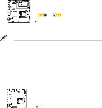
2.Intel® ME jumper (3-pin DIS_ME)
This jumper allows you to enable or disable the Intel® ME function. Set this jumper to pins 1-2 to enable (default) the Intel® ME function and to pins 2-3 to disable it.
DIS_ME
1 |
2 |
2 |
3 |
Normal |
Disable ME |
||
(Default) |
|
|
|
Q87T Intel® ME jumper
Disable the Intel® ME function before updating it.
3.Chassis intrusion connector (4-1 pin CHASSIS)
This connector is for a chassis-mounted intrusion detection sensor or switch. Connect one end of the chassis intrusion sensor or switch cable to this connector. The chassis intrusion sensor or switch sends a high-level signal to this connector when a chassis component is removed or replaced. The signal is then generated as a chassis intrusion event.
By default, the pins labeled “Intruder” are shorted with a jumper cap. Remove the jumper caps only when you intend to use the chassis intrusion detection feature.
CHASSIS
|
|
|
|
|
|
|
|
|
|
|
|
|
|
|
|
|
|
|
|
+5VSB MB |
Chassis Signal GND |
|
|
|
|
|
|
|
|
|
|
|
|
|
|
|
|
|
|
|
|
||
|
|
|
|
|
|
|
|
|
|
|
|
|
|
|
|
|
|
|
|
|
|

 PIN 1
PIN 1


Q87T Chassis intrusion connector
ASUS Q87T |
1-11 |
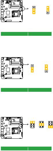
4.Display panel backlight power selector (BLKT_PWR_SEL)
BLKT_PWR_SEL
|
3 |
2 |
2 |
1 |
|
12V |
19V |
(Default) |
|
Q87T Display panel backlight power selection
|
|
Pins |
Setting |
1-2 |
12V |
2-3 |
19V |
5.LVDS panel or eDP selector (3-pin FPD_SEL)
FPD_SEL
|
3 |
2 |
2 |
1 |
|
for LVDS |
for eDP |
(Default) |
|
Q87T LVDS or eDP selection
|
|
Pins |
Setting |
1-2 |
LVDS (Default) |
2-3 |
eDP |
6.Display panel VCC power selector (VCC_PWR_SEL)
VCC_PWR_SEL
1 |
|
2 |
|
|
|
|
|
3 |
3V |
5V |
12V |
(Default) |
|
|
Q87T Display panel VCC power
|
|
Pins |
Setting |
1 |
3V |
2 |
5V |
3 |
12V |
1-12 |
Chapter 1: Product introduction |
1.7Connectors
1.7.1Rear panel connectors
|
1 |
|
2 |
|
|
3 |
|
4 |
|
|
|
|
|
5 |
|
|
|
|
|
|
6 |
|
7 |
8 |
|||||||||||||||
|
|
|
|
|
|
|
|
|
|
|
|
|
|
|
|
|
|
|
|
|
|
|
|
|
|
|
|
|
|
|
|
|
|
|
|
|
|
|
|
|
|
|
|
|
|
|
|
|
|
|
|
|
|
|
|
|
|
|
|
|
|
|
|
|
|
|
|
|
|
|
|
|
|
|
|
|
|
|
|
|
|
|
|
|
|
|
|
|
|
|
|
|
|
|
|
|
|
|
|
|
|
|
|
|
|
|
|
|
|
|
|
|
|
|
|
|
|
|
|
|
|
|
|
|
|
|
|
|
|
|
|
|
|
|
|
|
|
|
|
|
|
|
|
|
|
|
|
|
|
|
|
|
|
|
|
|
|
|
|
|
|
|
|
|
|
|
|
|
|
|
|
|
|
|
|
|
|
|
|
|
|
|
|
|
|
|
|
|
|
|
|
|
|
|
|
|
|
|
|
|
|
|
|
|
|
|
|
|
|
|
|
|
|
|
|
|
|
|
|
|
|
|
|
|
|
|
|
|
|
|
|
|
|
|
|
|
|
|
|
|
|
|
|
|
|
|
|
|
|
|
|
|
|
|
|
|
|
|
|
|
|
|
|
|
|
|
|
|
|
|
|
|
|
|
|
|
|
|
|
1.DC power connector. Insert the power adapter into this port.
2.USB 3.0 ports 5 and 6. These two 9-pin Universal Serial Bus (USB) ports are for connecting USB 3.0 devices.
3.HDMI port. This port is for a High-Definition Multimedia Interface (HDMI) connector, and is HDCP compliant allowing playback of HD DVD, Blu-ray, and other protected content.
4.DisplayPort. Connect a DisplayPort cable into this port for high-definition video and audio.
5.LAN (RJ-45) port. These ports allow Gigabit connection to a Local Area Network (LAN) through a network hub.
LAN port LED indications
Activity/Link LED |
Speed LED |
||
Status |
Description |
Status |
Description |
OFF |
No link |
OFF |
10Mbps connection |
GREEN |
Linked |
ORANGE |
100Mbps connection |
GREEN |
Data activity |
GREEN |
1Gbps connection |
ACT/LINK SPEED LED LED
LAN port
6.USB 3.0 ports 3 and 4. These two 9-pin Universal Serial Bus (USB) ports are for connecting USB 3.0 devices.
7.Line Out port (lime). This port connects to a headphone or a speaker.
8.Microphone port (pink). This port connects to a microphone.
ASUS Q87T |
1-13 |
1.7.2Internal connectors
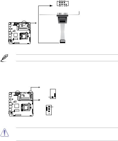
1.Serial port connector (10-1 pin COM)
This connector is for a serial (COM) port. Connect the serial port module cable to this connector, then install the module to a slot opening at the back of the system chassis.
PIN 1
COM RXD DTR DSR CTS
DCDTXDGNDRTSRI
Q87T Serial port connector
The COM module is purchased separately.
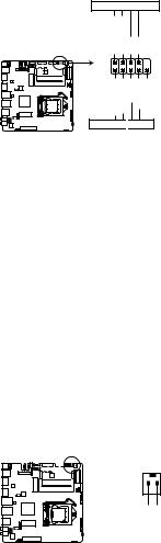
2.CPU and chassis fan connectors (4-pin CPU_FAN, and 4-pin CHA_FAN)
Connect the fan cables to the fan connectors on the motherboard, ensuring that the black wire of each cable matches the ground pin of the connector.
CPU_FAN
CPU FAN PWM 
CPU FAN IN 


CPU FAN PWR 

GND
CHA_FAN
GND
 CHA FAN PWR

 CHA FAN IN
 CHA FAN PWM
Q87T Fan connectors
DO NOT forget to connect the fan cables to the fan connectors. Insufficient air flow inside the system may damage the motherboard components. These are not jumpers! DO NOT place jumper caps on the fan connectors.
1-14 |
Chapter 1: Product introduction |
3.ATX power connector (2-pin ATX19V)
This connector is for an ATX power supply. The plug from the power supply is designed to fit this connector in only one orientation. Find the proper orientation and push down firmly until the connector completely fits.
ATX19V
_DC IN_JACK
 PIN 1
PIN 1
GND
Q87T DC power source
4.Serial ATA 6.0 Gb/s connectors (7-pin SATA6G 1~4)
These connectors connect to Serial ATA 6.0 Gb/s hard disk drives via Serial ATA 6.0 Gb/s signal cables.
SATA6G_2 SATA6G_4
|
|
|
|
|
|
|
|
|
|
|
|
|
|
|
|
|
|
|
|
|
GND |
|
|
GND |
|
|
|
|
|
|
|
|
|
|
|
|
|
|
|
|
|
|
|
|
|
RSATA_RXP4 |
|
|
RSATA_RXP2 |
|
|
|
|
|
|
|
|
|
|
|
|
|
|
|
|
|
|
|
|
|
RSATA_RXN4 |
|
|
RSATA_RXN2 |
|
|
|
|
|
|
|
|
|
|
|
|
|
|
|
|
|
|
|
|
|
GND |
|
|
GND |
|
|
|
|
|
|
|
|
|
|
|
|
|
|
|
|
|
|
|
|
|
RSATA_TXN4 |
|
|
RSATA_TXN2 |
|
|
|
|
|
|
|
|
|
|
|
|
|
|
|
|
|
|
|
|
|
RSATA_TXP4 |
|
|
RSATA_TXP2 |
|
|
|
|
|
|
|
|
|
|
|
|
|
|
|
|
|
|
|
|
|
GND |
|
|
GND |
|
|
|
|
|
|
|
|
|
|
|
|
|
|
|
|
|
|
|
|
|
|
|
|
|
|
|
|
|
|
|
|
|
|
|
|
|
|
|
|
|
|
|
|
|
|
|
|
|
|
|
|
|
|
|
|
|
|
|
|
|
|
|
|
|
|
|
|
|
|
|
|
|
|
|
|
|
|
|
|
|
|
|
|
|
|
|
|
|
|
|
|
|
|
|
|
|
|
|
|
|
|
|
|
|
|
|
|
|
|
|
|
|
|
|
|
|
|
|
|
|
|
|
|
|
|
|
|
|
|
|
|
|
|
|
|
|
|
|
|
|
|
|
|
|
|
|
|
|
|
SATA6G_3
GND RSATA_RXP1 RSATA_RXN1 GND RSATA_TXN1 RSATA_TXP1 GND
SATA6G_1
GND RSATA_RXP3 RSATA_RXN3 GND RSATA_TXN3 RSATA_TXP3 GND
Q87T SATA 6.0Gb/s connectors
When using hot-plug and NCQ, set the type of the SATA connectors in the BIOS to [AHCI]. See section 2.6.4 SATA Configuration for details.
ASUS Q87T |
1-15 |
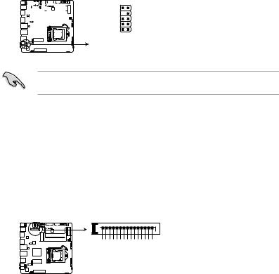
5.Front panel audio connector (10-1 pin AAFP)
This connector is for a chassis-mounted front panel HD audio I/O module. Connect one end of the front panel audio I/O module cable to this connector.
|
|
|
|
|
|
|
|
|
|
|
|
|
|
AAFP |
||||
|
|
|
|
|
|
|
|
|
|
|
|
|
SENSE2_RETUR |
|
|
|
|
PORT2 L |
|
|
|
|
|
|
|
|
|
|
|
|
|
|
|
|
|
|
SENSE_SEND |
|
|
|
|
|
|
|
|
|
|
|
|
|
SENSE1_RETUR |
|
|
|
|
PORT2 R |
|
|
|
|
|
|
|
|
|
|
|
|
|
||||||
|
|
|
|
|
|
|
|
|
|
|
|
|
||||||
|
|
|
|
|
|
|
|
|
|
|
|
|
NC |
|
|
|
|
PORT1 R |
|
|
|
|
|
|
|
|
|
|
|
|
|
AGND |
|
|
|
|
PORT1 L |
|
|
|
|
|
|
|
|
|
|
|
|
|
|
|
|
|
PIN 1 |
|
|
|
|
|
|
|
|
|
|
|
|
|
|
|
|
|
|
||
HD-audio-compliant
pin definition
Q87T Front panel audio connector
We recommend that you connect a high-definition front panel audio module to this connector to avail of the motherboard’s high-definition audio capability.
6.SATA power connector (15-pin SATA_PWRCON)
This connector is for the SATA power cable. The power cable plug is designed to fit this connector in only one orientation. Find the proper orientation and push down firmly until the connector completely fit. To provide power to your SATA device, connect the SATA power cable to this connector.
SATA_PWRCON
PIN 1
+12V +12V +12V GND GND GND +5V +5V +5V GND GND GND +3V +3V +3V
Q87T SATA HDD power source
1-16 |
Chapter 1: Product introduction |
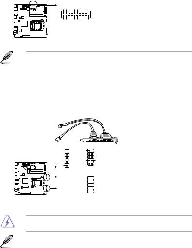
7.USB 3.0 connector (20-1 pin USB3_12)
This connector allows you to connect a USB 3.0 module for additional USB 3.0 front or rear panel ports. With an installed USB 3.0 module, you can enjoy all the benefits of
USB 3.0 including faster data transfer speeds of up to 4.8Gbps, faster charging time for
USB-chargeable devices, optimized power efficiency, and backward compatibility with
USB 2.0.
USB3_12
P2_IntA P2_IntAGNDP2_IntA P2_IntAGNDP2_IntA P2_IntA _D_____USB3+5V D+-SSTXSSRX SSTX+-SSRX+-
PIN 1
USB3+5V
IntA_P1_SSRX-
IntA_P1_SSRX+
IntA_P1_SSTX-
GND
IntA_P1_SSTX+
GND
IntA_P1_D-
IntA_P1_D+
GND
Q87T USB3.0 Front panel connector
The USB 3.0 module is purchased separately.
8.USB 2.0 connectors (10-1 pin USB14, USB78, USB910)
These connectors are for USB 2.0 ports. Connect the USB module cable to any of these connectors, then install the module to a slot opening at the back of the system chassis. These USB connectors comply with USB 2.0 specifications and supports up to
480Mbps connection speed.
USB14 |
USB78 |
||
|
|
NC |
|
GND |
|
GND |
GND |
GND |
|
USB_P7+ |
USB_P8+ |
USBD+ |
|
USB_P7- |
USB_P8- |
USBD- |
|
USB+5V |
USB+5V |
+5V |
PIN 1 |
PIN 1 |
|
|
|||
USB910
GND 
 GND
GND
USB_P9+ 
 USB_P10+
USB_P9- 


 USB_P10-
USB+5V 
 USB+5V
PIN 1
Q87T USB2.0 connectors
Never connect a 1394 cable to the USB connectors. Doing so will damage the motherboard!
The USB 2.0 module is purchased separately.
ASUS Q87T |
1-17 |
9.System panel connector (10-1 pin PANEL)
This connector supports several chassis-mounted functions.
F_PANEL
+PWR LED 
 PWR BTN
_PWR LED_PWRPWRGND LED+-
PIN 1
LED+-LEDGroundHWRST#(NC)
_HDD _HDD
+HDD_LED 
 RESET
RESET
Q87T System panel connector
•System power LED (2-pin PWR_LED)
This 2-pin connector is for the system power LED. Connect the chassis power LED cable to this connector. The system power LED lights up when you turn on the system power, and blinks when the system is in sleep mode.
•Hard disk drive activity LED (2-pin HDD_LED)
This 2-pin connector is for the HDD Activity LED. Connect the HDD Activity LED cable to this connector. The HDD LED lights up or flashes when data is read from or written to the HDD.
•ATX power button/soft-off button (2-pin PWR_BTN)
This connector is for the system power button.
•Reset button (2-pin RESET)
This 2-pin connector is for the chassis-mounted reset button for system reboot without turning off the system power.
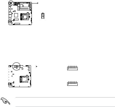
10.Display panel power button (2-1 pin MON_SW_PANEL)
This connector is used for the display panel power switch.


 MON_SW_PANEL
PIN 1
GND
MON_SW#
Q87T Display panel power button
1-18 |
Chapter 1: Product introduction |
 Loading...