


English
Pundit P3-PH4/P3-PH5
ASUS PC (Desktop Barebone)
Installation Manual
Download the latest manual from the ASUS website: www.asus.com
English
Front panel features
Close |
|
|
|
Open |
||||||||
|
|
Optical drive |
|
|
|
|
|
|
|
|
|
Front panel cover |
|
|
eject button |
|
|
|
|
|
|
|
|
|
|
|
|
|
|
|
|
|
|
|
|
|||
|
|
Memory Stick®/ |
|
|
|
|
|
|
|
|
|
SmartMedia® card slot |
|
|
Pro™card slot |
|
|
|
|
|
|
|
|
|
|
|
|
|
|
|
|
|
|
|
|
|||
|
Optical drive bay cover |
|
|
|
|
|
|
|
|
|
Card reader LED |
|
|
|
|
|
|
|
|
|
|
|
|||
|
|
|
|
|
|
|
|
|
|
Secure Digital™/ |
||
|
|
CompactFlash® |
|
|
|
|
|
|
|
|
|
|
|
|
|
|
|
|
|
|
|
|
|
||
|
|
card slot |
|
|
|
|
|
|
|
|
|
MultimediaCard slot |
|
|
HDD LED |
|
|
|
|
|
|
|
|
|
|
|
|
Power LED |
|
|
|
|
|
|
|
|
|
|
|
|
|
|
|
|
|
|
|
|
|
||
|
|
Power button |
|
|
|
|
|
|
|
|
|
Headphone port |
|
|
|
|
|
||||||||
|
|
|
|
|
|
|
|
|
|
|
|
Microphone port |
|
|
|
|
|
|
|
|
|
|
|
|
|
|
|
Press to open the |
|
|
|
|
|
|
|
|
|
IEEE 1394a port |
|
|
|
|
|
|
|
|
|
|
|
||
|
|
|
|
|
|
|
|
|
|
|
USB 2.0 ports |
|
|
|
front panel cover |
|
|
|
|
|
|
|
|
|
|
|
|
|
|
|
|
|
|
|
|
|||
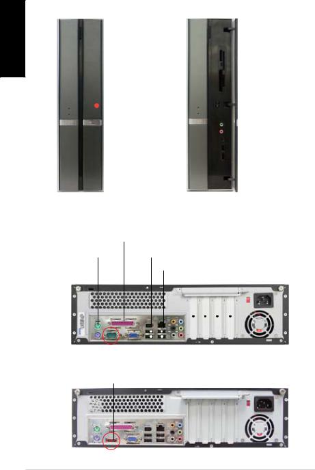
Rear panel features
|
|
|
|
|
|
|
|
Parallel port |
|
|
|
|
|
|
|
|
|
|
|
|
|
|
|||
|
|
|
|
|
|
|
|
Air vents |
Voltage selector |
|||
PS/2 mouse port |
|
|
|
|
IEEE 1394a port |
|
Power connector |
|||||
|
|
|
|
|
|
|
|
|
||||
Cover screw |
|
|
|
|
LAN (RJ-45) port |
|
||||||
|
|
|
|
|
|
Cover |
screw |
|||||
|
|
|
|
Metal bracket lock |
|
|||||||
|
|
|
|
|
|
|
|
|
||||
|
|
|
|
|
|
|
|
|
|
|
|
|
|
|
|
|
|
|
|
|
|
|
|
|
|
|
|
|
|
|
|
|
|
|
|
|
|
|
|
|
|
|
|
|
|
|
|
|
|
|
|
|
|
|
|
|
|
|
|
|
|
|
|
|
|
|
|
|
|
|
|
|
|
|
|
|
|
|
|
|
|
|
|
|
|
|
|
|
|
|
|
|
|
|
|
|
|
|
|
|
|
|
VGA |
|
port |
|
|
|
|
|
|||||
|
|
|
|
8-channel audio ports |
|
|
|
||||||||
PS/2 keyboard |
port |
|
|
|
USB 2.0 ports |
|
|
Power fan vents |
|||||||
|
|
|
|
|
PCI slot metal brackets |
||||||||||
|
Serial |
|
port (for P3-PH4 model) |
||||||||||||
|
|
|
|
|
|
||||||||||
|
ESATA port (for P3-PH5 model) |
|
|
|
|
||||||||||
|
Installation Manual |

Internal components
|
12 |
|
1 |
|
|
|
13 |
|
|
|
10 |
|
3 |
2 |
|
9 |
|
||
|
|
|
|
|
11 |
8 |
|
|
|
7 |
|
|
|
|
|
|
|
|
|
|
|
5 |
4 |
|
|
6 |
|
|
|
|
|
|
|
1. |
5.25-inch empty optical drive bay |
7. |
PCI Express x1 slot |
2. |
Front panel cover |
8. |
PCI slots |
3. |
Optical drive lock |
9. |
PCI Express x16 slot |
4. |
Hard disk drive bays |
10. |
ASUS motherboard |
5. |
Hard disk drive lock |
11. |
Metal bracket lock |
6. |
Power supply unit |
12. |
LGA775 socket |
|
|
13. |
DIMM sockets |
Selecting the voltage
The system’s power supply unit has a 115 V/230 V voltage selector switch located beside the power connector.
Use this switch to select the appropriate system input voltage according to the voltage supply in your area.
If the voltage supply in your area is 100 127 V, set the switch to 115 V.
If the voltage supply in your area is 200 240 V, set the switch to 230 V.
English
Installation Manual
 Loading...