


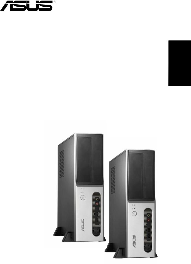
Pundit-PH3
Pundit-PE3
Barebone Systems
Quick Start Guide
English
English
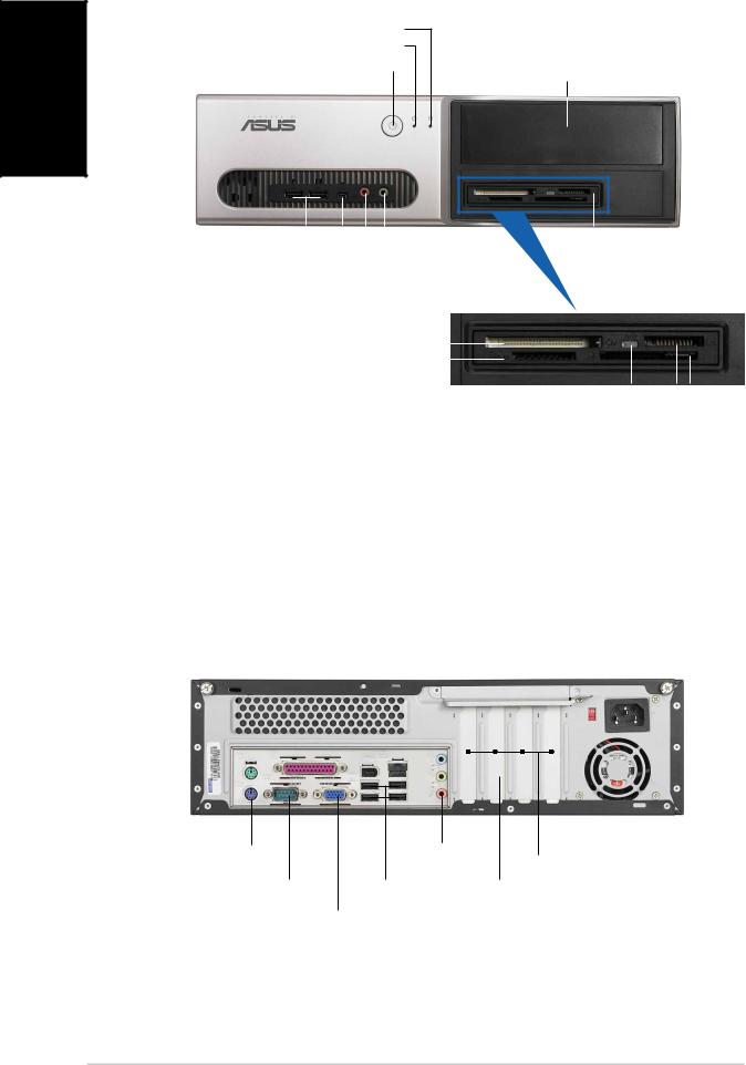
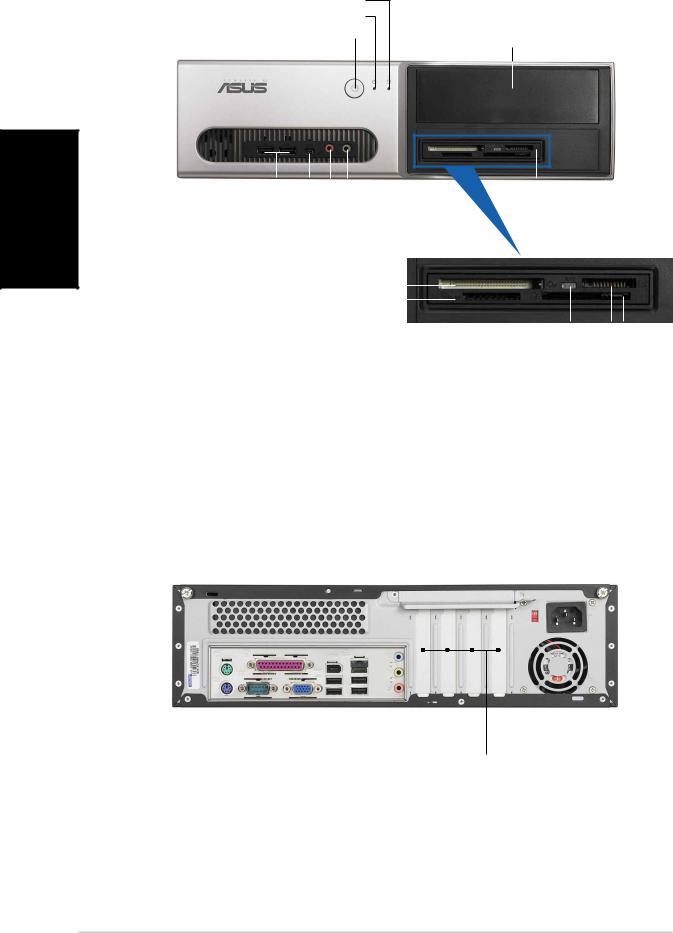
Front panel features
HD D LED |
|
Powe r LED |
|
Powe r button |
5.25-inch drive bay cover |
|
|
|
|
|
|
|
|
|
|
|
|
|
|
|
|
|
|
|
|
|
|
|
|
|
|
US B 2. 0 ports |
|
|
|
Microphone port |
6-in-1 card reader* |
||||||||||||||||||
4-pin IEEE 1394a port |
|
|
|
|
Headphone port |
|
|
|
|
|
|
|
|
|||||||||||
|
|
|
|
|
|
|
|
|
|
|
|
|||||||||||||
|
CompactFlash® car d slot |
|
|
|
|
|
|
|
|
|
|
|
|
|
||||||||||
|
|
|
|
|
|
|
|
|
|
|
|
|
|
|||||||||||
|
|
|
|
|
|
|
|
|
|
|
|
|
||||||||||||
Secure Digital™/MultimediaCard slot |
|
|
|
|
|
|
|
|
|
|
|
|
|
|||||||||||
|
|
|
|
|
|
|
|
|
|
|
|
|
||||||||||||
*Pundit-PH3 model only |
|
|
|
|
|
|
|
|
|
|
|
|
|
|
|
|
|
|
|
|||||
|
|
|
|
|
|
|
|
|
|
|
|
|
|
|
|
|
|
|
||||||
|
|
|
|
|
|
|
|
|
|
|
Card reader LED |
|
|
|||||||||||
|
|
|
|
|
|
|
|
|
|
|
Memor y Stick® /Pro™ card slot |
|
|
|
||||||||||
|
|
|
|
|
|
|
|
|
|
|
|
|
||||||||||||
|
|
|
|
|
|
|
|
|
|
|
|
|
|
SmartMedia® car d slot |
|
|
||||||||
|
|
|
|
|
|
|
|
|
|
|
|
|
|
|
|
|||||||||
Rear panel features |
|
|
|
|
|
|
|
|
||||||||||||||||
|
|
|
|
|
|
|
|
|
|
Paralle l port |
|
|
|
|
|
|
|
|
||||||
|
|
|
|
|
|
|
|
|
|
|
|
|
|
|
|
|
|
|||||||
|
|
|
|
|
|
|
|
|
|
Ai r vents |
|
|
|
|
|
|
|
|
||||||
|
|
|
|
|
|
|
|
|
|
|
|
|
|
|
|
|
|
|||||||
|
|
|
|
|
|
|
|
|
|
IEEE 1394a port |
Voltage selector |
|||||||||||||
|
|
|
|
|
|
|
|
|
|
|||||||||||||||
PS/2 mouse port |
|
|
|
|
|
LAN (RJ-45) port |
|
Power connector |
||||||||||||||||
Cove r screw |
|
|
|
|
|
|
|
|
|
Lin e I n port |
|
|||||||||||||
|
|
|
|
|
|
|
|
|
|
|
|
|
|
|
|
|
||||||||
|
|
|
|
|
|
|
|
|
|
|
|
|
|
|
|
|||||||||
|
|
|
|
|
|
|
|
|
|
|
Metal bracket lock |
|
|
|
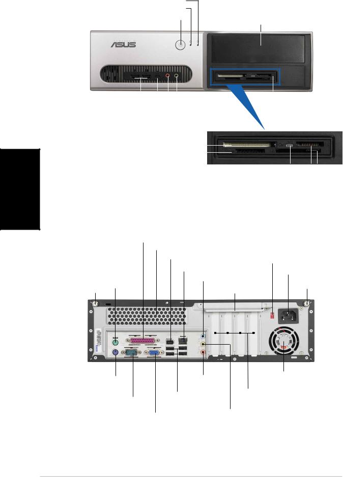
Cove r screw |
|||||||||
|
|
|
|
|
|
|
|
|
|
|
||||||||||||||
|
|
|
|
|
|
|
|
|
|
|
|
|
|
|
|
|
||||||||
|
|
|
|
|
|
|
|
|
|
|
|
|
|
|
|
|
|
|
|
|
|
|
|
|
|
|
|
|
|
|
|
|
|
|
|
|
|
|
|
|
|
|
|
|
|
|
|
|
|
|
|
|
|
|
|
|
|
|
|
|
|
|
|
|
|
|
|
|
|
|
|
|
|
|
|
|
|
|
|
|
|
|
|
|
|
|
|
|
|
|
|
|
|
|
|
|
|
|
|
|
|
|
|
|
|
|
|
|
|
|
|
|
|
|
|
|
|
|
|
|
|
|
|
|
|
|
|
|
|
|
|
|
|
|
|
|
|
|
|
|
|
|
|
|
|
|
|
|
|
|
|
|
|
|
|
|
|
|
|
|
|
|
|
|
|
|
|
|
|
|
|
|
|
|
|
|
|
|
|
|
|
|
|
|
|
|
|
|
|
|
|
|
|
|
|
|
|
|
|
|
Lin e Out |
Power fan vents |
|
PS/2 keyboard port |
PCI slot metal brackets |
||
p o r t |
|||
|
|||
|
|
||
Seria l port US B 2. 0 ports Microphone port |
|||
|
VG A port |
|
|
2 |
Quick Installation Guide |
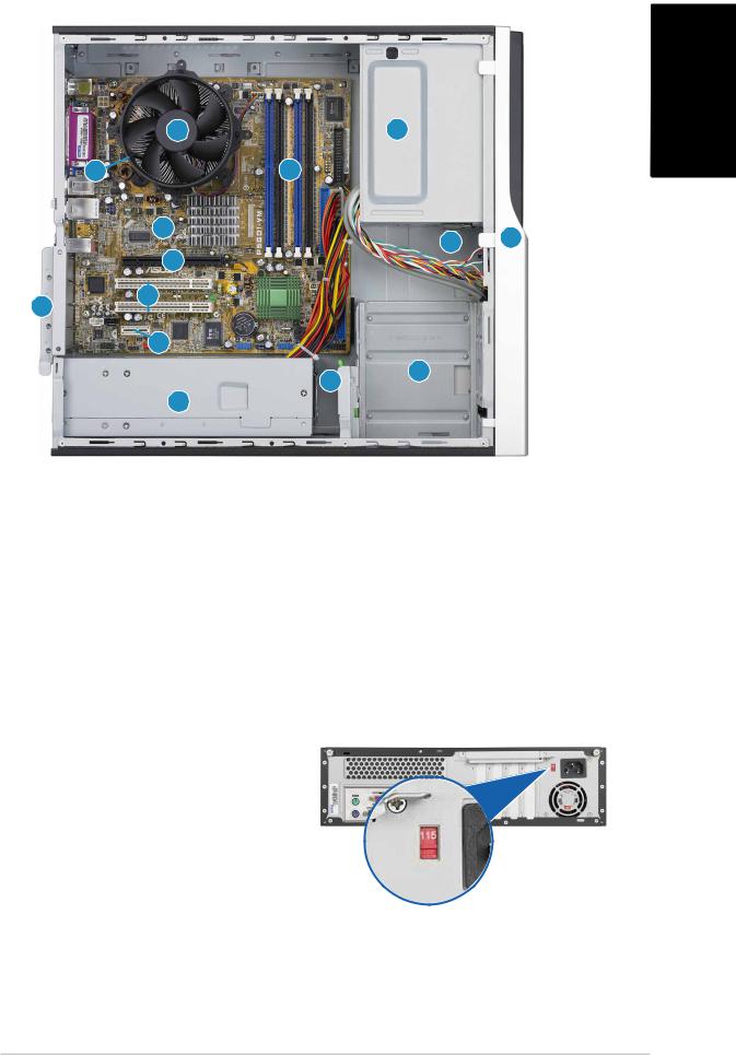
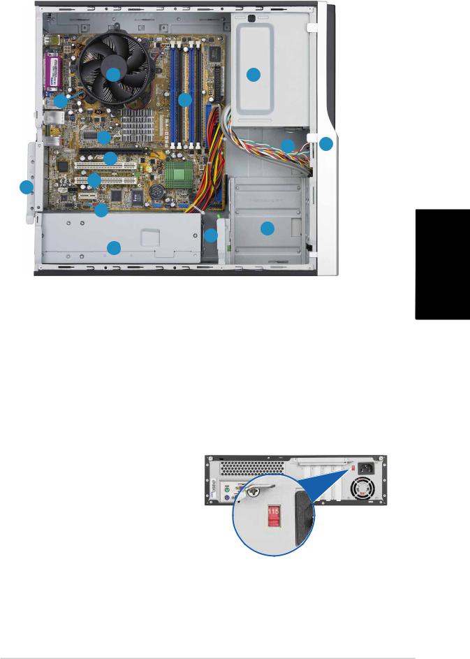
Internal components
13 |
1 |
|
12 |
14 |
|
10 |
3 |
2 |
|
|
9 |
|
11 |
8 |
|
|
|
|
|
7 |
|
|
5 |
4 |
|
|
|
|
6 |
|
1.5.25-inch empty optical drive bay
2.Front panel cover
3.Optical drive lock
4.Hard disk drive bays
5.Hard disk drive lock
6.Power supply unit
7.PCI Express x1 slot
8.PCI slots
Selecting the voltage
The system’s power supply unit has a 115 V/230 V voltage selector switch located beside the power connector. Use this switch to select the appropriate system input voltage according to the voltage supply in your area.
If the voltage supply in your area is 100-127 V, set the switch to 115 V.
If the voltage supply in your area is 200-240 V, set the switch to 230 V.
9.PCI Express x16 slot
(on Pundit-PH3 model only)
10.ASUS motherboard
11.Metal bracket lock
12.LGA775 socket (under the CPU fan and heatsink assembly)
13.CPU fan and heatsink assembly
14.DIMM sockets
English
Quick Installation Guide |
3 |
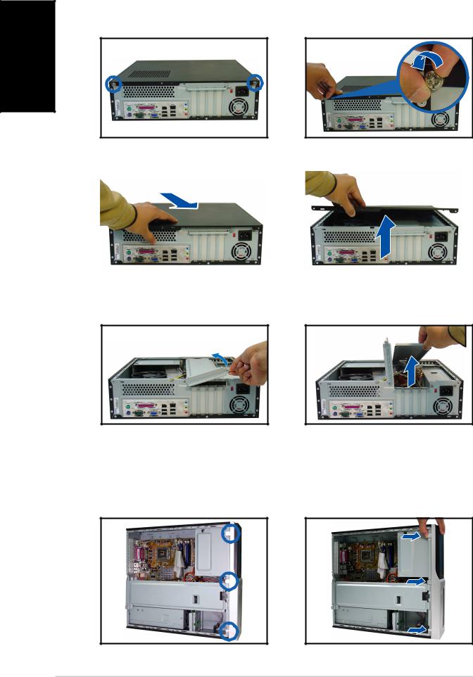
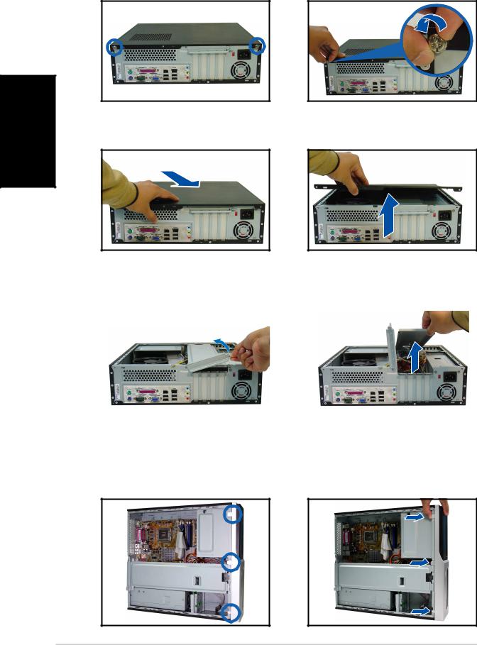
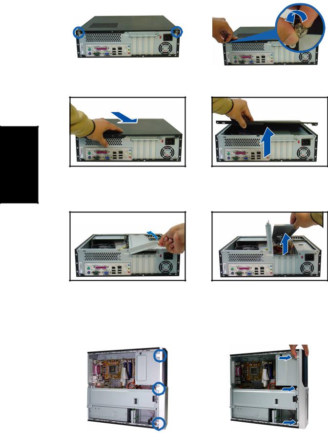
Removing the cover
1. Locate two cover screws. |
2. Remove the cover screws. |
English
3. Pull the cover. |
4. Lift the cover, then set aside. |
||
|
|
|
|
|
|
|
|
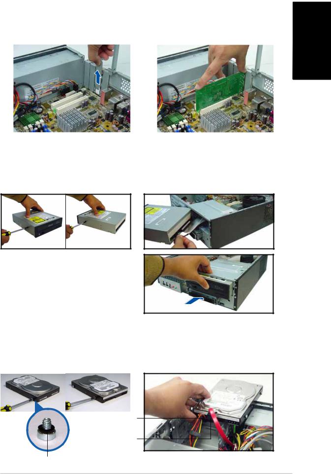
5.Lift the expansion card lock to a 90º-100º angle.
6.Lift the chassis support bracket, then remove.
Removing the front panel assembly
1.Locate the front panel assembly hooks.
2.Pull the hooks outward to remove.
4 |
Quick Installation Guide |

Installing a CPU
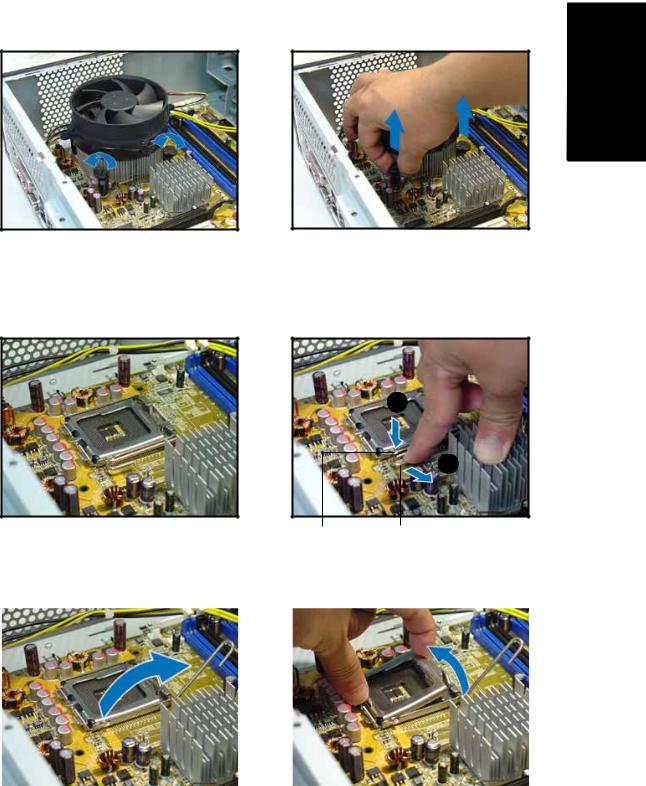
Removing the CPU fan and heatsink assembly
1. |
Disconnect the CPU fan cable. |
3. |
Pull two fasteners at a time to |
2. |
Rotate the fasteners |
|
remove the fan and heatsink. |
|
|
||
|
counterclockwise. |
4. |
After removing the fan, rotate |
|
|
|
each fastener clockwise. |
|
|
|
|
|
|
|
|
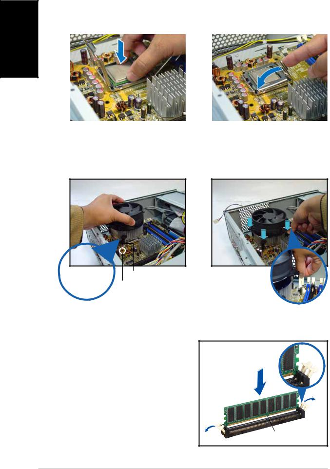
Installing the CPU
1. Locate the CPU socket. |
2. Unlock the load lever. |
A
B
|
|
Retentio n tab |
Loa d lever |
|
|
3. Lift the load lever. |
4. Lift the load plate. |
|
|||
|
|
|
|
|
|
|
|
|
|
|
|
|
|
|
|
|
|
English
Quick Installation Guide |
5 |
English
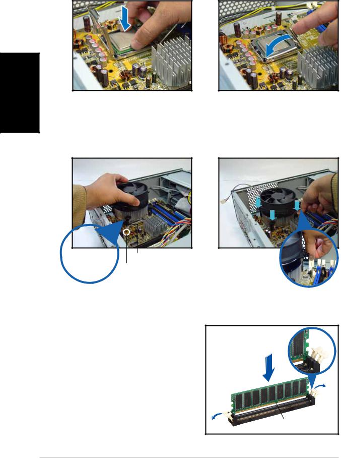
5. Install the CPU. |
6. Close the load plate, then lock |
|||
|
|
|
|
the load lever. |
|
|
|
|
|
|
|
|
|
|
|
|
|
|
|
|
|
|
|
|
Reinstalling the CPU fan and heatsink assembly
1.Place the heatsink on top of the installed CPU.
2.Push down the fasteners.
3.Connect the CPU fan cable.
Fastener Motherboard hole
 Narrow end of the groove
Installing a DIMM
1.Locate the DIMM sockets in the motherboard.
2.Unlock a DIMM socket by pressing the retaining clips outward.
3.Align a DIMM on the socket such that the notch on the DIMM
matches the break on the socket.
Unlocked retainin g clip
tch
6 |
Quick Installation Guide |
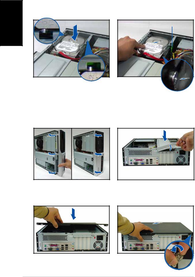
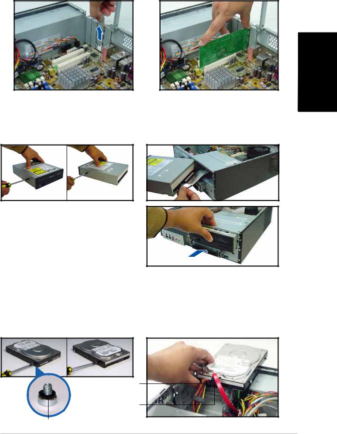
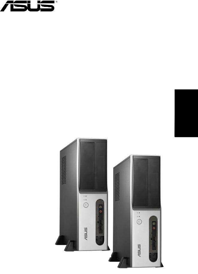
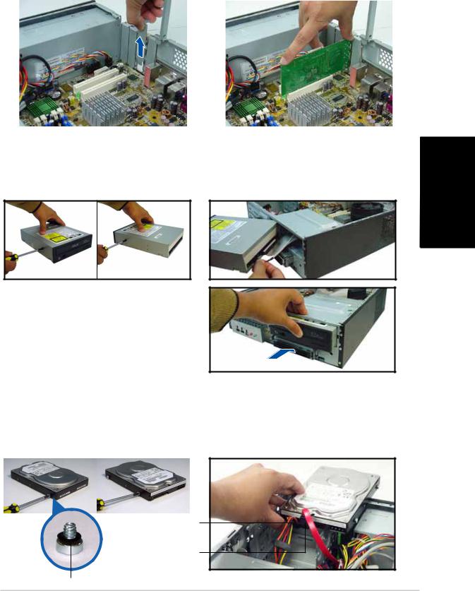
Installing an expansion card
1. Remove the metal cover |
2. Insert the card connector to |
||
|
opposite the slot that you |
|
the slot, then press the card |
|
intend to use. |
|
firmly until it fits in place. |
|
|
|
|
|
|
|
|
Installing an optical drive
1.Drive a screw on the top right screw hole on both sides of the drive.
3.Push the drive all the way into the bay until the drive lock clicks.
4.Connect a 4-pin power plug from the power supply unit to the power connector at the back of the drive.
2.Connect the IDE and audio cable at the back of the drive.
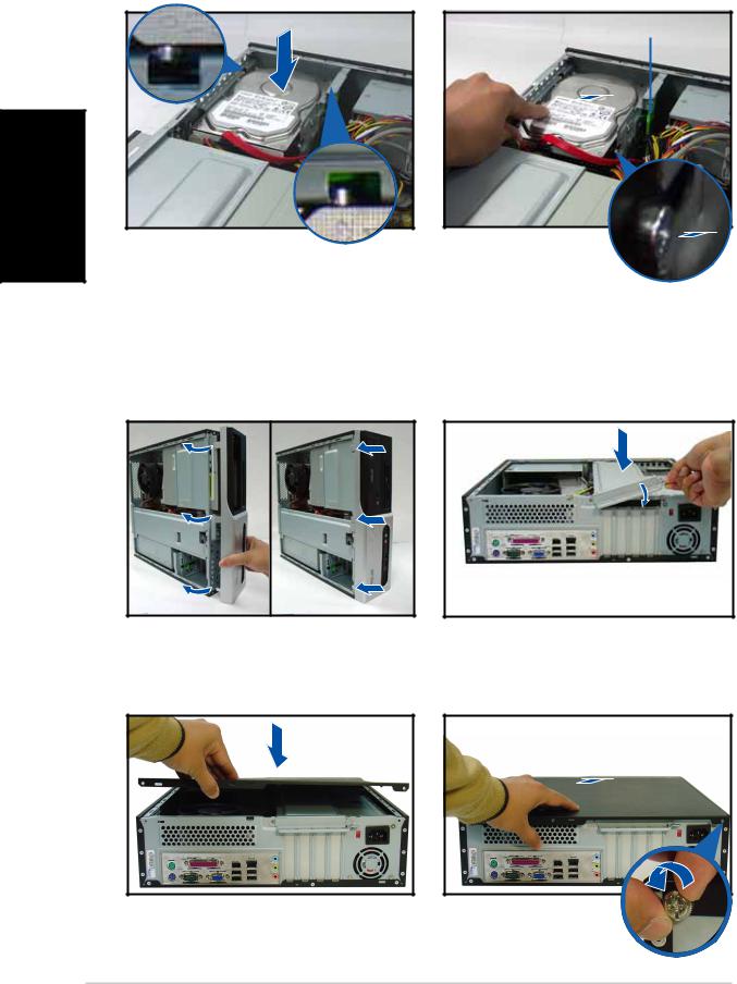
Installing a SATA hard disk drive
1. Drive two screws with rubber |
2. Connect the SATA signal and |
|
washers on both sides of the |
power plug at the back of the |
|
drive. |
drive. |
|
|
|
|
|
|
|
Powe r cable an d plug
Signa l cable an d plug
Rubbe r washer
English
Quick Installation Guide |
7 |
English
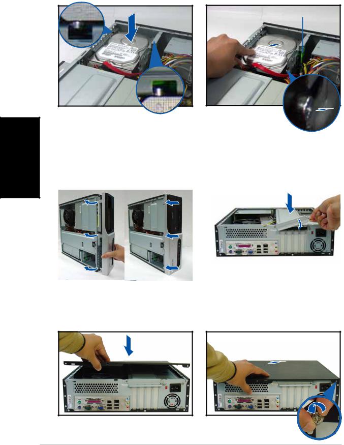
3.Place the HDD on the tray.
Replacing the covers
1.Replace the front panel assembly. Remove the 5.25” drive bay cover when you installed an optical drive.
3.Insert the cover hooks to the holes on the chassis side.
4.When the HDD screws align, push the drive on the bay.
HDD screw lock
2.Reinstall the metal chassis support and the expansion card lock.
4.Push the cover to the direction of the front panel, then replace the cover screws.
8 |
Quick Installation Guide |
Pundit-PH3 Pundit-PE3
Système barebone
Guide de démarrage rapide
Français
Caractéristiques de la façade
LE D HDD |
|
LED d’alimentation |
|
Bouton d’alimentation |
Cache de baie 5.25 pouces |
Français
|
|
|
|
|
|
|
|
|
|
|
|
|
|
|
|
|
|
|
|
|
|
|
|
|
|
Port s US B 2 . 0 |
|
|
|
Por t Microphone |
Lecteur de cartes |
||||||||||||||||||
Port IEEE 1394a 4 |
|
|
|
|
Por t Casque |
6 - en - 1* |
||||||||||||||||||
|
|
|
|
|||||||||||||||||||||
|
|
broches |
|
|
|
|
|
|
|
|
|
|
|
|
|
|
|
|
|
|
|
|||
Slot pour cartes CompactFlash® |
|
|
|
|
|
|
|
|
|
|
||||||||||||||
|
|
|
|
|
|
|
|
|
|
|
|
|||||||||||||
|
|
|
|
|
|
|
|
|
|
|
|
|||||||||||||
Slot Secure Digital™/MultimediaCard |
|
|
|
|
|
|
|
|
|
|
||||||||||||||
|
|
|
|
|
|
|
|
|
|
|
|
|||||||||||||
*Modèle Pundit-PH3 uniquement |
|
|
|
|
|
|
|
|
|
|
|
|
|
|
|
|
|
|
|
|||||
|
|
|
|
|
|
|
|
|
|
|
|
|
|
|
|
|
|
|
||||||
|
|
|
|
|
|
|
|
LED lecteur de cartes |
|
|
||||||||||||||
|
|
|
|
|
|
|
|
|
|
|
|
|
|
|
|
|||||||||
|
|
|
|
|
|
Slot pour cartes Memory Stick® / P r o ™ |
|
|
|
|||||||||||||||
|
|
|
|
|
|
|
|
|
||||||||||||||||
|
|
|
|
|
|
|
|
|
|
|
Slot pour cartes SmartMedia® |
|
|
|||||||||||
|
|
|
|
|
|
|
|
|
|
|
|
|
||||||||||||
Caractéristiques de l’arrière |
|
|
|
|
|
|
|
|
||||||||||||||||
|
|
|
|
|
|
|
|
|
|
Port parallèle |
|
|
|
|
|
|
|
|
||||||
|
|
|
|
|
|
|
|
|
|
|
|
|
|
|
|
|
|
|||||||
|
|
|
|
|
|
|
|
|
|
Aérations |
Sélecteur de tension |
|||||||||||||
|
|
|
|
|
|
|
|
|
|
|||||||||||||||
|
|
|
|
|
|
|
|
|
|
Port IEEE 1394a |
|
Connecteur |
||||||||||||
|
|
|
|
|
|
|
||||||||||||||||||
|
|
|
|
|
|
|
|
|
|
|
||||||||||||||
Port souris PS/2 |
|
|
|
|
|
|
Port LAN (RJ-45) |
|
||||||||||||||||
|
|
|
|
|
|
|
d’alimentation |
|||||||||||||||||
Vi s d u capot |
|
|
|
|
|
|
|
|
|
Por t Lin e In |
|
|
|
|
Vi s d u capot |
|||||||||
|
|
|
|
|
|
|
|
|||||||||||||||||
|
|
|
|
|
|
|
|
|
|
|
Verrouillage des |
|
|
|
|
|||||||||
|
|
|
|
|
|
|
|
|
|
|
||||||||||||||
|
|
|
|
|
|
|
|
|
|
|
|
|
|
|
|
|
||||||||
|
|
|
|
|
|
|
|
|
|
|
|
|
brackets métalliques |
|
|
|
|
|
|
|
||||
|
|
|
|
|
|
|
|
|
|
|
|
|
||||||||||||
|
|
|
|
|
|
|
|
|
|
|
|
|
|
|
|
|
|
|
|
|
|
|
|
|
|
|
|
|
|
|
|
|
|
|
|
|
|
|
|
|
|
|
|
|
|
|
|
|
|
|
|
|
|
|
|
|
|
|
|
|
|
|
|
|
|
|
|
|
|
|
|
|
|
|
|
|
|
|
|
|
|
|
|
|
|
|
|
|
|
|
|
|
|
|
|
|
|
|
|
|
|
|
|
|
|
|
|
|
|
|
|
|
|
|
|
|
|
|
|
|
|
|
|
|
|
|
|
|
|
|
|
|
|
|
|
|
|
|
|
|
|
|
|
|
|
|
|
|
|
|
|
|
|
|
|
|
|
|
|
|
|
|
|
|
|
|
|
|
|
|
|
|
|
|
|
|
|
|
|
|
|
|
|
|
|
|
|
|
|
|
|
|
|
|
|
|
|
|
|
|
|
|
|
|
|
|
|
|
|
|
|
|
|
|
|
|
|
|
|
|
|
|
|
Port clavier PS/2 |
|
|
|
|
Por t Line |
||
|
|
|
|
O u t |
|||
|
|
|
|
|
|
||
Por t Série |
|
|
|
|
|
||
|
|
|
Port s US B 2 . 0 Por t |
||||
|
|
|
|
|
|
|
|
|
|
Por t VGA |
|||||
Aération
d’alimentation Brackets métalliques des port s PCI
Microphone
2 |
Guide de démarrage rapide |
Composants internes
13 |
1 |
|
12 |
14 |
|
10 |
3 |
2 |
|
|
9 |
|
11 |
8 |
|
|
|
|
|
7 |
|
|
5 |
4 |
|
|
|
|
6 |
|
1. |
Baie 5.25 pouces vide |
9. |
Slot PCI Express x16 |
2. |
Façade |
|
(sur modèle Pundit-PH3 |
3. |
Verrouillage du lecteur optique |
|
uniquement) |
4. |
Baies pour disques durs |
10. |
Carte mère ASUS |
5. |
Verrouillage du disque dur |
11. |
Verrouillage des brackets |
6. |
Alimentation |
|
métalliques |
7. |
Slot PCI Express x1 |
12. |
Socket LGA775 (sous le système |
8. |
Slots PCI |
|
de refroidissement du CPU) |
|
|
13. |
Système de refroidissement du |
|
|
|
CPU |
|
|
14. |
Sockets DIMM |
Choisir le voltage
L’alimentation du système est équipée d’un sélecteur de tension 115 V/230 V situé près du connecteur d’alimentation. Utilisez cet interrupteur pour choisir la bonne tension d’entrée en fonction des standards utilisés dans votre région.
Si la tension dans votre région est de 100-127 V, passez l’interrupteur sur 115 V.
Si la tension dans votre région est de 200-240 V, passez l’interrupteur sur 230 V.
Français
Guide de démarrage rapide |
3 |
Français
Enlever le capot
1.Localisez les deux vis.
3.Tirez le capot.
2.Enlevez les deux vis.
4.Soulevez le capot, puis basculez-le.
5. Levez le verrou pour cartes |
6. Soulevez le support de |
|||
|
d’extension à un angle de 90º- |
|
brackets puis enlevez-le. |
|
100º. |
|
|
|
|
|
|
|
|
|
|
|
|
|
|
|
|
|
|
|
Enlever la façade
1.Localisez les crochets de la façade.
2.Tirez les crochets vers l’extérieur.
4 |
Guide de démarrage rapide |
Installer un CPU
Enlever le système de ventilation du CPU
1.Déconnectez le câble de ventilation du CPU.
2.Faites tourner les verrous dans le sens inverse des aiguilles d’une montre.
3.Tirez deux verrous à la fois pour enlever l’ensemble radiateur ventilateur.
4.Après avoir enlevé le ventilateur, faites tourner chaque verrou dans le sens des aiguilles d’une montre.
Français
Installer le CPU
1. Localisez le socket du CPU. |
2. Débloquez le levier. |
A
B
|
|
Onglet de rétention L e v i e r |
|
||
3. Soulevez le levier. |
|
4. Enlevez la plaque. |
|
||
|
|
|
|
|
|
|
|
|
|
|
|
|
|
|
|
|
|
Guide de démarrage rapide |
5 |
5. Installez le CPU. |
6. Refermez la plaque puis |
|
verrouillez le levier. |
Français
Réinstaller le système de ventilation
1. Placez le dissipateur sur le CPU |
2. |
Poussez sur les verrous. |
installé. |
3. |
Connectez le câble de |
|
ventilation du CPU.
V e r r o u
Trou de la carte mère
 Partie étroite
Installer un module DIMM
1.Localisez les sockets DIMM de la carte mère.
2.Déverrouillez un socket DIMM en pressant sur les clips de rétention vers l’extérieur.
3.Alignez un module DIMM sur le socket de sorte que l’encoche sur la DIMM corresponde à l’ergot du socket.
Clip de rétention déverrouillé
DR
6 |
Guide de démarrage rapide |
Installer une carte d’extension
1.Enlevez la protection métallique du slot que vous voulez utiliser.
2.Insérez le connecteur de la carte dans le slot et pressez jusqu’à ce que la carte soit en place.
Français
Installer un lecteur optique
1.Mettez une vis dans le pas de vis en haut à droite de chaque côté du lecteur.
3.Enfoncez le lecteur dans la baie jusqu’à ce que les verrous cliquent.
4.Branchez une prise d’alimentation 4 broches de l’alimentation dans le connecteur d’alimentation à l’arrière du lecteur.
2.Connectez les câbles IDE et audio à l’arrière du lecteur.
Installer un disque dur SATA
1.Mettez deux vis avec joint de caoutchouc de chaque côté du lecteur.
2.Connectez les câbles de signal et d’alimentation à l’arrière du disque.
Câble et prise d’alimentation
Câble et prise d e signal
Joint de caoutchouc
Guide de démarrage rapide |
7 |
3.Placez le disque dur sur le plateau.
Français
Refermer la machine
1.Replacez la façade. Enlevez le cache de la baie 5.25” si vous avez installé un lecteur optique.
3.Insérez les crochets dans les trous de chaque côté du châssis.
4.Quand les vis du disque sont alignées, poussez-le dans la baie.
Verrou des vis HDD
2.Réinstallez le support de châssis métallique et le verrouillage des cartes d’extension.
4.Poussez la plaque vers la façade, puis revissez le panneau.
8 |
Guide de démarrage rapide |
Pundit-PH3
Pundit-PE3
Barebone Systeme
Schnellinstallationsanleitung
Deutsch
Frontseite
HDD - LED
Betriebs - LED Blende des 5,25-Zoll
Stromschalter Laufwerkfachs
Deutsch
|
|
|
|
|
|
|
|
|
|
|
|
|
|
|
USB 2.0-Anschlüsse |
|
|
|
Mikrofonanschluss |
6-in-1 Kartenleser* |
|||||||||
4-pol. IEEE 1394a- |
|
|
|
Kopfhöreranschluss |
|
|
|
|
|
|
||||
|
|
|
|
|
|
|
|
|
||||||
Anschluss |
|
|
|
|
|
|
|
|
|
|
|
|
|
|
CompactFlash® -Kartensteckplatz |
|
|
|
|
|
|
|
|
||||||
|
|
|
|
|
|
|
|
|||||||
|
|
|
|
|
|
|
|
|||||||
Secure Digital™ MultimediaCard- |
|
|
|
|
|
|
|
|
||||||
|
|
|
|
|
|
|
|
|||||||
|
|
Steckplatz |
|
|
|
|
|
|
|
|||||
*Nur beim Pundit-PH3 Modell |
|
|
|
|
|
|
|
|
|
|
|
|
||
|
|
|
|
|
|
|
Kartenleser-LED |
|
|
|||||
|
|
|
Memor y Stick® P r oT M-Kartensteckplatz |
|
|
|
||||||||
|
|
|
|
|
|
|||||||||
|
|
|
|
|
|
SmartMedia® -Kartensteckplatz |
|
|
||||||
|
|
|
|
|
|
|
|
|||||||
Rückseite
|
|
|
|
|
|
Paralleler Anschluss |
|
|
|
|
|
|
|
|
|
|
|
|
|
|
|
Lüftungsöffnungen |
|
|
|
|
|
|
|
|
|
Abdeckungsschraube |
|
|
|
IEEE 1394a-Anschluss Spannungsschalter |
|||
|
|
|
|||||
|
|
|
|
|
|
LAN (RJ-45)-Anschluss |
Stromanschluss |
|
|
P S / 2 - |
|
|
|
Line In-Anschluss |
|
|
|
|
|
|
Abdeckungsschraube |
||
|
Mausanschluss |
|
|
|
Metallblendenriegel |
||
|
|
|
|
|
|
|
|
P S / 2 - |
Lin e Out - |
Netzteilgebläse- |
|
Lüftungsöffnungen |
|||
Anschluss |
|||
Tastaturanschluss |
|
||
|
PCI-Steckplatz- |
||
|
US B 2 . 0 - |
||
Serieller Anschluss |
Metallblenden |
||
Anschlüsse |
|||
|
|
VGA - Anschluss Mikrofonanschluss
2 |
Schnellinstallationsanleitung |
Interne Komponenten
13 |
1 |
|
12 |
14 |
|
10 |
3 |
2 |
|
||
9 |
|
|
11 |
8 |
|
7
4
5
6
1. |
Leeres 5,25-Zoll Fach für ein |
8. |
PCI-Steckplätze |
|
optisches Laufwerk |
9. |
PCI Express x16-Steckplatz |
2. |
Fronttafelabdeckung |
|
(nur beim Pundit-PH3 Modell) |
3. |
Riegel des optischen |
10. |
ASUS-Motherboard |
|
Laufwerks |
11. |
Metallblendenriegel |
4. |
Festplattenfach |
12. |
LGA775-Sockel (unter der |
5. |
Riegel des Festplattenfachs |
|
CPU-Lüfter-Kühlkörper-Einheit) |
6. |
Netzteil |
13. |
CPU-Lüfter-Kühlkörper-Einheit |
7. |
PCI Express x1-Steckplatz |
14. |
DIMM-Steckplätze |
Auswählen der Netzspannung
Das Netzteil ist mit einem 115V/ 230V-Spannungsschalter neben dem Stromanschluss ausgestattet. Verwenden Sie diesen Schalter, um die passende Systemeingangsspannung entsprechend Ihrem Stromversorgungssystem in Ihrer Region auszuwählen.
Stellen Sie den Schalter auf 115V, wenn die Stromversorgung in Ihrer Region 100V bis 127V ist.
Stellen Sie den Schalter auf 230V, wenn die Stromversorgung in Ihrer Region 200V bis 240V ist.
Deutsch
Schnellinstallationsanleitung |
3 |
Entfernen der Abdeckung
1. Suchen Sie die zwei |
2. Entfernen Sie die |
||
|
Abdeckungsschrauben. |
|
Abdeckungsschrauben. |
|
|
|
|
|
|
|
|
Deutsch
3.Ziehen Sie die Abdeckung.
5.Ziehen Sie den Erweiterungssteckplatzriegel bis zu einem Winkel von 90°- 100° hoch.
4.Heben Sie die Abdeckung und legen sie zur Seite.
6.Heben Sie das Gehäusestützblech, um es zu entfernen.
Entfernen der Fronttafeleinheit
1. Suchen Sie die |
2. Ziehen Sie die Haken nach |
||
|
Fronttafeleinheitshaken. |
|
außen, um die Einheit zu |
|
|
|
entfernen. |
|
|
|
|
|
|
|
|
|
|
|
|
4 |
Schnellinstallationsanleitung |
Installieren einer CPU
Entfernen der CPU-Lüfter-Kühlkörper-Einheit
1.Trennen Sie die Verbindung des CPU-Lüfterkabels.
2.Drehen Sie die Druckstifte gegen den Uhrzeigersinn.
3.Ziehen Sie auf einmal zwei Druckstifte, um den Lüfter und Kühlkörper zu entfernen.
4.Drehen Sie nach dem Entfernen des Lüfters jeden Druckstift im Uhrzeigersinn.
Installieren der CPU
1. Suchen Sie den CPU-Sockel. |
2. Entriegeln Sie den Arretierhebel. |
A
B
|
|
Halteriegel |
Arretierhebel |
|
|
3. Ziehen Sie den Arretierhebel |
4. Ziehen Sie den Deckrahmen |
|
|||
|
hoch. |
|
hoch. |
|
|
|
|
|
|
|
|
|
|
|
|
|
|
|
|
|
|
|
|
Deutsch
Schnellinstallationsanleitung |
5 |

5.Installieren Sie die CPU.
6.Schließen Sie den Deckrahmen und rasten dann den Arretierhebel ein.
Deutsch
Anbringen der CPU-Lüfter-Kühlkörper-Einheit
1. Legen Sie den Kühlkörper auf |
2. |
Drücken Sie die Druckstifte |
die installierte CPU. |
|
nach unten. |
|
3. |
Verbinden Sie das CPU- |
|
|
Lüfterkabel. |
|
|
|
|
|
|
Druckstift
Loch am Motherboard
 Enges Aussparungsende
Installieren eines DIMMs
1.Suchen Sie die DIMM-Steckplätze auf dem Motherboard.
2.Entriegeln Sie einen DIMMSteckplatz, indem Sie die Haltebügeln nach außen drücken.
3.Richten Sie ein DIMM auf den Steckplatz aus, wobei die Kerbe
am DIMM auf die Unterbrechung des Steckplatzes ausgerichtet werden muss.
Entriegelter
Haltebügel
rbe
6 |
Schnellinstallationsanleitung |
Installieren einer Erweiterungskarte
1. Entfernen Sie die Metallblende |
2. Stecken Sie die Karte mit der |
||
|
gegenüber dem Steckplatz, |
|
Kontaktseite nach unten in |
|
den Sie verwenden möchten. |
|
den Steckplatz ein und |
|
|
|
drücken dann fest nach unten, |
|
|
|
bis sie richtig sitzt. |
|
|
|
|
|
|
|
|
Installieren eines optischen Laufwerks
1.Drehen Sie eine Schraube in das obere rechte Schraubenloch an beiden Seiten des Laufwerks ein.
3.Schieben Sie das Laufwerk in das Fach ein, bis der Laufwerkriegel mit einem Klick-Ton einrastet.
4.Verbinden Sie einen 4-pol. Stromstecker von dem Netzteil mit dem Stromanschluss an der Rückseite des Laufwerks.
2.Verbinden Sie das IDEund das Audiokabel an der Rückseite des Laufwerks.
Installieren einer SATA-Festplatte
1. Drehen Sie zwei Schrauben mit |
2. Verbinden Sie den SATA-Signal- |
|||
|
Gummiunterlegscheibe an beiden |
und den Stromanschluss an der |
||
|
Seiten des Laufwerks ein. |
Rückseite des Laufwerks. |
||
|
|
|
|
|
|
|
|
|
|
Deutsch
Stromkabel un d - stecker
Signalkabel un d - stecker
Gummiunterlegscheibe
Schnellinstallationsanleitung |
7 |
3.Legen Sie die Festplatte in das Fach ein.
4.Schieben Sie das Laufwerk in das Fach hinein, wenn die Festplattenschrauben ausgerichtet sind.
Festplattenschraubenriegel
Deutsch
Anbringen der Abdeckungen
1. Bringen Sie die Fronttafeleinheit |
2. Bringen Sie das |
||
an. Entfernen Sie die 5,25" |
Gehäusestützblech und den |
||
Laufwerkfachblende, wenn Sie |
Erweiterungssteckplatzriegel |
||
ein optisches Laufwerk installiert |
wieder an. |
||
haben. |
|
||
|
|
|
|
|
|
|
|
3.Stecken Sie die Abdeckungshaken in die Löcher an der Seite des Gehäuses ein.
4.Drücken Sie die Abdeckung in Richtung der Fronttafel und bringen die Abdeckungsschrauben wieder an.
8 |
Schnellinstallationsanleitung |
 Loading...