


ASUS Pro WS C246-Ace Service Manual
Pro WS C246-ACE
Motherboard

E15411
First Edition
May 2019
Copyright © 2019 ASUSTeK COMPUTER INC. All Rights Reserved.
No part of this manual, including the products and software described in it, may be reproduced, transmitted, transcribed, stored in a retrieval system, or translated into any language in any form or by any means, except documentation kept by the purchaser for backup purposes, without the express written permission of ASUSTeK COMPUTER INC. (“ASUS”).
Product warranty or service will not be extended if: (1) the product is repaired, modified or altered, unless such repair, modification of alteration is authorized in writing by ASUS; or (2) the serial number of the product is defaced or missing.
ASUS PROVIDES THIS MANUAL “AS IS” WITHOUT WARRANTY OF ANY KIND, EITHER EXPRESS OR IMPLIED, INCLUDING BUT NOT LIMITED TO THE IMPLIED WARRANTIES OR CONDITIONS OF MERCHANTABILITY OR FITNESS FOR A PARTICULAR PURPOSE. IN NO EVENT SHALL ASUS, ITS DIRECTORS, OFFICERS, EMPLOYEES OR AGENTS BE LIABLE FOR ANY INDIRECT, SPECIAL, INCIDENTAL, OR CONSEQUENTIAL DAMAGES (INCLUDING DAMAGES FOR LOSS OF PROFITS, LOSS OF BUSINESS, LOSS OF USE OR DATA, INTERRUPTION OF BUSINESS AND THE LIKE), EVEN IF ASUS HAS BEEN ADVISED OF THE POSSIBILITY OF SUCH DAMAGES ARISING FROM ANY DEFECT OR ERROR IN THIS MANUAL OR PRODUCT.
SPECIFICATIONS AND INFORMATION CONTAINED IN THIS MANUAL ARE FURNISHED FOR INFORMATIONAL USE ONLY, AND ARE SUBJECT TO CHANGE AT ANY TIME WITHOUT NOTICE, AND SHOULD NOT BE CONSTRUED AS A COMMITMENT BY ASUS. ASUS ASSUMES NO RESPONSIBILITY OR LIABILITY FOR ANY ERRORS OR INACCURACIES THAT MAY APPEAR IN THIS MANUAL, INCLUDING THE PRODUCTS AND SOFTWARE DESCRIBED IN IT.
Products and corporate names appearing in this manual may or may not be registered trademarks or copyrights of their respective companies, and are used only for identification or explanation and to the owners’ benefit, without intent to infringe.
Offer to Provide Source Code of Certain Software
This product contains copyrighted software that is licensed under the General Public License (“GPL”), under the Lesser General Public License Version (“LGPL”) and/or other Free Open Source Software Licenses. Such software in this product is distributed without any warranty to the extent permitted by the applicable law. Copies of these licenses are included in this product.
Where the applicable license entitles you to the source code of such software and/or other additional data, you may obtain it for a period of three years after our last shipment of the product, either
(1)for free by downloading it from https://www.asus.com/support/
or
(2)for the cost of reproduction and shipment, which is dependent on the preferred carrier and the location where you want to have it shipped to, by sending a request to:
ASUSTeK Computer Inc.
Legal Compliance Dept.
15 Li Te Rd.,
Beitou, Taipei 112
Taiwan
In your request please provide the name, model number and version, as stated in the About Box of the product for which you wish to obtain the corresponding source code and your contact details so that we can coordinate the terms and cost of shipment with you.
The source code will be distributed WITHOUT ANY WARRANTY and licensed under the same license as the corresponding binary/object code.
This offer is valid to anyone in receipt of this information.
ASUSTeK is eager to duly provide complete source code as required under various Free Open Source Software licenses. If however you encounter any problems in obtaining the full corresponding source code we would be much obliged if you give us a notification to the email address gpl@asus.com, stating the product and describing the problem (please DO NOT send large attachments such as source code archives, etc. to this email address).
ii

Contents
Safety information...................................................................................................... |
iv |
About this guide.......................................................................................................... |
iv |
Package contents....................................................................................................... |
vi |
ASUS Pro WS C246-ACE specifications summary.................................................. |
vi |
Chapter 1: |
Product Introduction |
|
|
1.1 |
Before you proceed.................................................................................... |
1-1 |
|
1.2 |
Motherboard overview............................................................................... |
1-1 |
|
1.3 |
Central Processing Unit (CPU)................................................................ |
1-11 |
|
1.4 |
System memory........................................................................................ |
1-12 |
|
Chapter 2: |
BIOS Information |
|
|
2.1 |
Managing and updating your BIOS |
...........................................................2-1 |
|
2.2 |
BIOS setup program................................................................................... |
2-4 |
|
2.3 |
Exit menu |
..................................................................................................... |
2-9 |
Appendix |
|
|
|
Notices |
..................................................................................................................... |
|
A-1 |
iii

Safety information
Electrical safety
•To prevent electrical shock hazard, disconnect the power cable from the electrical outlet before relocating the system.
•When adding or removing devices to or from the system, ensure that the power cables for the devices are unplugged before the signal cables are connected. If possible, disconnect all power cables from the existing system before you add a device.
•Before connecting or removing signal cables from the motherboard, ensure that all power cables are unplugged.
•Seek professional assistance before using an adapter or extension cord. These devices could interrupt the grounding circuit.
•Ensure that your power supply is set to the correct voltage in your area. If you are not sure about the voltage of the electrical outlet you are using, contact your local power company.
•If the power supply is broken, do not try to fix it by yourself. Contact a qualified service technician or your retailer.
Operation safety
•Before installing the motherboard and adding devices on it, carefully read all the manuals that came with the package.
•Before using the product, ensure all cables are correctly connected and the power cables are not damaged. If you detect any damage, contact your dealer immediately.
•To avoid short circuits, keep paper clips, screws, and staples away from connectors, slots, sockets and circuitry.
•Avoid dust, humidity, and temperature extremes. Do not place the product in any area where it may become wet.
•Place the product on a stable surface.
•If you encounter technical problems with the product, contact a qualified service technician or your retailer.
About this guide
This user guide contains the information you need when installing and configuring the motherboard.
How this guide is organized
This guide contains the following parts:
•Chapter 1: Product Introduction
This chapter describes the features of the motherboard and the new technology it supports. It includes descriptions of the switches, jumpers, and connectors on the motherboard.
•Chapter 2: BIOS Information
This chapter discusses changing system settings through the BIOS Setup menus.
iv
Where to find more information
Refer to the following sources for additional information and for product and software updates.
1.ASUS website
The ASUS website (www.asus.com) provides updated information on ASUS hardware and software products.
2.Optional documentation
Your product package may include optional documentation, such as warranty flyers, that may have been added by your dealer. These documents are not part of the standard package.
Conventions used in this guide
To ensure that you perform certain tasks properly, take note of the following symbols used throughout this manual.
DANGER/WARNING: Information to prevent injury to yourself when trying to complete a task.
CAUTION: Information to prevent damage to the components when trying to complete a task.
IMPORTANT: Instructions that you MUST follow to complete a task.
NOTE: Tips and additional information to help you complete a task.
Typography
Bold text |
Indicates a menu or an item to select. |
Italics |
Used to emphasize a word or a phrase. |
<Key> |
Keys enclosed in the less-than and greater-than sign |
|
means that you must press the enclosed key. |
|
Example: <Enter> means that you must press the Enter or |
|
Return key. |
<Key1> + <Key2> + <Key3> |
If you must press two or more keys simultaneously, the key |
|
names are linked with a plus sign (+). |
v

Package contents
Check your motherboard package for the following items.
Motherboard |
1 x ASUS Pro WS C246-ACE Motherboard |
Cables |
2 x Serial ATA 6.0Gb/s Cables |
|
1 x I/O Shield |
Accessories |
1 x M.2 Screw Package |
|
1 x ACC Activation Key Card |
Application DVD |
1 x Support DVD |
Documentation |
1 x User manual |
If any of the above items is damaged or missing, contact your retailer.
ASUS Pro WS C246-ACE specifications summary
|
Socket 1151 for Intel® Xeon® processor E-2200/E-2100 family, Intel® Pentium™ |
|
|
processors, Intel® Celeron™ processors, Intel® Core™ i9/i7/i5/i3 processors* |
|
CPU |
Supports 14nm CPU |
|
Supports Intel® Turbo Boost Technology 2.0** |
||
|
||
|
* Refer to www.asus.com for Intel® CPU support list. |
|
|
** The Intel® Turbo Boost Technology 2.0 support depends on the CPU types. |
|
Chipset |
Intel® C246 Chipset |
|
|
4 x DIMM, Max. 128GB, DDR4 2666/2400/2133 MHz ECC Memory |
|
|
Dual channel memory architecture |
|
Memory |
Supports Intel® Extreme Memory Profile (XMP) |
|
* The maximum memory frequency supported varies by processor. |
||
|
||
|
* DDR4 2666MHz and higher memory modules will run at max. 2666MHz on Intel® 8th |
|
|
Gen. 6-core or higher processors. |
|
|
* Refer to www.asus.com for the Memory QVL (Qualified Vendors List). |
|
|
|
|
Expansion |
2 x PCIe 3.0/2.0 x16 slots (supports x16 or x8/x8) |
|
1 x PCIe 3.0/2.0 x16 slot (max. at x2 mode) |
||
slots |
||
2 x PCIe 3.0/2.0 x1 slots |
||
|
||
Multi-GPU |
Supports AMD® 2-Way CrossFireX™ Technology |
|
Support |
||
|
||
|
|
|
|
Integrated Graphics ProcessorIntel® UHD Graphics support |
|
|
Multi-VGA output support : HDMI/DisplayPort ports |
|
VGA |
- Supports HDMI 1.4 with max. resolution up to 4096x2160@24 Hz / |
|
2560x1600@60Hz |
||
|
||
|
- Supports DisplayPort 1.2 with max. resolution up to 4096x2160 @ 60Hz |
|
|
Maximum shared memory of 2048 MB (for iGPU exclusively) |
|
|
(continued on the next page) |
vi

ASUS Pro WS C246-ACE specifications summary
|
Intel® C246 Chipset with RAID 0, 1, 5, 10 and Intel Rapid Storage Technology |
|
support |
|
- 1 x M.2_1 Socket 3 with M Key, type 2242/2260/2280/22110 storage devices |
|
support (PCIE x4 mode) |
Storage |
- 1 x M.2_2 Socket 3 with M Key, type 2242/2260/2280/22110 storage devices |
|
support (both SATA & PCIE x2 mode) |
|
- 1 x U.2 Socket |
|
- 4 x SATA 6.0 Gb/s ports |
|
- Ready for Intel® Optane Memory |
|
1 x Intel® I210AT |
|
1 x i219-LM |
LAN |
Wake on LAN |
|
ASUS LANGuard |
|
Turbo LAN |
|
Realtek® S1220A 8-Channel High Definition Audio CODEC |
-Power pre-regulator reduces power input noise to ensure consistent performance
-Impedance sense for front and rear headphone outputs
-Internal audio Amplifier to enhance the highest quality sound for headphone and speakers
-Supports : Jack-detection, Multi-streaming, Front Panel Jack-retasking
|
|
Audio Feature: |
|
|
Audio |
- Optical S/PDIF out port(s) at back panel |
|
|
|
|
|
|
|
- Audio Shielding: Ensures precision analog/digital separation and greatly reduced |
|
|
|
multi-lateral interference |
|
|
|
- Dedicated audio PCB layers: Separate layers for left and right channels to guard the |
|
|
|
quality of the sensitive audio signals |
|
|
|
- Premium Japanese-made audio capacitors: Provide warm, natural and immersive |
|
|
|
sound with exceptional clarity and fidelity |
|
|
|
- Unique de-pop circuit: Reduces start-up popping noise to audio outputs |
|
|
|
Intel® C246 Chipset |
|
|
USB |
- 4 x USB 3.2 Gen 2 ports (4 ports @back panel, 3x type A; 1x type C) |
|
|
- 6 x USB 3.2 Gen 1 ports (2 ports @mid-board; 4 ports @back panel) |
|
|
|
|
|
|
|
|
- 4 x USB 2.0 ports (4 ports @mid-board) |
|
|
|
(continued on the next page) |
|
vii

ASUS Pro WS C246-ACE specifications summary
ASUS 5X PROTECTION III
-ASUS SafeSlot Core: Fortified PCIe with solid soldering
-ASUS ESD Guard: Enhanced ESD protection
-ASUS Overvoltage Protection: World-class circuit-protecting power design
-ASUS Stainless-Steel Back I/O: 3X corrosion-resistance for greater durability!
-ASUS DIGI+ VRM power design
|
|
ASUS EPU |
|
|
|
- EPU |
|
|
|
ASUS Quiet Thermal Solution: |
|
|
|
- Stylish Fanless Design Heat-sink solution & MOS Heatsink |
|
|
Special |
- ASUS Fan Xpert 4 |
|
|
Features |
ASUS Exclusive Features |
|
|
|
- ASUS Ai Charger |
|
|
|
- ASUS AI Suite 3 |
|
|
|
ASUS EZ DIY |
|
|
|
- ASUS UEFI BIOS EZ Mode |
|
|
|
- ASUS CrashFree BIOS 3 |
|
|
|
- ASUS EZ Flash 3 |
|
|
|
ASUS Q-Design |
|
|
|
- ASUS Q-DIMM |
|
|
|
- ASUS Q-Slot |
|
|
|
- ASUS Q-LED (CPU, DRAM, VGA, Boot Device LED) |
|
|
|
1 x DisplayPort port |
|
|
|
1 x HDMI port |
|
|
|
2 x LAN (RJ45) port |
|
|
Back Panel |
3 x USB 3.2 Gen 2 (teal blue) Type-A |
|
|
I/O Ports |
1 x USB 3.2 Gen 2 USB Type-C |
|
|
|
4 x USB 3.2 Gen 1 ports |
|
|
|
1 x Optical S/PDIF out |
|
|
|
5 x Audio jack(s) |
|
|
|
(continued on the next page) |
|
viii

ASUS Pro WS C246-ACE specifications summary
|
1 x USB 3.2 Gen 1 connectors support additional 2 USB ports (19-pin) |
|
|
2 x USB 2.0 connectors support additional 4 USB ports |
|
|
1 x M.2_1 Socket 3 (for M Key, type 2242/2260/2280/22110 devices) |
|
|
1 x M.2_2 Socket 3 (for M Key, type 2242/2260/2280/22110 devices) |
|
|
1 x U.2 Socket |
|
|
4 x SATA 6.0Gb/s connectors |
|
|
1 x CPU Fan connector (support DC/PWM mode) |
|
|
1 x CPU_OPT connector (support DC/PWM mode) |
|
|
1 x AIO_PUMP header |
|
Internal I/O |
3 x Chassis Fan connectors (4-pin) for both 3-pin(DC mode) and 4-pin(PWM |
|
mode) coolers control |
||
Connectors |
||
1 x Front panel audio connector (AAFP) |
||
|
||
|
1 x 24-pin EATX Power connector |
|
|
1 x 8-pin EATX 12V Power connector |
|
|
1 x System Panel* |
|
|
1 x COM port |
|
|
1 x Node |
|
|
1 x Debug Header |
|
|
1 x Clear CMOS jumper |
|
|
1 x T_SENSOR |
|
|
* Chassis intrusion header is built in the system panel connector. |
|
|
|
|
|
128 Mb Flash ROM, UEFI AMI BIOS, PnP, SM BIOS 3.1, ACPI 6.1, Multi- |
|
BIOS |
language BIOS, ASUS EZ Flash 3, CrashFree BIOS 3, F11 EZ Tuning Wizard, |
|
F6 Qfan Control, F3 My Favorites, Last Modified log, F9 Search, F12 PrintScreen, |
||
|
||
|
and ASUS DRAM SPD (Serial Presence Detect) memory information |
|
Manageability |
WfM 2.0, DMI 3.0, WOL by PME, PXE |
|
|
2 x SATA 6Gb/s cables |
|
|
1 x IO Shield |
|
Accessories |
1 x M.2 Screw Package |
|
|
1 x Support DVD |
|
|
1 x User’s manual |
|
|
Drivers |
|
Support DVD |
ASUS Utilities |
|
ASUS EZ Update |
||
|
||
|
Anti-virus software (OEM version) |
|
OS Support |
Windows® 10 (64-bit) |
|
Form factor |
ATX Form Factor, 12”x 9.6” (30.5 cm x 24.4 cm) |
Specifications are subject to change without notice.
ix

x

Product Introduction |
1 |
1.1Before you proceed
Take note of the following precautions before you install motherboard components or change any motherboard settings.
• Unplug the power cord from the wall socket before touching any component.
•Before handling components, use a grounded wrist strap or touch a safely grounded object or a metal object, such as the power supply case, to avoid damaging them due to static electricity.
•Before you install or remove any component, ensure that the ATX power supply is switched off or the power cord is detached from the power supply. Failure to do so may cause severe damage to the motherboard, peripherals, or components.
1.2Motherboard overview
Place this side towards the rear of the chassis
Unplug the power cord before installing or removing the motherboard. Failure to do so can cause you physical injury and damage motherboard components.
ASUS Pro WS C246-ACE |
1-1 |
1.2.1Layout contents
Connectors/Jumpers/Slots |
Page |
|
1. |
ATX power connectors (24-pin EATXPWR, 8-pin EATX12V) |
1-2 |
2. |
Intel® LGA1151 CPU socket |
1-3 |
3. |
CPU, CPU optional, chassis, and AIO pump fan connectors (4-pin CPU_FAN, 4-pin |
1-3 |
|
CPU_OPT, 4-pin CHA_FAN1~3, 4-pin AIO_PUMP FAN) |
|
|
|
|
4. |
DDR4 DIMM slots |
1-3 |
5. |
USB 3.2 Gen 1 connector (20-1 pin U32G1_56) |
1-3 |
6. |
SATA 6Gb/s connector (7-pin SATA6G_1-4) |
1-4 |
7. |
Mini-SAS HD connector (U.2) |
1-4 |
8. |
System panel connector (20-3 pin PANEL) |
1-4 |
9. |
Clear RTC RAM (2-pin CLRTC) |
1-5 |
10. |
Thermal Sensor connector (2-pin T_SENSOR) |
1-5 |
11. |
USB 2.0 connector (10-1 pin USB1112; USB1314) |
1-5 |
12. |
Node connector (12-1 pin NODE) |
1-5 |
13. |
Serial port connector (10-1 pin COM) |
1-6 |
14. |
Front panel audio connector (10-1 pin AAFP) |
1-6 |
15. |
PCI Express 3.0/2.0 x16 slots |
1-6 |
16. |
PCI Express 3.0/2.0 x1 slots |
1-6 |
17. |
M.2 sockets (M.2_1(SOCKET3); M.2_2 (SOCKET3)) |
1-6 |
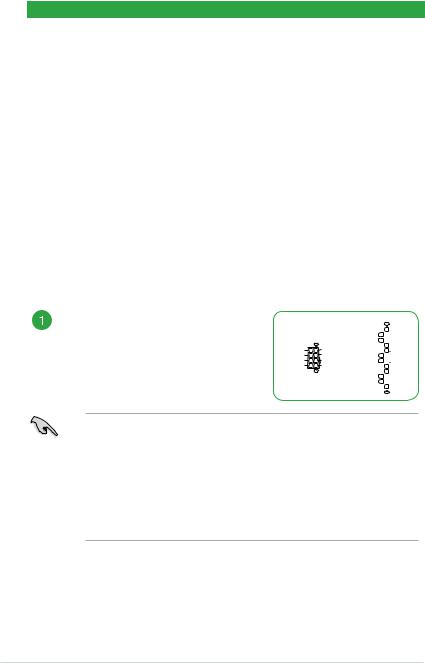
ATX power connectors (24-pin EATXPWR, 8-pin EATX12V)
Correctly orient the ATX power supply plugs into these connectors and push down firmly until the connectors completely fit.
EATX12V
GND |
+12V DC |
GND |
+12V DC |
GND |
+12V DC |
GND |
+12V DC |
PIN 1 |
|
EATXPWR
+3 |
Volts |
|
|
GND |
+12 |
Volts |
|
|
+5 Volts |
+12 |
Volts |
|
|
+5 Volts |
+5V Standby |
|
|
+5 Volts |
|
Power OK |
|
|
-5 Volts |
|
|
GND |
|
|
GND |
+5 |
Volts |
|
|
GND |
|
GND |
|
|
GND |
+5 Volts |
|
|
PSON# |
|
|
GND |
|
|
GND |
+3 |
Volts |
|
|
-12 Volts |
+3 |
Volts |
|
|
+3 Volts |
|
PIN 1 |
|
|
|
•The 8-pin Power Plug LED lights up to indicate that the 8-pin power plug is not connected.
•For a fully configured system, we recommend that you use a power supply unit (PSU) that complies with ATX 12 V Specification 2.0 (or later version) and provides a minimum power of 350 W. This PSU type has 24-pin and 8-pin power plugs.
•We recommend that you use a PSU with higher power output when configuring a system with more power-consuming devices or when you intend to install additional devices. The system may become unstable or may not boot up if the power is inadequate.
1-2 |
Chapter 1: Product Introduction |
 Loading...