


Asus P8H67-I PRO User Manual

P8H67-I Series
• P8H67-I PRO
• P8H67-I DELUXE
Motherboard

E6964
First Edition (V1)
November 2011
Copyright © 2011 ASUSTeK Computer Inc. All Rights Reserved.
No part of this manual, including the products and software described in it, may be reproduced,
transmitted, transcribed, stored in a retrieval system, or translated into any language in any form or by any
means, except documentation kept by the purchaser for backup purposes, without the express written
permission of ASUSTeK Computer Inc. (“ASUS”).
Product warranty or service will not be extended if: (1) the product is repaired, modied or altered, unless
such repair, modication of alteration is authorized in writing by ASUS; or (2) the serial number of the
product is defaced or missing.
ASUS PROVIDES THIS MANUAL “AS IS” WITHOUT WARRANTY OF ANY KIND, EITHER EXPRESS
OR IMPLIED, INCLUDING BUT NOT LIMITED TO THE IMPLIED WARRANTIES OR CONDITIONS OF
MERCHANTABILITY OR FITNESS FOR A PARTICULAR PURPOSE. IN NO EVENT SHALL ASUS, ITS
DIRECTORS, OFFICERS, EMPLOYEES OR AGENTS BE LIABLE FOR ANY INDIRECT, SPECIAL,
INCIDENTAL, OR CONSEQUENTIAL DAMAGES (INCLUDING DAMAGES FOR LOSS OF PROFITS,
LOSS OF BUSINESS, LOSS OF USE OR DATA, INTERRUPTION OF BUSINESS AND THE LIKE),
EVEN IF ASUS HAS BEEN ADVISED OF THE POSSIBILITY OF SUCH DAMAGES ARISING FROM ANY
DEFECT OR ERROR IN THIS MANUAL OR PRODUCT.
SPECIFICATIONS AND INFORMATION CONTAINED IN THIS MANUAL ARE FURNISHED FOR
INFORMATIONAL USE ONLY, AND ARE SUBJECT TO CHANGE AT ANY TIME WITHOUT NOTICE,
AND SHOULD NOT BE CONSTRUED AS A COMMITMENT BY ASUS. ASUS ASSUMES NO
RESPONSIBILITY OR LIABILITY FOR ANY ERRORS OR INACCURACIES THAT MAY APPEAR IN THIS
MANUAL, INCLUDING THE PRODUCTS AND SOFTWARE DESCRIBED IN IT.
Products and corporate names appearing in this manual may or may not be registered trademarks or
copyrights of their respective companies, and are used only for identication or explanation and to the
owners’ benet, without intent to infringe.
Offer to Provide Source Code of Certain Software
This product may contain copyrighted software that is licensed under the General Public License (“GPL”)
and under the Lesser General Public License Version (“LGPL”). The GPL and LGPL licensed code in this
product is distributed without any warranty. Copies of these licenses are included in this product.
You may obtain the complete corresponding source code (as dened in the GPL) for the GPL Software,
and/or the complete corresponding source code of the LGPL Software (with the complete machinereadable “work that uses the Library”) for a period of three years after our last shipment of the product
including the GPL Software and/or LGPL Software, which will be no earlier than December 1, 2011, either
(1) for free by downloading it from http://support.asus.com/download;
or
(2) for the cost of reproduction and shipment, which is dependent on the preferred carrier and the location
where you want to have it shipped to, by sending a request to:
ASUSTeK Computer Inc.
Legal Compliance Dept.
15 Li Te Rd.,
Beitou, Taipei 112
Taiwan
In your request please provide the name, model number and version, as stated in the About Box of the
product for which you wish to obtain the corresponding source code and your contact details so that we
can coordinate the terms and cost of shipment with you.
The source code will be distributed WITHOUT ANY WARRANTY and licensed under the same license as
the corresponding binary/object code.
This offer is valid to anyone in receipt of this information.
ASUSTeK is eager to duly provide complete source code as required under various Free Open Source
Software licenses. If however you encounter any problems in obtaining the full corresponding source code
we would be much obliged if you give us a notication to the email address gpl@asus.com, stating the
product and describing the problem (please do NOT send large attachments such as source code archives
etc to this email address).
ii

Contents
Notices ......................................................................................................... vi
Safety information ..................................................................................... vii
About this guide ....................................................................................... viii
P8H67-I Series specications summary ................................................... ix
Chapter 1: Product introduction
1.1 Before you proceed ..................................................................... 1-1
1.2 Motherboard overview ................................................................. 1-2
1.2.1 Motherboard layout ......................................................... 1-2
1.2.2 Layout contents ............................................................... 1-2
1.3 Central Processing Unit (CPU) ................................................... 1-3
1.4 System memory ........................................................................... 1-3
1.4.1 Overview ......................................................................... 1-3
1.4.2 Memory congurations .................................................... 1-4
1.5 Expansion slots ............................................................................ 1-6
1.5.1 Installing an expansion card ........................................... 1-6
1.5.2 Conguring an expansion card ....................................... 1-6
1.5.3 PCI Express x16 slot ....................................................... 1-6
1.5.4 Mini PCI Express slot (P8H67-I PRO only) ..................... 1-6
1.6 Jumpers ........................................................................................ 1-7
1.7 Connectors ................................................................................... 1-8
1.7.1 Rear panel connectors .................................................... 1-8
1.7.2 Internal connectors ....................................................... 1-10
1.8 Onboard switches ...................................................................... 1-15
1.9 Onboard LEDs ............................................................................ 1-17
1.10 Software support ........................................................................ 1-18
1.10.1 Installing an operating system ...................................... 1-18
1.10.2 Support DVD information .............................................. 1-18
1.10.3 ASUS @Vibe ................................................................ 1-19
Chapter 2: BIOS information
2.1 Managing and updating your BIOS ............................................ 2-1
2.1.1 ASUS Update utility ........................................................ 2-1
2.1.2 ASUS EZ Flash 2 ............................................................ 2-2
2.1.3 ASUS CrashFree BIOS 3 utility ...................................... 2-3
2.1.4 ASUS BIOS Updater ....................................................... 2-4
iii

Contents
2.2 BIOS setup program .................................................................... 2-7
2.3 Main menu .................................................................................. 2-10
2.3.1 System Language [English] ...........................................2-11
2.3.2 System Date [Day xx/xx/xxxx] ........................................2-11
2.3.3 System Time [xx:xx:xx] ..................................................2-11
2.3.4 Security ..........................................................................2-11
2.4 Ai Tweaker menu ........................................................................ 2-12
2.4.1 Ai Overclock Tuner [Auto] ............................................. 2-13
2.4.2 Memory Frequency [Auto] ............................................. 2-13
2.4.3 EPU Power Saving Mode [Disabled] ............................ 2-13
2.4.4 GPU Boost .................................................................... 2-13
2.4.5 DRAM Timing Control ................................................... 2-13
2.4.6 CPU Power Management ............................................. 2-14
2.4.7 Offset Mode Sign [+] ..................................................... 2-14
2.4.8 DRAM Voltage [Auto] .................................................... 2-15
2.4.9 VCCIO Voltage [Auto] ................................................... 2-15
2.4.10 CPU PLL Voltage [Auto] ................................................ 2-15
2.4.11 PCH Voltage [Auto] ....................................................... 2-15
2.4.12 Load-Line Calibration [Auto] ......................................... 2-15
2.4.13 CPU Spread Spectrum [Auto] ....................................... 2-15
2.5 Advanced menu ......................................................................... 2-16
2.5.1 CPU Conguration ........................................................ 2-16
2.5.2 System Agent Conguration ......................................... 2-17
2.5.3 PCH Conguration ........................................................ 2-18
2.5.4 SATA Conguration ....................................................... 2-18
2.5.5 USB Conguration ........................................................ 2-19
2.5.6 Onboard Devices Conguration .................................... 2-19
2.5.7 APM .............................................................................. 2-20
2.6 Monitor menu ............................................................................. 2-21
2.6.1 CPU Temperature / MB Temperature [xxxºC/xxxºF] ...... 2-21
2.6.2 CPU / Chassis Fan Speed ............................................ 2-21
2.6.3 CPU Q-Fan Control [Enabled] ...................................... 2-22
2.6.4 Chassis Q-Fan Control [Enabled] ................................. 2-22
2.6.5 CPU Voltage, 3.3V Voltage, 5V Voltage, 12V Voltage .. 2-23
2.6.6 Anti Surge Support [Enabled] ....................................... 2-23
iv

Contents
2.7 Boot menu .................................................................................. 2-24
2.7.1 Bootup NumLock State [On] ......................................... 2-24
2.7.2 Full Screen Logo [Enabled] ........................................... 2-24
2.7.3 Option ROM Messages [Force BIOS] ........................... 2-24
2.7.4 Setup Mode [EZ Mode] ................................................. 2-24
2.7.5 Boot Option Priorities .................................................... 2-25
2.7.6 Boot Override ................................................................ 2-25
2.8 Tools menu ................................................................................. 2-25
2.8.1 ASUS EZ Flash Utility ................................................... 2-25
2.8.2 ASUS O.C. Prole ......................................................... 2-25
2.9 Exit menu .................................................................................... 2-26
v
Notices
Federal Communications Commission Statement
This device complies with Part 15 of the FCC Rules. Operation is subject to the following two
conditions:
• This device may not cause harmful interference, and
• This device must accept any interference received including interference that may cause
undesired operation.
This equipment has been tested and found to comply with the limits for a Class B digital
device, pursuant to Part 15 of the FCC Rules. These limits are designed to provide
reasonable protection against harmful interference in a residential installation. This
equipment generates, uses and can radiate radio frequency energy and, if not installed
and used in accordance with manufacturer’s instructions, may cause harmful interference
to radio communications. However, there is no guarantee that interference will not occur
in a particular installation. If this equipment does cause harmful interference to radio or
television reception, which can be determined by turning the equipment off and on, the user
is encouraged to try to correct the interference by one or more of the following measures:
•
Reorient or relocate the receiving antenna.
•
Increase the separation between the equipment and receiver.
•
Connect the equipment to an outlet on a circuit different from that to which the receiver is
connected.
•
Consult the dealer or an experienced radio/TV technician for help.
The use of shielded cables for connection of the monitor to the graphics card is required
to assure compliance with FCC regulations. Changes or modications to this unit not
expressly approved by the party responsible for compliance could void the user’s authority
to operate this equipment.
Canadian Department of Communications Statement
This digital apparatus does not exceed the Class B limits for radio noise emissions from
digital apparatus set out in the Radio Interference Regulations of the Canadian Department
of Communications.
This class B digital apparatus complies with Canadian ICES-003.
ASUS Recycling/Takeback Services
ASUS recycling and takeback programs come from our commitment to the highest standards
for protecting our environment. We believe in providing solutions for you to be able to
responsibly recycle our products, batteries, other components as well as the packaging
materials. Please go to http://csr.asus.com/english/Takeback.htm for the detailed recycling
information in different regions.
vi
REACH
Complying with the REACH (Registration, Evaluation, Authorisation, and Restriction of
Chemicals) regulatory framework, we published the chemical substances in our products at
ASUS REACH website at http://csr.asus.com/english/REACH.htm.
DO NOT throw the motherboard in municipal waste. This product has been designed to
enable proper reuse of parts and recycling. This symbol of the crossed out wheeled bin
indicates that the product (electrical and electronic equipment) should not be placed in
municipal waste. Check local regulations for disposal of electronic products.
DO NOT throw the mercury-containing button cell battery in municipal waste. This symbol
of the crossed out wheeled bin indicates that the battery should not be placed in municipal
waste.
Safety information
Electrical safety
• To prevent electric shock hazard, disconnect the power cable from the electric outlet
before relocating the system.
• When adding or removing devices to or from the system, ensure that the power cables
for the devices are unplugged before the signal cables are connected. If possible,
disconnect all power cables from the existing system before you add a device.
• Before connecting or removing signal cables from the motherboard, ensure that all
power cables are unplugged.
• Seek professional assistance before using an adapter or extension cord. These devices
could interrupt the grounding circuit.
• Ensure that your power supply is set to the correct voltage in your area. If you are not
sure about the voltage of the electrical outlet you are using, contact your local power
company.
• If the power supply is broken, do not try to x it by yourself. Contact a qualied service
technician or your retailer.
Operation safety
•
Before installing the motherboard and adding devices on it, carefully read all the manuals
that came with the package.
•
Before using the product, ensure that all cables are correctly connected and the power
cables are not damaged. If you detect any damage, contact your dealer immediately.
•
To avoid short circuits, keep paper clips, screws, and staples away from connectors,
slots, sockets and circuitry.
•
Avoid dust, humidity, and temperature extremes. Do not place the product in any area
where it may become wet.
•
Place the product on a stable surface.
•
If you encounter technical problems with the product, contact a qualied service
technician or your retailer.
vii
About this guide
This user guide contains the information you need when installing and conguring the
motherboard.
How this guide is organized
This guide contains the following parts:
• Chapter 1: Product introduction
This chapter describes the features of the motherboard and the new technology it
supports.
• Chapter 2: BIOS information
This chapter tells how to change system settings through the BIOS Setup menus.
Detailed descriptions of the BIOS parameters are also provided.
Conventions used in this guide
To ensure that you perform certain tasks properly, take note of the following symbols used
throughout this manual.
DANGER/WARNING: Information to prevent injury to yourself when trying to
complete a task.
CAUTION: Information to prevent damage to the components when trying to
complete a task.
IMPORTANT: Instructions that you MUST follow to complete a task.
NOTE: Tips and additional information to help you complete a task.
Where to nd more information
Refer to the following sources for additional information and for product and software
updates.
1. ASUS websites
The ASUS website provides updated information on ASUS hardware and software
products. Refer to the ASUS contact information.
2. Optional documentation
Your product package may include optional documentation, such as warranty yers,
that may have been added by your dealer. These documents are not part of the
standard package.
Typography
Bold text Indicates a menu or an item to select.
Italics
Used to emphasize a word or a phrase.
<Key> Keys enclosed in the less-than and greater-than sign means
that you must press the enclosed key.
Example: <Enter> means that you must press the Enter or
Return key.
<Key1>+<Key2>+<Key3> If you must press two or more keys simultaneously, the key
names are linked with a plus sign (+).
Example: <Ctrl>+<Alt>+<D>
viii

P8H67-I Series specications summary
CPU LGA1155 socket for Intel® Second Generation Core™ i7 / Core™
Chipset Intel® H67 Express Chipset
Memory 2 x SO-DIMM, maximum 16GB, DDR3 1333 / 1066 MHz, non-ECC,
Expansion slots 1 x PCI Express 2.0 x16 slot
Graphics Supports HDMI 1.4 with max. resolution up to 1920 x 1200 @60Hz
Storage Intel® H67 Express Chipset:
LAN Realtek® RTL8111E Gigabit LAN controller
Audio Realtek® ALC892 8-channel* High Denition Audio CODEC
i5 / Core™ i3 processors
Supports 32nm CPU
Supports Intel® Turbo Boost technology 2.0
* The Intel® Turbo Boost technology 2.0 support depends on the
CPU tpyes.
** Refer to www.asus.com for Intel® CPU support list.
un-buffered memory
Dual-channel memory architecture
* The maximum 16GB memory capacity can be supported with
8GB or above DIMMs. ASUS will update the memory QVL
once the DIMMs are available in the market.
** Refer to www.asus.com for the latest Memory QVL (Qualied
Vendors List).
*** When you install a total memory of 4GB capacity or more,
Windows® 32-bit operating system may only recognize less than
3GB. We recommend a maximum of 3GB system memory if you
are using a Windows® 32-bit operating system.
1 x Mini PCI Express slot (
Supports DVI with max. resolution up to 1920 x 1200 @60Hz
Supports D-Sub with max. resolution up to 2048 x 1530 @75Hz
Supports Dual Independent Display: D-Sub & HDMI, D-Sub & DVI-D
Supports MPEG2, VC-1, H.264 Hardware Decoder
Max. UMA memory: 1748MB
- 2 x Serial ATA 6.0 Gb/s connectors (gray)
- 2 x Serial ATA 3.0 Gb/s connectors (blue)
- Supports RAID 0, 1, 0+1(10), 5, JBOD, AHCI mode
- 1 x eSATA 3.0 Gb/s connector
Wi-Fi 802.11b/g/n (
- DTS Surround Sensation UltraPC
- BD Audio Layer Content Protection
- Supports Jack-Detection and Front Panel Jack-Retasking
- Optical S/PDIF out port at back I/O
* Use a chassis with HD audio module in the front panel to support
an 8-channel audio output.
P8H67-I PRO only
P8H67-I DELUXE only
)
)
(continued on the next page)
ix

P8H67-I Series specications summary
USB NEC USB3.0 controller:
ASUS unique
features
Rear panel ports 2 x Wi-Fi antenna ports (
Internal connectors/
switches
- 4 x USB 3.0 ports (blue, 2 ports at the mid-board, 2 ports at
the back panel)
Intel® H67 Express Chipset:
- 6 x USB 2.0/1.1 ports (2 ports at the mid-board, 4 ports at
the back panel)
ASUS Power Solutions
- ASUS Anti-Surge Protection
- ASUS EPU
ASUS Exclusive Features
- GPU Boost
- MemOK!
- BT GO! (
ASUS Quiet Thermal Solutions
- ASUS FanXpert
ASUS EZ DIY
- ASUS CrashFree BIOS 3
- ASUS EZ Flash 2
- ASUS MyLogo 2™
- EFI BIOS
P8H67-I DELUXE only
P8H67-I DELUXE only
1 x PS/2 Keyboard/Mouse combo port
1 x HDMI output port
1 x DVI-D output port
1 x D-Sub output port
1 x Optical S/PDIF output port
1 x Bluetooth adapter (
1 x eSATA port
1 x LAN (RJ-45) port
4 x USB 2.0/1.1 ports
2 x USB 3.0/2.0 ports (blue)
3 x Audio jacks
1 x USB 2.0/1.1 connector supports additional 2 USB 2.0/1.1 ports
1 x USB 3.0/2.0 connector support additional 2 USB 3.0/2.0 ports
(20-1 pin)
2 x SATA 6.0Gb/s connectors
2 x SATA 3.0Gb/s connectors
1 x CPU Pulse Width Modulation (PWM) fan connector
1 x Chassis PWM fan connector
1 x GPU Boost switch
1 x MemOK! button
1 x Front panel audio connector
1 x S/PDIF out connector
1 x Clear CMOS jumper
1 x 24-pin EATX power connector
1 x 4-pin ATX 12V power connector
1 x System panel connector
P8H67-I DELUXE only
)
)
)
(continued on the next page)
x

P8H67-I Series specications summary
BIOS features 32 Mb Flash ROM, EFI AMI BIOS, PnP, DMI 2.0, WfM 2.0,
Manageability
Accessories 2 x Wi-Fi antennae (
Support DVD Drivers
Form factor
* Specications are subject to change without notice.
ACPI 2.0a, SM BIOS 2.6, Multi-language BIOS
WOL by PME, PXE
2 x Serial ATA 6.0Gb/s cables
P8H67-I DELUXE only
1 x I/O shield
1 x User Manual
1 x Support DVD
ASUS utilities
ASUS Update
Anti-virus software (OEM version)
Mini-ITX form factor: 6.75 in x 6.75 in (17.1 cm x 17.1 cm)
)
xi
Chapter 1
Product introduction
Thank you for buying an ASUS® P8H67-I Series motherboard!
Before you start installing the motherboard, and hardware devices on it, check the items in
your motherboard package. Refer to page xi for the list of accessories.
• P8H67-I Series motherboards include P8H67-I PRO and P8H67-I DELUXE two models.
The package contents vary from models. The layout illustrations in this user guide are
for P8H67-I DELUXE only.
• If any of the items is damaged or missing, contact your retailer.
1.1 Before you proceed
Take note of the following precautions before you install motherboard components or change
any motherboard settings.
• Unplug the power cord from the wall socket before touching any component.
• Before handling components, use a grounded wrist strap or touch a safely grounded
object or a metal object, such as the power supply case, to avoid damaging them due to
static electricity.
• Hold components by the edges to avoid touching the ICs on them.
• Whenever you uninstall any component, place it on a grounded antistatic pad or in the
bag that came with the component.
• Before you install or remove any component, ensure that the ATX power supply is
switched off or the power cord is detached from the power supply. Failure to do so may
cause severe damage to the motherboard, peripherals, or components.
1-1 Chapter 1: Product introduction
P8H67-I DELUXE
PCIEX16
Super I/O
F_PANEL
AAFP
ATX12V
EATXPWR
CHA_FAN
CPU_FAN
USB56
Lithium Cell
CMOS Power
ALC
892
EPU
RTL
8111E
NEC
USB3.0
ASM
1442
32Mb
BIOS
NEC
USB3.0
SB_PWR
CLRTC
ANTENNA
_PORT
17.1cm(6.75in)
17.1cm(6.75in)
Intel
®
H67
DDR3 DIMM_A1 (64bit, 204-pin module)
DDR3 DIMM_B1 (64bit, 204-pin module)
MemOK!
DRAM_LED
02LED2
SATA6G_1
SATA6G_2
SATA3G_1
SATA3G_2
AUDIO
LAN1_USB3_12
ESATA3G
_USB12
_BT
KB_USB34
DVI_VGA
SPDIFO_HDMI
LGA1155
USB3_34
NUT_WLAN1
GPU Boost
DEBUGPORT
SPDIF_OUT
5
9
2 11 4
3
10
13
11
12
8
3
17 16 15714
6
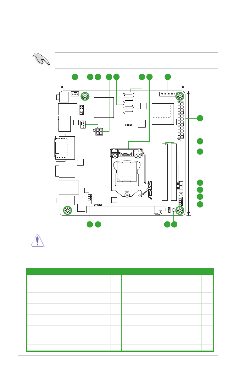
1.2 Motherboard overview
1.2.1 Motherboard layout
Ensure that you install the motherboard into the chassis in the correct orientation. The edge
with external ports goes to the rear part of the chassis.
Place four screws into the holes indicated by circles to secure the motherboard to the
1.2.2 Layout contents
Connectors/Jumpers/Slots/LED Page Connectors/Jumpers/Slots/LED Page
1. CPU and chassis fan connectors (4-pin
CPU_FAN, 4-pin CHA_FAN)
2. USB 2.0 connector (10-1 pin USB56) 1-14 11. DARM LED (DRAM_LED) 1-17
3. ATX power connectors (24-pin EATXPWR,
4-pin ATX12V)
4. Intel® H67 Serial ATA 3.0Gb/s connectors
(7-pin SATA3G_1/2 [blue])
5. Intel® H67 Serial ATA 6.0Gb/s connectors
(7-pin SATA6G_1/2 [gray])
6. Intel® LGA1155 CPU socket 1-3 15. Clear RTC RAM (3-pin CLRTC) 1-7
7. USB 3.0 connector (20-1 pin USB3_34) 1-14 16. Digital audio connector (4-1 pin SPDIF_OUT) 1-11
8. DDR3 SO-DIMM slots 1-3 17. Front panel audio connector (10-1 pin AAFP) 1-15
9. GPU Boost LED (O2LED2) 1-17
ASUS P8H67-I Series 1-2
chassis. DO NOT overtighten the screws! Doing so can damage the motherboard.
1-11 10. GPU Boost switch 1-15
1-10 12. MemOK! switch 1-16
1-12 13. System panel connector (10-1 pin F_PANEL) 1-13
1-12 14. Standby power LED (SB_PWR) 1-17
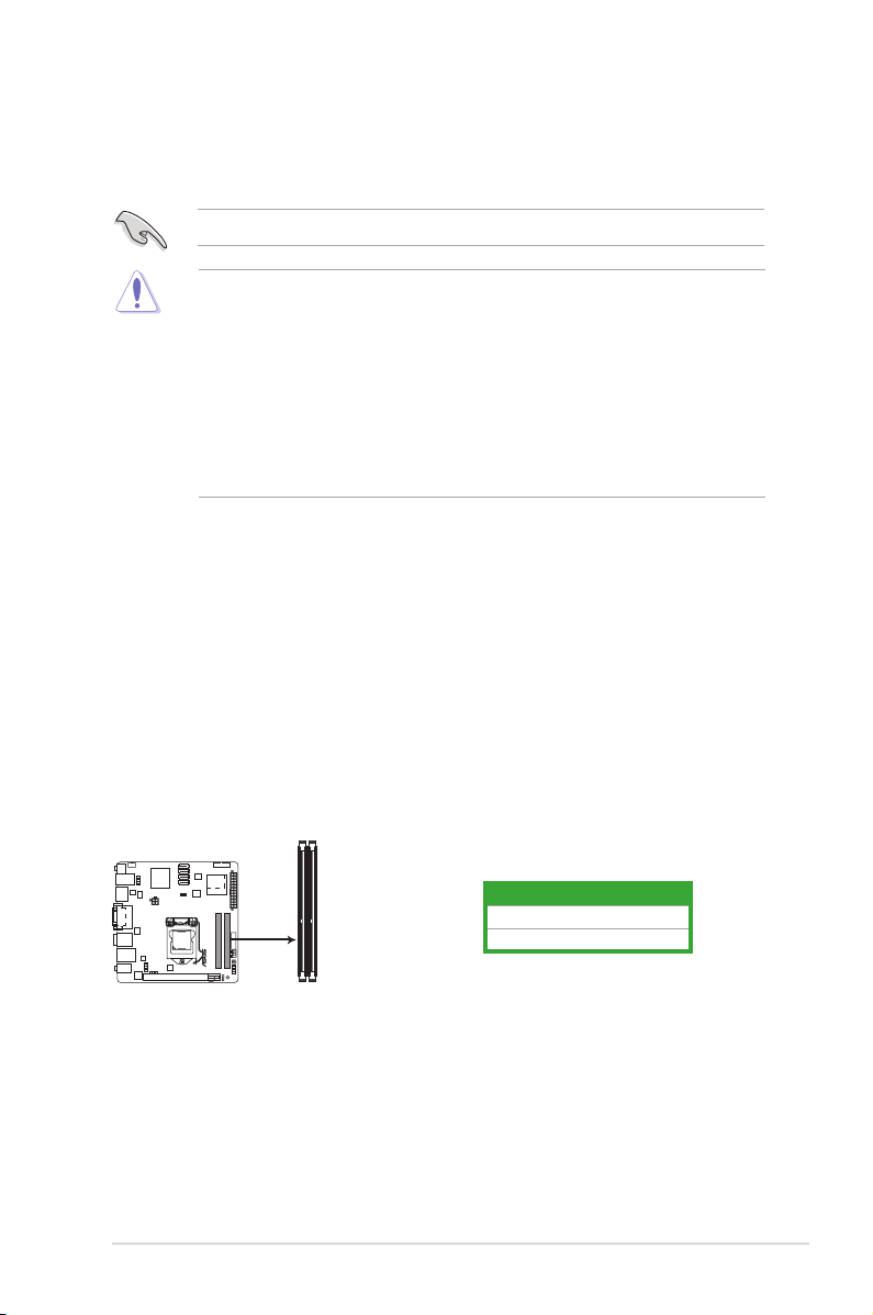
P8H67-I DELUXE
P8H67-I DELUXE 204-pin DDR3 SO-DIMM sockets
DIMM_A1
DIMM_B1
1.3 Central Processing Unit (CPU)
The motherboard comes with a surface mount LGA1155 socket designed for the Intel®
second generation Core™ i7 / Core™ i5 / Core™ i3 processors.
Unplug all power cables before installing the CPU.
• Upon purchase of the motherboard, ensure that the PnP cap is on the socket and the
socket contacts are not bent. Contact your retailer immediately if the PnP cap is missing,
or if you see any damage to the PnP cap/socket contacts/motherboard components.
ASUS will shoulder the cost of repair only if the damage is shipment/transit-related.
• Keep the cap after installing the motherboard. ASUS will process Return Merchandise
Authorization (RMA) requests only if the motherboard comes with the cap on the
LGA1155 socket.
• The product warranty does not cover damage to the socket contacts resulting from
incorrect CPU installation/removal, or misplacement/loss/incorrect removal of the PnP
cap.
1.4 System memory
1.4.1 Overview
The motherboard comes with two Double Data Rate 3 (DDR3) Small Outline Dual Inline
Memory Modules (SO-DIMM) sockets.
A DDR3 module has the same physical dimensions as a DDR2 DIMM but is notched
differently to prevent installation on a DDR2 DIMM socket. DDR3 modules are developed for
better performance with less power consumption.
The gure illustrates the location of the DDR3 DIMM sockets:
1-3 Chapter 1: Product introduction
Channel Sockets
Channel A DIMM_A1
Channel B DIMM_B1
1.4.2 Memory congurations
You may install 512MB, 1GB, 2GB, and 4GB unbuffered non-ECC DDR3 SO-DIMMs into the
DIMM sockets.
• You may install varying memory sizes in Channel A and Channel B. The system maps
the total size of the lower-sized channel for the dual-channel conguration. Any excess
memory from the higher-sized channel is then mapped for single-channel operation.
• According to Intel CPU spec, DIMM voltage below 1.65V is recommended to protect the
CPU.
• Always install DIMMs with the same CAS latency. For optimum compatibility, we
recommend that you obtain memory modules from the same vendor.
• Due to the memory address limitation on 32-bit Windows® OS, when you install 4GB
or more memory on the motherboard, the actual usable memory for the OS can be
about 3GB or less. For effective use of memory, we recommend that you do any of the
following:
- Use a maximum of 3GB system memory if you are using a 32-bit Windows
- Install a 64-bit Windows® OS when you want to install 4GB or more on the
motherboard.
• This motherboard does not support DIMMs made up of 512Mb (64MB) chips or less.
• The default memory operation frequency is dependent on its Serial Presence Detect
(SPD), which is the standard way of accessing information from a memory module.
Under the default state, some memory modules for overclocking may operate at a
lower frequency than the vendor-marked value. To operate at the vendor-marked or at a
higher frequency, refer to section 2.4 Ai Tweaker menu for manual memory frequency
adjustment.
• For system stability, use a more efcient memory cooling system to support a full
memory load (2 SO-DIMMs) or overclocking condition.
®
OS.
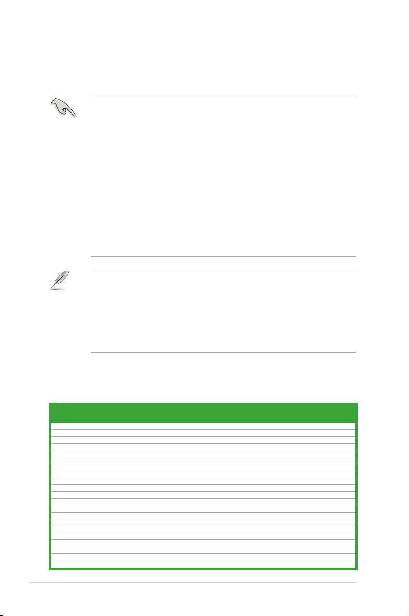
P8H67-I Series Motherboard Qualied Vendors Lists (QVL)
DDR3-1333 MHz capability
Vendors Part No. Size
Transcend JM1333KSU-1G 1GB DS Transcend TK243PDF3 9 - • •
Transcend JM1333KSN-2G 2GB DS Micron 0ND22D9LGK 9 - • •
Transcend JM1333KSU-2G 2GB DS Transcend TK243PDF3 9 - • •
APACER AS01GFA33C9NBGC 1GB DS APACER AM5D5808AEWSBG 9 - • •
CORSAIR CMSO2GX3M1A1333C9 2GB DS CORSAIR 256M8DCJG - - • •
CORSAIR CMSO4GX3M1A1333C9 4GB DS CORSAIR 256M8DCJG - - • •
G.SKILL F3-10666CL9S-2GBSQ 2GB DS G.SKILL D3 256M8GEF 9-9-9-24 - • •
G.SKILL F3-10666CL9S-4GBSQ 4GB DS G.SKILL D3 256M8GEF 9-9-9-24 - • •
GEIL GS31GB1333C9SC 1GB DS GEIL GL1L128M88BA15B 9-9-9-24 1.5V • •
GEIL GS32GB1333C9SC 2GB DS GEIL GL1L128M88BA15KW 9-9-9-24 1.5V • •
GEIL GS34GB1333C9SC 4GB DS GEIL GL1L256M88BA15H 9-9-9-24 1.5V • •
HYNIX HMT125S6TFR8C-H9 2GB DS HYNIX H5TQ1G83TFRH9C - - • •
KINGMAX FSFD45F-B8KL9-NBE 1GB DS KINGMAX KFB8FNLXF-BNF-15A - - • •
KINGMAX FSFE85F-C8KM9-NBE 2GB DS KINGMAX KFC8FNMXF-BXX-15A - - • •
KINGMAX FSFF65F-C8KM9-NAE 4GB DS KINGMAX KFC8FNMXF-BXX-15A - - • •
KINGSTON KVR1333D3S9/1G 1GB DS ELPIDA J1108BDBG-DJ-F 9 1.5V • •
KINGSTON KVR1333D3S9/2G 2GB DS KTC D1288JPNDPLD9U 9 1.5V • •
OCZ OCZ3M13332GK 2GB(2 x 1GB) DS OCZ X43N6416AJ-13 9 - • •
OCZ OCZ3M13334GK 4GB(2 x 2GB) DS - 256X8DDR3 HL 9 - • •
SAMSUNG M471B5773CHS-CH9 2GB DS SAMSUNG K4B2G0846C - - • •
Transcend TS256MSK64V3N 2GB DS MICRON D9LGK - - • •
SS/DSChip
Brand
Chip NO. Timing Voltage
ASUS P8H67-I Series 1-4
DIMM socket support
(Optional)
1 DIMM 2 DIMMs
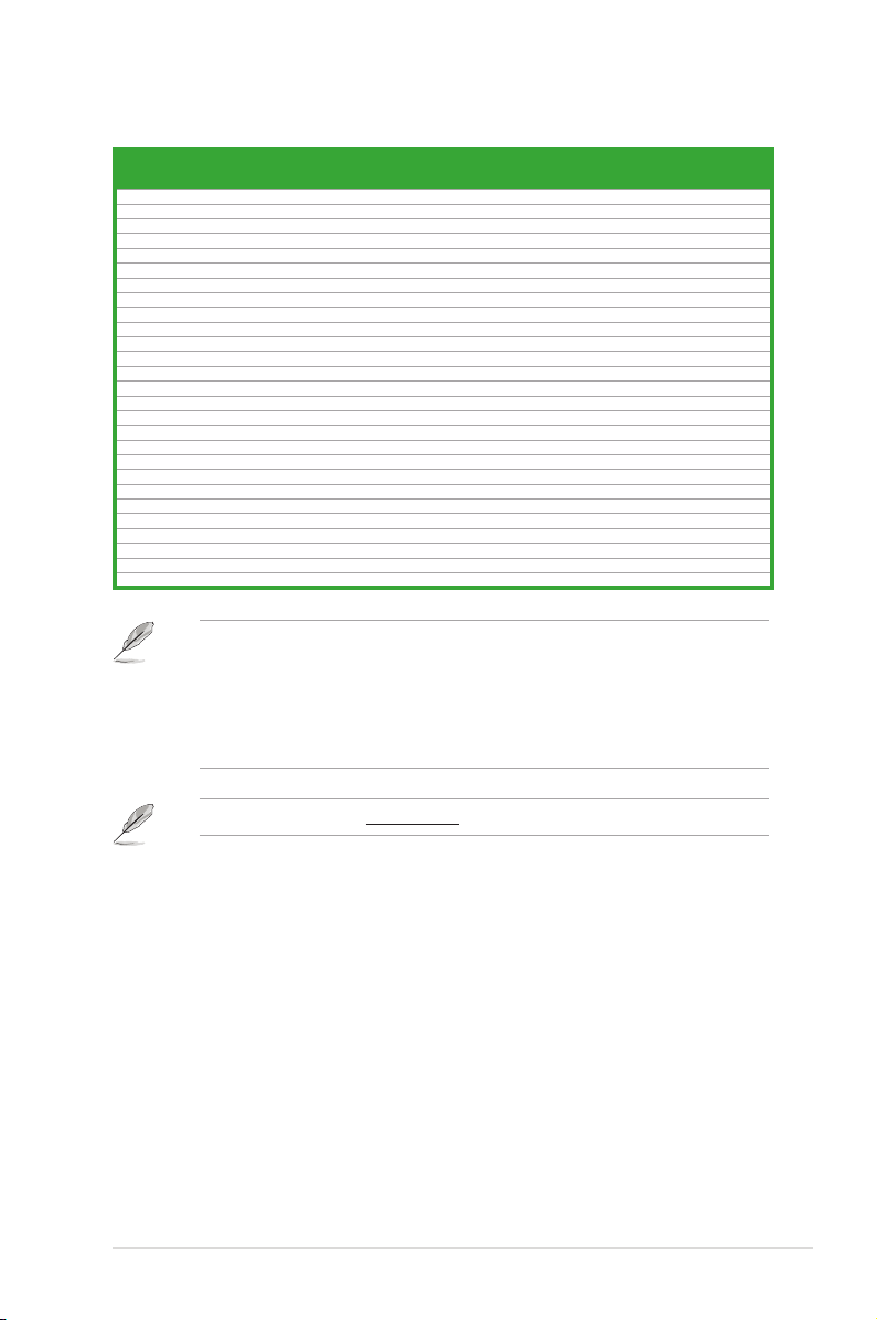
DDR3-1066 MHz capability
Vendors Part No. Size
Transcend JM1066KSU-1G 1GB DS Transcend TK243EDF3 7 - • •
Transcend JM1066KSN-2G 2GB DS HYNIX H5TQ2G83BFRH9C 7 - • •
Transcend JM1066KSU-2G 2GB DS Transcend TK243PDF3 7 - • •
Transcend JM1066KSN-4G 4GB DS Micron 0OD12D9LGK 7 - • •
APACER AS01GFA06C7NBGC 1GB DS APACER AM5D5808DEHSBG 7 - • •
APACER AS02GFA06C7NBGC 2GB DS APACER AM5D5808DQQSBG 7 - • •
CORSAIR CM3X2GSD1066 G 2GB DS CORSAIR 128M8DCJG - - • •
G.SKILL F3-8500CL7S-2GBSQ 2GB DS G.SKILL D3 256M8GEF 7-7-7-20 - • •
G.SKILL F3-8500CL7S-4GBSQ 4GB DS G.SKILL D3 256M8GEF 7-7-7-20 - • •
GEIL GS31GB1066C7SC 1GB DS GEIL GL1L128M88BA15B 7-7-7-20 1.5V • •
GEIL GS32GB1066C7SC 2GB DS GEIL GL1L128M88BA15KW 7-7-7-20 1.5V • •
GEIL GS38GB1066C7DC 8GB(2 x 4GB) DS GEIL GL1L256M88BA15H 7-7-7-20 1.5V • •
HYNIX HMT125S6BFR8C-G7 2GB DS HYNIX H5TQ1G83BFRG7C - - • •
KINGMAX FSED45F-B8KL7-NBF 1GB DS KINGMAX KFB8FNLXF-BNF-15A - - • •
KINGMAX FSEE85F-C8KM7-NBF 2GB DS KINGMAX KFC8FNMXF-BXX-15A - - • •
KINGMAX FSEF65F-C8KM7-NAF 4GB DS KINGMAX KFC8FNMXF-BXX-15A - - • •
KINGSTON KVR1066D3S7/1G 1GB DS KTC D1288JPPDPGD9U 7 1.5V • •
KINGSTON KVR1066D3S7/1G 1GB DS ELPIDA J1108BDSE-DJ-F - 1.5V • •
KINGSTON KVR1066D3S7/2G 2GB DS KTC D1288JPNDPLD9U 7 1.5V • •
SAMSUNG M471B2873EH1-CF8 1GB DS SAMSUNG K4B1G0846E - - • •
SAMSUNG M471B5673FH0-CF8 2GB DS SAMSUNG K4B1G0846F - - • •
Transcend JM1066KSU-1G 1GB DS Transcend TK243PDF3 7 - • •
ADATA DDR3 1066(7) SO-DIMM 1GB DS Hynix H5TQ1G83AFPH9C - - • •
Elixir M2S1G64CBH8A4P-BE 1GB DS Elixir N2CB1616AP-BE - - • •
KINGTIGER 1GB DIMM PC3-8500 1GB DS QIMONDA IDSH1G-04A1F1C-10F - - • •
KINGTIGER 1GB DIMM PC3-8500 1GB DS SAMSUNG K4B1G16460-HCF8 - - • •
KINGTIGER 2GB DIMM PC3-8500 2GB DS HYNIX H5TQ1G83BFRG7C - - • •
SS/DSChip
Brand
Chip NO. Timing Voltage
SS: Single-sided / DS: Double-sided
DIMM support:
• 1 DIMM: Supports one module inserted into any slot as single-channel memory
conguration.
• 2 DIMMs: Supports one pair of modules inserted into both the black slots as one pair of
dual-channel memory conguration.
DIMM socket
support (Optional)
1 DIMM 2 DIMMs
Visit the ASUS website at www.asus.com for the latest QVL.
1-5 Chapter 1: Product introduction
1.5 Expansion slots
In the future, you may need to install expansion cards. The following sub-sections describe
the slots and the expansion cards that they support.
Unplug the power cord before adding or removing expansion cards. Failure to do so may
cause you physical injury and damage motherboard components.
1.5.1 Installing an expansion card
To install an expansion card:
1. Before installing the expansion card, read the documentation that came with it and
make the necessary hardware settings for the card.
2. Remove the system unit cover (if your motherboard is already installed in a chassis).
3. Remove the bracket opposite the slot that you intend to use. Keep the screw for later
use.
4. Align the card connector with the slot and press rmly until the card is completely
seated on the slot.
5. Secure the card to the chassis with the screw you removed earlier.
6. Replace the system cover.
1.5.2 Conguring an expansion card
After installing the expansion card, congure it by adjusting the software settings.
1. Turn on the system and change the necessary BIOS settings, if any. See Chapter 2 for
information on BIOS setup.
2. Assign an IRQ to the card.
3. Install the software drivers for the expansion card.
When using PCI cards on shared slots, ensure that the drivers support “Share IRQ” or that
the cards do not need IRQ assignments. Otherwise, conicts will arise between the two PCI
groups, making the system unstable and the card inoperable.
1.5.3 PCI Express x16 slot
This motherboard has a PCI Express 2.0 x16 slot that supports PCI Express x16 2.0 graphic
cards complying with the PCI Express specications.
1.5.4 Mini PCI Express slot (P8H67-I PRO only)
This motherboard has a Mini PCI Express slot that supports Mini PCI Express cards
complying with the Mini PCI Express specications.
ASUS P8H67-I Series 1-6
1.6 Jumpers
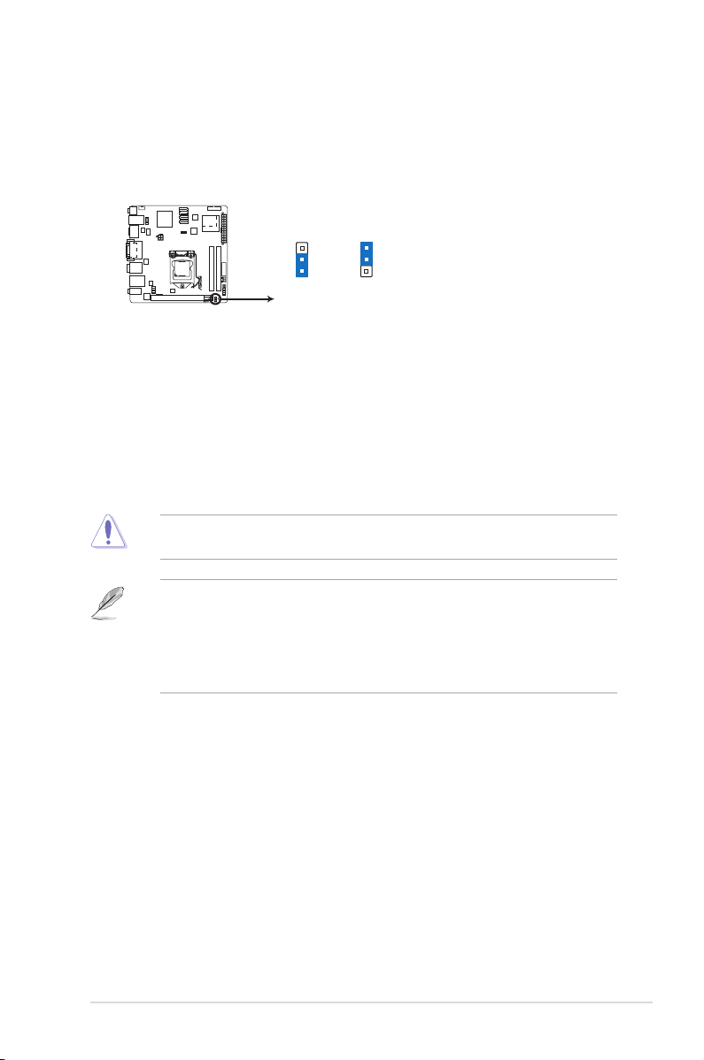
P8H67-I DELUXE
P8H67-I DELUXE Clear RTC RAM
1 2
2 3
Normal
(Default)
Clear RTC
CLRTC
Clear RTC RAM (3-pin CLRTC)
This jumper allows you to clear the Real Time Clock (RTC) RAM in CMOS. You can
clear the CMOS memory of date, time, and system setup parameters by erasing
the CMOS RTC RAM data. The onboard button cell battery powers the RAM data in
CMOS, which include system setup information such as system passwords.
To erase the RTC RAM:
1. Turn OFF the computer and unplug the power cord.
2. Move the jumper cap from pins 1-2 (default) to pins 2-3. Keep the cap on pins 2-3
for about 5-10 seconds, then move the cap back to pins 1-2.
3. Plug the power cord and turn ON the computer.
4. Hold down the <Del> key during the boot process and enter BIOS setup to re-enter
data.
Except when clearing the RTC RAM, never remove the cap on CLRTC jumper default
position. Removing the cap will cause system boot failure!
• If the steps above do not help, remove the onboard battery and move the jumper again
to clear the CMOS RTC RAM data. After clearing the CMOS, reinstall the battery.
• You do not need to clear the RTC when the system hangs due to overclocking. For
system failure due to overclocking, use the CPU Parameter Recall (C.P.R.) feature. Shut
down and reboot the system, then the BIOS automatically resets parameter settings to
default values.
1-7 Chapter 1: Product introduction
 Loading...