

Page 1

P5N32-SLI SE
Deluxe
Motherboard
Page 2

E2708E2708
E2708
E2708E2708
First Edition V1First Edition V1
First Edition V1
First Edition V1First Edition V1
July 2006July 2006
July 2006
July 2006July 2006
Copyright © 2006 ASUSTeK COMPUTER INC. All Rights Reserved.Copyright © 2006 ASUSTeK COMPUTER INC. All Rights Reserved.
Copyright © 2006 ASUSTeK COMPUTER INC. All Rights Reserved.
Copyright © 2006 ASUSTeK COMPUTER INC. All Rights Reserved.Copyright © 2006 ASUSTeK COMPUTER INC. All Rights Reserved.
No part of this manual, including the products and software described in it, may be reproduced,
transmitted, transcribed, stored in a retrieval system, or translated into any language in any form
or by any means, except documentation kept by the purchaser for backup purposes, without the
express written permission of ASUSTeK COMPUTER INC. (“ASUS”).
Product warranty or service will not be extended if: (1) the product is repaired, modified or
altered, unless such repair, modification of alteration is authorized in writing by ASUS; or (2)
the serial number of the product is defaced or missing.
ASUS PROVIDES THIS MANUAL “AS IS” WITHOUT WARRANTY OF ANY KIND, EITHER
EXPRESS OR IMPLIED, INCLUDING BUT NOT LIMITED TO THE IMPLIED WARRANTIES
OR CONDITIONS OF MERCHANTABILITY OR FITNESS FOR A PARTICULAR PURPOSE.
IN NO EVENT SHALL ASUS, ITS DIRECTORS, OFFICERS, EMPLOYEES OR AGENTS BE
LIABLE FOR ANY INDIRECT, SPECIAL, INCIDENTAL, OR CONSEQUENTIAL DAMAGES
(INCLUDING DAMAGES FOR LOSS OF PROFITS, LOSS OF BUSINESS, LOSS OF USE
OR DATA, INTERRUPTION OF BUSINESS AND THE LIKE), EVEN IF ASUS HAS BEEN
ADVISED OF THE POSSIBILITY OF SUCH DAMAGES ARISING FROM ANY DEFECT OR
ERROR IN THIS MANUAL OR PRODUCT.
SPECIFICATIONS AND INFORMATION CONTAINED IN THIS MANUAL ARE FURNISHED
FOR INFORMATIONAL USE ONLY, AND ARE SUBJECT TO CHANGE AT ANY TIME
WITHOUT NOTICE, AND SHOULD NOT BE CONSTRUED AS A COMMITMENT BY ASUS.
ASUS ASSUMES NO RESPONSIBILITY OR LIABILITY FOR ANY ERRORS OR
INACCURACIES THAT MAY APPEAR IN THIS MANUAL, INCLUDING THE PRODUCTS
AND SOFTWARE DESCRIBED IN IT.
Products and corporate names appearing in this manual may or may not be registered
trademarks or copyrights of their respective companies, and are used only for identification or
explanation and to the owners’ benefit, without intent to infringe.
iiii
ii
iiii
Page 3

Contents
Notices ............................................................................................... vii
Safety information ............................................................................ viii
About this guide ................................................................................. ix
P5N32-SLI SE Deluxe specifications summary .................................... xi
Chapter 1: Product introductionChapter 1: Product introduction
Chapter 1: Product introduction
Chapter 1: Product introductionChapter 1: Product introduction
1.1 Welcome! .............................................................................. 1-1
1.2 Package contents ................................................................. 1-1
1.3 Special features .................................................................... 1-2
1.3.1 Product highlights................................................... 1-2
1.3.2 ASUS AI Lifestyle features ..................................... 1-6
1.3.3 Innovative ASUS features ....................................... 1-6
Chapter 2: Hardware informationChapter 2: Hardware information
Chapter 2: Hardware information
Chapter 2: Hardware informationChapter 2: Hardware information
2.1 Before you proceed .............................................................. 2-1
2.2 Motherboard overview .......................................................... 2-2
2.2.1 Placement direction ................................................ 2-2
2.2.2 Screw holes ............................................................ 2-2
2.2.3 ASUS Stack Cool 2 ................................................. 2-3
2.2.4 Motherboard layout ................................................ 2-4
2.2.5 Layout contents ..................................................... 2-5
2.3 Central Processing Unit (CPU) .............................................. 2-7
2.3.1 Installing the CPU.................................................... 2-8
2.3.2 Installing the CPU heatsink and fan ...................... 2-10
2.3.3 Uninstalling the CPU heatsink and fan .................. 2-12
2.3.4 Installing the optional fan ..................................... 2-14
2.4 System memory ................................................................. 2-15
2.4.1 Overview ............................................................... 2-15
2.4.2 Memory configurations ......................................... 2-16
2.4.3 Installing a DIMM ................................................... 2-21
2.4.4 Removing a DIMM ................................................. 2-21
2.5 Expansion slots ................................................................... 2-22
2.5.1 Installing an expansion card .................................. 2-22
2.5.2 Configuring an expansion card.............................. 2-22
2.5.3 Interrupt assignments .......................................... 2-23
iiiiii
iii
iiiiii
Page 4

Contents
2.5.4 PCI slots ................................................................ 2-24
2.5.5 PCI Express x1 slots ............................................. 2-24
2.5.6 PCI Express x4 slot ............................................... 2-24
2.5.7 Two PCI Express x16 slots ................................... 2-25
2.6 Jumper ............................................................................... 2-26
2.7 Connectors ......................................................................... 2-27
2.7.1 Rear panel connectors .......................................... 2-27
2.7.2 Internal connectors............................................... 2-30
Chapter 3: Powering upChapter 3: Powering up
Chapter 3: Powering up
Chapter 3: Powering upChapter 3: Powering up
3.1 Starting up for the first time................................................ 3-1
3.2 Powering off the computer .................................................. 3-2
3.2.1 Using the OS shut down function ........................... 3-2
3.2.2 Using the dual function power switch .................... 3-2
Chapter 4: BIOS setupChapter 4: BIOS setup
Chapter 4: BIOS setup
Chapter 4: BIOS setupChapter 4: BIOS setup
4.1 Managing and updating your BIOS ........................................ 4-1
4.1.1 ASUS Update utility ................................................ 4-1
4.1.2 Creating a bootable floppy disk .............................. 4-4
4.1.3 AFUDOS utility ........................................................ 4-5
4.1.4 ASUS EZ Flash utility .............................................. 4-8
4.2 BIOS setup program ............................................................. 4-9
4.2.1 BIOS menu screen ................................................. 4-10
4.2.2 Menu bar ............................................................... 4-10
4.2.3 Navigation keys .................................................... 4-10
4.2.4 Menu items ........................................................... 4-11
4.2.5 Sub-menu items ................................................... 4-11
4.2.6 Configuration fields .............................................. 4-11
4.2.7 Pop-up window ..................................................... 4-11
4.2.8 Scroll bar .............................................................. 4-11
4.2.9 General help .......................................................... 4-11
iviv
iv
iviv
4.3 Main menu .......................................................................... 4-12
4.3.1 System Time ......................................................... 4-12
4.3.2 System Date ......................................................... 4-12
4.3.3 Legacy Diskette A ................................................ 4-12
Page 5

Contents
4.3.4 Language .............................................................. 4-12
4.3.5 Primary and Secondary IDE Master/Slave ............. 4-13
4.3.6 First, Second, Third, and Fourth SATA Device ..... 4-14
4.3.7 IDE Configuration .................................................. 4-16
4.3.8 System Information ..............................................4-17
4.4 Advanced menu .................................................................. 4-18
4.4.1 JumperFree Configuration .................................... 4-18
4.4.2 USB Configuration................................................. 4-24
4.4.3 LAN2 Cable Status ............................................... 4-25
4.4.4 CPU Configuration ................................................. 4-26
4.4.5 Chipset ................................................................. 4-28
4.4.6 Onboard Devices Configuration ............................4-29
4.4.7 PCI PnP ................................................................. 4-31
4.5 Power menu ........................................................................ 4-32
4.5.1 Suspend Mode ...................................................... 4-32
4.5.2 Repost Video on S3 Resume ................................ 4-32
4.5.3 ACPI 2.0 Support .................................................. 4-33
4.5.4 ACPI APIC Support ................................................ 4-33
4.5.5 APM Configuration ................................................ 4-33
4.5.6 Hardware Monitor ................................................. 4-35
4.6 Boot menu .......................................................................... 4-37
4.6.1 Boot Device Priority .............................................. 4-37
4.6.2 Boot Settings Configuration ................................. 4-38
4.6.3 Security ................................................................ 4-39
4.7 Exit menu ........................................................................... 4-41
Chapter 5: Software supportChapter 5: Software support
Chapter 5: Software support
Chapter 5: Software supportChapter 5: Software support
5.1 Installing an operating system ............................................. 5-1
5.2 Support CD information ........................................................ 5-1
5.2.1 Running the support CD ......................................... 5-1
5.2.2 Drivers menu .......................................................... 5-2
5.2.3 Utilities menu .......................................................... 5-3
5.2.4 Make Disk menu ...................................................... 5-5
5.2.5 Manuals menu ......................................................... 5-6
5.2.6 ASUS Contact information ...................................... 5-7
5.2.7 Other information ................................................... 5-7
vv
v
vv
Page 6

5.3 Software information ......................................................... 5-10
5.3.1 ASUS MyLogo2™ .................................................. 5-10
5.3.2 AI NET 2 ............................................................... 5-12
5.3.3 Audio configurations ............................................ 5-13
®
5.3.4 Using the NVIDIA
Firewall™ ................................. 5-19
5.4 RAID configurations ............................................................ 5-22
5.4.1 Installing hard disks .............................................. 5-23
®
5.4.2 NVIDIA
RAID configurations ................................ 5-24
5.4.3 Silicon Image RAID configurations ........................ 5-31
5.5 Creating a RAID/SATA driver disk ...................................... 5-38
5.5.1 Creating a RAID/SATA driver disk
without entering the OS ....................................... 5-38
®
......
5.5.2 Creating a RAID/SATA driver disk in Windows
®®
®
Chapter 6: NVIDIAChapter 6: NVIDIA
Chapter 6: NVIDIA
Chapter 6: NVIDIAChapter 6: NVIDIA
®®
SLI™ technology support SLI™ technology support
SLI™ technology support
SLI™ technology support SLI™ technology support
5-38
6.1 Overview............................................................................... 6-1
6.2 Dual graphics card setup ...................................................... 6-2
6.2.1 Installing SLI-ready graphics cards ......................... 6-2
6.2.2 Installing the device drivers .................................... 6-5
6.2.3 Enabling the multi-GPU feature in Windows
Appendix: CPU featuresAppendix: CPU features
Appendix: CPU features
Appendix: CPU featuresAppendix: CPU features
..................
6-5
®
A.1 Intel® EM64T ........................................................................ A-1
®
A.2 Enhanced Intel SpeedStep
®
A.3 Intel
Hyper-Threading Technology ...................................... A-3
Technology (EIST) .................... A-1
vivi
vi
vivi
Page 7

Notices
Federal Communications Commission StatementFederal Communications Commission Statement
Federal Communications Commission Statement
Federal Communications Commission StatementFederal Communications Commission Statement
This device complies with Part 15 of the FCC Rules. Operation is subject to
the following two conditions:
•
This device may not cause harmful interference, and
•
This device must accept any interference received including interference
that may cause undesired operation.
This equipment has been tested and found to comply with the limits for a
Class B digital device, pursuant to Part 15 of the FCC Rules. These limits are
designed to provide reasonable protection against harmful interference in a
residential installation. This equipment generates, uses and can radiate radio
frequency energy and, if not installed and used in accordance with
manufacturer’s instructions, may cause harmful interference to radio
communications. However, there is no guarantee that interference will not
occur in a particular installation. If this equipment does cause harmful
interference to radio or television reception, which can be determined by
turning the equipment off and on, the user is encouraged to try to correct
the interference by one or more of the following measures:
•
Reorient or relocate the receiving antenna.
•
Increase the separation between the equipment and receiver.
•
Connect the equipment to an outlet on a circuit different from that to
which the receiver is connected.
•
Consult the dealer or an experienced radio/TV technician for help.
The use of shielded cables for connection of the monitor to the graphics
card is required to assure compliance with FCC regulations. Changes or
modifications to this unit not expressly approved by the party
responsible for compliance could void the user’s authority to operate
this equipment.
Canadian Department of Communications StatementCanadian Department of Communications Statement
Canadian Department of Communications Statement
Canadian Department of Communications StatementCanadian Department of Communications Statement
This digital apparatus does not exceed the Class B limits for radio noise
emissions from digital apparatus set out in the Radio Interference
Regulations of the Canadian Department of Communications.
This class B digital apparatus complies with CanadianThis class B digital apparatus complies with Canadian
This class B digital apparatus complies with Canadian
This class B digital apparatus complies with CanadianThis class B digital apparatus complies with Canadian
ICES-003.ICES-003.
ICES-003.
ICES-003.ICES-003.
viivii
vii
viivii
Page 8

Safety information
Electrical safetyElectrical safety
Electrical safety
Electrical safetyElectrical safety
•
To prevent electrical shock hazard, disconnect the power cable from
the electrical outlet before relocating the system.
•
When adding or removing devices to or from the system, ensure that
the power cables for the devices are unplugged before the signal cables
are connected. If possible, disconnect all power cables from the existing
system before you add a device.
•
Before connecting or removing signal cables from the motherboard,
ensure that all power cables are unplugged.
•
Seek professional assistance before using an adpater or extension cord.
These devices could interrupt the grounding circuit.
•
Make sure that your power supply is set to the correct voltage in your
area. If you are not sure about the voltage of the electrical outlet you
are using, contact your local power company.
•
If the power supply is broken, do not try to fix it by yourself. Contact a
qualified service technician or your retailer.
Operation safetyOperation safety
Operation safety
Operation safetyOperation safety
•
Before installing the motherboard and adding devices on it, carefully read
all the manuals that came with the package.
•
Before using the product, make sure all cables are correctly connected
and the power cables are not damaged. If you detect any damage,
contact your dealer immediately.
•
To avoid short circuits, keep paper clips, screws, and staples away from
connectors, slots, sockets and circuitry.
•
Avoid dust, humidity, and temperature extremes. Do not place the
product in any area where it may become wet.
•
Place the product on a stable surface.
•
If you encounter technical problems with the product, contact a qualified
service technician or your retailer.
viiiviii
viii
viiiviii
Page 9

About this guide
This user guide contains the information you need when installing and
configuring the motherboard.
How this guide is organizedHow this guide is organized
How this guide is organized
How this guide is organizedHow this guide is organized
This guide contains the following parts:
••
Chapter 1: Product introductionChapter 1: Product introduction
•
Chapter 1: Product introduction
••
Chapter 1: Product introductionChapter 1: Product introduction
This chapter describes the features of the motherboard and the new
technology it supports.
••
Chapter 2: Hardware informationChapter 2: Hardware information
•
Chapter 2: Hardware information
••
Chapter 2: Hardware informationChapter 2: Hardware information
This chapter lists the hardware setup procedures that you have to
perform when installing system components. It includes description of
the switches, jumpers, and connectors on the motherboard.
••
Chapter 3: Powering upChapter 3: Powering up
•
Chapter 3: Powering up
••
Chapter 3: Powering upChapter 3: Powering up
This chapter describes the power up sequence and ways of shutting
down the system.
••
Chapter 4: BIOS setupChapter 4: BIOS setup
•
Chapter 4: BIOS setup
••
Chapter 4: BIOS setupChapter 4: BIOS setup
This chapter tells how to change system settings through the BIOS
Setup menus. Detailed descriptions of the BIOS parameters are also
provided.
••
Chapter 5: Software supportChapter 5: Software support
•
Chapter 5: Software support
••
Chapter 5: Software supportChapter 5: Software support
This chapter describes the contents of the support CD that comes
with the motherboard package.
®®
®
®®
••
Chapter 6: NVIDIAChapter 6: NVIDIA
•
Chapter 6: NVIDIA
••
Chapter 6: NVIDIAChapter 6: NVIDIA
This chapter tells how to install SLI-ready PCI Express graphics cards.
••
Appendix: CPU featuresAppendix: CPU features
•
Appendix: CPU features
••
Appendix: CPU featuresAppendix: CPU features
The Appendix describes the CPU features that the motherboard
supports.
Where to find more informationWhere to find more information
Where to find more information
Where to find more informationWhere to find more information
Refer to the following sources for additional information and for product
and software updates.
SLI™ technology support SLI™ technology support
SLI™ technology support
SLI™ technology support SLI™ technology support
1.1.
ASUS websitesASUS websites
1.
ASUS websites
1.1.
ASUS websitesASUS websites
The ASUS website provides updated information on ASUS hardware
and software products. Refer to the ASUS contact information.
2.2.
Optional documentationOptional documentation
2.
Optional documentation
2.2.
Optional documentationOptional documentation
Your product package may include optional documentation, such as
warranty flyers, that may have been added by your dealer. These
documents are not part of the standard package.
ixix
ix
ixix
Page 10

Conventions used in this guideConventions used in this guide
Conventions used in this guide
Conventions used in this guideConventions used in this guide
To make sure that you perform certain tasks properly, take note of the
following symbols used throughout this manual.
DANGER/WARNING: DANGER/WARNING:
DANGER/WARNING: Information to prevent injury to yourself
DANGER/WARNING: DANGER/WARNING:
when trying to complete a task.
CAUTION:CAUTION:
CAUTION: Information to prevent damage to the components
CAUTION:CAUTION:
when trying to complete a task.
IMPORTANT: IMPORTANT:
IMPORTANT: Instructions that you MUST follow to complete a
IMPORTANT: IMPORTANT:
task.
NOTE: NOTE:
NOTE: Tips and additional information to help you complete a
NOTE: NOTE:
task.
TypographyTypography
Typography
TypographyTypography
Bold textBold text
Bold text Indicates a menu or an item to select.
Bold textBold text
Italics
<Key> Keys enclosed in the less-than and greater-than
<Key1+Key2+Key3> If you must press two or more keys
Command Means that you must type the command exactly
Used to emphasize a word or a phrase.
sign means that you must press the enclosed key.
Example: <Enter> means that you must press the
Enter or Return key.
simultaneously, the key names are linked with a
plus sign (+).
Example: <Ctrl+Alt+D>
as shown, then supply the required item or value
enclosed in brackets.
Example: At the DOS prompt, type the command
line:
format A:/S
xx
x
xx
Page 11

P5N32-SLI SE Deluxe specifications summary
CPUCPU
CPU
CPUCPU
LGA775 socket for Intel® Core™2 Extreme/
Intel® Core™2/Intel®Pentium® Processor Extreme
Edition/Intel® Pentium® D/Intel® Pentium® 4/
Intel® Celeron® processors
Compatible with Intel® PCG 05B/05A and 04B/04A
processors
Supports Intel® Enhanced Memory 64 Technology (EM64T)
Supports Enhanced Intel SpeedStep® Technology (EIST)
Supports Intel® Hyper-Threading Technology
ChipsetChipset
Chipset
ChipsetChipset
Front Side BusFront Side Bus
Front Side Bus
Front Side BusFront Side Bus
MemoryMemory
Memory
MemoryMemory
Expansion slotsExpansion slots
Expansion slots
Expansion slotsExpansion slots
Scalable LinkScalable Link
Scalable Link
Scalable LinkScalable Link
Interface (SLI™)Interface (SLI™)
Interface (SLI™)
Interface (SLI™)Interface (SLI™)
NoteNote
N o t e: Visit the ASUS website at www.asus.com for the Intel
NoteNote
Pentium® D CPU and EIST support list.
®
NVIDIA® nForce™ 4 SLI x16
1066/800/533 MHz
Dual-channel memory architecture
4 x 240-pin DIMM sockets support up to 8 GB
unbuffered non-ECC DDR2 667/533 MHz memory
modules
®
Supports the NVIDIA
Dynamic Adaptive Speculative
Preprocessor (DASP) and QuickSync feature
2 x PCI Express™ x16 slots with Scalable Link Interface
(SLI™) support at full x16, x16 mode
1 x PCI Express™ x4 slot
2 x PCI Express™ x1 slots
2 x PCI slots
(PCI 2.2)
SLI™ mode supports:
- 2 x identical SLI™-ready PCI Express™ x16 graphics
cards
NoteNote
N o t e: In SLI mode, the PCI Express x16 slots work at the full
NoteNote
bandwidth of x16 each, for a combined bandwidth of x32.
ASUS SLI Bridge
ASUS PEG Link for dual PCI Express graphics cards
ASUS Two-slot thermal design
AI AudioAI Audio
AI Audio
AI AudioAI Audio
®
Realtek
ALC850 8-channel CODEC
1 x Coaxial S/PDIF out port
1 x Optical S/PDIF out port
Supports Universal Audio Jack (UAJ®) Technology
Supports Audio Sensing and Enumeration Technology
(continued on the next page)
xixi
xi
xixi
Page 12

P5N32-SLI SE Deluxe specifications summary
StorageStorage
Storage
StorageStorage
Dual Gigabit LANDual Gigabit LAN
Dual Gigabit LAN
Dual Gigabit LANDual Gigabit LAN
USBUSB
USB
USBUSB
NVIDIA® nForce™ SLI supports:
- 2 x Ultra DMA 133/100/66/33
- 4 x Serial ATA 3Gb/s devices
- NVRAID for RAID 0, RAID 1, RAID 0+1, RAID 5, and
JBOD configuration
- Up to 8 hard disk drives of Multi-RAID configuration
Silicon Image 3132 SATA controller supports:
- 1 x Internal Serial ATA 3Gb/s hard disk drive
- 1 x External Serial ATA 3Gb/s (SATA On-The-Go)
- RAID 0, RAID 1, and JBOD configuration
AI NET2
Marvell
Marvell® 88E1115 Gigabit LAN PHY
NVIDIA® nForce™ 4 SLI built-in Gigabit MAC with
Supports up to 10 USB 2.0 ports
®
88E8053 Gigabit LAN controller
external Marvell® PHY supports:
- NV ActiveArmor
- NV Firewall
IEEE 1394IEEE 1394
IEEE 1394
IEEE 1394IEEE 1394
ASUS ExclusiveASUS Exclusive
ASUS Exclusive
ASUS ExclusiveASUS Exclusive
OverclockingOverclocking
Overclocking
OverclockingOverclocking
featuresfeatures
features
featuresfeatures
TI 1394a controller supports:
- 2 x IEEE 1394a connectors at midboard
Intelligent overclocking tools:
- AI NOS™ (Non-delay Overclocking System)
- AI Overclocking (intelligent CPU frequency tuner)
- ASUS PEG Link (automatic performance tuning for
single/dual graphics cards)
- ASUS CPU Lock Free*
- ASUS AI Booster Utility
Precision Tweaker supports:
- DIMM voltage: 8-step DRAM voltage control
- Core voltage: Adjustable CPU voltage at 0.0125 V
increment
Stepless Frequency Selection(SFS) allows:
- FSB tuning up to 1600 MHz at 1 MHz
increment, depending on CPU frequency
- Memory tuning from 400 MHz to 1600 MHz
- PCI Express frequency tuning from 100 MHz to
148 MHz at 1 MHz increment
Overclocking protection:
- ASUS C.P.R. (CPU Parameter Recall)
xiixii
xii
xiixii
(continued on the next page)
Page 13

P5N32-SLI SE Deluxe specifications summary
ASUS AI LifestyleASUS AI Lifestyle
ASUS AI Lifestyle
ASUS AI LifestyleASUS AI Lifestyle
featuresfeatures
features
featuresfeatures
Other ASUSOther ASUS
Other ASUS
Other ASUSOther ASUS
special featuresspecial features
special features
special featuresspecial features
BIOS featuresBIOS features
BIOS features
BIOS featuresBIOS features
Rear panelRear panel
Rear panel
Rear panelRear panel
ASUS SATA On-The-Go (External Serial ATA port on the
rear panel
Stack Cool 2 patented fanless cooling technology
Fanless design
AI NET2 network diagnosis before entering the
operating system
ASUS Q-Fan2
ASUS MyLogo2
ASUS EZ Flash
ASUS Multi-language BIOS
8 Mb Flash ROM, AMI BIOS, PnP, DMI2.44, SM BIOS 2.33,
WfM2.0
1 x Parallel port
2 x LAN (RJ-45) ports
4 x USB 2.0 ports
1 x External Serial ATA port
1 x Optical S/PDIF Out port
1 x Coaxial S/PDIF Out port
1 x PS/2 keyboard port (purple)
1 x PS/2 mouse port (green)
8-channel audio ports
InternalInternal
Internal
InternalInternal
connectorsconnectors
connectors
connectorsconnectors
* Only Intel® Pentium® 4 processors (formerly code-named Prescott)
6xx series built on the 90-nm technology support the CPU Lock Free
feature.
1 x Floppy disk drive connector
2 x IDE connectors
4 x NVIDIA
1 x Silicon Image® Serial ATA connector
1 x 24-pin EATX power connector
1 x 8-pin EATX 12 V power connector
2 x USB connectors for 4 additional USB 2.0 ports
1 x Internal audio connectors (CD/AUX)
2 x IEEE 1394a connectors
1 x GAME/MIDI connector
1 x Chassis intrusion connector
1 x Front panel audio connector
CPU (x1), Chassis (x2), Chipset (x2), Power (x1) fan
connectors
System panel connector
®
nForce™ 4 Serial ATA connectors
(continued on the next page)
xiiixiii
xiii
xiiixiii
Page 14

P5N32-SLI SE Deluxe specifications summary
PowerPower
Power
PowerPower
RequirementRequirement
Requirement
RequirementRequirement
Support CDSupport CD
Support CD
Support CDSupport CD
contentscontents
contents
contentscontents
Form FactorForm Factor
Form Factor
Form FactorForm Factor
*Specifications are subject to change without notice.
ATX power supply (with 24-pin and 8-pin 12 V plugs)
ATX 12 V 2.0 compliant
Device drivers
ASUS PC Probe II
ASUS Update
ASUS AI Booster
NVIDIA
®
NV Firewall
NVIDIA® NV RAID
NVIDIA® NV RIS (Remote Installation Service)
Anti-Virus Utility (OEM version)
ATX form factor: 12 in x 9.6 in (30.5 cm x 24.5 cm)
xivxiv
xiv
xivxiv
Page 15

This chapter describes the motherboard
features and the new technologies
it supports.
introduction
Product
1
Page 16

Chapter summary
1
1.1 Welcome! .............................................................................. 1-1
1.2 Package contents ................................................................. 1-1
1.3 Special features .................................................................... 1-2
ASUS P5N32-SLI SE DeluxeASUS P5N32-SLI SE Deluxe
ASUS P5N32-SLI SE Deluxe
ASUS P5N32-SLI SE DeluxeASUS P5N32-SLI SE Deluxe
Page 17

1.1 Welcome!
®®
®
Thank you for buying an ASUSThank you for buying an ASUS
Thank you for buying an ASUS
Thank you for buying an ASUSThank you for buying an ASUS
motherboard!motherboard!
motherboard!
motherboard!motherboard!
®®
P5N P5N
P5N
P5N P5N
33
2-SLI 2-SLI
3
2-SLI
33
2-SLI 2-SLI
SE DeluxeSE Deluxe
SE Deluxe
SE DeluxeSE Deluxe
The motherboard delivers a host of new features and latest technologies,
making it another standout in the long line of ASUS quality motherboards!
Before you start installing the motherboard, and hardware devices on it,
check the items in your package with the list below.
1.2 Package contents
Check your motherboard package for the following items.
MotherboardMotherboard
Motherboard ASUS P5N32-SLI SE Deluxe motherboard
MotherboardMotherboard
I/O modulesI/O modules
I/O modules 1 x IEEE1394a module
I/O modulesI/O modules
1 x Serial port module
1 x 2-port USB 2.0/GAME module
CablesCables
Cables 4 x Serial ATA cables
CablesCables
2 x Serial ATA power cables (dual plugs)
1 x Ultra DMA 133/100/66 cable
1 x IDE cable
1 x Floppy disk drive cable
AccessoriesAccessories
Accessories I/O shield
AccessoriesAccessories
1 x ASUS SLI Bridge
Application CDsApplication CDs
Application CDs ASUS motherboard support CD
Application CDsApplication CDs
DocumentationDocumentation
Documentation User guide
DocumentationDocumentation
If any of the above items is damaged or missing, contact your retailer.
ASUS P5N32-SLI SE DeluxeASUS P5N32-SLI SE Deluxe
ASUS P5N32-SLI SE Deluxe
ASUS P5N32-SLI SE DeluxeASUS P5N32-SLI SE Deluxe
1-11-1
1-1
1-11-1
Page 18
1.3 Special features
1.3.11.3.1
1.3.1
1.3.11.3.1
Latest processor technology Latest processor technology
Latest processor technology
Latest processor technology Latest processor technology
Product highlightsProduct highlights
Product highlights
Product highlightsProduct highlights
The motherboard comes with a 775-pin surface mount Land Grid Array
(LGA) socket designed for the Intel® Pentium® Processor Extreme Edition,
Intel® Pentium® D, Intel® Pentium® 4, and Intel® Celeron® processor in the
775-land package. The motherboard supports Intel
®
processors with 1066/
800/533 MHz Front Side Bus (FSB). The motherboard also supports the
Intel® Hyper-Threading Technology, Intel® Dual-Core Technology and is fully
compatible with Intel® 05B/05A and 04B/04A processors. See page 2-7
for details.
NVIDIANVIDIA
NVIDIA
NVIDIANVIDIA
®®
®
®®
Scalable Link Interface (SLI™) - Intel Scalable Link Interface (SLI™) - Intel
Scalable Link Interface (SLI™) - Intel
Scalable Link Interface (SLI™) - Intel Scalable Link Interface (SLI™) - Intel
®®
®
®®
Edition Edition
Edition
Edition Edition
The NVIDIA® nForce4® Scalable Link Interface (SLI™) - Intel® Edition
technology allows two graphics processing units (GPUs) in a single system.
This technology takes advantage of the PCI Express™ bus architecture and
features intelligent hardware and software solutions that allows multiple
GPUs to work together and achieve exceptional graphics performance. See
Chapter 6 for details.
IntelIntel
Intel
IntelIntel
®
Dual-Core Technology CPU support Dual-Core Technology CPU support
Dual-Core Technology CPU support
Dual-Core Technology CPU support Dual-Core Technology CPU support
The motherboard supports dual-core processors containing two physical
CPU cores with dedicated L2 caches to meet demands for more powerful
processing. See page 2-7 for details.
®®
®
IntelIntel
Intel
IntelIntel
®®
EM64T EM64T
EM64T
EM64T EM64T
The motherboard supports Intel® processors with the Intel® EM64T
(Extended Memory 64 Technology). The Intel
®
EM64T feature allows your
computer to run on 64-bit operating systems and access larger amounts of
system memory for faster and more efficient computing. See the Appendix
for details.
Enhanced Intel SpeedStepEnhanced Intel SpeedStep
Enhanced Intel SpeedStep
Enhanced Intel SpeedStepEnhanced Intel SpeedStep
®
Technology (EIST) Technology (EIST)
Technology (EIST)
Technology (EIST) Technology (EIST)
The Enhanced Intel SpeedStep® Technology (EIST) intelligently manages
the CPU resources by automatically adjusting the CPU voltage and core
frequency depending on the CPU loading and system speed or power
requirement. See the Appendix for details.
1-21-2
1-2
1-21-2
Chapter 1: Product introductionChapter 1: Product introduction
Chapter 1: Product introduction
Chapter 1: Product introductionChapter 1: Product introduction
Page 19
DDR2 memory support DDR2 memory support
DDR2 memory support
DDR2 memory support DDR2 memory support
The motherboard supports DDR2 memory that features data transfer rates of
667 MHz or 533 MHz to meet the higher bandwidth requirements of the
latest 3D graphics, multimedia, and Internet applications. The dual-channel
DDR2 architecture doubles the bandwidth of your system memory to boost
system performance, eliminating bottlenecks with peak bandwidths of up to
10.7 GB/s. See pages 2-15 to 2-20 for details.
®®
®
NVIDIANVIDIA
NVIDIA
NVIDIANVIDIA
®®
QuickSync QuickSync
QuickSync
QuickSync QuickSync
The NVIDIA® nForce4® SLI™ - Intel® Edition memory controller features the
QuickSynch synchronization technology that transfers memory requests
and data between the Front Side Bus (FSB) and memory clock domains in
the shortest amount of time. QuickSync ensures that the memory
controller has the shortest latency between receiving/placing CPU
requests, and between receiving the data from memory and sending it to
the CPU for all FSB and memory speeds.
®®
®
NVIDIANVIDIA
NVIDIA
NVIDIANVIDIA
®®
DASP 3.0 DASP 3.0
DASP 3.0
DASP 3.0 DASP 3.0
The NVIDIA® Dynamic Adaptive Speculative Preprocessor (DASP) 3.0
comes with sophisticated data pre-fetch algorithms in preprocessors that
are tasked to track data threads and pre-fetch appropriate data for
improved performance.
Built-in NVFirewall™ and NVActiveArmor™Built-in NVFirewall™ and NVActiveArmor™
Built-in NVFirewall™ and NVActiveArmor™
Built-in NVFirewall™ and NVActiveArmor™Built-in NVFirewall™ and NVActiveArmor™
The NVIDIA® Firewall™ (NVFirewall™) is an easy-to-use high-performance
desktop firewall application that protects your system from intruders.
Integrated into the NVIDIA® nForce4® SLI™ chipset, it provides advanced
anti-computer-hacking technologies, remote management capabilities, and
a user-friendly setup wizard that improves overall system security.
®
Enhancing your network security is the NVIDIA
ActiveArmor™
(NV ActiveArmor™) engine that provides advanced data packet inspection.
This innovative technology ensures that only safe data packets are passed
on the network. It boosts overall system performance by offloading the
CPU from the rigorous task of filtering data packets. See page 5-19 for
details.
ASUS P5N32-SLI SE DeluxeASUS P5N32-SLI SE Deluxe
ASUS P5N32-SLI SE Deluxe
ASUS P5N32-SLI SE DeluxeASUS P5N32-SLI SE Deluxe
1-31-3
1-3
1-31-3
Page 20

Dual RAID solution Dual RAID solution
Dual RAID solution
Dual RAID solution Dual RAID solution
Onboard RAID controllers provide the motherboard with dual-RAID
functionality that allows you to select the best RAID solution using IDE or
Serial ATA devices.
®
The NVIDIA
nForce4® SLI™ allows RAID 0, RAID 1, RAID 0+1, RAID 5, and
JBOD configuration for four SATA 3 Gb/s and two PATA connectors. See
pages 2-32 and 5-24.
®
The Silicon Image
3132 controller supports two additional Serial ATA
3Gb/s connectors and allows RAID 0, RAID 1, and JBOD configurations
through the internal and external Serial ATA ports. See pages 2-33 and
5-31 for details.
Dual Gigabit LAN solutionDual Gigabit LAN solution
Dual Gigabit LAN solution
Dual Gigabit LAN solutionDual Gigabit LAN solution
The motherboard comes with dual Gigabit LAN controllers to provide the
total solution for your networking needs. These network controllers use the
PCI Express segment to provide faster data bandwidth for your wired or
wireless Internet, LAN, and file sharing requirements. See page 2-28 for
details.
PCI Express™ interface PCI Express™ interface
PCI Express™ interface
PCI Express™ interface PCI Express™ interface
The motherboard fully supports PCI Express, the latest I/O interconnect
technology that speeds up the PCI bus. PCI Express features point-to-point
serial interconnections between devices and allows higher clockspeeds by
carrying data in packets. This high speed interface is software compatible with
existing PCI specifications. See pages 2-24 and 2-25 for details.
CPU Lock FreeCPU Lock Free
CPU Lock Free
CPU Lock FreeCPU Lock Free
This feature allows you to adjust the CPU multiplier to 14x. Setting the
appropriate BIOS setting automatically reduces the CPU multiplier value for
more flexibility when increasing external FSB. See page 4-19 for details.
Only Intel® Pentium® 4 processors (formerly code-named Prescott) 6xx
series built on the 90-nm technology support this feature.
S/PDIF digital sound ready S/PDIF digital sound ready
S/PDIF digital sound ready
S/PDIF digital sound ready S/PDIF digital sound ready
The motherboard supports the S/PDIF technology through the S/PDIF
interfaces on the rear panel and at midboard. The S/PDIF technology turns
your computer into a high-end entertainment system with digital connectivity
to powerful audio and speaker systems. See page 2-29 for details.
1-41-4
1-4
1-41-4
Chapter 1: Product introductionChapter 1: Product introduction
Chapter 1: Product introduction
Chapter 1: Product introductionChapter 1: Product introduction
Page 21

IEEE 1394a support IEEE 1394a support
IEEE 1394a support
IEEE 1394a support IEEE 1394a support
The IEEE 1394a interface provides high-speed and flexible PC connectivity
to a wide range of peripherals and devices compliant to the IEEE 1394a
standard. The IEEE 1394a interface allows up to 400 Mbps transfer rates
through simple, low-cost, high-bandwidth asynchronous (real-time) data
interfacing between computers, peripherals, and consumer electronic
devices such as camcorders, VCRs, printers, TVs, and digital cameras. See
page 2-35 for details.
USB 2.0 technology USB 2.0 technology
USB 2.0 technology
USB 2.0 technology USB 2.0 technology
The motherboard implements the Universal Serial Bus (USB) 2.0
specification, dramatically increasing the connection speed from the
12 Mbps bandwidth on USB 1.1 to a fast 480 Mbps on USB 2.0. USB 2.0 is
backward compatible with USB 1.1. See pages 2-28 and 2-34 for details.
ASUS P5N32-SLI SE DeluxeASUS P5N32-SLI SE Deluxe
ASUS P5N32-SLI SE Deluxe
ASUS P5N32-SLI SE DeluxeASUS P5N32-SLI SE Deluxe
1-51-5
1-5
1-51-5
Page 22

1.3.21.3.2
1.3.2
1.3.21.3.2
Serial ATA II and SATA-On-The-Go Serial ATA II and SATA-On-The-Go
Serial ATA II and SATA-On-The-Go
Serial ATA II and SATA-On-The-Go Serial ATA II and SATA-On-The-Go
The motherboard supports the Serial ATA 3 Gb/s technology through the
Silicon Image Serial ATA interfaces and the NVIDIA® SLI™ - Intel® Edition
chipset. The Serial ATA 3 Gb/s specification provides twice the bandwidth of
the current Serial ATA products with a host of new features, including Native
Command Queuing (NCQ), Power Management (PM) Implementation
Algorithm, and Hot Swap. Serial ATA allows thinner, more flexible cables
with lower pin count and reduced voltage requirements.
Leveraging these Serial ATA 3Gb/s features is the SATA-On-The-Go. This
external port on the rear panel I/O provides smart setup, hot-plug and
support for up to 16 devices with port-multiplier functions. See pages 2-29
and 2-33 for details.
ASUS AI Lifestyle features ASUS AI Lifestyle features
ASUS AI Lifestyle features
ASUS AI Lifestyle features ASUS AI Lifestyle features
ASUS Stack Cool 2 ASUS Stack Cool 2
ASUS Stack Cool 2
ASUS Stack Cool 2 ASUS Stack Cool 2
ASUS Stack Cool 2 is a fan-less and zero-noise cooling solution that lowers
the temperature of critical heat generating components. The motherboard
uses a special design on the printed circuit board (PCB) to dissipate heat
that critical components generate. See page 2-3 for details.
1.3.31.3.3
1.3.3
1.3.31.3.3
AI NOS™ (Non-Delay Overclocking System) AI NOS™ (Non-Delay Overclocking System)
AI NOS™ (Non-Delay Overclocking System)
AI NOS™ (Non-Delay Overclocking System) AI NOS™ (Non-Delay Overclocking System)
ASUS Non-delay Overclocking System™ (NOS) is a technology that
auto-detects the CPU loading and dynamically overclocks the CPU speed
only when needed. See page 4-23 for details.
Precision TweakerPrecision Tweaker
Precision Tweaker
Precision TweakerPrecision Tweaker
This feature allows you to fine tune the CPU/memory voltage and gradually
increase the memory Front Side Bus (FSB) and PCI Express frequency at
1MHz increment to achieve maximum system performance.
Innovative ASUS featuresInnovative ASUS features
Innovative ASUS features
Innovative ASUS featuresInnovative ASUS features
1-61-6
1-6
1-61-6
Chapter 1: Product introductionChapter 1: Product introduction
Chapter 1: Product introduction
Chapter 1: Product introductionChapter 1: Product introduction
Page 23

AI NET 2 AI NET 2
AI NET 2
AI NET 2 AI NET 2
AI NET 2 is a BIOS-based diagnostic tool that detects and reports Ethernet
cable faults and shorts. With this utility, you can easily monitor the
condition of the Ethernet cable(s) connected to the Marvell
port. During the bootup process, AI NET 2 immediately diagnoses the LAN
cable and reports shorts and faults up to 100 meters at 1 meter accuracy.
See pages 4-25 and 5-12 for details.
®
LAN (RJ-45)
AI Audio technology AI Audio technology
AI Audio technology
AI Audio technology AI Audio technology
The motherboard supports 8-channel audio through the onboard Realtek
ALC850 CODEC with 16-bit DAC, a stereo 16-bit ADC, and an AC97 2.3
compatible multi-channel audio designed for PC multimedia systems. It also
provides Jack-Sensing function, S/PDIF out support, interrupt capability and
includes the Realtek® proprietary UAJ® (Universal Audio Jack) technology.
See pages 2-27 and 5-13 for details.
Fanless Design Fanless Design
Fanless Design
Fanless Design Fanless Design
The ASUS fanless design allows multi-directional heat flow from major
thermal sources in the motherboard to lower overall system temperature,
resulting in quieter operation and longer system life.
PEG Link Mode for two graphics cardsPEG Link Mode for two graphics cards
PEG Link Mode for two graphics cards
PEG Link Mode for two graphics cardsPEG Link Mode for two graphics cards
This feature enhances your PCI Express graphics card performance. It allows
the motherboard to automatically adjust the PCI Express graphics link mode
to the correct frequency based on the system configuration. Four
additional settings are available for overclocking the PEG Link Mode. See
page 4-28 for details.
®
ASUS Two-slot thermal designASUS Two-slot thermal design
ASUS Two-slot thermal design
ASUS Two-slot thermal designASUS Two-slot thermal design
The motherboard is designed with one PCI Express x1 slot and one PCI
Express x4 slot placed between the PCI Express x16 slots, allowing
increased airflow between the two PCI Express x16 graphics cards. This
special design permits more room for ventilation, thus lowering the overall
system temperature.
ASUS P5N32-SLI SE DeluxeASUS P5N32-SLI SE Deluxe
ASUS P5N32-SLI SE Deluxe
ASUS P5N32-SLI SE DeluxeASUS P5N32-SLI SE Deluxe
1-71-7
1-7
1-71-7
Page 24

ASUS Q-Fan 2 technology ASUS Q-Fan 2 technology
ASUS Q-Fan 2 technology
ASUS Q-Fan 2 technology ASUS Q-Fan 2 technology
The ASUS Q-Fan 2 technology smartly adjusts the CPU and chassis fan 1
speeds according to the system loading to ensure quiet, cool, and efficient
operation. See page 4-35 for details.
ASUS Multi-language BIOS ASUS Multi-language BIOS
ASUS Multi-language BIOS
ASUS Multi-language BIOS ASUS Multi-language BIOS
The multi-language BIOS allows you to select the language of your choice
from the available options. The localized BIOS menus allow easier and faster
configuration. See page 4-12 for details.
ASUS MyLogo2™ ASUS MyLogo2™
ASUS MyLogo2™
ASUS MyLogo2™ ASUS MyLogo2™
This new feature present in the motherboard allows you to personalize and
add style to your system with customizable boot logos. See page 5-10 for
details.
C.P.R. (CPU Parameter Recall) C.P.R. (CPU Parameter Recall)
C.P.R. (CPU Parameter Recall)
C.P.R. (CPU Parameter Recall) C.P.R. (CPU Parameter Recall)
The C.P.R. feature of the motherboard BIOS allows automatic re-setting to
the BIOS default settings in case the system hangs due to overclocking.
When the system hangs due to overclocking, C.P.R. eliminates the need to
open the system chassis and clear the RTC data. Simply shut down and
reboot the system, and the BIOS automatically restores the CPU default
setting for each parameter.
1-81-8
1-8
1-81-8
Chapter 1: Product introductionChapter 1: Product introduction
Chapter 1: Product introduction
Chapter 1: Product introductionChapter 1: Product introduction
Page 25

This chapter lists the hardware setup
procedures that you have to perform
when installing system components.
It includes description of the jumpers
and connectors on the motherboard.
information
Hardware
2
Page 26

Chapter summary
2
2.1 Before you proceed .............................................................. 2-1
2.2 Motherboard overview .......................................................... 2-2
2.3 Central Processing Unit (CPU) .............................................. 2-7
2.4 System memory ................................................................. 2-15
2.5 Expansion slots ................................................................... 2-22
2.6 Jumper ............................................................................... 2-26
2.7 Connectors ......................................................................... 2-27
ASUS P5N32-SLI SE DeluxeASUS P5N32-SLI SE Deluxe
ASUS P5N32-SLI SE Deluxe
ASUS P5N32-SLI SE DeluxeASUS P5N32-SLI SE Deluxe
Page 27
2.1 Before you proceed
®
d
Take note of the following precautions before you install motherboard
components or change any motherboard settings.
• Unplug the power cord from the wall socket before touching any
component.
• Use a grounded wrist strap or touch a safely grounded object or to
a metal object, such as the power supply case, before handling
components to avoid damaging them due to static electricity.
• Hold components by the edges to avoid touching the ICs on them.
• Whenever you uninstall any component, place it on a grounded
antistatic pad or in the bag that came with the component.
Before you install or remove any component, ensureBefore you install or remove any component, ensure
•
Before you install or remove any component, ensure
Before you install or remove any component, ensureBefore you install or remove any component, ensure
that the ATX power supply is switched off or thethat the ATX power supply is switched off or the
that the ATX power supply is switched off or the
that the ATX power supply is switched off or thethat the ATX power supply is switched off or the
power cord is detached from the power supply. power cord is detached from the power supply.
power cord is detached from the power supply. Failure
power cord is detached from the power supply. power cord is detached from the power supply.
to do so may cause severe damage to the motherboard, peripherals,
and/or components.
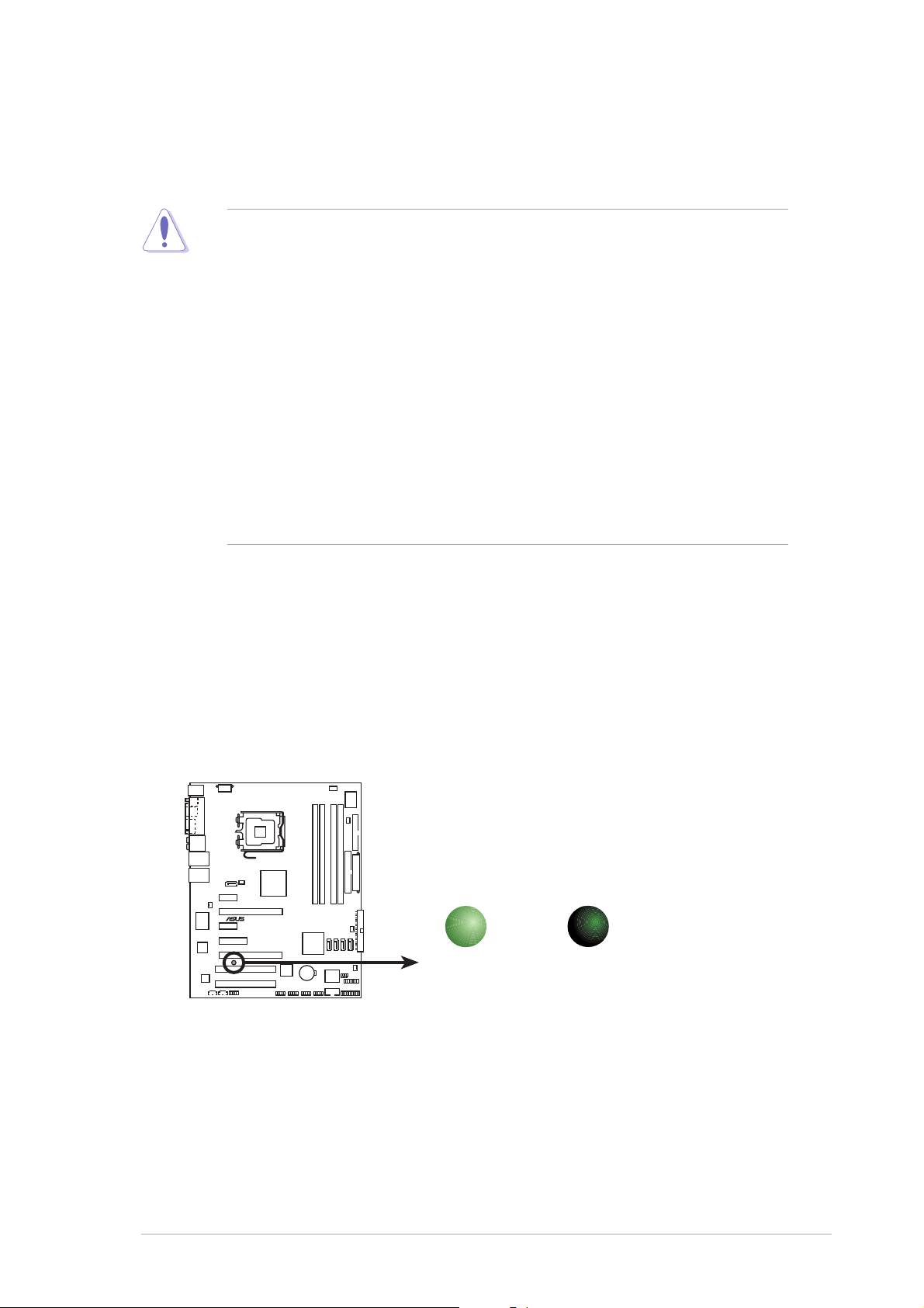
Onboard LEDOnboard LED
Onboard LED
Onboard LEDOnboard LED
The motherboard comes with a standby power LED. The green LED
lights up to indicate that the system is ON, in sleep mode, or in
soft-off mode. This is a reminder that you should shut down the
system and unplug the power cable before removing or plugging in
any motherboard component. The illustration below shows the
location of the onboard LED.
P5N32-SLI SE Deluxe
P5N32-SLI SE Deluxe Onboard LED
ON
Standby
Power
SB_PWR
OFF
Powere
Off
ASUS P5N32-SLI SE DeluxeASUS P5N32-SLI SE Deluxe
ASUS P5N32-SLI SE Deluxe
ASUS P5N32-SLI SE DeluxeASUS P5N32-SLI SE Deluxe
2-12-1
2-1
2-12-1
Page 28
®
2.2 Motherboard overview
Before you install the motherboard, study the configuration of your chassis
to ensure that the motherboard fits into it.
Make sure to unplug the power cord before installing or removing the
motherboard. Failure to do so can cause you physical injury and damage
motherboard components.
2.2.12.2.1
2.2.1
2.2.12.2.1
Placement directionPlacement direction
Placement direction
Placement directionPlacement direction
When installing the motherboard, make sure that you place it into the
chassis in the correct orientation. The edge with external ports goes to the
rear part of the chassis as indicated in the image below.
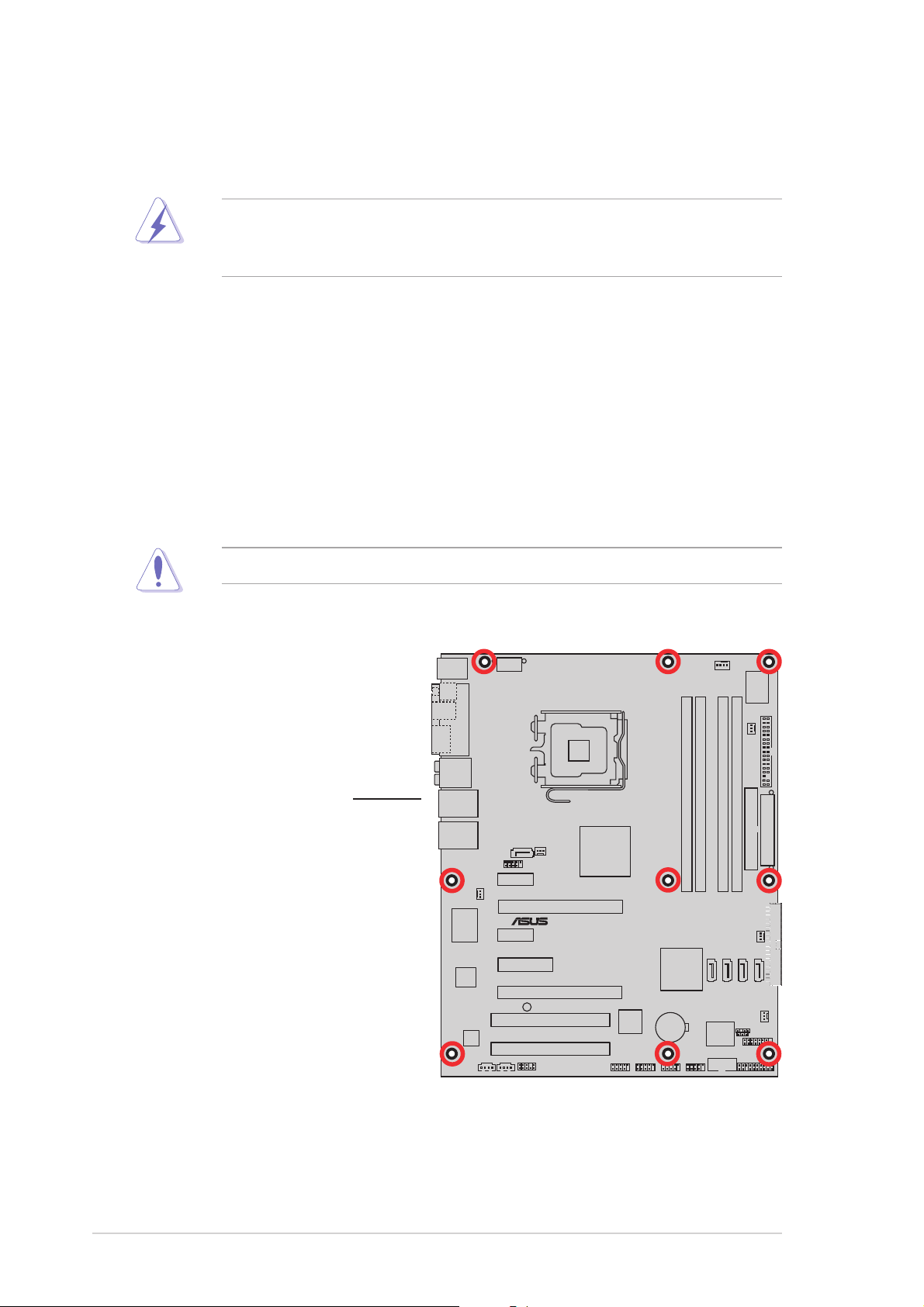
2.2.22.2.2
2.2.2
2.2.22.2.2
Screw holesScrew holes
Screw holes
Screw holesScrew holes
Place nine (9) screws into the holes indicated by circles to secure the
motherboard to the chassis.
Do not overtighten the screws! Doing so can damage the motherboard.
Place this side towardsPlace this side towards
Place this side towards
Place this side towardsPlace this side towards
the rear of the chassisthe rear of the chassis
the rear of the chassis
the rear of the chassisthe rear of the chassis
P5N32-SLI SE Deluxe
2-22-2
2-2
2-22-2
Chapter 2: Hardware informationChapter 2: Hardware information
Chapter 2: Hardware information
Chapter 2: Hardware informationChapter 2: Hardware information
Page 29
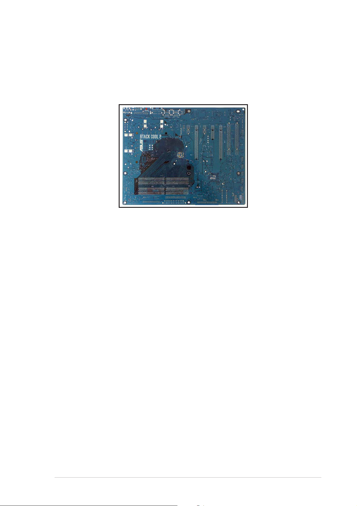
2.2.32.2.3
2.2.3
2.2.32.2.3
The motherboard comes with the ASUS Stack Cool 2 cooling solution that
lowers the temperature of critical heat generating components. The
motherboard uses a special design on the printed circuit board (PCB) to
dissipate heat that critical components generate.
ASUS Stack Cool 2ASUS Stack Cool 2
ASUS Stack Cool 2
ASUS Stack Cool 2ASUS Stack Cool 2
ASUS P5N32-SLI SE DeluxeASUS P5N32-SLI SE Deluxe
ASUS P5N32-SLI SE Deluxe
ASUS P5N32-SLI SE DeluxeASUS P5N32-SLI SE Deluxe
2-32-3
2-3
2-32-3
Page 30
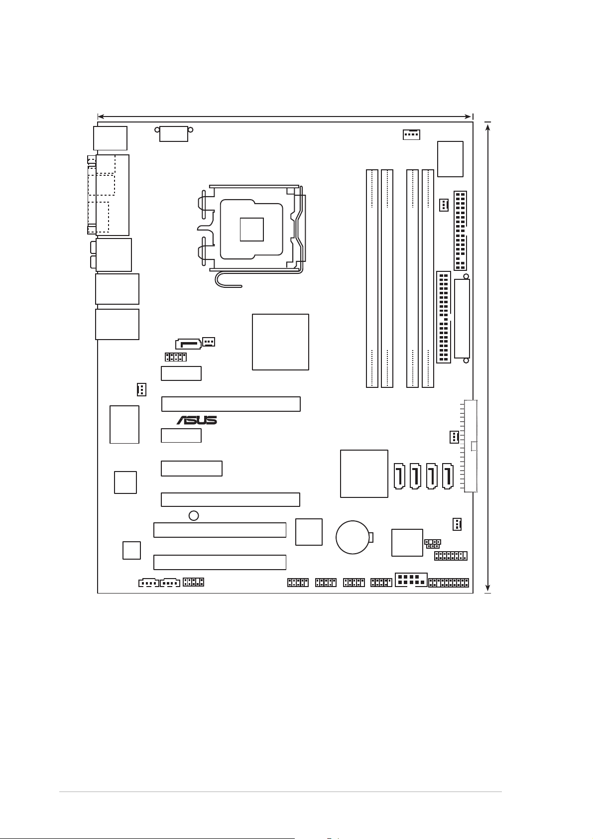
2.2.42.2.4
®
24.5cm (9.6in)
2.2.4
2.2.42.2.4
PS/2KBMS
T: Mouse
B: Keyboard
SPDIF_O
SPDIF_O2
PARALLEL PORT
ESATA
AUDIO
LAN2_USB34
Motherboard layoutMotherboard layout
Motherboard layout
Motherboard layoutMotherboard layout
EATX12V
LGA775
CPU_FAN
Super
PWR_FAN
I/O
FLOPPY
LAN1_USB12
CHA_FAN1
Marvell
Marvell
88E8053
ACL850
PHY
SATA_RAID1
PCIEX1_1
PCIEX1_2
AUX
CD
USB910
PCIEX4_1
SB_PWR
NB_FAN
PCIEX16_1
PCIEX16_2
PCI1
PCI2
FP_AUDIO
®
nVidia
nForce™4 SLI
®
Edition
Intel
IE1394_2
TSB43AB22A
IE1394_1
DDR2 DIMM_A1 (64 bit,240-pin module)
DDR2 DIMM_A2 (64 bit,240-pin module)
P5N32-SLI SE Deluxe
SATA1 SATA2 SATA3 SATA4
®
nVidia
nForce™4 SLI
CR2032 3V
Lithium Cell
CMOS Power
8Mb
BIOS
COM1
USB78USB56
EATXPWR
DDR2 DIMM_B2 (64 bit,240-pin module)
DDR2 DIMM_B1 (64 bit,240-pin module)
SEC_IDE
CHA_FAN2
SB_FAN
CHASSIS
CLRTC
GAME
PANEL
30.5cm (12.0in)
PRI_IDE
2-42-4
2-4
2-42-4
Chapter 2: Hardware informationChapter 2: Hardware information
Chapter 2: Hardware information
Chapter 2: Hardware informationChapter 2: Hardware information
Page 31

2.2.52.2.5
2.2.5
2.2.52.2.5
Layout contentsLayout contents
Layout contents
Layout contentsLayout contents
SlotsSlots
Slots
SlotsSlots
PagePage
Page
PagePage
1. DDR2 DIMM slots 2-15
2. PCI slots 2-24
3. PCI Express x1 slots 2-24
4. PCI Express x 4 slot 2-24
5. PCI Express x16 slots 2-25
JumperJumper
Jumper
JumperJumper
PagePage
Page
PagePage
1. Clear RTC RAM (3-pin CLRTC) 2-26
Rear panel connectorsRear panel connectors
Rear panel connectors
Rear panel connectorsRear panel connectors
PagePage
Page
PagePage
1. PS/2 mouse port (green) 2-27
2. Parallel port 2-27
3. Side Speaker Out port (black) 2-27
4. Rear Speaker Out port (gray) 2-27
5. Line In port (light blue) 2-27
6. Line Out port (lime) 2-27
7. LAN 2 (RJ-45) 2-28
8. LAN 1 (RJ-45) 2-28
9. USB 2.0 ports 1 and 2 2-28
10. USB 2.0 ports 3 and 4 2-28
11. Microphone port (pink) 2-28
12. Center/Subwoofer port (orange) 2-28
13. External SATA port 2-29
14. Optical S/PDIF Out port 2-29
15. Coaxial S/PDIF Out port 2-29
16. PS/2 keyboard port (purple) 2-29
ASUS P5N32-SLI SE DeluxeASUS P5N32-SLI SE Deluxe
ASUS P5N32-SLI SE Deluxe
ASUS P5N32-SLI SE DeluxeASUS P5N32-SLI SE Deluxe
2-52-5
2-5
2-52-5
Page 32

Internal connectorsInternal connectors
Internal connectors
Internal connectorsInternal connectors
PagePage
Page
PagePage
1. Floppy disk drive connector (34-1 pin FLOPPY) 2-30
2. Primary IDE connector (40-1 pin PRI_IDE) 2-31
3. Secondary IDE connector (40-1 pin SEC_IDE) 2-31
®
4. NVIDIA
SATA connectors
(7-pin SATA1 [blue], SATA2 [blue], SATA3 [blue], SATA4 [blue]) 2-32
5. Silicon Image® SATA RAID connector (7-pin SATA_RAID1 [red]) 2-33
6. Optical drive audio connector (4-pin CD) 2-34
7. Auxiliary audio connector (4-pin AUX) 2-34
8. USB connectors (10-1 pin USB56, USB78, USB910) 2-34
9. Front panel audio connector (10-1 pin FP_AUDIO) 2-35
10. IEEE 1394 port connectors (10-1 pin IE1394_1, IE1394_2) 2-35
11. GAME/MIDI port connector (16-1 pin GAME) 2-36
12. Serial port connector (10-1 pin COM1) 2-36
13. CPU, Chassis, Northbridge, and Power Fan connectors
(4-pin CPU_FAN, 3-pin PWR_FAN, 3-pin NB_FAN,
3-pin SB_FAN, 3-pin CHA_FAN1, 3-pin CHA_FAN2) 2-37
14. Chassis intrusion connector (4-1 pin CHASSIS) 2-38
15. ATX power connectors
(24-pin EATXPWR, 8-pin EATX12V) 2-38
16. System panel connector (20-pin PANEL) 2-40
•
System power LED (Green 3-pin PLED)
•
Hard disk drive activity LED (Red 2-pin IDE_LED)
•
System warning speaker (Orange 4-pin SPEAKER)
•
ATX power button/soft-off button (Yellow 2-pin PWR)
•
Reset button (Blue 2-pin RESET)
2-62-6
2-6
2-62-6
Chapter 2: Hardware informationChapter 2: Hardware information
Chapter 2: Hardware information
Chapter 2: Hardware informationChapter 2: Hardware information
Page 33

2.3 Central Processing Unit (CPU)
The motherboard comes with a surface mount LGA775 socket designed for
the Intel® Pentium® D, Intel® Pentium® 4 and Intel® Celeron® processors in
the 775-land package.
®
This motherboard supports the Intel
the latest CPU with embedded dual physical cores and Hyper-Threading
technology, making four CPU threads possible. Refer to the table below for
the operating system support status.
OS licensing support listOS licensing support list
OS licensing support list
OS licensing support listOS licensing support list
Intel Dual-Core CPU supportIntel Dual-Core CPU support
Intel Dual-Core CPU support
Intel Dual-Core CPU supportIntel Dual-Core CPU support
Windows® 2000 Professional
Windows® 2000 Advanced Server Windows® 2000 Advanced Server
Windows® XP Home Windows® XP Home
Windows® XP Professional Windows® XP Professional
®
Windows
Enterprise Enterprise
Server 2003 - Standard, Windows® Server 2003 - Standard,
Pentium® Processor Extreme Edition,
Intel Intel
Dual-Core CPU andDual-Core CPU and
Intel
Dual-Core CPU and
Intel Intel
Dual-Core CPU andDual-Core CPU and
HyperHyper
Hyper
HyperHyper
sup sup
sup
sup sup
--
Threading TechnologyThreading Technology
-
Threading Technology
--
Threading TechnologyThreading Technology
portport
port
portport
•
Install a chassis fan with at least a speed of 2400 rpm and 8 CFM
turnrate when using a dual-core CPU to ensure system stability.
Overheating can permanently damage the system and/or CPU.
• Install an additional chassis fan to ensure better air flow when
overclocking.
• Upon purchase of the motherboard, make sure that the PnP cap is
on the socket and the socket contacts are not bent. Contact your
retailer immediately if the PnP cap is missing, or if you see any
damage to the PnP cap/socket contacts/motherboard components.
ASUS will shoulder the cost of repair only if the damage is shipment/
transit-related.
•
Keep the cap after installing the motherboard. ASUS will process
Return Merchandise Authorization (RMA) requests only if the
motherboard comes with the cap on the LGA775 socket.
• The product warranty does not cover damage to the socket
contacts resulting from incorrect CPU installation/removal, or
misplacement/loss/incorrect removal of the PnP cap.
ASUS P5N32-SLI SE DeluxeASUS P5N32-SLI SE Deluxe
ASUS P5N32-SLI SE Deluxe
ASUS P5N32-SLI SE DeluxeASUS P5N32-SLI SE Deluxe
2-72-7
2-7
2-72-7
Page 34

2.3.12.3.1
®
2.3.1
2.3.12.3.1
Installing the CPUInstalling the CPU
Installing the CPU
Installing the CPUInstalling the CPU
To install a CPU:
1. Locate the CPU socket on the motherboard.
P5N32-SLI SE Deluxe
P5N32-SLI SE Deluxe CPU Socket 775
Before installing the CPU, make sure that the socket box is facing
towards you and the load lever is on your left.
2. Press the load lever with your thumb (A), then move it to the left (B)
until it is released from the retention tab.
Retention tabRetention tab
Retention tab
Retention tabRetention tab
A
PnP capPnP cap
PnP cap
Load leverLoad lever
Load lever
Load leverLoad lever
B
This side of theThis side of the
This side of the
This side of theThis side of the
socket box shouldsocket box should
socket box should
socket box shouldsocket box should
face you.face you.
face you.
face you.face you.
PnP capPnP cap
To prevent damage to the socket pins, do not remove the PnP cap
unless you are installing a CPU.
3. Lift the load lever in the direction
of the arrow to a 135º angle.
2-82-8
2-8
2-82-8
Chapter 2: Hardware informationChapter 2: Hardware information
Chapter 2: Hardware information
Chapter 2: Hardware informationChapter 2: Hardware information
Page 35

4. Lift the load plate with your
thumb and forefinger to a 100º
angle (A), then push the PnP cap
from the load plate window to
remove (B).
5. Position the CPU over
the socket, making sure
that the gold triangle is
on the bottom-left
corner of the socket.
The socket alignment
Alignment keyAlignment key
Alignment key
Alignment keyAlignment key
key should fit into the
CPU notch.
Gold triangle markGold triangle mark
Gold triangle mark
Gold triangle markGold triangle mark
Load plateLoad plate
Load plate
Load plateLoad plate
B
A
The CPU fits in only one correct orientation. DO NOT force the CPU into
the socket to prevent bending the connectors on the socket and
damaging the CPU!
6. Close the load plate (A), then
push the load lever (B) until
it snaps into the retention
tab.
The motherboard supports Intel® Pentium® 4 LGA775 processors with
the Intel® Enhanced Memory 64 Technology (EM64T), Enhanced Intel
SpeedStep® Technology (EIST), and Hyper-Threading Technology. Refer
to the Appendix for more information on these CPU features.
A
B
ASUS P5N32-SLI SE DeluxeASUS P5N32-SLI SE Deluxe
ASUS P5N32-SLI SE Deluxe
ASUS P5N32-SLI SE DeluxeASUS P5N32-SLI SE Deluxe
2-92-9
2-9
2-92-9
Page 36

2.3.22.3.2
2.3.2
2.3.22.3.2
Installing the CPU heatsink and fanInstalling the CPU heatsink and fan
Installing the CPU heatsink and fan
Installing the CPU heatsink and fanInstalling the CPU heatsink and fan
Intel® LGA775 processors require a specially designed heatsink and fan
assembly to ensure optimum thermal condition and performance.
•
When you buy a boxed Intel® processor, the package includes the
CPU fan and heatsink assembly. If you buy a CPU separately, make
sure that you use only Intel®-certified multi-directional heatsink and
fan.
•
Your Intel® LGA775 processor heatsink and fan assembly comes in a
push-pin design and requires no tool to install.
•
If you purchased a separate CPU heatsink and fan assembly, make
sure that you have properly applied Thermal Interface Material to the
CPU heatsink or CPU before you install the heatsink and fan
assembly.
Make sure that you have installed the motherboard to the chassis before
you install the CPU fan and heatsink assembly.
To install the CPU heatsink and fan:
1. Place the heatsink on top of
the installed CPU, making sure
that the four fasteners match
the holes on the motherboard.
Orient the heatsink and fan
assembly such that the CPU
fan cable is closest to the
CPU fan connector.
Narrow endNarrow end
Narrow end
Narrow endNarrow end
of the grooveof the groove
of the groove
of the grooveof the groove
Motherboard holeMotherboard hole
Motherboard hole
Motherboard holeMotherboard hole
FastenerFastener
Fastener
FastenerFastener
2-102-10
2-10
2-102-10
Make sure to orient each fastener with the narrow end of the groove
pointing outward. (The photo shows the groove shaded for emphasis.)
Chapter 2: Hardware informationChapter 2: Hardware information
Chapter 2: Hardware information
Chapter 2: Hardware informationChapter 2: Hardware information
Page 37

2. Push down two fasteners at a
®
r
time in a diagonal sequence to
secure the heatsink and fan
assembly in place.
B
A
A
A
B
B
A
B
3. Connect the CPU fan cable to the connector on the motherboard
labeled CPU_FAN.
CPU_FAN
GND
P5N32-SLI SE Deluxe
CPU FAN IN
CPU FAN PWR
CPU FAN PWM
P5N32-SLI SE Deluxe CPU fan connecto
• Do not forget to connect the CPU fan connector! Hardware
monitoring errors can occur if you fail to plug this connector.
• The retention module of some third-party CPU heatsink and fan can
interfere with chipset components at the bottom of the board.
Before purchasing a separate CPU heatsink and fan, make sure that
it will not interfere with the chipset components.
2-112-11
2-11
ASUS P5N32-SLI SE DeluxeASUS P5N32-SLI SE Deluxe
ASUS P5N32-SLI SE Deluxe
ASUS P5N32-SLI SE DeluxeASUS P5N32-SLI SE Deluxe
2-112-11
Page 38

2.3.32.3.3
2.3.3
2.3.32.3.3
Uninstalling the CPU heatsink and fanUninstalling the CPU heatsink and fan
Uninstalling the CPU heatsink and fan
Uninstalling the CPU heatsink and fanUninstalling the CPU heatsink and fan
To uninstall the CPU heatsink and fan:
1. Disconnect the CPU fan cable
from the connector on the
motherboard.
2. Rotate each fastener
counterclockwise.
3. Pull up two fasteners at a time
in a diagonal sequence to
disengage the heatsink and fan
assembly from the
motherboard.
B
A
A
A
B
B
A
4. Carefully remove the heatsink
and fan assembly from the
motherboard.
B
2-122-12
2-12
2-122-12
Chapter 2: Hardware informationChapter 2: Hardware information
Chapter 2: Hardware information
Chapter 2: Hardware informationChapter 2: Hardware information
Page 39

5. Rotate each fastener clockwise
to ensure correct orientation
when reinstalling.
The narrow end of the
groove should point outward
after resetting. (The photo
shows the groove shaded for
emphasis.)
Narrow end of the grooveNarrow end of the groove
Narrow end of the groove
Narrow end of the grooveNarrow end of the groove
Refer to the documentation in the boxed or stand-alone CPU fan
package for detailed information on CPU fan installation.
ASUS P5N32-SLI SE DeluxeASUS P5N32-SLI SE Deluxe
ASUS P5N32-SLI SE Deluxe
ASUS P5N32-SLI SE DeluxeASUS P5N32-SLI SE Deluxe
2-132-13
2-13
2-132-13
Page 40

2.3.42.3.4
2.3.4
2.3.42.3.4
Installing the optional fanInstalling the optional fan
Installing the optional fan
Installing the optional fanInstalling the optional fan
Install the optional fan
cooler. Installing the optional fan with an active CPU cooler will interfere
with the airflow and destabilize the system.
only only
only if you are using a passive cooler or a water
only only
1. Position the fan above the pipe
and heatsink assembly.
2. Fit the grooved edge to the
heatsink.
3. Carefully push down the fan
until it snugly fits the heatsink,
then connect the fan cables.
•
Plug the optional fan cables to the NB_FAN and/or PWR_FAN
connector on the motherboard.
•
Make sure the optional fan is installed correctly to prevent damage
to the fan and motherboard components.
Do not tilt the fan.
4. The above photo shows the
fans installed on the
motherboard.
Do not install the fan with its rear
side facing you.
2-142-14
2-14
2-142-14
Chapter 2: Hardware informationChapter 2: Hardware information
Chapter 2: Hardware information
Chapter 2: Hardware informationChapter 2: Hardware information
Page 41

2.4 System memory
®
s
2.4.12.4.1
2.4.1
2.4.12.4.1
OverviewOverview
Overview
OverviewOverview
The motherboard comes with four Double Data Rate 2 (DDR2) Dual Inline
Memory Modules (DIMM) sockets.
A DDR2 module has the same physical dimensions as a DDR DIMM but has a
240-pin footprint compared to the 184-pin DDR DIMM. DDR2 DIMMs are
notched differently to prevent installation on a DDR DIMM socket.
The figure illustrates the location of the DDR2 DIMM sockets:
P5N32-SLI SE Deluxe
DIMM_A2
DIMM_A1
DIMM_B2
DIMM_B1
P5N32-SLI SE Deluxe 240-pin DDR2 DIMM socket
ChannelChannel
Channel
ChannelChannel
Channel AChannel A
Channel A
Channel AChannel A
Channel BChannel B
Channel B
Channel BChannel B
DIMM_A1 and DIMM_A2DIMM_A1 and DIMM_A2
DIMM_A1 and DIMM_A2
DIMM_A1 and DIMM_A2DIMM_A1 and DIMM_A2
DIMM_B1 and DIMM_B2DIMM_B1 and DIMM_B2
DIMM_B1 and DIMM_B2
DIMM_B1 and DIMM_B2DIMM_B1 and DIMM_B2
SocketsSockets
Sockets
SocketsSockets
2-152-15
2-15
ASUS P5N32-SLI SE DeluxeASUS P5N32-SLI SE Deluxe
ASUS P5N32-SLI SE Deluxe
ASUS P5N32-SLI SE DeluxeASUS P5N32-SLI SE Deluxe
2-152-15
Page 42

2.4.22.4.2
2.4.2
2.4.22.4.2
Memory configurationsMemory configurations
Memory configurations
Memory configurationsMemory configurations
You may install 256 MB, 512 MB, 1 GB, and 2 GB unbuffered non-ECC DDR2
DIMMs into the DIMM sockets.
• If you installed four 1 GB memory modules, the system may detect
less than 3 GB of total memory because of address space allocation
for other critical functions. This limitation applies to Windows
32-bit version operating system since it does not support Physical
Address Extension (PAE).
®
• If you installed Windows
XP 32-bit version operating system, we
recommend that you install less than 3 GB of total memory.
• For dual-channel configuration, the total size of memory module(s)
installed per channel must be the same (DIMM_A1 + DIMM_A2 =
DIMM_B1 + DIMM_B2).
• Always install DIMMs with the same CAS latency. For optimum
compatibility, we recommend that you obtain memory modules from
the same vendor. Refer to the DDR2 Qualified Vendors List on the
next page for details.
®
XP
• This motherboard does not support memory modules made up of
2048 Mb chips or double sided x16 memory modules.
The motherboard can support up to 8 GB on the operating systems
listed below. You may install a maximum of 2 GB DIMMs on each slot.
32-bit32-bit
32-bit
32-bit32-bit
®
Windows
Windows
Edition Windows
2000 Advanced Server Windows® Server 2003 Standard
®
Server 2003 Enterprise x64 Edition
Edition
Windows
x64 Edition
®
64-bit64-bit
64-bit
64-bit64-bit
®
XP Professional x64
Server 2003 Enterprise
2-162-16
2-16
2-162-16
Chapter 2: Hardware informationChapter 2: Hardware information
Chapter 2: Hardware information
Chapter 2: Hardware informationChapter 2: Hardware information
Page 43

Qualified Vendors Lists (QVL)Qualified Vendors Lists (QVL)
Qualified Vendors Lists (QVL)
Qualified Vendors Lists (QVL)Qualified Vendors Lists (QVL)
DDR2-667 MHz capability
DIMM supportDIMM support
DIMM support
DIMM supportDIMM support
SizeSize
Size
SizeSize
512 MB KINGSTON KVR667D2N5/512 – SS E5108AE-GE-E – • •
1024 MB KINGSTON KVR667D2N5/1G – DS E5108AE-GE-E – • • •
512 MB KINGSTON KVR667D2N5/512 – SS E5108AE-6E-E – • •
1024 MB KINGSTON KVR667D2N5/1G – DS E5108AE-6E-E – • • •
512 MB KINGSTON KVR667D2E5/512 – SS E5108AE-GE-E – • •
256 MB SAMSUNG M378T3253FZ0-CE6 – SS K4T56083QF-ZCE6 – • • •
512 MB SAMSUNG M378T6453FZ0-CE6 – DS K4T56083QF-ZCE6 – • • •
256 MB SAMSUNG M391T3253FZ0-CE6 – SS K4T56083QF-ZCE6(ECC) –
512 MB SAMSUNG M391T6453FZ0-CE6 – DS K4T56083QF-ZCE6(ECC) –
256 MB SAMSUNG M378T3354CZ0-CE6 – SS K4T51163QC-ZCE6 – • • •
512 MB SAMSUNG M378T6553CZ0-CE6 – SS ZCE6K4T51083QC – • • •
1024 MB SAMSUNG M378T2953CZ0-CE6 – DS ZCE6K4T51083QC – • • •
256 MB MICRON MT8HTF3264AY-667B5 – SS 4SB42D9CZM – • •
512 MB MICRON MT16HTF6464AY-667B4 – DS 4VB41D9CZM – • • •
256 MB MICRON MT8HTF3264AY-667B6 – SS 5FB42D9DPN – • • •
256 MB Infineon HYS64T32000HU-3S-A – SS HYB18T512160AF-3S – • •
512 MB Infineon HYS64T64000HU-3S-A – SS HYB18T512800AF3S – • •
1024 MB Infineon HYS64T128020HU-3S-A – DS HYB18T512800AF3S – • • •
256 MB Infineon HYS72T32000HU-3S-A – SS HYB18T256800AF3S(ECC) –
512 MB Infineon HYS72T64000HU-3S-A – SS HYB18T512800AF3S(ECC) –
1024 MB Infineon HYS72T128020HU-3S-A – DS HYB18T512800AF3S(ECC) –
512 MB Hynix HYMP564U64AP8-Y5 – SS HY5PS12821AFP-Y5 – •
1024 MB Hynix HYMP512U64AP8-Y5 – DS HY5PS12821AFP-Y5 – • •
1024 MB Hynix HYMP112U72P8-Y5 – SS HY5PS1G831FP-Y5(ECC) –
512 MB Hynix HYMP564U72AP8-Y5 – SS HY5PS12821AFP-Y5(ECC) –
1024 MB Hynix HYMP512U72AP8-Y5 – DS HY5PS12821AFP-Y5(ECC) –
512 MB Hynix HYMP564U64AP8-Y4 – SS HY5PS12821AFP-Y4 – • •
1024 MB Hynix HYMP512U64AP8-Y4 – DS HY5PS12821AFP-Y4 – • • •
512 MB Hynix HYMP564U72AP8-Y4 – SS HY5PS12821AFP-Y4(ECC) –
1024 MB Hynix HYMP512U72AP8-Y4 – DS HY5PS12821AFP-Y4(ECC) –
256 MB ELPIDA EBE25UC8ABFA-6E-E – SS E2508AB-GE-E – • •
512 MB ELPIDA EBE51UD8AEFA-6E-E – SS E5108AE-GE-E – • •
1024 MB ELPIDA EBE11UD8AEFA-6E-E – DS Engineering Sample – • •
256 MB crucial BL3264AA664.8FB – SS Heat-Sink Package –
512 MB crucial BL6464AA664.16FB – DS Heat-Sink Package –
1024 MB crucial BL12864AA664.16FA – DS Heat-Sink Package –
512 MB crucial BL6464AL664.16FB – DS Heat-Sink Package –
1024 MB crucial BL12864AL664.16FA – DS Heat-Sink Package –
512 MB TwinMOS 8G-25JK5-EBT – SS E5108AE-GE-E –
512 MB Kingmax KLCC28F-A8EB5 – SS E5108AE-6E-E –
1024 MB Kingmax KLCD48F-A8EB5 – DS E5108AE-6E-E –
512 MB GEIL GX21GB5300UDC – SS Heat-Sink Package –
512 MB GEIL GX21GB5300DC – SS Heat-Sink Package –
256 MB NANYA NT256T64UH4A0FY-3C – SS NT5TU32M16AG-3C –
512 MB NANYA NT512T64U88A0BY-3C – SS NT5TU64M8AE-3C –
512 MB OCZ OCZ26671024EBDCPE-K – SS Heat-Sink Package –
VendorVendor
Vendor
VendorVendor
ModelModel
Model
ModelModel
BrandBrand
Brand
BrandBrand
Side(s)Side(s)
Side(s)
Side(s)Side(s)
Component Component
Component
Component Component
CLCL
CL
CLCL
A A
A
A A
B B
B
B B
C C
C
C C
(Continued on the next page)
ASUS P5N32-SLI SE DeluxeASUS P5N32-SLI SE Deluxe
ASUS P5N32-SLI SE Deluxe
ASUS P5N32-SLI SE DeluxeASUS P5N32-SLI SE Deluxe
2-172-17
2-17
2-172-17
Page 44

DDR2-667 MHz capability
SizeSize
Size
SizeSize
1024 MB OCZ OCZ26672048EBDCPE-K – DS Heat-Sink Package –
1024 MB PQI MEAD-403LA – SS E5108AE-5C-E –
512 MB WINTEC 39127282 – SS 4UAI2D9CRZ –
1024 MB WINTEC 39137282 – DS 4WAIID9CWX –
512 MB Apacer 78.91092.420 – SS E5108AE-6E-E –
1024 MB Apacer 78.01092.420 – DS E5108AE-6E-E –
512 MB A-DATA M20EL5G3H3160B1C0Z – SS E5108AE-6E-E –
1024 MB PDP PDC21G5600+XBLK – SS Heat-Sink Package –
VendorVendor
Vendor
VendorVendor
ModelModel
Model
ModelModel
BrandBrand
Brand
BrandBrand
Side(s)Side(s)
Side(s)
Side(s)Side(s)
Component Component
Component
Component Component
DIMM supportDIMM support
DIMM support
DIMM supportDIMM support
CLCL
A A
B B
A
A A
B
B B
C C
C
C C
CL
CLCL
Side(s)Side(s)
Side(s):
Side(s)Side(s)
DIMM supportDIMM support
DIMM support:
DIMM supportDIMM support
AA
A - Supports one module inserted into either slot, in Single-channel memory configuration.
AA
BB
B - Supports one pair of modules inserted into either Channel A or Channel B as one pair of
BB
SSSS
S S - Single-sided
SSSS
DSDS
D S - Double-sided
DSDS
Dual-channel memory configuration.
CC
C - Supports four modules inserted into the yellow and black slots as two pairs of
CC
Dual-channel memory configuration.
Visit the ASUS website for the latest DDR2-667 MHz QVL.
DDR2-533 MHz capability
DIMM supportDIMM support
DIMM support
DIMM supportDIMM support
SizeSize
Size
SizeSize
256 MB KINGSTON KVR533D2N4/256 – SS E5116AB-5C-E – • • •
512 MB KINGSTON KVR533D2N4/512 – DS HY5PS56821F-C4 –
1024 MB KINGSTON KVR533D2N4/1G – DS D6408TE7BL-37 –
512 MB SAMSUNG M378T6553BG0-CD5 – SS K4T51083QB-GCD5 –
256 MB SAMSUNG M378T3253FG0-CD5 – SS K4T56083QF-GCD5 – • • •
512 MB SAMSUNG M378T6453FG0-CD5 – DS K4T56083QF-GCD5 – • •
512 MB SAMSUNG M391T6453FG0-CD5 – DS K4T56083QF-GCD5(ECC) –
1024 MB SAMSUNG M378T2953BG0-CD5 – DS K4T51083QB-GCD5 –
1024 MB SAMSUNG M391T2953BG0-CD5 – DS K4T51083QB-GCD5(ECC) –
512 MB MICRON MT16HTF6464AG-53EB2 – DS 4FBIID9BQM –
256 MB MICRON – – SS 4DBIIZ9BQT –
256 MB MICRON MT8HTF3264AY-53EB3 – SS 4FBIID9CHM –
512 MB MICRON MT16HTF6464AY-53EB2 – DS 4FBIID9CHM –
1024 MB MICRON MT18HTF12872AY-53EA1 – DS 4MAIID9CRZ(ECC) –
512 MB Infineon HYS72T64000HU-3.7-A – SS HYB18T512800AF3(ECC) –
512 MB Infineon HYS64T64000GU-3.7-A – SS HYB18T512800AC37 – • • •
256 MB Infineon HYS64T32000HU-3.7-A – SS HYB18T512160AF-3.7 –
512 MB Infineon HYS64T64000HU-3.7-A – SS HYB18T512800AF37 – • •
256 MB Infineon HYS64T128020HU-3.7-A – DS HYB18T512800AF37 –
VendorVendor
Vendor
VendorVendor
Part No.Part No.
Part No.
Part No.Part No.
BrandBrand
Brand
BrandBrand
Side(s)Side(s)
Side(s)
Side(s)Side(s)
Chip No. Chip No.
Chip No.
Chip No. Chip No.
CLCL
CL
CLCL
A A
A
A A
B B
B
B B
C C
C
C C
2-182-18
2-18
2-182-18
(Continued on the next page)
Chapter 2: Hardware informationChapter 2: Hardware information
Chapter 2: Hardware information
Chapter 2: Hardware informationChapter 2: Hardware information
Page 45

DDR2-533 MHz capability
DIMM supportDIMM support
DIMM support
DIMM supportDIMM support
SizeSize
Size
SizeSize
2048 MB Infineon HYS64T256020HU-3.7-A – DS HYB18T1G800AF-3.7 –
256 MB Infineon HYS64T32000HU-3.7-B – SS HYB18T5121608BF-3.7 –
512 MB Infineon HYS64T64000HU-3.7-B – SS HYB18T512800BF37 –
1024 MB Infineon HYS64T128020HU-3.7-B – DS HYB18T512800BF37 –
512 MB Hynix HYMP564U648-C4 – SS HY5PS12821F-C4 – • •
512 MB Hynix HYMP564U728-C4 – SS HY5PS12821F-C4(ECC) –
1024 MB Hynix HYMP512U648-C4 – DS HY5PS12821F-C4 –
1024 MB Hynix HYMP512U728-C4 – DS HY5PS12821F-C4(ECC) –
1024 MB Hynix HYMP512U728-C4 – DS HY5PS12821F-E3(ECC) –
512 MB Hynix HYMP564U728-C4 – SS HY5PS12821FP-C4(ECC) –
1024 MB Hynix HYMP512U648-C4 – DS HY5PS12821FP-C4 –
512 MB Hynix HYMP564U64AP8-C3 – SS HY5PS12821AFP-C3 –
1024 MB Hynix HYMP512U64AP8-C3 – DS HY5PS12821AFP-C3 –
512 MB ELPIDA EBE51ED8ABFA-5C-E – SS E5108AB-5C-E(ECC) –
512 MB ELPIDA EBE51UD8ABFA-5C – SS E5108AB-5C-E – • • •
512 MB ELPIDA EBE51UD8ABFA-5C-E – SS E5108AB-5C-E –
1024 MB ELPIDA EBE11UD8ABFA-5C-E – DS E5108AB-5C-E –
2048 MB ELPIDA EBE21EE8AAFA-5C-E – DS E1108AA-5C-E –
256 MB CORSAIR VS256MB533D2 – SS MIII0051832M8CEC –
512 MB CORSAIR VS512MB533D2 – DS MI110052432M8CEC –
256 MB Apacer 78.81077.420 – SS E5116AB-5C-E –
256 MB CENTURY 25V6S8SSD5F4-K43 – SS K4T56083QF-GCD5 –
512 MB CENTURY 25V2H8EL5CB4-J43 – SS E5108AB-5C-E –
1024 MB CENTURY 25V0H8EL5CB4-J45 – DS E5108AB-5C-E –
1024 MB CENTURY 25VOH8EL5C – DS E5108AB-5C-E –
256 MB crucial BL3264AA53V.8FB – SS Heat-Sink Package –
512 MB crucial BL6464AA53V.16FB – DS Heat-Sink Package –
256 MB elixir M2U25664TUH4A0F-37B – SS N2TU51216AF-37B –
512 MB elixir M2U51264TU88A0F-37B – SS N2TU51280AF-37B –
256 MB Aeneon AET560UD00-370A98X – SS AET960UD00-37C88X –
512 MB Aeneon AET660UD00-370A98X – SS AET960UD00-37C88X –
512 MB Aeneon AET660UD00-370A98X – SS AET93F370AG0513 –
256 MB Aeneon AET560UD00-370A98Z – SS AET94F370A –
256 MB Aeneon AET560UD00-370A98X – SS AET94F370A –
512 MB Aeneon AET660UD00-370A98Z – SS AET93F370A –
512 MB Aeneon AET660UD00-370A98X – SS AET93F370A –
512 MB Aeneon AET660UD00-370A98X – SS AET93F370 –
256 MB KINGMAX KLBB68K-38SP4 – SS K4T56083QF-GCD5 –
1024 MB KINGMAX KLBD48F-A8EP4 – DS E5108AB-5C-E –
512 MB KINGMAX KLBC28F-A8EP4 – SS E5108AB-5C-E –
256 MB KINGMAX KLBB68F-38KP4 – SS KKE388A4IA-37 –
512 MB KINGMAX KLBC28F-A8KP4 – SS KKEA88A4IA-37 –
1024 MB KINGMAX KLBD48F-A8KP4 – DS KKEA88A4IA-37 –
256 MB KINGMAX KLBB68F-36EP4 – SS E5116AB-5C-E –
512 MB KINGMAX KLBC28F-A8EB4 – SS E5108AE-5C-E –
1024 MB KINGMAX KLBD48F-A8EB4 – DS E5108AE-5C-E –
256 MB NANYA NT256T64UH4A0F-37B – SS NT5TU32M16AF-37B –
VendorVendor
Vendor
VendorVendor
Part No.Part No.
Part No.
Part No.Part No.
BrandBrand
Brand
BrandBrand
Side(s)Side(s)
Side(s)
Side(s)Side(s)
Chip No. Chip No.
Chip No.
Chip No. Chip No.
CLCL
CL
CLCL
A A
A
A A
B B
B
B B
C C
C
C C
(Continued on the next page)
ASUS P5N32-SLI SE DeluxeASUS P5N32-SLI SE Deluxe
ASUS P5N32-SLI SE Deluxe
ASUS P5N32-SLI SE DeluxeASUS P5N32-SLI SE Deluxe
2-192-19
2-19
2-192-19
Page 46

DDR2-533 MHz capability
SizeSize
Size
SizeSize
512 MB NANYA NT512T64U88A0F-37B – SS NT5TU64M8AF-37B –
512 MB NANYA NT512T72U89A0F-37B – SS NT5TU64M8AF-37B(ECC) –
1024 MB NANYA NT1GT64U8HA0F-37B – DS NT5TU64M8AF-37B –
1024 MB PQI MEAB-323LA – DS 64MX8D2-E –
512 MB PQI MEAB-423LA – SS 64MX8D2-E –
512 MB TwinMOS 8D-22JB5-K2T – SS K4T51083QB-GCD5 –
512 MB Transcend TS64MLQ64V5J – SS K4T51083QB-GCD5 –
1024 MB Transcend TS128MLQ64V5J – DS K4T51083QB-GCD5 –
256 MB SimpleTech SVM-42DR2/256 – SS 858S032F25A –
512 MB SimpleTech SVM-42DR2/512 – DS 858S064F25A –
512 MB MDT M512-533-8 – SS 18D51280D-3.70S20 –
1024 MB MDT M924-533-16 – DS 18D51280D-3.70448 –
VendorVendor
Vendor
VendorVendor
Part No.Part No.
Part No.
Part No.Part No.
BrandBrand
Brand
BrandBrand
Side(s)Side(s)
Side(s)
Side(s)Side(s)
Chip No. Chip No.
Chip No.
Chip No. Chip No.
DIMM supportDIMM support
DIMM support
DIMM supportDIMM support
CLCL
A A
B B
A
A A
B
B B
C C
C
C C
CL
CLCL
Side(s)Side(s)
Side(s):
Side(s)Side(s)
DIMM supportDIMM support
DIMM support:
DIMM supportDIMM support
AA
A - Supports one module inserted into either slot, in Single-channel memory configuration.
AA
BB
B - Supports one pair of modules inserted into either Channel A or Channel B as one pair of
BB
SSSS
S S - Single-sided
SSSS
DSDS
D S - Double-sided
DSDS
Dual-channel memory configuration.
CC
C - Supports two pairs of modules inserted into the yellow and black slots as two pairs of
CC
Dual-channel memory configuration.
Visit the ASUS website for the latest DDR2-533 MHz QVL.
2-202-20
2-20
2-202-20
Chapter 2: Hardware informationChapter 2: Hardware information
Chapter 2: Hardware information
Chapter 2: Hardware informationChapter 2: Hardware information
Page 47

2.4.32.4.3
2.4.3
2.4.32.4.3
Installing a DIMMInstalling a DIMM
Installing a DIMM
Installing a DIMMInstalling a DIMM
Unplug the power supply before adding or removing DIMMs or other
system components. Failure to do so can cause severe damage to both
the motherboard and the components.
To install a DIMM:
1. Unlock a DIMM socket by
pressing the retaining clips
outward.
2. Align a DIMM on the socket
such that the notch on the
DIMM matches the break on
the socket.
3. Firmly insert the DIMM into the
socket until the retaining clips
snap back in place and the
DIMM is properly seated.
• A DDR2 DIMM is keyed with a notch so that it fits in only one
direction. Do not force a DIMM into a socket to avoid damaging the
DIMM.
2
DDR2 DIMM notchDDR2 DIMM notch
DDR2 DIMM notch
3
1
Unlocked retaining clipUnlocked retaining clip
Unlocked retaining clip
Unlocked retaining clipUnlocked retaining clip
DDR2 DIMM notchDDR2 DIMM notch
• The DDR2 DIMM sockets do not support DDR DIMMs. DO not install
DDR DIMMs to the DDR2 DIMM sockets.
2.4.42.4.4
2.4.4
2.4.42.4.4
Removing a DIMMRemoving a DIMM
Removing a DIMM
Removing a DIMMRemoving a DIMM
To remove a DIMM:
1. Simultaneously press the retaining
clips outward to unlock the DIMM.
Support the DIMM lightly
with your fingers when
pressing the retaining
clips. The DIMM might get
damaged when it flips out
with extra force.
1
2. Remove the DIMM from the socket.
2
DDR2 DIMM notchDDR2 DIMM notch
DDR2 DIMM notch
DDR2 DIMM notchDDR2 DIMM notch
1
ASUS P5N32-SLI SE DeluxeASUS P5N32-SLI SE Deluxe
ASUS P5N32-SLI SE Deluxe
ASUS P5N32-SLI SE DeluxeASUS P5N32-SLI SE Deluxe
2-212-21
2-21
2-212-21
Page 48

2.5 Expansion slots
In the future, you may need to install expansion cards. The following
sub-sections describe the slots and the expansion cards that they support.
Make sure to unplug the power cord before adding or removing
expansion cards. Failure to do so may cause you physical injury and
damage motherboard components.
2.5.12.5.1
2.5.1
2.5.12.5.1
To install an expansion card:
1. Before installing the expansion card, read the documentation that
came with it and make the necessary hardware settings for the card.
2. Remove the system unit cover (if your motherboard is already
installed in a chassis).
3. Remove the bracket opposite the slot that you intend to use. Keep
the screw for later use.
4. Align the card connector with the slot and press firmly until the card is
completely seated on the slot.
5. Secure the card to the chassis with the screw you removed earlier.
6. Replace the system cover.
2.5.22.5.2
2.5.2
2.5.22.5.2
After installing the expansion card, configure the it by adjusting the
software settings.
Installing an expansion cardInstalling an expansion card
Installing an expansion card
Installing an expansion cardInstalling an expansion card
Configuring an expansion cardConfiguring an expansion card
Configuring an expansion card
Configuring an expansion cardConfiguring an expansion card
1. Turn on the system and change the necessary BIOS settings, if any.
See Chapter 4 for information on BIOS setup.
2. Assign an IRQ to the card. Refer to the tables on the next page.
3. Install the software drivers for the expansion card.
When using PCI cards on shared slots, ensure that the drivers support
“Share IRQ” or that the cards do not need IRQ assignments. Otherwise,
conflicts will arise between the two PCI groups, making the system
unstable and the card inoperable. Refer to the table on the next page for
details.
2-222-22
2-22
2-222-22
Chapter 2: Hardware informationChapter 2: Hardware information
Chapter 2: Hardware information
Chapter 2: Hardware informationChapter 2: Hardware information
Page 49

2.5.32.5.3
2.5.3
2.5.32.5.3
Standard interrupt assignmentsStandard interrupt assignments
Standard interrupt assignments
Standard interrupt assignmentsStandard interrupt assignments
Interrupt assignmentsInterrupt assignments
Interrupt assignments
Interrupt assignmentsInterrupt assignments
IRQIRQ
IRQ
IRQIRQ
0 1 System Timer
1 2 Keyboard Controller
2 — Re-direct to IRQ#9
4 12 Communications Port (COM1)*
5 13 IRQ holder for PCI steering*
6 14 Floppy Disk Controller
7 15 Printer Port (LPT1)*
8 3 System CMOS/Real Time Clock
9 4 IRQ holder for PCI steering*
10 5 IRQ holder for PCI steering*
11 6 IRQ holder for PCI steering*
12 7 PS/2 Compatible Mouse Port*
13 8 Numeric Data Processor
14 9 Primary IDE Channel
15 10 Secondary IDE Channel
* These IRQs are usually available for ISA or PCI devices.
IRQ assignments for this motherboardIRQ assignments for this motherboard
IRQ assignments for this motherboard
IRQ assignments for this motherboardIRQ assignments for this motherboard
PCI Express x16 slot shared — — — ————
PCI Express x16 slot shared — — — ————
PCI Express x1 slot shared — — — ————
PCI Express x1 slot shared — — — ————
PCI slot 1 shared — — — ————
PCI slot 2 — shared — — ————
PCI slot 3 — — shared — ————
Onboard USB 1.0 controller shared — — — ————
Onboard USB 1.0 controller — shared — — ————
Onboard USB 2.0 controller — — shared — ————
Onboard LAN1 shared — — — ————
Onboard LAN2 — — — shared ————
Onboard IDE controller — — — — shared — — —
Onboard SATA controller shared — — — ————
Onboard PCI SATA RAID (SI) — — — shared ————
Onboard 1394a — — — — shared — — —
Onboard Audio controller shared — — — ————
PriorityPriority
Priority
PriorityPriority
Standard FunctionStandard Function
Standard Function
Standard FunctionStandard Function
AA
A
AA
BB
B
BB
CC
C
CC
DD
D
DD
EE
E
EE
FF
F
FF
GG
G
GG
HH
H
HH
ASUS P5N32-SLI SE DeluxeASUS P5N32-SLI SE Deluxe
ASUS P5N32-SLI SE Deluxe
ASUS P5N32-SLI SE DeluxeASUS P5N32-SLI SE Deluxe
2-232-23
2-23
2-232-23
Page 50

2.5.42.5.4
2.5.4
2.5.42.5.4
PCI slotsPCI slots
PCI slots
PCI slotsPCI slots
The PCI slots support cards such as a LAN card, SCSI card, USB card, and
other cards that comply with PCI specifications. Refer to the figure below
for the location of the slots.
2.5.52.5.5
2.5.5
2.5.52.5.5
PCI Express x1 slotsPCI Express x1 slots
PCI Express x1 slots
PCI Express x1 slotsPCI Express x1 slots
This motherboard supports PCI Express x1 network cards, SCSI cards and
other cards that comply with the PCI Express specifications. Refer to the
figure below for the location of the slots.
2.5.62.5.6
2.5.6
2.5.62.5.6
PCI Express x4 slotPCI Express x4 slot
PCI Express x4 slot
PCI Express x4 slotPCI Express x4 slot
This motherboard supports PCI Express x4 network cards, SCSI cards and
other cards that comply with the PCI Express specifications. Refer to the
figure below for the location of the slot.
PCI Express x1 slot PCI Express x1 slot
PCI Express x1 slot
PCI Express x1 slot PCI Express x1 slot
PCI Express x16 slot PCI Express x16 slot
PCI Express x16 slot
PCI Express x16 slot PCI Express x16 slot
PCI Express x1 slot PCI Express x1 slot
PCI Express x1 slot
PCI Express x1 slot PCI Express x1 slot
PCI Express x4 slot PCI Express x4 slot
PCI Express x4 slot
PCI Express x4 slot PCI Express x4 slot
PCI slotPCI slot
PCI slot
PCI slotPCI slot
PCI slotPCI slot
PCI slot
PCI slotPCI slot
PCI Express x16 slot PCI Express x16 slot
PCI Express x16 slot
PCI Express x16 slot PCI Express x16 slot
2-242-24
2-24
2-242-24
Chapter 2: Hardware informationChapter 2: Hardware information
Chapter 2: Hardware information
Chapter 2: Hardware informationChapter 2: Hardware information
Page 51

2.5.72.5.7
2.5.7
2.5.72.5.7
Two PCI Express x16 slotsTwo PCI Express x16 slots
Two PCI Express x16 slots
Two PCI Express x16 slotsTwo PCI Express x16 slots
This motherboard supports two SLI-ready PCI Express x16 graphics cards
that comply with the PCI Express specifications. The figure shows two
graphics card installed on the PCI Express x16 slots.
See Chapter 6 for details on the SLI technology feature.
Install a rear chassis fan to either the chassis (CHA_FAN1) or
Northbridge (NB_FAN) connectors when using two graphics cards for
better thermal environment. See page 2-37 for details.
• In Single Card mode, we recommend that you use the blue slot for
PCI Express x16 graphics cards.
• In SLI mode, the PCI Express x16 slots work at the full bandwidth of
PCI Express x16 on each slot for a combined bandwidth of x32.
ASUS P5N32-SLI SE DeluxeASUS P5N32-SLI SE Deluxe
ASUS P5N32-SLI SE Deluxe
ASUS P5N32-SLI SE DeluxeASUS P5N32-SLI SE Deluxe
2-252-25
2-25
2-252-25
Page 52

2.6 Jumper
®
C
Clear RTC RAM (CLRTC)Clear RTC RAM (CLRTC)
Clear RTC RAM (CLRTC)
Clear RTC RAM (CLRTC)Clear RTC RAM (CLRTC)
This jumper allows you to clear the Real Time Clock (RTC) RAM in
CMOS. You can clear the CMOS memory of date, time, and system
setup parameters by erasing the CMOS RTC RAM data. The onboard
button cell battery powers the RAM data in CMOS, which include
system setup information such as system passwords.
To erase the RTC RAM:
1. Turn OFF the computer and unplug the power cord.
2. Remove the onboard battery.
3. Move the jumper cap from pins 1-2 (default) to pins 2-3. Keep the
cap on pins 2-3 for about 5~10 seconds, then move the cap back
to pins 1-2.
4. Reinstall the battery.
5. Plug the power cord and turn ON the computer.
6. Hold down the <Del> key during the boot process and enter BIOS
setup to re-enter data.
Except when clearing the RTC RAM, never remove the cap on CLRTC
jumper default position. Removing the cap will cause system boot failure!
P5N32-SLI SE Deluxe
P5N32-SLI SE Deluxe Clear RTC RAM
• Make sure to re-enter your previous BIOS settings after you clear
the CMOS.
CLRTC
12 23
Normal Clear RT
(Default)
• You do not need to clear the RTC when the system hangs due to
overclocking. For system failure due to overclocking, use the C.P.R.
(CPU Parameter Recall) feature. Shut down and reboot the system
so the BIOS can automatically reset parameter settings to default
values.
2-262-26
2-26
2-262-26
Chapter 2: Hardware informationChapter 2: Hardware information
Chapter 2: Hardware information
Chapter 2: Hardware informationChapter 2: Hardware information
Page 53

2.7 Connectors
84
1
2
73 5 6
2.7.12.7.1
2.7.1
2.7.12.7.1
1.1.
PS/2 mouse port (green).PS/2 mouse port (green).
1.
PS/2 mouse port (green). This port is for a PS/2 mouse.
1.1.
PS/2 mouse port (green).PS/2 mouse port (green).
2.2.
Parallel port.Parallel port.
2.
Parallel port. This 25-pin port connects a parallel printer, a scanner,
2.2.
Parallel port.Parallel port.
Rear panel connectorsRear panel connectors
Rear panel connectors
Rear panel connectorsRear panel connectors
16
15 14 10
13
1112
9
or other devices.
3.3.
Side Speaker Out port (black).Side Speaker Out port (black).
3.
Side Speaker Out port (black). This port connects the side
3.3.
Side Speaker Out port (black).Side Speaker Out port (black).
speakers in an 8-channel audio configuration.
4.4.
Rear Speaker Out port (gray).Rear Speaker Out port (gray).
4.
Rear Speaker Out port (gray). This port connects the rear
4.4.
Rear Speaker Out port (gray).Rear Speaker Out port (gray).
speakers on a 4-channel, 6-channel, or 8-channel audio configuration.
5.5.
Line In port (light blue).Line In port (light blue).
5.
Line In port (light blue). This port connects the tape, CD, DVD
5.5.
Line In port (light blue).Line In port (light blue).
player, or other audio sources.
6.6.
Line Out port (lime).Line Out port (lime).
6.
Line Out port (lime). This port connects a headphone or a
6.6.
Line Out port (lime).Line Out port (lime).
speaker. In 4-channel, 6-channel, and 8-channel configuration, the
function of this port becomes Front Speaker Out.
•
Refer to the audio configuration table below for the function of the
audio ports in 2, 4, 6, or 8-channel configuration.
•
See section “5.3.3 Audio configurations” on page 5-13 for details.
Audio 2, 4, 6, or 8-channel configurationAudio 2, 4, 6, or 8-channel configuration
Audio 2, 4, 6, or 8-channel configuration
Audio 2, 4, 6, or 8-channel configurationAudio 2, 4, 6, or 8-channel configuration
PortPort
Port
PortPort
Light Blue Line In Line In Line In Line In
Lime Line Out Front Speaker Out Front Speaker Out Front Speaker Out
Pink Mic In Mic In Mic In Mic In
Gray – Rear Speaker Out Rear Speaker Out Rear Speaker Out
Black – – – Side Speaker Out
Orange – – Center/Subwoofer Center/Subwoofer
HeadsetHeadset
Headset
HeadsetHeadset
2-channel2-channel
2-channel
2-channel2-channel
4-channel4-channel
4-channel
4-channel4-channel
6-channel6-channel
6-channel
6-channel6-channel
8-channel8-channel
8-channel
8-channel8-channel
ASUS P5N32-SLI SE DeluxeASUS P5N32-SLI SE Deluxe
ASUS P5N32-SLI SE Deluxe
ASUS P5N32-SLI SE DeluxeASUS P5N32-SLI SE Deluxe
2-272-27
2-27
2-272-27
Page 54

7.7.
LAN 2 (RJ-45) port.LAN 2 (RJ-45) port.
7.
LAN 2 (RJ-45) port. Supported by Marvell
7.7.
LAN 2 (RJ-45) port.LAN 2 (RJ-45) port.
88E8053 Gigabit LAN controller, this port allows
Gigabit connection to a Local Area Network (LAN)
through a network hub. Refer to the table below for
the LAN port LED indications.
8.8.
LAN 1 (RJ-45) port.LAN 1 (RJ-45) port.
8.
LAN 1 (RJ-45) port. Supported by the Marvell
8.8.
LAN 1 (RJ-45) port.LAN 1 (RJ-45) port.
88E1115 Gigabit LAN controller, this port allows
Gigabit connection to a Local Area Network (LAN)
through a network hub. Refer to the table below for
the LAN port LED indications.
32-bit OS LAN port LED indications32-bit OS LAN port LED indications
32-bit OS LAN port LED indications
32-bit OS LAN port LED indications32-bit OS LAN port LED indications
®
ACTIVITY/
LINK LED
®
SPEED
LED
LAN port
Activity/LinkActivity/Link
Activity/Link
Activity/LinkActivity/Link
OFF OFF Soft-off Mode
YELLOW* OFF During Power ON/OFF
YELLOW* ORANGE 100 Mbps connection
YELLOW* GREEN 1 Gbps connection
* Blinking
64-bit OS LAN port LED indications64-bit OS LAN port LED indications
64-bit OS LAN port LED indications
64-bit OS LAN port LED indications64-bit OS LAN port LED indications
Activity/LinkActivity/Link
Activity/Link
Activity/LinkActivity/Link
DNR DNR Soft-off Mode
DNR DNR During Power ON/OFF
DNR DNR 100 Mbps connection
DNR DNR 1 Gbps connection
DNRDNR
D N R - Driver Not Ready
DNRDNR
9.9.
USB 2.0 ports 1 and 2.USB 2.0 ports 1 and 2.
9.
USB 2.0 ports 1 and 2. These two 4-pin Universal Serial Bus
9.9.
USB 2.0 ports 1 and 2.USB 2.0 ports 1 and 2.
Speed LEDSpeed LED
Speed LED
Speed LEDSpeed LED
Speed LEDSpeed LED
Speed LED
Speed LEDSpeed LED
DescriptionDescription
Description
DescriptionDescription
DescriptionDescription
Description
DescriptionDescription
(USB) ports are available for connecting USB 2.0 devices.
10.10.
USB 2.0 ports 3 and 4.USB 2.0 ports 3 and 4.
10.
USB 2.0 ports 3 and 4. These two 4-pin Universal Serial Bus
10.10.
USB 2.0 ports 3 and 4.USB 2.0 ports 3 and 4.
(USB) ports are available for connecting USB 2.0 devices.
2-282-28
2-28
2-282-28
11.11.
Microphone port (pink). Microphone port (pink).
11.
Microphone port (pink). This port connects a microphone.
11.11.
Microphone port (pink). Microphone port (pink).
12.12.
Center/Subwoofer port (orange).Center/Subwoofer port (orange).
12.
Center/Subwoofer port (orange). This port connects the
12.12.
Center/Subwoofer port (orange).Center/Subwoofer port (orange).
center/subwoofer speakers.
Chapter 2: Hardware informationChapter 2: Hardware information
Chapter 2: Hardware information
Chapter 2: Hardware informationChapter 2: Hardware information
Page 55

13.13.
External SATA port.External SATA port.
13.
External SATA port. This port connects to an external SATA box
13.13.
External SATA port.External SATA port.
or a Serial ATA port multiplier.
The external SATA port
supports external Serial ATA
1.5 and 3 Gb/s devices. Longer
cables support higher power
requirements to deliver signal
up to two meters away, and
enables improved hot-swap
function.
Do not insert a different
connector to this port.
14.14.
Optical S/PDIF Out portOptical S/PDIF Out port
14.
Optical S/PDIF Out port. This port connects an external audio
14.14.
Optical S/PDIF Out portOptical S/PDIF Out port
output device via an optical S/PDIF cable.
15.15.
Coaxial S/PDIF Out port.Coaxial S/PDIF Out port.
15.
Coaxial S/PDIF Out port. This port connects an external audio
15.15.
Coaxial S/PDIF Out port.Coaxial S/PDIF Out port.
output device via a coaxial S/PDIF cable.
16.16.
PS/2 keyboard port (purple).PS/2 keyboard port (purple).
16.
PS/2 keyboard port (purple). This port is for a PS/2 keyboard.
16.16.
PS/2 keyboard port (purple).PS/2 keyboard port (purple).
ASUS P5N32-SLI SE DeluxeASUS P5N32-SLI SE Deluxe
ASUS P5N32-SLI SE Deluxe
ASUS P5N32-SLI SE DeluxeASUS P5N32-SLI SE Deluxe
2-292-29
2-29
2-292-29
Page 56

2.7.22.7.2
®
n
2.7.2
2.7.22.7.2
1.1.
Floppy disk drive connector (34-1 pin FLOPPY)Floppy disk drive connector (34-1 pin FLOPPY)
1.
Floppy disk drive connector (34-1 pin FLOPPY)
1.1.
Floppy disk drive connector (34-1 pin FLOPPY)Floppy disk drive connector (34-1 pin FLOPPY)
Internal connectorsInternal connectors
Internal connectors
Internal connectorsInternal connectors
This connector is for the provided floppy disk drive (FDD) signal cable.
Insert one end of the cable to this connector, then connect the other
end to the signal connector at the back of the floppy disk drive.
Pin 5 on the connector is removed to prevent incorrect cable connection
when using a FDD cable with a covered Pin 5.
FLOPPY
NOTE: Orient the red markings o
the floppy ribbon cable to PIN 1.
P5N32-SLI SE Deluxe
PIN 1
P5N32-SLI SE Deluxe Floppy disk drive connector
2-302-30
2-30
2-302-30
Chapter 2: Hardware informationChapter 2: Hardware information
Chapter 2: Hardware information
Chapter 2: Hardware informationChapter 2: Hardware information
Page 57

2.2.
®
s
IDE connector(s) (40-1 pin PRI_IDE, SEC_IDE)IDE connector(s) (40-1 pin PRI_IDE, SEC_IDE)
2.
IDE connector(s) (40-1 pin PRI_IDE, SEC_IDE)
2.2.
IDE connector(s) (40-1 pin PRI_IDE, SEC_IDE)IDE connector(s) (40-1 pin PRI_IDE, SEC_IDE)
The onboard IDE connectors are for Ultra DMA (133/)100/66 signal
cables. There are three connectors on each Ultra DMA 133/100/66
signal cable: blue, black, and gray. Connect the blue connector to
the motherboard's IDE connector, then select one of the following
modes to configure your devices.
Drive jumperDrive jumper
Drive jumper
Drive jumperDrive jumper
settingsetting
setting
settingsetting
Single device Cable-Select or Master - Black
Two devices Cable-Select Master Black
Master Master
Slave Slave
ModeMode
Mode
ModeMode
of device(s)of device(s)
of device(s)
of device(s)of device(s)
Slave Gray
CableCable
Cable
CableCable
connectorconnector
connector
connectorconnector
Black or gray
• Pin 20 on the IDE connector is removed to match the covered hole
on the Ultra DMA cable connector. This prevents incorrect insertion
when you connect the IDE cable.
• Use the 80-conductor IDE cable for Ultra DMA 100/66 IDE devices.
If any device jumper is set as "Cable-Select," make sure all other device
jumpers have the same setting.
P5N32-SLI SE Deluxe
NOTE: Orient the red marking
(usually zigzag) on the IDE
SEC_IDE
PIN 1
PRI_IDE
ribbon cable to PIN 1.
P5N32-SLI SE Deluxe IDE connectors
ASUS P5N32-SLI SE DeluxeASUS P5N32-SLI SE Deluxe
ASUS P5N32-SLI SE Deluxe
ASUS P5N32-SLI SE DeluxeASUS P5N32-SLI SE Deluxe
2-312-31
2-31
2-312-31
Page 58

®®
®
®
3.3.
NVIDIANVIDIA
3.
NVIDIA
3.3.
NVIDIANVIDIA
connectors (7-pin SATA1 [blue], SATA2 [blue], SATA3connectors (7-pin SATA1 [blue], SATA2 [blue], SATA3
connectors (7-pin SATA1 [blue], SATA2 [blue], SATA3
connectors (7-pin SATA1 [blue], SATA2 [blue], SATA3connectors (7-pin SATA1 [blue], SATA2 [blue], SATA3
[blue], SATA4 [blue])[blue], SATA4 [blue])
[blue], SATA4 [blue])
[blue], SATA4 [blue])[blue], SATA4 [blue])
®®
nForce™ 4 SLI Southbridge Serial ATA nForce™ 4 SLI Southbridge Serial ATA
nForce™ 4 SLI Southbridge Serial ATA
nForce™ 4 SLI Southbridge Serial ATA nForce™ 4 SLI Southbridge Serial ATA
These connectors are for the Serial ATA signal cables for Serial ATA
3Gb/s hard disk and optical disk drives. The Serial ATA 3Gb/s is
backward compatible with Serial ATA 1.5Gb/s specification.
If you installed Serial ATA hard disk drives, you can create a RAID 0,
RAID 1, RAID 0+1, RAID 5, or JBOD configuration through the onboard
®
NVIDIA
nForce™ 4 SLI RAID controller. Refer to section “5.4.2
NVIDIA® RAID configurations” for details on how to set up Serial ATA
RAID configurations.
The RAID function of these connectors is set to [Disabled] by default. If
you intend to create a Serial ATA RAID set using these connectors,
enable the
“4.3.7 IDE Configuration” for details.
nVidia RAID FunctionnVidia RAID Function
nVidia RAID Function item in the BIOS. See section
nVidia RAID FunctionnVidia RAID Function
P5N32-SLI SE Deluxe
SATA1
GND
RSATA_RXN1
RSATA_RXP1
GND
RSATA_TXN1
RSATA_TXP1
GND
SATA2
GND
RSATA_RXN2
RSATA_RXP2
GND
RSATA_TXN2
RSATA_TXP2
GND
SATA3
GND
RSATA_RXN3
RSATA_RXP3
GND
RSATA_TXN3
RSATA_TXP3
GND
SATA4
GND
RSATA_RXN4
RSATA_RXP4
GND
RSATA_TXN4
RSATA_TXP4
GND
P5N32-SLI SE Deluxe SATA connectors
These connectors support Native Command Queuing (NCQ), Power
Management (PM) Implementation Algorithm, Hot Swap and smart setup.
2-322-32
2-32
2-322-32
Chapter 2: Hardware informationChapter 2: Hardware information
Chapter 2: Hardware information
Chapter 2: Hardware informationChapter 2: Hardware information
Page 59

®®
®
®
4.4.
Silicon ImageSilicon Image
4.
Silicon Image
4.4.
Silicon ImageSilicon Image
(7-pin SATA_RAID1)(7-pin SATA_RAID1)
(7-pin SATA_RAID1)
(7-pin SATA_RAID1)(7-pin SATA_RAID1)
®®
Serial ATA RAID connector Serial ATA RAID connector
Serial ATA RAID connector
Serial ATA RAID connector Serial ATA RAID connector
This connector is for a Serial ATA signal cable. It supports a Serial ATA
hard disk drive that you can combine with an external Serial ATA
3Gb/s device to configure a RAID 0, RAID 1, or JBOD set through the
onboard Silicon Image SATA RAID controller. Refer to Chapter 5 for
details on how to set up Serial ATA RAID configurations.
If you intend to create a RAID configuration using this connector, set the
Onboard SATA-II ControllerOnboard SATA-II Controller
Onboard SATA-II Controller item in the BIOS to [RAID Mode]. See
Onboard SATA-II ControllerOnboard SATA-II Controller
section “4.4.6 Onboard Devices Configuration” for details.
P5N32-SLI SE Deluxe
SATA_RAID1
RSATA_RXP1
GND
RSATA_RXN1
GND
RSATA_TXN1
GND
RSATA_TXP1
P5N32-SLI SE Deluxe SATA RAID connector
• Before creating a RAID set using Serial ATA hard disks, make sure
that you have connected the Serial ATA signal cable and installed
Serial ATA hard disk drives; otherwise, you cannot enter the Silicon
Image RAID utility and SATA BIOS setup during POST.
• Use this connector and an external Serial ATA box connected to the
external SATA port, if you want to configure a RAID 0 or RAID 1 set.
• The Serial ATA port multiplier and external Serial ATA box are
purchased separately.
DO NOT unplug the external Serial ATA box when a RAID 0 or RAID 1 is
configured.
ASUS P5N32-SLI SE DeluxeASUS P5N32-SLI SE Deluxe
ASUS P5N32-SLI SE Deluxe
ASUS P5N32-SLI SE DeluxeASUS P5N32-SLI SE Deluxe
2-332-33
2-33
2-332-33
Page 60

5.5.
®
s
®
Audio connectors (4-pin CD, AUX)Audio connectors (4-pin CD, AUX)
5.
Audio connectors (4-pin CD, AUX)
5.5.
Audio connectors (4-pin CD, AUX)Audio connectors (4-pin CD, AUX)
These connectors allow you to receive stereo audio input from sound
sources such as a CD-ROM, TV-tuner, or MPEG card.
P5N32-SLI SE Deluxe
Ground
Ground
Ground
Left Audio Channel
Right Audio Channel
Ground
Left Audio Channel
Right Audio Channel
CD
(black)
AUX
(white)
P5N32-SLI SE Deluxe Internal audio connector
Due to system resource allocation, the function of the AUX connector is
disabled under 8-channel mode.
6.6.
USB connectors (10-1 pin USB56, USB78, USB910)USB connectors (10-1 pin USB56, USB78, USB910)
6.
USB connectors (10-1 pin USB56, USB78, USB910)
6.6.
USB connectors (10-1 pin USB56, USB78, USB910)USB connectors (10-1 pin USB56, USB78, USB910)
These connectors are for USB 2.0 ports. Connect the USB/GAME
module cable to any of these connectors, then install the module to a
slot opening at the back of the system chassis. These USB connectors
comply with USB 2.0 specification that supports up to 480 Mbps
connection speed.
P5N32-SLI SE Deluxe
USB+5V
USB_P6-
USB_P6+
GND
USB56
1
USB+5V
USB_P5-
USB_P5+
NC
USB78
GND
1
USB+5V
USB_P8-
USB_P8+
USB+5V
USB_P7-
USB_P7+
GND
NC
USB910
GND
1
USB+5V
USB_P10-
USB_P10+
USB+5V
USB_P9-
USB_P9+
GND
GND
NC
P5N32-SLI SE Deluxe USB 2.0 connectors
Never connect a
1394 cable1394 cable
1394 cable to the USB connectors. Doing so will
1394 cable1394 cable
damage the motherboard!
2-342-34
2-34
2-342-34
Chapter 2: Hardware informationChapter 2: Hardware information
Chapter 2: Hardware information
Chapter 2: Hardware informationChapter 2: Hardware information
Page 61

7.7.
®
r
®
Front panel audio connector (10-1 pin FP_AUDIO)Front panel audio connector (10-1 pin FP_AUDIO)
7.
Front panel audio connector (10-1 pin FP_AUDIO)
7.7.
Front panel audio connector (10-1 pin FP_AUDIO)Front panel audio connector (10-1 pin FP_AUDIO)
This connector is for a chassis-mounted front panel audio I/O module
that supports legacy AC ‘97 audio standard. Connect one end of the
front panel audio I/O module cable to this connector.
P5N32-SLI SE Deluxe
BLINE_OUT_L
BLINE_OUT_R
AGND
FP_AUDIO
NC
MIC2
MICPWR +5VA
Line out_L
Line out_R
P5N32-SLI SE Deluxe Front panel audio connecto
8.8.
IEEE 1394 IEEE 1394
8.
IEEE 1394
8.8.
IEEE 1394 IEEE 1394
(10-1 pin IE1394_1(10-1 pin IE1394_1
(10-1 pin IE1394_1
(10-1 pin IE1394_1(10-1 pin IE1394_1
port port
port
port port
connectorconnector
connector
connectorconnector
, ,
,
, ,
ss
s
ss
IE1394_IE1394_
IE1394_
IE1394_IE1394_
22
2
22
))
)
))
These connectors are for IEEE 1394 ports. Connect the IEEE 1394
module cable to this connector, then install the module to a slot
opening at the back of the system chassis.
P5N32-SLI SE Deluxe
TPA2-
GND
TPB2-
+12V
IE1394_2
1
TPA2+
P5N32-SLI SE Deluxe IEEE 1394 connector
Never connect a
USB cable USB cable
USB cable to the IEEE 1394a connectors.
USB cable USB cable
Doing so will damage the motherboard!
GND
TPB2+
GND
IE1394_1
+12V
TPA2-
GND
TPB2-
+12V
GND
1
GND
+12V
TPA2+
TPB2+
ASUS P5N32-SLI SE DeluxeASUS P5N32-SLI SE Deluxe
ASUS P5N32-SLI SE Deluxe
ASUS P5N32-SLI SE DeluxeASUS P5N32-SLI SE Deluxe
2-352-35
2-35
2-352-35
Page 62

9.9.
®
®
GAME/MIDI port connector (16-1 pin GAME)GAME/MIDI port connector (16-1 pin GAME)
9.
GAME/MIDI port connector (16-1 pin GAME)
9.9.
GAME/MIDI port connector (16-1 pin GAME)GAME/MIDI port connector (16-1 pin GAME)
This connector is for a GAME/MIDI port. Connect the USB/GAME
module cable to this connector, then install the module to a slot
opening at the back of the system chassis. The GAME/MIDI port
connects a joystick or game pad for playing games, and MIDI devices
for playing or editing audio files.
P5N32-SLI SE Deluxe
J2B1
J2CX
MIDI_OUT
J2CY
J2B2
MIDI_IN
GAME
P5N32-SLI SE Deluxe Game connector
10.10.
Serial port connector (10-1 pin COM1)Serial port connector (10-1 pin COM1)
10.
Serial port connector (10-1 pin COM1)
10.10.
Serial port connector (10-1 pin COM1)Serial port connector (10-1 pin COM1)
+5V +5V
J1B1
J1CX
GND
GND
J1B2
J1CY
+5V
This connector is for a serial (COM) port. Connect the serial port
module cable to this connector, then install the module to a slot
opening at the back of the system chassis.
COM1
P5N32-SLI SE Deluxe
PIN 1
P5N32-SLI SE Deluxe COM port connector
2-362-36
2-36
2-362-36
Chapter 2: Hardware informationChapter 2: Hardware information
Chapter 2: Hardware information
Chapter 2: Hardware informationChapter 2: Hardware information
Page 63

11.11.
®
CPU_FAN
2
NB_FAN
CPU, Chassis, Northbridge, and Power Fan connectorsCPU, Chassis, Northbridge, and Power Fan connectors
11.
CPU, Chassis, Northbridge, and Power Fan connectors
11.11.
CPU, Chassis, Northbridge, and Power Fan connectorsCPU, Chassis, Northbridge, and Power Fan connectors
(4-pin CPU_FAN, 3-pin PWR_FAN, 3-pin CHA_FAN1, 3-pin(4-pin CPU_FAN, 3-pin PWR_FAN, 3-pin CHA_FAN1, 3-pin
(4-pin CPU_FAN, 3-pin PWR_FAN, 3-pin CHA_FAN1, 3-pin
(4-pin CPU_FAN, 3-pin PWR_FAN, 3-pin CHA_FAN1, 3-pin(4-pin CPU_FAN, 3-pin PWR_FAN, 3-pin CHA_FAN1, 3-pin
CHA_FAN2, 3-pin NB_FAN, 3-pin SB_FAN)CHA_FAN2, 3-pin NB_FAN, 3-pin SB_FAN)
CHA_FAN2, 3-pin NB_FAN, 3-pin SB_FAN)
CHA_FAN2, 3-pin NB_FAN, 3-pin SB_FAN)CHA_FAN2, 3-pin NB_FAN, 3-pin SB_FAN)
The fan connectors support cooling fans of 350 mA ~ 2000 mA (24 W
max.) or a total of 1 A ~ 3.48 A (41.76 W max.) at +12V. Connect the
fan cables to the fan connectors on the motherboard, making sure that
the black wire of each cable matches the ground pin of the connector.
Do not forget to connect the fan cables to the fan connectors.
Insufficient air flow inside the system may damage the motherboard
components. These are not jumpers! Do not place jumper caps on the
fan connectors!
CPU_FAN
PWR_FAN
GND
Rotation
GND
+12V
P5N32-SLI SE Deluxe
NB_FAN
CHA_FAN1
CHA_FAN2
SB_FAN
P5N32-SLI SE Deluxe Fan connectors
CPU FAN IN
CPU FAN PWR
CPU FAN PWM
CHA_FAN1
GND
CHASSIS FAN POWER
SPEED
PWR_FAN
Rotation
+12V
GND
CHA_FAN
Rotation
+12V
GND
SB_FAN
Rotation
+12V
GND
Only the CPU_FAN and CHA_FAN1 connectors support the
ASUS Q-Fan 2 feature.
• Install an additional chassis fan when you are using two PCI Express
graphics cards or a dual-core processor for better thermal
environment.
• For some chassis models with short 3-pin chassis fan cable, connect
the cable to the NB_FAN connector.
ASUS P5N32-SLI SE DeluxeASUS P5N32-SLI SE Deluxe
ASUS P5N32-SLI SE Deluxe
ASUS P5N32-SLI SE DeluxeASUS P5N32-SLI SE Deluxe
2-372-37
2-37
2-372-37
Page 64

12.12.
®
r
®
EATXPWR
s
Chassis intrusion connector (4-1 pin CHASSIS)Chassis intrusion connector (4-1 pin CHASSIS)
12.
Chassis intrusion connector (4-1 pin CHASSIS)
12.12.
Chassis intrusion connector (4-1 pin CHASSIS)Chassis intrusion connector (4-1 pin CHASSIS)
This connector is for a chassis-mounted intrusion detection sensor or
switch. Connect one end of the chassis intrusion sensor or switch
cable to this connector. The chassis intrusion sensor or switch sends a
high-level signal to this connector when a chassis component is
removed or replaced. The signal is then generated as a chassis
intrusion event.
By default, the pins labeled “Chassis Signal” and “Ground” are shorted
with a jumper cap. Remove the jumper caps only when you intend to
use the chassis intrusion detection feature.
P5N32-SLI SE Deluxe
+5VSB_MB
Chassis Signal
GND
CHASSIS
(Default)
P5N32-SLI SE Deluxe Chassis intrusion connecto
13.13.
ATX power connectorsATX power connectors
13.
ATX power connectors
13.13.
ATX power connectorsATX power connectors
(24-pin EATXPWR, (24-pin EATXPWR,
(24-pin EATXPWR,
(24-pin EATXPWR, (24-pin EATXPWR,
88
-pin -pin
8
-pin
88
-pin -pin
EE
ATX12V)ATX12V)
E
ATX12V)
EE
ATX12V)ATX12V)
These connectors are for ATX power supply plugs. The power supply
plugs are designed to fit these connectors in only one orientation.
Find the proper orientation and push down firmly until the connectors
completely fit.
Ground
+5 Volts
+5 Volts
+5 Volts
-5 Volts
Ground
Ground
Ground
PSON#
Ground
-12 Volt
+3 Volts
P5N32-SLI SE Deluxe
EATX12V
+12V DC
GND
+12V DC
+12V DC
GND +12V DC
GND
GND
P5N32-SLI SE Deluxe ATX power connectors
+3 Volts
+12 Volts
+12 Volts
+5V Standby
Power OK
Ground
+5 Volts
Ground
+5 Volts
Ground
+3 Volts
+3 Volts
2-382-38
2-38
2-382-38
Chapter 2: Hardware informationChapter 2: Hardware information
Chapter 2: Hardware information
Chapter 2: Hardware informationChapter 2: Hardware information
Page 65

•
For a fully configured system, we recommend that you use a power
supply unit (PSU) that complies with ATX 12 V Specification 2.0 (or
later version) and provides a minimum power of 500 W.
• Do not forget to connect the 8-pin ATX +12 V power plug;
otherwise, the system will not boot.
• To support an Intel® Dual-Core CPU Extreme Edition up to 3.2 GHz,
make sure that the PSU can provide at least 16 A and 19 A peak on
the +12V_2 lead.
• Use of a PSU with a higher power output is recommended when
configuring a system with more power-consuming devices. The
system may become unstable or may not boot up if the power is
inadequate. Refer to the
Power supply requirements Power supply requirements
Power supply requirements table
Power supply requirements Power supply requirements
below for details.
Power supply requirementsPower supply requirements
Power supply requirements
Power supply requirementsPower supply requirements
Heavy LoadingHeavy Loading
Heavy Loading
Heavy LoadingHeavy Loading
CPU 3.2G SMF-XE
DDR800 256M*4
VGA 7800*2
HD SATA*4
CD-ROM 2
USB 6
PCI-E 1
PCI 2
Normal LoadingNormal Loading
Normal Loading
Normal LoadingNormal Loading
CPU 3.8G PSC-EM64T
DDR667 1G*2
VGA 6800Ultra*2
HD SATA*2
CD-ROM 2
USB 4
PCI 1
+12V-V2+12V-V2
+12V-V2
+12V-V2+12V-V2
(4-pin)(4-pin)
(4-pin)
(4-pin)(4-pin)
Io_max (A) 13.22 16.61 16.14 4.17
Io_rms (A) 8.18 9.43 12.475 3.566
Vout (V) 12 12 5 3.3
Po_max (W) 158.64 199.32 80.7 13.761
+12V-V2+12V-V2
+12V-V2
+12V-V2+12V-V2
(4-pin)(4-pin)
(4-pin)
(4-pin)(4-pin)
Io_max (A) 10.1 17.56 14.48 3.56
Io_rms (A) 8.014 10.15 10.598 2.908
Vout (V) 12 12 5 3.3
Po_max (W) 121.2 210.72 72.4 11.748
+12V-V1+12V-V1
+12V-V1
+12V-V1+12V-V1
(24-pin)(24-pin)
(24-pin)
(24-pin)(24-pin)
+12V-V1+12V-V1
+12V-V1
+12V-V1+12V-V1
(24-pin)(24-pin)
(24-pin)
(24-pin)(24-pin)
+5V+5V
+5V
+5V+5V
+5V+5V
+5V
+5V+5V
+3.3V+3.3V
+3.3V
+3.3V+3.3V
+3.3V+3.3V
+3.3V
+3.3V+3.3V
TOTAL
PSU
Po_max (W)
452.421452.421
452.421
452.421452.421
TOTAL
PSU
Po_max (W)
44
16.06816.068
4
16.068
44
16.06816.068
ASUS P5N32-SLI SE DeluxeASUS P5N32-SLI SE Deluxe
ASUS P5N32-SLI SE Deluxe
ASUS P5N32-SLI SE DeluxeASUS P5N32-SLI SE Deluxe
2-392-39
2-39
2-392-39
Page 66

+12V-V2+12V-V2
®
y.
+12V-V2
Light LoadingLight Loading
Light Loading
Light LoadingLight Loading
CPU 3.8G PSC
DDR667 1G*2
VGA 6600GT*2
HD SATA*2
CD-ROM 1
USB 2
PCI 1
14.14.
System panel connector (20-pin PANEL)System panel connector (20-pin PANEL)
14.
System panel connector (20-pin PANEL)
14.14.
System panel connector (20-pin PANEL)System panel connector (20-pin PANEL)
Io_max (A) 10.29 11.22 11.76 2.73
Io_rms (A) 8.364 6.821 9.085 1.587
Vout (V) 12 12 5 3.3
Po_max (W) 123.48 134.64 58.8 9.009
+12V-V2+12V-V2
(4-pin)(4-pin)
(4-pin)
(4-pin)(4-pin)
+12V-V1+12V-V1
+12V-V1
+12V-V1+12V-V1
(24-pin)(24-pin)
(24-pin)
(24-pin)(24-pin)
+5V+5V
+5V
+5V+5V
This connector supports several chassis-mounted functions.
PLED SPEAKER
PLED-
P5N32-SLI SE Deluxe
PANEL
PLED+
IDE_LED-
IDE_LED+
IDE_LED
PWR
Ground
+5V
Ground
Reset
Ground
RESET
Speaker
Ground
+3.3V+3.3V
+3.3V
+3.3V+3.3V
TOTAL
PSU
Po_max (W)
325.929325.929
325.929
325.929325.929
PWR
*
Requires an ATX power suppl
P5N32-SLI SE Deluxe System panel connector
The sytem panel connector is color-coded for easy connection. Refer to
the connector description below for details.
System power LED (Green 3-pin PLED)System power LED (Green 3-pin PLED)
•
System power LED (Green 3-pin PLED)
System power LED (Green 3-pin PLED)System power LED (Green 3-pin PLED)
This 3-pin connector is for the system power LED. Connect the
chassis power LED cable to this connector. The system power LED
lights up when you turn on the system power, and blinks when the
system is in sleep mode.
Hard disk drive activity LED (Red 2-pin IDE_LED)Hard disk drive activity LED (Red 2-pin IDE_LED)
•
Hard disk drive activity LED (Red 2-pin IDE_LED)
Hard disk drive activity LED (Red 2-pin IDE_LED)Hard disk drive activity LED (Red 2-pin IDE_LED)
This 2-pin connector is for the HDD Activity LED. Connect the HDD
Activity LED cable to this connector. The IDE LED lights up or flashes
when data is read from or written to the HDD.
2-402-40
2-40
2-402-40
Chapter 2: Hardware informationChapter 2: Hardware information
Chapter 2: Hardware information
Chapter 2: Hardware informationChapter 2: Hardware information
Page 67

System warning speaker (Orange 4-pin SPEAKER)System warning speaker (Orange 4-pin SPEAKER)
System warning speaker (Orange 4-pin SPEAKER)
•
System warning speaker (Orange 4-pin SPEAKER)System warning speaker (Orange 4-pin SPEAKER)
This 4-pin connector is for the chassis-mounted system warning
speaker. The speaker allows you to hear system beeps and warnings.
ATX power button/soft-off buttonATX power button/soft-off button
•
ATX power button/soft-off button
ATX power button/soft-off buttonATX power button/soft-off button
(Light Green 2-pin PWR)(Light Green 2-pin PWR)
(Light Green 2-pin PWR)
(Light Green 2-pin PWR)(Light Green 2-pin PWR)
This connector is for the system power button. Pressing the power
button turns the system on or puts the system in sleep or soft-off
mode depending on the BIOS settings. Pressing the power switch for
more than four seconds while the system is ON turns the system OFF.
Reset button (Blue 2-pin RESET)Reset button (Blue 2-pin RESET)
•
Reset button (Blue 2-pin RESET)
Reset button (Blue 2-pin RESET)Reset button (Blue 2-pin RESET)
This 2-pin connector is for the chassis-mounted reset button for
system reboot without turning off the system power.
ASUS P5N32-SLI SE DeluxeASUS P5N32-SLI SE Deluxe
ASUS P5N32-SLI SE Deluxe
ASUS P5N32-SLI SE DeluxeASUS P5N32-SLI SE Deluxe
2-412-41
2-41
2-412-41
Page 68

2-422-42
2-42
2-422-42
Chapter 2: Hardware informationChapter 2: Hardware information
Chapter 2: Hardware information
Chapter 2: Hardware informationChapter 2: Hardware information
Page 69

This chapter describes the power up
sequence, the vocal POST messages,
and ways of shutting down the
system.
Powering up
3
Page 70

Chapter summary
3
3.1 Starting up for the first time................................................ 3-1
3.2 Powering off the computer .................................................. 3-2
ASUS P5N32-SLI SE DeluxeASUS P5N32-SLI SE Deluxe
ASUS P5N32-SLI SE Deluxe
ASUS P5N32-SLI SE DeluxeASUS P5N32-SLI SE Deluxe
Page 71

3.1 Starting up for the first time
1. After making all the connections, replace the system case cover.
2. Be sure that all switches are off.
3. Connect the power cord to the power connector at the back of the
system chassis.
4. Connect the power cord to a power outlet that is equipped with a
surge protector.
5. Turn on the devices in the following order:
a. Monitor
b. External SCSI devices (starting with the last device on the chain)
c. System power
6. After applying power, the system power LED on the system front
panel case lights up. For systems with ATX power supplies, the system
LED lights up when you press the ATX power button. If your monitor
complies with “green” standards or if it has a “power standby”
feature, the monitor LED may light up or switch between orange and
green after the system LED turns on.
The system then runs the power-on self tests or POST. While the
tests are running, the BIOS beeps or additional messages appear on
the screen. If you do not see anything within 30 seconds from the
time you turned on the power, the system may have failed a power-on
test. Check the jumper settings and connections or call your retailer
for assistance.
7. At power on, hold down the <Delete> key to enter the BIOS Setup.
Follow the instructions in Chapter 4.
ASUS P5N32-SLI SE DeluxeASUS P5N32-SLI SE Deluxe
ASUS P5N32-SLI SE Deluxe
ASUS P5N32-SLI SE DeluxeASUS P5N32-SLI SE Deluxe
3-13-1
3-1
3-13-1
Page 72

3.2 Powering off the computer
3.2.13.2.1
3.2.1
3.2.13.2.1
If you are using Windows® 2000:
1. Click the
2. Make sure that the
the
3. The power supply should turn off after Windows
If you are using Windows
1. Click the
2. Click the
3. The power supply should turn off after Windows
3.2.23.2.2
3.2.2
3.2.23.2.2
While the system is ON, pressing the power switch for less than four
seconds puts the system to sleep mode or to soft-off mode, depending on
the BIOS setting. Pressing the power switch for more than four seconds
lets the system enter the soft-off mode regardless of the BIOS setting.
Refer to section “4.5 Power Menu” in Chapter 4 for details.
Using the OS shut down functionUsing the OS shut down function
Using the OS shut down function
Using the OS shut down functionUsing the OS shut down function
Start Start
Start button then click
Start Start
Shut DownShut Down
Shut Down option button is selected, then click
Shut DownShut Down
OK OK
O K button to shut down the computer.
OK OK
®
XP:
Start Start
Start button then select
Start Start
Turn Off Turn Off
Turn Off button to shut down the computer.
Turn Off Turn Off
Using the dual function power switchUsing the dual function power switch
Using the dual function power switch
Using the dual function power switchUsing the dual function power switch
Shut Down...Shut Down...
Shut Down...
Shut Down...Shut Down...
®
shuts down.
Turn Off Computer.Turn Off Computer.
Turn Off Computer.
Turn Off Computer.Turn Off Computer.
®
shuts down.
3-23-2
3-2
3-23-2
Chapter 3: Powering upChapter 3: Powering up
Chapter 3: Powering up
Chapter 3: Powering upChapter 3: Powering up
Page 73

This chapter tells how to change
the system settings through the BIOS
Setup menus. Detailed descriptions
of the BIOS parameters are also
provided.
BIOS setup
4
Page 74

Chapter summary
4
4.1 Managing and updating your BIOS ........................................ 4-1
4.2 BIOS setup program ............................................................. 4-9
4.3 Main menu .......................................................................... 4-12
4.4 Advanced menu .................................................................. 4-22
4.5 Power menu ........................................................................ 4-32
4.6 Boot menu .......................................................................... 4-37
4.7 Exit menu ........................................................................... 4-41
ASUS P5N32-SLI SE DeluxeASUS P5N32-SLI SE Deluxe
ASUS P5N32-SLI SE Deluxe
ASUS P5N32-SLI SE DeluxeASUS P5N32-SLI SE Deluxe
Page 75

4.1 Managing and updating your BIOS
The following utilities allow you to manage and update the motherboard
Basic Input/Output System (BIOS) setup.
ASUS Update ASUS Update
1.
ASUS Update (Updates the BIOS in Windows
ASUS Update ASUS Update
ASUS AFUDOS ASUS AFUDOS
2.
ASUS AFUDOS (Updates the BIOS in DOS mode using a bootable
ASUS AFUDOS ASUS AFUDOS
floppy disk.)
ASUS EZ Flash ASUS EZ Flash
3.
ASUS EZ Flash (Updates the BIOS in DOS mode using a floppy disk
ASUS EZ Flash ASUS EZ Flash
or the motherboard support CD.)
Refer to the corresponding sections for details on these utilities.
Save a copy of the original motherboard BIOS file to a bootable floppy
disk in case you need to restore the BIOS in the future. Copy the original
motherboard BIOS using the ASUS Update or AFUDOS utilities.
4.1.14.1.1
4.1.1
4.1.14.1.1
The ASUS Update is a utility that allows you to manage, save, and update
the motherboard BIOS in Windows® environment. The ASUS Update utility
allows you to:
• Save the current BIOS file
ASUS Update utilityASUS Update utility
ASUS Update utility
ASUS Update utilityASUS Update utility
®
environment.)
• Download the latest BIOS file from the Internet
• Update the BIOS from an updated BIOS file
• Update the BIOS directly from the Internet, and
• View the BIOS version information.
This utility is available in the support CD that comes with the motherboard
package.
ASUS Update requires an Internet connection either through a network
or an Internet Service Provider (ISP).
Installing ASUS UpdateInstalling ASUS Update
Installing ASUS Update
Installing ASUS UpdateInstalling ASUS Update
To install ASUS Update:
1. Place the support CD in the optical drive. The
2. Click the
the
3. The ASUS Update utility is copied to your system.
Utilities Utilities
Utilities tab, then click
Utilities Utilities
Utilities Utilities
Ut i l i t i e s screen menu.
Utilities Utilities
ASUS UpdateASUS Update
ASUS Update. See page 5-3 for
ASUS UpdateASUS Update
Drivers Drivers
Drivers menu appears.
Drivers Drivers
Quit all Windows® applications before you update the BIOS using this
utility.
ASUS P5N32-SLI SE DeluxeASUS P5N32-SLI SE Deluxe
ASUS P5N32-SLI SE Deluxe
ASUS P5N32-SLI SE DeluxeASUS P5N32-SLI SE Deluxe
4-14-1
4-1
4-14-1
Page 76

Updating the BIOS through the InternetUpdating the BIOS through the Internet
Updating the BIOS through the Internet
Updating the BIOS through the InternetUpdating the BIOS through the Internet
To update the BIOS through the Internet:
®
1. Launch the ASUS Update utility from the Windows
clicking
ASUSUpdateASUSUpdate
ASUSUpdate. The ASUS Update main window appears.
ASUSUpdateASUSUpdate
Start Start
Start >
Start Start
Programs Programs
Programs >
Programs Programs
ASUS ASUS
ASUS >
ASUS ASUS
ASUSUpdate ASUSUpdate
ASUSUpdate >
ASUSUpdate ASUSUpdate
desktop by
2. Select
4-24-2
4-2
4-24-2
Update BIOS fromUpdate BIOS from
Update BIOS from
Update BIOS fromUpdate BIOS from
the Internet the Internet
the Internet option from the
the Internet the Internet
drop-down menu, then click
NextNext
Next.
NextNext
3. Select the ASUS FTP site
nearest you to avoid network
traffic, or click
NextNext
Click
Next.
NextNext
Chapter 4: BIOS setupChapter 4: BIOS setup
Chapter 4: BIOS setup
Chapter 4: BIOS setupChapter 4: BIOS setup
Auto SelectAuto Select
Auto Select.
Auto SelectAuto Select
Page 77

4. From the FTP site, select the
BIOS version that you wish to
download. Click Next.
5. Follow the screen instructions to
complete the update process.
The ASUS Update utility is
capable of updating itself
through the Internet. Always
update the utility to avail all
its features.
Updating the BIOS through a BIOS fileUpdating the BIOS through a BIOS file
Updating the BIOS through a BIOS file
Updating the BIOS through a BIOS fileUpdating the BIOS through a BIOS file
To update the BIOS through a BIOS file:
®
1. Launch the ASUS Update utility from the Windows
clicking
ASUSUpdateASUSUpdate
ASUSUpdate. The ASUS Update main window appears.
ASUSUpdateASUSUpdate
Start Start
Start >
Start Start
Programs Programs
Programs >
Programs Programs
ASUS ASUS
ASUS >
ASUS ASUS
ASUSUpdate ASUSUpdate
ASUSUpdate >
ASUSUpdate ASUSUpdate
desktop by
2. Select
file file
file option from the drop-down
file file
menu, then click
Update BIOS from aUpdate BIOS from a
Update BIOS from a
Update BIOS from aUpdate BIOS from a
NextNext
Next.
NextNext
3. Locate the BIOS file from the
Open Open
Open window, then click
Open Open
SaveSave
Save.
SaveSave
4. Follow the screen instructions to
complete the update process.
ASUS P5N32-SLI SE DeluxeASUS P5N32-SLI SE Deluxe
ASUS P5N32-SLI SE Deluxe
ASUS P5N32-SLI SE DeluxeASUS P5N32-SLI SE Deluxe
4-34-3
4-3
4-34-3
Page 78

4.1.24.1.2
4.1.2
4.1.24.1.2
Creating a bootable floppy diskCreating a bootable floppy disk
Creating a bootable floppy disk
Creating a bootable floppy diskCreating a bootable floppy disk
1. Do either one of the following to create a bootable floppy disk.
DOS environment
a. Insert a 1.44MB floppy disk into the drive.
b. At the DOS prompt, type format A:/S
then press <Enter>.
Windows® XP environment
a. Insert a 1.44 MB floppy disk to the floppy disk drive.
b. Click
ComputerComputer
Computer.
ComputerComputer
Start Start
Start from the Windows
Start Start
®
desktop, then select
MyMy
My
MyMy
c. Select the 3 1/2 Floppy Drive icon.
d. Click
e.
File File
File from the menu, then select
File File
Floppy DiskFloppy Disk
Floppy Disk window appears.
Floppy DiskFloppy Disk
®®
®
®®
WindowsWindows
Windows
WindowsWindows
disk disk
disk from the format options field, then click
disk disk
XP users: XP users:
XP users: Select
XP users: XP users:
Create an MS-DOS startupCreate an MS-DOS startup
Create an MS-DOS startup
Create an MS-DOS startupCreate an MS-DOS startup
FormatFormat
Format. A
FormatFormat
StartStart
Start.
StartStart
Format 3 1/2Format 3 1/2
Format 3 1/2
Format 3 1/2Format 3 1/2
Windows® 2000 environment
To create a set of boot disks for Windows
®
2000:
a. Insert a formatted, high density 1.44 MB floppy disk into the drive.
®
b. Insert the Windows
c. Click
StartStart
Start, then select
StartStart
2000 CD to the optical drive.
RunRun
Run.
RunRun
d. In the
Open Open
Open field, type D:\bootdisk\makeboot a:
Open Open
assuming that D is your optical drive letter.
e. Press <Enter>, then follow screen instructions to continue.
2. Copy the original or the latest motherboard BIOS file to the bootable
floppy disk.
4-44-4
4-4
4-44-4
Chapter 4: BIOS setupChapter 4: BIOS setup
Chapter 4: BIOS setup
Chapter 4: BIOS setupChapter 4: BIOS setup
Page 79

4.1.34.1.3
4.1.3
4.1.34.1.3
AFUDOS utilityAFUDOS utility
AFUDOS utility
AFUDOS utilityAFUDOS utility
The AFUDOS utility allows you to update the BIOS file in DOS environment
using a bootable floppy disk with the updated BIOS file. This utility also
allows you to copy the current BIOS file that you can use as backup when
the BIOS fails or gets corrupted during the updating process.
Copying the current BIOSCopying the current BIOS
Copying the current BIOS
Copying the current BIOSCopying the current BIOS
To copy the current BIOS file using the AFUDOS utility:
• Make sure that the floppy disk is not write-protected and has at
least 1.2 MB free space to save the file.
• The succeeding BIOS screens are for reference only. The actual BIOS
screen displays may not be same as shown.
1. Copy the AFUDOS utility (afudos.exe) from the motherboard support
CD to the bootable floppy disk you created earlier.
2. Boot the system in DOS mode, then at the prompt type:
afudos /o[filename]
where the [filename] is any user-assigned filename not more than
eight alphanumeric characters for the main filename and three
alphanumeric characters for the extension name.
A:\>afudos /oOLDBIOS1.rom
Main filenameMain filename
Main filename
Main filenameMain filename
Extension nameExtension name
Extension name
Extension nameExtension name
3. Press <Enter>. The utility copies the current BIOS file to the floppy
disk.
A:\>afudos /oOLDBIOS1.rom
AMI Firmware Update Utility - Version 1.19(ASUS V2.07(03.11.24BB))
Copyright (C) 2002 American Megatrends, Inc. All rights reserved.
Reading flash ..... done
Write to file...... ok
A:\>
The utility returns to the DOS prompt after copying the current BIOS
file.
ASUS P5N32-SLI SE DeluxeASUS P5N32-SLI SE Deluxe
ASUS P5N32-SLI SE Deluxe
ASUS P5N32-SLI SE DeluxeASUS P5N32-SLI SE Deluxe
4-54-5
4-5
4-54-5
Page 80

Updating the BIOS fileUpdating the BIOS file
Updating the BIOS file
Updating the BIOS fileUpdating the BIOS file
To update the BIOS file using the AFUDOS utility:
1. Visit the ASUS website (www.asus.com) and download the latest BIOS
file for the motherboard. Save the BIOS file to a bootable floppy disk.
Write the BIOS filename on a piece of paper. You need to type the exact
BIOS filename at the DOS prompt.
2. Copy the AFUDOS utility (afudos.exe) from the motherboard support
CD to the bootable floppy disk you created earlier.
3. Boot the system in DOS mode, then at the prompt type:
afudos /i[filename]
where [filename] is the latest or the original BIOS file on the bootable
floppy disk.
A:\>afudos /iP5N32SD2.rom
4. The utility verifies the file and starts updating the BIOS.
A:\>afudos /iP5N32SD2.rom
AMI Firmware Update Utility - Version 1.19(ASUS V2.07(03.11.24BB))
Copyright (C) 2002 American Megatrends, Inc. All rights reserved.
WARNING!! Do not turn off power during flash BIOS
Reading file ....... done
Reading flash ...... done
Advance Check ......
Erasing flash ...... done
Writing flash ...... 0x0008CC00 (9%)
Do not shut down or reset the system while updating the BIOS to
prevent system boot failure!
4-64-6
4-6
4-64-6
Chapter 4: BIOS setupChapter 4: BIOS setup
Chapter 4: BIOS setup
Chapter 4: BIOS setupChapter 4: BIOS setup
Page 81

5. The utility returns to the DOS prompt after the BIOS update process is
completed. Reboot the system from the hard disk drive.
A:\>afudos /iP5N32SD2.rom
AMI Firmware Update Utility - Version 1.19(ASUS V2.07(03.11.24BB))
Copyright (C) 2002 American Megatrends, Inc. All rights reserved.
WARNING!! Do not turn off power during flash BIOS
Reading file ....... done
Reading flash ...... done
Advance Check ......
Erasing flash ...... done
Writing flash ...... done
Verifying flash .... done
Please restart your computer
A:\>
ASUS P5N32-SLI SE DeluxeASUS P5N32-SLI SE Deluxe
ASUS P5N32-SLI SE Deluxe
ASUS P5N32-SLI SE DeluxeASUS P5N32-SLI SE Deluxe
4-74-7
4-7
4-74-7
Page 82

4.1.44.1.4
4.1.4
4.1.44.1.4
ASUS EZ Flash utilityASUS EZ Flash utility
ASUS EZ Flash utility
ASUS EZ Flash utilityASUS EZ Flash utility
The ASUS EZ Flash feature allows you to update the BIOS without having to
go through the long process of booting from a floppy disk and using a
DOS-based utility. The EZ Flash utility is built-in the BIOS chip so it is
accessible by pressing <Alt> + <F2> during the Power-On Self Tests
(POST).
To update the BIOS using EZ Flash:
1. Visit the ASUS website (www.asus.com) to download the latest BIOS
file for the motherboard and rename the same to
P5N32SD2.ROMP5N32SD2.ROM
P5N32SD2.ROM.
P5N32SD2.ROMP5N32SD2.ROM
2. Save the BIOS file to a floppy disk, then restart the system.
3. Press <Alt> + <F2> during POST to display the following.
EZFlash starting BIOS update
Checking for floppy...
4. Insert the floppy disk that contains the BIOS file to the floppy disk
drive. When the correct BIOS file is found, EZ Flash performs the BIOS
update process and automatically reboots the system when done.
EZFlash starting BIOS update
Checking for floppy...
Floppy found!
Reading file “P5N32SD2.rom”. Completed.
Start erasing.......|
Start programming...|
Flashed successfully. Rebooting.
• Do not shut down or reset the system while updating the BIOS to
prevent system boot failure!
• A “Floppy not found!” error message appears if there is no floppy
disk in the drive. A “P5N32SD2.ROM not found!” error message
appears if the correct BIOS file is not found in the floppy disk. Make
sure that you rename the BIOS file to P5N32SD2.ROM.
4-84-8
4-8
4-84-8
Chapter 4: BIOS setupChapter 4: BIOS setup
Chapter 4: BIOS setup
Chapter 4: BIOS setupChapter 4: BIOS setup
Page 83

4.2 BIOS setup program
This motherboard supports a programmable firmware chip that you can
update using the provided utility described in section
updating your BIOS.”
Use the BIOS Setup program when you are installing a motherboard,
reconfiguring your system, or prompted to “Run Setup.” This section
explains how to configure your system using this utility.
Even if you are not prompted to use the Setup program, you can change
the configuration of your computer in the future. For example, you can
enable the security password feature or change the power management
settings. This requires you to reconfigure your system using the BIOS
Setup program so that the computer can recognize these changes and
record them in the CMOS RAM or the firmware hub.
The firmware hub on the motherboard stores the Setup utility. When you
start up the computer, the system provides you with the opportunity to
run this program. Press <Del>
during the Power-On-Self-Test (POST) to
enter the Setup utility; otherwise, POST continues with its test routines.
“
4.1 Managing and
If you wish to enter Setup after POST, restart the system by pressing
<Ctrl+Alt+Delete>, or by pressing the reset button on the system chassis.
You can also restart by turning the system off and then back on. Do this
last option only if the first two failed.
The Setup program is designed to make it as easy to use as possible. Being
a menu-driven program, it lets you scroll through the various sub-menus
and make your selections from the available options using the navigation
keys.
• The default BIOS settings for this motherboard apply for most
conditions to ensure optimum performance. If the system becomes
unstable after changing any BIOS settings, load the default settings
to ensure system compatibility and stability. Select the
Default SettingsDefault Settings
Default Settings item under the Exit Menu. See section “4.7 Exit
Default SettingsDefault Settings
Menu.”
• The BIOS setup screens shown in this section are for reference
purposes only, and may not exactly match what you see on your
screen.
• Visit the ASUS website (www.asus.com) to download the latest BIOS
file for this motherboard.
LoadLoad
Load
LoadLoad
ASUS P5N32-SLI SE DeluxeASUS P5N32-SLI SE Deluxe
ASUS P5N32-SLI SE Deluxe
ASUS P5N32-SLI SE DeluxeASUS P5N32-SLI SE Deluxe
4-94-9
4-9
4-94-9
Page 84

4.2.14.2.1
4.2.1
4.2.14.2.1
BIOS menu screenBIOS menu screen
BIOS menu screen
BIOS menu screenBIOS menu screen
Menu itemsMenu items
Menu items
Menu itemsMenu items
Main Advanced Power Boot Exit
System Time [10:55:25]
System Date [Mon 07/10/2006]
Legacy Diskette A [1.44M, 3.5 in]
Language [English]
Primary IDE Master [ST320410A]
Primary IDE Slave [ASUS CD-S520/A]
Secondary IDE Master [Not Detected]
Secondary IDE Slave [Not Detected]
First SATA Device [Not Detected]
Second SATA Device [Not Detected]
Third SATA Device [Not Detected]
Fourth SATA Device [Not Detected]
IDE Configuration [Not Detected]
System Information
Sub-menu itemsSub-menu items
Sub-menu items
Sub-menu itemsSub-menu items
4.2.24.2.2
4.2.2
4.2.24.2.2
Menu barMenu bar
Menu bar
Menu barMenu bar
v02.58 (C)Copyright 1985-2005, American Megatrends, Inc.
Menu barMenu bar
Menu bar
Menu barMenu bar
Configuration fieldsConfiguration fields
Configuration fields
Configuration fieldsConfiguration fields
BIOS SETUP UTILITY
General helpGeneral help
General help
General helpGeneral help
Use [ENTER], [TAB] or
[SHIFT-TAB] to select
a field.
Use [+] or [-] to
configure the System
Time.
Select Screen
Select Item
+- Change Field
Tab Select Field
F1 General Help
F10 Save and Exit
ESC Exit
Navigation keysNavigation keys
Navigation keys
Navigation keysNavigation keys
The menu bar on top of the screen has the following main items:
MainMain
Main For changing the basic system configuration
MainMain
AdvancedAdvanced
Advanced For changing the advanced system settings
AdvancedAdvanced
PowerPower
Power For changing the advanced power management (APM)
PowerPower
configuration
BootBoot
Boot For changing the system boot configuration
BootBoot
ExitExit
Exit For selecting the exit options and loading default
ExitExit
settings
To select an item on the menu bar, press the right or left arrow key on the
keyboard until the desired item is highlighted.
4.2.34.2.3
4.2.3
4.2.34.2.3
Navigation keysNavigation keys
Navigation keys
Navigation keysNavigation keys
At the bottom right corner of a menu screen are the navigation keys for
that particular menu. Use the navigation keys to select items in the menu
and change the settings.
Some of the navigation keys differ from one screen to another.
4-104-10
4-10
4-104-10
Chapter 4: BIOS setupChapter 4: BIOS setup
Chapter 4: BIOS setup
Chapter 4: BIOS setupChapter 4: BIOS setup
Page 85

4.2.44.2.4
4.2.4
4.2.44.2.4
Menu itemsMenu items
Menu items
Menu itemsMenu items
The highlighted item on the menu
bar displays the specific items for
that menu. For example, selecting
Main Main
Main shows the Main menu items.
Main Main
The other items (Advanced,
Power, Boot, and Exit) on the
menu bar have their respective
menu items.
Main Advanced Power Boot Exit
System Time [10:55:25]
System Date [Mon 07/10/2006]
Legacy Diskette A [1.44M, 3.5 in.]
Language [English]
Primary IDE Master [ST320410A]
Primary IDE Slave [ASUS CD-S520/A]
Secondary IDE Master[Not Detected]
Secondary IDE Slave [Not Detected]
First SATA Device [Not Detected]
Second SATA Device [Not Detected]
Third SATA Device [Not Detected]
Fourth SATA Device [Not Detected]
IDE Configuration [Not Detected]
System Information
v02.58 (C)Copyright 1985-2005,American Megatrends, Inc.
Main menu itemsMain menu items
Main menu items
Main menu itemsMain menu items
BIOS SETUP UTILITY
Use [ENTER], [TAB],
or [SHIFT-TAB] to
select a field.
Use [+] or [-] to
configure system
time.
Select Screen
Select Item
+- Change Field
Tab Select Field
F1 General Help
F10 Save and Exit
ESC Exit
4.2.54.2.5
4.2.5
4.2.54.2.5
Sub-menu itemsSub-menu items
Sub-menu items
Sub-menu itemsSub-menu items
A solid triangle before each item on any menu screen means that the iteam
has a sub-menu. To display the sub-menu, select the item and press
<Enter>.
4.2.64.2.6
4.2.6
4.2.64.2.6
Configuration fieldsConfiguration fields
Configuration fields
Configuration fieldsConfiguration fields
These fields show the values for the menu items. If an item is userconfigurable, you can change the value of the field opposite the item. You
cannot select an item that is not user-configurable.
A configurable field is enclosed in brackets, and is highlighted when
selected. To change the value of a field, select it then press <Enter> to
display a list of options. Refer to “4.2.7 Pop-up window.”
4.2.74.2.7
4.2.7
4.2.74.2.7
Pop-up windowPop-up window
Pop-up window
Pop-up windowPop-up window
Select a menu item then press <Enter> to display a pop-up window with
the configuration options for that item.
4.2.84.2.8
4.2.8
4.2.84.2.8
A scroll bar appears on the right
side of a menu screen when there
are items that do not fit on the
Scroll barScroll bar
Scroll bar
Scroll barScroll bar
Advanced PCI/PnP Settings
WARNING: Setting wrong values in
below sections may cause system to
malfunction.
Plug And Play O/S [No]
PCI Latency Timer [64]
Allocate IRQ to PCI VGA [Yes]
Palette Snooping [Disabled]
PCI IDE BusMaster [Enabled]
screen. Press the
Up/Down arrow keys or <Page
Up> /<Page Down> keys to
display the other items on the screen.
Pop-up windowPop-up window
Pop-up window
Pop-up windowPop-up window
4.2.94.2.9
4.2.9
4.2.94.2.9
General helpGeneral help
General help
General helpGeneral help
At the top right corner of the menu screen
is a brief description of the selected item.
ASUS P5N32-SLI SE DeluxeASUS P5N32-SLI SE Deluxe
ASUS P5N32-SLI SE Deluxe
ASUS P5N32-SLI SE DeluxeASUS P5N32-SLI SE Deluxe
Scroll barScroll bar
Scroll bar
Scroll barScroll bar
4-114-11
4-11
4-114-11
Page 86

4.3 Main menu
When you enter the BIOS Setup program, the
Main Main
Main menu screen appears,
Main Main
giving you an overview of the basic system information.
Refer to section “4.2.1 BIOS menu screen” for information on the menu
screen items and how to navigate through them.
Main Advanced Power Boot Exit
System Time [10:55:25]
System Date [Mon 07/10/2006]
Legacy Diskette A [1.44M, 3.5 in]
Language [English]
Primary IDE Master [ST320410A]
Primary IDE Slave [ASUS CD-S520/A]
Secondary IDE Master [Not Detected]
Secondary IDE Slave [Not Detected]
First SATA Device [Not Detected]
Second SATA Device [Not Detected]
Third SATA Device [Not Detected]
Fourth SATA Device [Not Detected]
IDE Configuration [Not Detected]
System Information
v02.58 (C)Copyright 1985-2005, American Megatrends, Inc.
BIOS SETUP UTILITY
Use [ENTER], [TAB] or
[SHIFT-TAB] to select
a field.
Use [+] or [-] to
configure the System
Time.
Select Screen
Select Item
+- Change Field
Tab Select Field
F1 General Help
F10 Save and Exit
ESC Exit
4.3.14.3.1
4.3.1
4.3.14.3.1
System Time [xx:xx:xx]System Time [xx:xx:xx]
System Time [xx:xx:xx]
System Time [xx:xx:xx]System Time [xx:xx:xx]
Allows you to set the system time.
4.3.24.3.2
4.3.2
4.3.24.3.2
System Date [Day xx/xx/xxxx]System Date [Day xx/xx/xxxx]
System Date [Day xx/xx/xxxx]
System Date [Day xx/xx/xxxx]System Date [Day xx/xx/xxxx]
Allows you to set the system date.
4.3.34.3.3
4.3.3
4.3.34.3.3
Legacy Diskette A [1.44M, 3.5 in.]Legacy Diskette A [1.44M, 3.5 in.]
Legacy Diskette A [1.44M, 3.5 in.]
Legacy Diskette A [1.44M, 3.5 in.]Legacy Diskette A [1.44M, 3.5 in.]
Sets the type of floppy drive installed. Configuration options: [Disabled]
[360K, 5.25 in.] [1.2M , 5.25 in.] [720K , 3.5 in.] [1.44M, 3.5 in.]
[2.88M, 3.5 in.]
4.3.44.3.4
4.3.4
4.3.44.3.4
Language [English]Language [English]
Language [English]
Language [English]Language [English]
Allows you to choose the BIOS language version from the options.
Configuration options: [English] [Français] [German] [Japanese] [Chinese
(GB)] [Chinese BIG5]
4-124-12
4-12
4-124-12
Chapter 4: BIOS setupChapter 4: BIOS setup
Chapter 4: BIOS setup
Chapter 4: BIOS setupChapter 4: BIOS setup
Page 87

4.3.54.3.5
4.3.5
4.3.54.3.5
Primary and Secondary IDE Master/SlavePrimary and Secondary IDE Master/Slave
Primary and Secondary IDE Master/Slave
Primary and Secondary IDE Master/SlavePrimary and Secondary IDE Master/Slave
The BIOS automatically detects the connected IDE devices. There is a
separate sub-menu for each IDE device. Select a device item, then press
<Enter> to display the IDE device information.
Main
Primary IDE Master
Device : Hard Disk
Vendor : ST320413A
Size : 20.0GB
LBA Mode : Supported
Block Mode : 16 Sectors
PIO Mode : 4
Async DMA : MultiWord DMA-2
Ultra DMA : Ultra DMA-5
SMART Monitoring: Supported
Type [Auto]
LBA/Large Mode [Auto]
Block(Multi-sector Transfer) [Auto]
PIO Mode [Auto]
DMA Mode [Auto]
SMART Monitoring [Auto]
32Bit Data Transfer [Enabled]
v02.58 (C)Copyright 1985-2005, American Megatrends, Inc.
BIOS SETUP UTILITY
Select the type of
device connected to
the system.
Select Screen
Select Item
+- Change Option
F1 General Help
F10 Save and Exit
ESC Exit
The BIOS automatically detects the values opposite the dimmed items
(Device, Vendor, Size, LBA Mode, Block Mode, PIO Mode, Async DMA, Ultra
DMA, and SMART monitoring). These values are not user-configurable.
These items show N/A if no IDE device is installed in the system.
Type [Auto]Type [Auto]
Type [Auto]
Type [Auto]Type [Auto]
Selects the type of IDE drive. Setting to [Auto] allows automatic selection
of the appropriate IDE device type. Select [CDROM] if you are specifically
configuring a CD-ROM drive. Select [ARMD] (ATAPI Removable Media
Device) if your device is either a ZIP, LS-120, or MO drive.
Configuration options: [Not Installed] [Auto] [CDROM] [ARMD]
LBA/Large Mode [Auto]LBA/Large Mode [Auto]
LBA/Large Mode [Auto]
LBA/Large Mode [Auto]LBA/Large Mode [Auto]
Enables or disables the LBA mode. Setting to [Auto] enables the LBA mode
if the device supports this mode, and if the device was not previously
formatted with LBA mode disabled. Configuration options: [Disabled]
[Auto]
Block (Multi-sector Transfer) [Auto]Block (Multi-sector Transfer) [Auto]
Block (Multi-sector Transfer) [Auto]
Block (Multi-sector Transfer) [Auto]Block (Multi-sector Transfer) [Auto]
Enables or disables data multi-sectors transfers. When set to [Auto], the
data transfer from and to the device occurs multiple sectors at a time if
the device supports multi-sector transfer feature. When set to [Disabled],
the data transfer from and to the device occurs one sector at a time.
Configuration options: [Disabled] [Auto]
ASUS P5N32-SLI SE DeluxeASUS P5N32-SLI SE Deluxe
ASUS P5N32-SLI SE Deluxe
ASUS P5N32-SLI SE DeluxeASUS P5N32-SLI SE Deluxe
4-134-13
4-13
4-134-13
Page 88

PIO Mode [Auto]PIO Mode [Auto]
PIO Mode [Auto]
PIO Mode [Auto]PIO Mode [Auto]
Selects the PIO mode.
Configuration options: [Auto] [0] [1] [2] [3] [4]
DMA Mode [Auto]DMA Mode [Auto]
DMA Mode [Auto]
DMA Mode [Auto]DMA Mode [Auto]
Selects the DMA mode. Configuration options: [Auto] [SWDMA0]
[SWDMA1] [SWDMA2] [MWDMA0] [MWDMA1] [MWDMA2] [UDMA0]
[UDMA1] [UDMA2] [UDMA3] [UDMA4] [UDMA5]
SMART Monitoring [Auto]SMART Monitoring [Auto]
SMART Monitoring [Auto]
SMART Monitoring [Auto]SMART Monitoring [Auto]
Sets the Smart Monitoring, Analysis, and Reporting Technology.
Configuration options: [Auto] [Disabled] [Enabled]
32Bit Data Transfer [Enabled]32Bit Data Transfer [Enabled]
32Bit Data Transfer [Enabled]
32Bit Data Transfer [Enabled]32Bit Data Transfer [Enabled]
Enables or disables 32-bit data transfer.
Configuration options: [Disabled] [Enabled]
4.3.64.3.6
4.3.6
4.3.64.3.6
First, Second, Third, and Fourth SATA DeviceFirst, Second, Third, and Fourth SATA Device
First, Second, Third, and Fourth SATA Device
First, Second, Third, and Fourth SATA DeviceFirst, Second, Third, and Fourth SATA Device
The BIOS automatically detects the connected Serial ATA devices. There is
a separate sub-menu for each device. Select a device item, then press
<Enter> to display the SATA device information.
Main
First SATA Device
Device : Not Detected
LBA/Large Mode [Auto]
Block(Multi-sector Transfer) [Auto]
PIO Mode [Auto]
DMA Mode [Auto]
SMART Monitoring [Auto]
32Bit Data Transfer [Enabled]
v02.58 (C)Copyright 1985-2005, American Megatrends, Inc.
BIOS SETUP UTILITY
Select the type of
device connected to
the system.
Select Screen
Select Item
+- Change Option
F1 General Help
F10 Save and Exit
ESC Exit
LBA/Large Mode [Auto]LBA/Large Mode [Auto]
LBA/Large Mode [Auto]
LBA/Large Mode [Auto]LBA/Large Mode [Auto]
Enables or disables the LBA mode. Setting to [Auto] enables the LBA mode
if the device supports this mode, and if the device was not previously
formatted with LBA mode disabled. Configuration options: [Disabled]
[Auto]
4-144-14
4-14
4-144-14
Chapter 4: BIOS setupChapter 4: BIOS setup
Chapter 4: BIOS setup
Chapter 4: BIOS setupChapter 4: BIOS setup
Page 89

Block (Multi-sector Transfer) [Auto]Block (Multi-sector Transfer) [Auto]
Block (Multi-sector Transfer) [Auto]
Block (Multi-sector Transfer) [Auto]Block (Multi-sector Transfer) [Auto]
Enables or disables data multi-sectors transfers. When set to [Auto], the
data transfer from and to the device occurs multiple sectors at a time if
the device supports multi-sector transfer feature. When set to [Disabled],
the data transfer from and to the device occurs one sector at a time.
Configuration options: [Disabled] [Auto]
PIO Mode [Auto]PIO Mode [Auto]
PIO Mode [Auto]
PIO Mode [Auto]PIO Mode [Auto]
Selects the PIO mode.
Configuration options: [Auto] [0] [1] [2] [3] [4]
DMA Mode [Auto]DMA Mode [Auto]
DMA Mode [Auto]
DMA Mode [Auto]DMA Mode [Auto]
Selects the DMA mode. Configuration options: [Auto] [SWDMA0]
[SWDMA1] [SWDMA2] [MWDMA0] [MWDMA1] [MWDMA2] [UDMA0]
[UDMA1] [UDMA2] [UDMA3] [UDMA4] [UDMA5]
SMART Monitoring [Auto]SMART Monitoring [Auto]
SMART Monitoring [Auto]
SMART Monitoring [Auto]SMART Monitoring [Auto]
Sets the Smart Monitoring, Analysis, and Reporting Technology.
Configuration options: [Auto] [Disabled] [Enabled]
32Bit Data Transfer [Enabled]32Bit Data Transfer [Enabled]
32Bit Data Transfer [Enabled]
32Bit Data Transfer [Enabled]32Bit Data Transfer [Enabled]
Enables or disables 32-bit data transfer.
Configuration options: [Disabled] [Enabled]
ASUS P5N32-SLI SE DeluxeASUS P5N32-SLI SE Deluxe
ASUS P5N32-SLI SE Deluxe
ASUS P5N32-SLI SE DeluxeASUS P5N32-SLI SE Deluxe
4-154-15
4-15
4-154-15
Page 90

4.3.74.3.7
4.3.7
4.3.74.3.7
IDE ConfigurationIDE Configuration
IDE Configuration
IDE ConfigurationIDE Configuration
The items in this menu allow you to set or change the configurations for
the IDE devices installed in the system. Select an item then press <Enter>
if you want to configure the item.
Main
Onboard PCI IDE Controller [Both]
Serial-ATA 0 [Enabled]
Serial-ATA 1 [Enabled]
nVidia RAID Function [Disabled]
Hard Disk Write Protect [Disabled]
IDE Detect Time out (Sec.) [35]
ATA(PI) 80Pin Cable Detection [Host]
v02.58 (C)Copyright 1985-2005, American Megatrends, Inc.
Onboard PCI IDE Controller [Both]Onboard PCI IDE Controller [Both]
Onboard PCI IDE Controller [Both]
Onboard PCI IDE Controller [Both]Onboard PCI IDE Controller [Both]
BIOS SETUP UTILITY
DISABLED: Disables
the integrated IDE
controller.
PRIMARY: enables
only the Primary IDE
Controller.
SECONDARY: enables
only the Secondary
IDE Controller.
BOTH: enables both
IDE Controllers.
Select Screen
Select Item
+- Change Option
F1 General Help
F10 Save and Exit
ESC Exit
Allows you to disable the integrated IDE controller, or choose which IDE
controller/s to enable. Configuration options: [Disabled] [Primary]
[Secondary] [Both]
Serial-ATA 0 [Enabled]Serial-ATA 0 [Enabled]
Serial-ATA 0 [Enabled]
Serial-ATA 0 [Enabled]Serial-ATA 0 [Enabled]
Allows you to enable or disable the Serial ATA ports 1 and 2.
Configuration options: [Enabled] [Disabled]
Serial-ATA 1 [Enabled]Serial-ATA 1 [Enabled]
Serial-ATA 1 [Enabled]
Serial-ATA 1 [Enabled]Serial-ATA 1 [Enabled]
Allows you to enable or disable the Serial ATA ports 3 and 4.
Configuration options: [Enabled] [Disabled]
nVidia RAID Function [Disabled]nVidia RAID Function [Disabled]
nVidia RAID Function [Disabled]
nVidia RAID Function [Disabled]nVidia RAID Function [Disabled]
Allows you to enable or disable the NVIDIA RAID function.
Configuration options: [Disabled] [Enabled]
Hard Disk Write Protect [Disabled]Hard Disk Write Protect [Disabled]
Hard Disk Write Protect [Disabled]
Hard Disk Write Protect [Disabled]Hard Disk Write Protect [Disabled]
Allows you to enable or disable the hard disk write protect feature. You can
use this feature only if you access the device through the BIOS.
Configuration options: [Disabled] [Enabled]
4-164-16
4-16
4-164-16
Chapter 4: BIOS setupChapter 4: BIOS setup
Chapter 4: BIOS setup
Chapter 4: BIOS setupChapter 4: BIOS setup
Page 91

IDE Detect Time out (Sec.) [35]IDE Detect Time out (Sec.) [35]
IDE Detect Time out (Sec.) [35]
IDE Detect Time out (Sec.) [35]IDE Detect Time out (Sec.) [35]
Selects the time out value for detecting ATA/ATAPI devices.
Configuration options: [0] [5] [10] [15] [20] [25] [30] [35]
ATA(PI) 80Pin Cable Detection [Host]ATA(PI) 80Pin Cable Detection [Host]
ATA(PI) 80Pin Cable Detection [Host]
ATA(PI) 80Pin Cable Detection [Host]ATA(PI) 80Pin Cable Detection [Host]
Allows you to select the mechanism to be used for detecting the 80-pin
ATA(PI) cable. Configuration options: [Host & Device] [Host] [Device]
4.3.84.3.8
4.3.8
4.3.84.3.8
System InformationSystem Information
System Information
System InformationSystem Information
This menu gives you an overview of the general system specifications. The
BIOS automatically detects the items in this menu.
Main
AMIBIOS
Version : 0119
Build Date : 07/04/06
Processor
Type : Genuine Intel(R) CPU 2.80 GHz
Speed : 2800 MHz
Count : 2
System Memory
Usable Size : 512 MB
v02.58 (C)Copyright 1985-2005, American Megatrends, Inc.
AMI BIOSAMI BIOS
AMI BIOS
AMI BIOSAMI BIOS
BIOS SETUP UTILITY
Select Screen
Select Item
F1 General Help
F10 Save and Exit
ESC Exit
Displays the auto-detected BIOS information.
ProcessorProcessor
Processor
ProcessorProcessor
Displays the auto-detected CPU specification.
System MemorySystem Memory
System Memory
System MemorySystem Memory
Displays the auto-detected system memory.
ASUS P5N32-SLI SE DeluxeASUS P5N32-SLI SE Deluxe
ASUS P5N32-SLI SE Deluxe
ASUS P5N32-SLI SE DeluxeASUS P5N32-SLI SE Deluxe
4-174-17
4-17
4-174-17
Page 92

4.4 Advanced menu
The Advanced menu items allow you to change the settings for the CPU
and other system devices.
Take caution when changing the settings of the Advanced menu items.
Incorrect field values can cause the system to malfunction.
Main Advanced Power Boot Exit
Jumperfree Configuration
USB Configuration
LAN2 Cable Status
CPU Configuration
Chipset
Onboard Devices Configuration
PCI PnP
v02.58 (C)Copyright 1985-2005, American Megatrends, Inc.
4.4.14.4.1
4.4.1
4.4.14.4.1
Configure System Frequency/Voltage
AI Overclocking [Auto]
JumperFree ConfigurationJumperFree Configuration
JumperFree Configuration
JumperFree ConfigurationJumperFree Configuration
Advanced
BIOS SETUP UTILITY
BIOS SETUP UTILITY
Adjust system
Frequency/Voltage,etc.
Select Screen
Select Item
Enter Go to Sub Screen
F1 General Help
F10 Save and Exit
Select the target CPU
frequency, and the
relevant parameters
will be auto-adjusted.
Frequencies higher
than CPU manufacturer
recommends are not
guaranteed to be
stable. If the system
becomes unstable,
return to the default.
AI Overclocking [Auto]AI Overclocking [Auto]
AI Overclocking [Auto]
AI Overclocking [Auto]AI Overclocking [Auto]
Allows you to select the overclocking options to achieve the desired CPU
internal frequency. Select either one of the preset overclocking
configiuration options.
Manual Manual
Manual - allows you to individually set overclocking parameters.
Manual Manual
Auto Auto
Auto - loads the optimal settings for the system.
Auto Auto
Overclock Profile Overclock Profile
Overclock Profile - loads overclocking profiles with optimal
Overclock Profile Overclock Profile
parameters for stability when overclocking.
AI N.O.S. AI N.O.S.
AI N.O.S. - The ASUS AI Non-delay Overclocking System feature
AI N.O.S. AI N.O.S.
intelligently determines the system load and automatically boosts
the performance for the most demanding tasks.
4-184-18
4-18
4-184-18
Chapter 4: BIOS setupChapter 4: BIOS setup
Chapter 4: BIOS setup
Chapter 4: BIOS setupChapter 4: BIOS setup
Page 93

The following item appears only when you install a CPU that supports the
lock free feature. Only Intel® Pentium® 4 processors (formerly
code-named Prescott) 6xx series built on the 90-nm technology support
this feature.
CPU Lock Free [Auto]CPU Lock Free [Auto]
CPU Lock Free [Auto]
CPU Lock Free [Auto]CPU Lock Free [Auto]
This feature allows you to adjust the CPU multiplier to 14x. Setting this
item to [Auto] allows the motherboard to automatically reduce the CPU
multiplier value for more flexibility when increasing external FSB.
Configuration options: [Auto] [Disabled] [Enabled]
The following item appears only when you set the
item to [Manual].
Advanced
Configure System Frequency/Voltage
AI Overclocking [Manual]
Performance Options
Spread Spectrum Control
CPU VCore Voltage [Auto]
FSB Termination Voltage [Auto]
Memory Voltage [Auto]
NB Chipset Voltage [Auto]
SB Chipset Voltage [Auto]
v02.58 (C)Copyright 1985-2004, American Megatrends, Inc.
Performance OptionsPerformance Options
Performance Options
Performance OptionsPerformance Options
Advanced
Performance Options
FSB Optimize Mode [Disabled]
Memory Optimize Mode [Disabled]
Target Memory Speed 533 MHz
System Clock Mode [Auto]
PCIE Frequency (MHz) [100.0000]
Memory Timings [Auto]
BIOS SETUP UTILITY
BIOS SETUP UTILITY
AI OverclockingAI Overclocking
AI Overclocking
AI OverclockingAI Overclocking
Select the target CPU
frequency, and the
relevant parameters
will also be
auto-adjusted.
Frequencies higher than
the CPU manufacturer
recommends are not
guaranteed to stable.
If the system becomes
unstable, return to the
default.
Select Screen
Select Item
+- Change Option
F1 General Help
F10 Save and Exit
ESC Exit
Options
Disabled
Enabled
v02.58 (C)Copyright 1985-2005, American Megatrends, Inc.
ASUS P5N32-SLI SE DeluxeASUS P5N32-SLI SE Deluxe
ASUS P5N32-SLI SE Deluxe
ASUS P5N32-SLI SE DeluxeASUS P5N32-SLI SE Deluxe
Select Screen
Select Item
+- Change Option
F1 General Help
F10 Save and Exit
ESC Exit
4-194-19
4-19
4-194-19
Page 94

FSB Optimize Mode [Disabled]
Allows you to enable or disable the FSB Optimize mode.
Configuration options: [Disabled] [Enabled]
Memory Optimize Mode [Disabled]
When disabled, the fast read budget is set to to 3.5 ns. When
enabled, the fast read budget is set to 3.5 ns if the memory speed is
less than 400 MHz. If the memory speed is more than 400 MHz, the
fast read budget is equivalent to twice the value of the memory speed
period.
System Clock Mode [Auto]
Sets the system clock mode. The default setting [Auto], automatically
sets the FSB and memory speeds. Set to [Linked] to overclock the
memory and FSB proportionally. Set to [Manual] to manually set the
FSB and memory clock. Configuration options: [Auto] [Linked]
[Manual]
The following item appears if the
[Linked]
FSB Clock (Mhz) [XXX]FSB Clock (Mhz) [XXX]
FSB Clock (Mhz) [XXX]
FSB Clock (Mhz) [XXX]FSB Clock (Mhz) [XXX]
System Clock ModeSystem Clock Mode
System Clock Mode is set to
System Clock ModeSystem Clock Mode
Allows you to set the FSB frequency, depending on the frequency of
the CPU installed. Enter the value using the numeric keypad, or use
the <+>/ <-> key to adjust the value up to 1600. Any value that is
not within this range will not take effect.
Setting a very high value may cause the system to become unstable.
Revert to the [Auto] setting if this happens.
The following item also appears if the
[Manual]
Memory Clock (Mhz) [XXX]Memory Clock (Mhz) [XXX]
Memory Clock (Mhz) [XXX]
Memory Clock (Mhz) [XXX]Memory Clock (Mhz) [XXX]
System Clock ModeSystem Clock Mode
System Clock Mode is set to
System Clock ModeSystem Clock Mode
Allows you to set the memory frequency, depending on the CPU
installed. Enter the value using the numeric keypad, or use the <+>/
<-> key to adjust the value from 400 to 1600. Any value that is
not within this range will not take effect.
4-204-20
4-20
4-204-20
Setting a very high value may cause the system to become unstable.
Revert to the [Auto] setting if this happens.
Chapter 4: BIOS setupChapter 4: BIOS setup
Chapter 4: BIOS setup
Chapter 4: BIOS setupChapter 4: BIOS setup
Page 95

PCIE Frequency (MHz) [100.0000]
Allows you to set the PCI Express frequency. Configuration options:
[100.0000] [101.5625] [103.1250] [104.6875] [106.2500]
[107.8125] [110.9375] [112.5000] [114.0625] [115.6250]
[107.1875] [118.7500] [120.3125] [121.8750] [123.4375]
[125.0000] [126.5625] [128.1250] [129.6875] [131.2500]
[132.8125] [134.3750] [135.9375] [137.5000] [139.0625]
[140.6250] [142.1875] [143.7500] [145.3125] [146.8750]
[148.4375]
Memory Timings [Auto]
[Auto] allows the BIOS to set the memory timing automatically.
[Manual] allows you to input the values manually. Configuration
options: [Auto] [Manual]
The following items appear if you set the
[Manual].
CAS Latency [Auto]CAS Latency [Auto]
CAS Latency [Auto]
CAS Latency [Auto]CAS Latency [Auto]
Configuration options: [Auto] [1] [2]... [6]
tRCD [Auto]tRCD [Auto]
tRCD [Auto]
tRCD [Auto]tRCD [Auto]
Configuration options: [Auto] [1] [2]... [7]
tRP [Auto]tRP [Auto]
tRP [Auto]
tRP [Auto]tRP [Auto]
Configuration options: [Auto] [1] [2]... [7]
tRAS [Auto]tRAS [Auto]
tRAS [Auto]
tRAS [Auto]tRAS [Auto]
Configuration options: [Auto] [1] [2]... [31]
tRC [Auto]tRC [Auto]
tRC [Auto]
tRC [Auto]tRC [Auto]
Configuration options: [Auto] [1] [2]... [31]
Address Mode [Auto]Address Mode [Auto]
Address Mode [Auto]
Address Mode [Auto]Address Mode [Auto]
Configuration options: [Auto] [1T] [2T]
Memory Timings Memory Timings
Memory Timings item to
Memory Timings Memory Timings
ASUS P5N32-SLI SE DeluxeASUS P5N32-SLI SE Deluxe
ASUS P5N32-SLI SE Deluxe
ASUS P5N32-SLI SE DeluxeASUS P5N32-SLI SE Deluxe
4-214-21
4-21
4-214-21
Page 96

Spread Spectrum ControlSpread Spectrum Control
Spread Spectrum Control
Spread Spectrum ControlSpread Spectrum Control
Advanced
Spread Spectrum Setup
CPU Spread Spectrum [Center Spread]
PCIE Spread Spectrum [Down Spread]
SATA Spread Spectrum [Disabled]
LDT Spread Spectrum [Disabled]
v02.58 (C)Copyright 1985-2005, American Megatrends, Inc.
BIOS SETUP UTILITY
Options
Disabled
Center Spread
Down Spread
0.5% Up Spread
Select Screen
Select Item
+- Change Option
F1 General Help
F10 Save and Exit
ESC Exit
CPU Spread Spectrum [Center Spread]
Configuration options: [Disabled] [Center Spread] [Down Spread]
[0.5% Up Spread]
PCIE Spread Spectrum [Down Spread]
Configuration options: [Disabled] [Down Spread]
SATA Spread Spectrum [Disabled]
Configuration options: [Disabled] [Down Spread]
LDT Spread Spectrum [Disabled]
Configuration options: [Disabled] [Center Spread]
CPU VCore Voltage [Auto]CPU VCore Voltage [Auto]
CPU VCore Voltage [Auto]
CPU VCore Voltage [Auto]CPU VCore Voltage [Auto]
Allows the BIOS to automatically enable, or allows you to set the CPU
VCore Voltage. Configuration options: [Auto] [1.7000V] [1.6875V]
[1.6750V] [1.6625V]... [1.1000V]
Refer to the CPU documentation before setting the CPU Vcore voltage.
Setting a high Vcore voltage may damage the CPU. Setting a very low
Vcore voltage may cause the system to become unstable.
FSB Termination Voltage [Auto]FSB Termination Voltage [Auto]
FSB Termination Voltage [Auto]
FSB Termination Voltage [Auto]FSB Termination Voltage [Auto]
Allows you to select the front side bus termination voltage. Set to [Auto]
for safe mode. Configuration options: [Auto] [1.215V] [1.315V] [1.415V]
4-224-22
4-22
4-224-22
Chapter 4: BIOS setupChapter 4: BIOS setup
Chapter 4: BIOS setup
Chapter 4: BIOS setupChapter 4: BIOS setup
Page 97

Setting a high FSB termination voltage may damage the chipset and
CPU.
Memory Voltage [Auto]Memory Voltage [Auto]
Memory Voltage [Auto]
Memory Voltage [Auto]Memory Voltage [Auto]
Allows you to select the memory voltage. Set to [Auto] for safe mode.
Configuration options: [Auto] [1.80V] [1.85V] [1.90V] [1.95V] [2.00V]
[2.10V] [2.20V] [2.30V] [2.40V]
Refer to the DDR2 documentation before adjusting the memory voltage.
Setting a very high memory voltage may damage the memory module(s).
Setting a very low memory voltage may cause the system to become
unstable.
NB Chipset Voltage [Auto]NB Chipset Voltage [Auto]
NB Chipset Voltage [Auto]
NB Chipset Voltage [Auto]NB Chipset Voltage [Auto]
Allows you to select the Northbridge chipset voltage. Set to [Auto] for
safe mode. Configuration options: [Auto] [1.40V] [1.50V] [1.60V]
SB Chipset Voltage [Auto]SB Chipset Voltage [Auto]
SB Chipset Voltage [Auto]
SB Chipset Voltage [Auto]SB Chipset Voltage [Auto]
Allows you to select the Southbridge chipset voltage. Set to [Auto] for
safe mode. Configuration options: [Auto] [1.50V] [1.60V]
The following item appears only when the
to [Overclock Profile].
Overclock Options [Overclock 5%]Overclock Options [Overclock 5%]
Overclock Options [Overclock 5%]
Overclock Options [Overclock 5%]Overclock Options [Overclock 5%]
AI Overclocking AI Overclocking
AI Overclocking item is set
AI Overclocking AI Overclocking
Allows you to overclock the CPU speed through the available preset values.
Configuration options: [Overclock 5%] [Overclock 10%] [Overclock 15%]
[Overclock 20%] [FSB 890M/DDR2 890M] [FSB 940M/DDR2 860M] [FSB
980M/DDR2 800M] [FSB 1050M/DDR2 667M] [FSB 1120M/DDR2 880M]
[FSB 1160M/DDR2 838M] [FSB 1200M/DDR2 800M] [FSB 1280M/DDR2
667M]
The following item appears only when the
to [AI N.O.S.].
N.O.S. Mode [Auto]N.O.S. Mode [Auto]
N.O.S. Mode [Auto]
N.O.S. Mode [Auto]N.O.S. Mode [Auto]
AI Overclocking AI Overclocking
AI Overclocking item is set
AI Overclocking AI Overclocking
Sets the Non-delay Overclocking System mode.
Configuration options: [Auto] [Manual]
The following items appear only when the
[Manual].
ASUS P5N32-SLI SE DeluxeASUS P5N32-SLI SE Deluxe
ASUS P5N32-SLI SE Deluxe
ASUS P5N32-SLI SE DeluxeASUS P5N32-SLI SE Deluxe
N.O.S. Mode N.O.S. Mode
N.O.S. Mode item is set to
N.O.S. Mode N.O.S. Mode
4-234-23
4-23
4-234-23
Page 98

Sensitivity [Sensitive]Sensitivity [Sensitive]
Sensitivity [Sensitive]
Sensitivity [Sensitive]Sensitivity [Sensitive]
Allows you to set the sensitivity of the AI N.O.S. sensor. Setting to
[Sensitive] will trigger AI N.O.S. with less CPU loading. Configuration
options: [Normal] [Sensitive] [Less-Sensitive]
Target Frequency [Overclock 3%]Target Frequency [Overclock 3%]
Target Frequency [Overclock 3%]
Target Frequency [Overclock 3%]Target Frequency [Overclock 3%]
This option allows you to set the maximum overclocking percentage when
AI N.O.S. is activated. Configuration options: [Overclock 3%] [Overclock
5%] [Overclock 8%] [Overclock 10%]
Setting a very high target frequency may cause the system to become
unstable. If this happens, revert to the default setting.
4.4.24.4.2
4.4.2
4.4.24.4.2
USB ConfigurationUSB Configuration
USB Configuration
USB ConfigurationUSB Configuration
The items in this menu allows you to change the USB-related features.
Select an item then press <Enter> to display the configuration options.
Advanced
USB Configuration
Module Version - 2.24.0-11.4
USB Devices Enabled: None
USB 1.1 Controller [Enabled]
USB 2.0 Controller [Enabled]
Legacy USB Support [Enabled]
USB 2.0 Controller Mode [HiSpeed]
BIOS EHCI Hand-off [Enabled]
v02.58 (C)Copyright 1985-2005, American Megatrends, Inc.
Module VersionModule Version
The
Module Version and
Module VersionModule Version
auto-detected values. If no USB device is detected, the item shows
NoneNone
None.
NoneNone
BIOS SETUP UTILITY
USB Devices Enabled USB Devices Enabled
USB Devices Enabled items show the
USB Devices Enabled USB Devices Enabled
Options
Enabled
Disabled
Select Screen
Select Item
+- Change Option
F1 General Help
F10 Save and Exit
ESC Exit
USB 1.0 Controller [Enabled]USB 1.0 Controller [Enabled]
USB 1.0 Controller [Enabled]
USB 1.0 Controller [Enabled]USB 1.0 Controller [Enabled]
Allows you to enable or disable the USB 1.1 controller.
Configuration options: [Enabled] [Disabled]
USB 2.0 Controller [Enabled]USB 2.0 Controller [Enabled]
USB 2.0 Controller [Enabled]
USB 2.0 Controller [Enabled]USB 2.0 Controller [Enabled]
Allows you to enable or disable the USB 2.0 controller.
Configuration options: [Enabled] [Disabled]
4-244-24
4-24
4-244-24
Chapter 4: BIOS setupChapter 4: BIOS setup
Chapter 4: BIOS setup
Chapter 4: BIOS setupChapter 4: BIOS setup
Page 99

Legacy USB Support [Auto]Legacy USB Support [Auto]
Legacy USB Support [Auto]
Legacy USB Support [Auto]Legacy USB Support [Auto]
Allows you to enable or disable support for legacy USB devices. Setting to
[Auto] allows the system to detect the presence of USB devices at
startup. If detected, the USB controller legacy mode is enabled. If no USB
device is detected, the legacy USB support is disabled.
Configuration options: [Disabled] [Enabled] [Auto]
USB 2.0 Controller Mode [HiSpeed]USB 2.0 Controller Mode [HiSpeed]
USB 2.0 Controller Mode [HiSpeed]
USB 2.0 Controller Mode [HiSpeed]USB 2.0 Controller Mode [HiSpeed]
Allows you to set the USB 2.0 controller mode to HiSpeed (480 Mbps) or
FullSpeed (12 Mbps). Configuration options: [HiSpeed] [FullSpeed]
BIOS EHCI Hand-off [Enabled]BIOS EHCI Hand-off [Enabled]
BIOS EHCI Hand-off [Enabled]
BIOS EHCI Hand-off [Enabled]BIOS EHCI Hand-off [Enabled]
Allows you to enable support for operating systems without an EHCI
hand-off feature. Configuration options: [Disabled] [Enabled]
4.4.34.4.3
4.4.3
4.4.34.4.3
LAN2 Cable StatusLAN2 Cable Status
LAN2 Cable Status
LAN2 Cable StatusLAN2 Cable Status
This menu displays the status of the Local Area Network (LAN) cable
connected to the LAN (RJ-45) port.
Advanced
POST Check LAN2 Cable [Disabled]
LAN2 Cable Status
Pair Status Length
1-2 Open 0.0M
3-6 Open 0.0M
4-5 Open 0.0M
7-8 Open 0.0M
1-2 Open 0.0M
3-6 Open 0.0M
4-5 Open 0.0M
7-8 Open 0.0M
v02.58 (C)Copyright 1985-2005, American Megatrends, Inc.
POST Check LAN Cable [Disabled]POST Check LAN Cable [Disabled]
POST Check LAN Cable [Disabled]
POST Check LAN Cable [Disabled]POST Check LAN Cable [Disabled]
BIOS SETUP UTILITY
Check LAN cable
during POST.
Select Screen
Select Item
+- Change Option
F1 General Help
F10 Save and Exit
ESC Exit
Allows you to enable or disable LAN cable check during POST. When
enabled, the menu reports the cable faults or shorts, and displays the point
(length) where the fault or short is detected. Configuration options:
[Disabled] [Enabled]
This function is available only on Marvell® LAN (LAN2). See page 5-12
for details.
ASUS P5N32-SLI SE DeluxeASUS P5N32-SLI SE Deluxe
ASUS P5N32-SLI SE Deluxe
ASUS P5N32-SLI SE DeluxeASUS P5N32-SLI SE Deluxe
4-254-25
4-25
4-254-25
Page 100

4.4.44.4.4
4.4.4
4.4.44.4.4
CPU ConfigurationCPU Configuration
CPU Configuration
CPU ConfigurationCPU Configuration
The items in this menu show the CPU-related information that the BIOS
automatically detects.
Advanced
BIOS SETUP UTILITY
Configure Advanced CPU settings
Manufacturer: Intel
Brand String: Genuine Intel(R) CPU 2.80GHz
Frequency : 2800 MHz
FSB Speed : 800 MHz
Cache L1 : 16 KB
Cache L2 : 1024 KB
Cache L3 : 0 KB
Ratio Status: Unlocked (Max:14, Min:14)
Ratio Actual Value : 14
Ratio CMOS Setting: [ 14]
Max CPUID Value Limit: [Disabled]
Execute Disable Function [Disabled]
Hardware Prefetcher [Enabled]
Adjacent Cache Line Prefetch [Enabled]
CPU Internal Thermal Control [Disabled]
Hyper Threading Technology [Enabled]
v02.58 (C)Copyright 1985-2005, American Megatrends, Inc.
Ratio CMOS Setting [14]Ratio CMOS Setting [14]
Ratio CMOS Setting [14]
Ratio CMOS Setting [14]Ratio CMOS Setting [14]
Sets the ratio
between the CPU core
clock and the FSB
frequency
Select Screen
Select Item
+- Change Option
F1 General Help
F10 Save and Exit
ESC Exit
Sets the ratio between the CPU core clock and the Front Side Bus
frequency. The BIOS auto-detects the default value of this item. Use the
<+><+>
<+> or
<+><+>
<-><->
< - > key to adjust the values.
<-><->
You can only adjust the
Refer to the CPU documentation for details.
Ratio CMOS Ratio CMOS
Ratio CMOS if you installed an unlocked CPU.
Ratio CMOS Ratio CMOS
Max CPUID Value Limit [Disabled]Max CPUID Value Limit [Disabled]
Max CPUID Value Limit [Disabled]
Max CPUID Value Limit [Disabled]Max CPUID Value Limit [Disabled]
Setting this item to [Enabled] allows legacy operating systems to boot
even without support for CPUs with extended CPUID functions.
Configuration options: [Disabled] [Enabled]
Execute Disable Function [Disabled]Execute Disable Function [Disabled]
Execute Disable Function [Disabled]
Execute Disable Function [Disabled]Execute Disable Function [Disabled]
Allows you to enable or disable the No-Execution Page Protection
Technology. Setting this item to [Enabled] forces the XD feature flag to
always return to zero (0). Configuration options: [Disabled] [Enabled]
Hardware Prefetcher [Enabled]Hardware Prefetcher [Enabled]
Hardware Prefetcher [Enabled]
Hardware Prefetcher [Enabled]Hardware Prefetcher [Enabled]
Allows you to enable or disable the hardware prefetcher feature.
Configuration options: [Disabled] [Enabled]
Adjacent Cache Line Prefetch [Enabled]Adjacent Cache Line Prefetch [Enabled]
Adjacent Cache Line Prefetch [Enabled]
Adjacent Cache Line Prefetch [Enabled]Adjacent Cache Line Prefetch [Enabled]
Allows you to enable or disable the adjacent cache line feature.
Configuration options: [Disabled] [Enabled]
4-264-26
4-26
4-264-26
Chapter 4: BIOS setupChapter 4: BIOS setup
Chapter 4: BIOS setup
Chapter 4: BIOS setupChapter 4: BIOS setup
 Loading...