


Asus P55SP4 User Manual

TECHNICAL UPDATE
Product Number:
Motherboard Version:
Manual Version:
In order to better meet the needs of PC users, we have made some improve
ments in our motherboards. Please make the following changes in you manual.
1) Page 2-7: The sentence, "The exception is you can install one single
sided > 2MB module in the SIMMl socket"
Page 2-9: The sentence, "The only exception is that you can install a
single module larger than 2MBin socket SIMM 1, with the other sock
ets empty.
Please change both of the above to the following:
Exception: You may install a single- or double-sided module of
either 4MB or larger in the SIMM 1 socket.
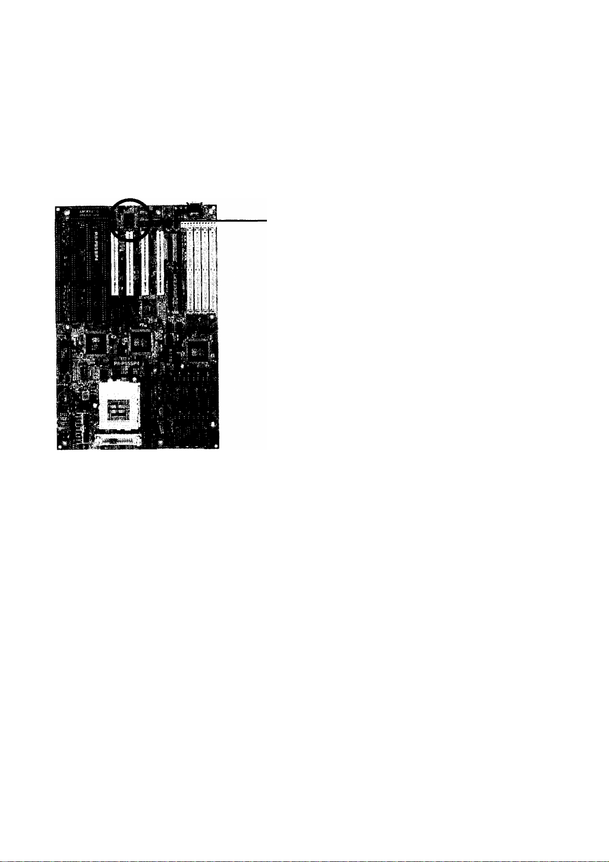
P/I-P55SP4
1.2 and later
1.22
2) Page 2-7: The two sentences, "DRAM Speed: 70ns or faster for 50, 60
or 66MHz external clock. EDO DRAM requires 60ns or faster for a
66MHz external clock setting."
Please change the above to the following:
DRAM speed requirements for both FP DRAM & EDO DRAM:
CPU internal clock (speed written on the CPU): 75, 90,120,150MH2
CPU external clock: 50 or 60MHz
Use 70ns or faster (the lower the number, the faster)
CPU internal clock (speed written on the CPU) 100,133,167MHz
CPU external clock: 66MHz
Use 60ns or faster (the lower the number, the faster)
3) Page 4-11: The note, "Note: The mainboard has no "Turbo" function,
so a switch will not work if you connect one. If you connect a casemounted Turbo LED, the LED will light while the system is turned on."
Please change the above to the following:
Note: This mainboard can support the Turbo On / Turbo Off switch
from the case. (Turbo Off decreases the speed of the system.)
P/I-P55SP4 User's Manual
TECHNICAL UPDATE
4) If you have a UMC Super Multi-I/O, the jumper setting for JPl A, JPl B,
and JPIC are no longer needed. On Page 4-7, the default settings for
JPl A, JPIB, and JPIC will be fixed on position 1-2.
The Infrared function on the UMC super multi-I/0 chip is enabled
through BIOS setup only, no hardware settings are necessary.
Check to see whether you have
a SMC Super Multi-I/O or a
UMC Super Multi-I/O. The
above applies to UMC only,
otherwise refer to page 4-7 for
UART2/IR Selection.
P/I-P55SP4 User's Manual

Copyright
This Product, Including Any Software And Documentation, May Not, In
Whole Or In Part, Be Copied, Photocopied, Translated Or Reduced To
Any Electronic Or Machine-Readable Form Without Prior Written Consent
From ASUSTek Computer Inc., Except For Copies Retained By The
Purchaser For Backup Purposes.
No Warranty Or Representation, Either Expressed Or Implied, Is Made
With Respect To This Documentation, Its Quality, Performance, Merchant
ability, Or Fitness For A Particular Purpose. As A Result, The Documenta
tion Is Licensed "'As Is," And The Licensee Will Assume The Entire Risk
As To Its Quality And Performance. This Work's Content Is Copyrighted
And Licensed To ASUSTek By Its Documentation Vendor And All Rights
Are Reserved. ASUSTek Reserves The Right To Revise This Work And
Any Accompanying Software And Documentation And To Make Changes
In The Content Without Obligation To Notify Any Person Or Organization
Of The Revision Or Change.
In No Event Will ASUSTek Be Liable For Direct, Indirect, Special, Inciden
tal, Or Consequential Damages Arising Out Of The Use Or Inability To
Use This Product Or Documentation Even If Advised Of The Possibility
Of Such Damages. In Particular, ASUSTek Shall Not Have Liability For
Any Hardware, Software, Or Data Stored Or Used With The Product,
Including The Costs Of Repairing, Replacing, Or Recovering Such
Hardware, Software Or Data.
Products Mentioned In This Manual Are Mentioned For Identification
Purposes Only. Product Names Appearing In This Manual May Or May
Not Be Registered Trademarks Or Copyrights Of Their Respective
Companies.
© Copyright 1995
User's Manual Rev 1.22
Related Mainboard; P/I-P55SP4 P.C.B. Rev 1.2 and up
Related BIOS: #401A0-0103 or up (# appears in upper left-hand
corner of screen at beginning of Power-On Boot-up)
Date: September 1995 ASUSTek Computer Inc.

Table of Contents
Chapter 1: Feature Guide............................................1-1
Main Features.........................................................................................1-2
Software.................................................................................................. 1-4
The P/I-P55SP4 Package
Static Electricity Precautions................................................................1-5
Mainboard Layout.................................................................................1-6
Using Your Mainboard.........................................................................1-8
.......................................................................
1-4
Hardware Settings
The System Configuration Record..............................................1-10
System IRQs...................................................................................1-11
BIOS-Supported Erthanced IDE Features
Large IDE Hard Disks............................................................1-13
Other IDE Devices
Dual IDE Channel Support
Faster Data Trcinsfer
Power Conservation
SCSI BIOS Firmware & The SC-200 Controller Card................1-14
..........................................................................
.................................
................................................................
...................................................
..............................................................
.....................................................................
1-13
1-8
1-12
1-13
1-14
1-14
Chapter 2: Upgrade Guide..........................................2-1
Installing Expansion Cards..................................................................2-2
Installation Procedure
Assigning System IRQs for Expansion Cards
Upgrading System Memory
Configuring System Memory
Installing SIMMs
Updating the Flash BIOS....................................................................2-10
....................................................................
.............................
................................................................
........................................................
.............................................................................
2-2
2-4
2-6
2-7
2-8
Chapter 3: Software Guide
Award BIOS Setup................................................................................ 3-1
Standard CMOS Setup....................................................................3-3
BIOS Features Setup
Chipset Features Setup
Power Management Setup...........................................................3-14
PCI/PNP & Onboard I/O Setup...................................................3-18
Load BIOS Defaults.......................................................................3-22
Load Setup Defaults
Setting Supervisor & User Passwords
.......................................................................
................................................,................
.....................................................................
.........................................
.......................................
3-1
3-8
3-12
3-23
3-24

P/I-P55SP4 User’s Manual
IDE HDD Auto E>etection
Save And Exit Setup.....................................................................3-27
Exit Without Saving
NCR SCSI BIOS & Drivers
. Flash Memory Writer Utility..............................................................3-29
.....................................................................
..........................................................
................................................................
3-25
3-27
3-28
Chapter 4: Technical Summary.................................4-1
Jumper Setting Summary....................................................................4-1
PS/2 Mouse Port Selector: JP5.......................................................4-1
SRAM Type Selector: JP6, JP7, JP8 & JP9
Level 2 Cache Size: JPIO & JPll.....................................................4-3
CPU External Clock Speed Selector: JP12, JP13 & JP14..............4-4
Flash Eprom Boot Block Write Selector: JP16.............................4-5
Flash Eprom Read/Write Selector: JP15
5-Volt/12-Volt EPROM Selector: JP17..........................................4-6
CPU Internal Clock Ext. Mulitple Selector: JP20 & JP21.... 4-6
Voltage Regulator Output Selector: JP22, JP23/JP28, JP29 4-7
Voltage Regulator Module Selector: JP32 - JP35
Level 2 Cache Options...................................................................4-8
External Connections.........................................................................4-10
Port & Controller Cables
Connecting A Power Supply
........................... .................................
......................................................
.....................................
......................................
.........................
4-2
4-5
4-7
4-12
4-13
The PCI-SC200 SCSI Interface Card.................................................4-14
Setting Up the PCI-SC200
SCSI ID Numbers.........................................................................4-18
...........................................................
4-15
IV

Feature Guide
This manual explains how to use this system mainboard and in
stall upgrades. It has an overview of the design and features of the
board and provides useful information if you want to change the
configuration of the board, or a system it is installed in.
How The Manual Is Organized
This manual is divided into four chapters:
Feature Guide - an overview of the board features
Upgrade Guide - upgrades for the board or system
Software Guide - the Setup Utility and other software & firmware
Technical Summary - technical reference
The manual assumes that your mainboard is already installed in
a computer system, so we've organized the contents to reflect this.
The first chapter introduces the mainboard's features and shows
where things are on the board in case you want to install an upgrade.
Chapter 2 explains how to install upgrades.
Chapter 3 explains the Award BIOS Setup Utility, SCSI BIOS and
the Flash Memory Writer BIOS update utility.
Chapter 4 lists settings and specifications and has instructions for
adding cache memory and the optional SCSI interface card.
1 -1

P/I-P55SP4 User's Manual
Since we are assuming that your mainboard is already installed
in a system, it was most likely set up by your system dealer accord
ing to the design specifications of your computer. This could mean
that your mainboard's current settings are not the same as the de
faults shown in this manual. Your system manual may have addi
tional information on how the mainboard should be set up.
If you want to change the existing configuration, consult all of
your system documentation. Also be certain that opening up and
working on the system yourself won't violate your system warranty.
Most system vendors do allow you to open the system to install ex
pansion cards or additional peripheral equipment.
This manual provides all the information you need to upgrade
or change the setup of the board. If you don't feel confident of your
ability to work on the computer yourself, ask your dealer or a quali
fied technician to do it for you.
Main Features
The P/I-P55SP4 has many performance and system features in
tegrated onto the mainboard, including the following:
• Supports 75, 90, 100, 120, 133 or 150MHz P54C/CS/CQS
Pentium CPUs in a ZIP (Zero Insertion Force) Socket 5 or 150
and 167MHz P55C Pentium CPUs in a ZIF Socket 7.
• SIS 551X chipset
• Uses 72-pin SIMM DRAM modules of 1MB to 128MB in mul
tiple configurations up to 512MB, with support for both Fast
Page Mode and Extended Data Output (EDO) SIMMs.
• Write-back "Level 2" external static RAM cache. There are two
cache options, SRAM sockets and a cache module socket. The
sockets for individual SRAM chips allow installation of 256KB,
512KB or 1MB of Asynchronous 15ns SRAM.
1-2

Feature Guide
If you install a cache module in the cache socket, the SRAM
sockets are disabled. Cache module options include 256KB,
512KB or 1MB of Pipelined SRAM.
Three 16-bit ISA and four 32-bit PCI expansion slots, with one
shared slot position. The PCI slots are Bus Master capable. In
addition to supporting standard PCI cards, the PCI4 slot also
has a proprietary slot extension which combines with it to form
the proprietary ASUSTek MediaBus slot.
BIOS support for Power management and "Plug and Play"
features and Enhanced ГОЕ, including support for up to four
ГОЕ hard disks or other ГОЕ devices and hard disks larger than
528MB and up to 8.4GB. Auto detection of installed IDE hard
disk drives via a utility built into the BIOS.
On-board 'Multi-I/O' using the NS 87C334 multi-I/O chip: 2
serial ports, 16550 Fast UART compatible; 1 parallel port with
EPP and ECP capabilities; all configurable as primary or sec
ondary COM and LPT ports; the second UART can support an
IrDA-compatible infrared port module attached to the 5-pin
onboard connector, instead of the COM2 port; the floppy disk
drive controller supports drives up to 2.88MB capacity.
On-board PCI Bus Master IDE controller with two coimectors
supports four IDE devices in two channels, faster data trans
fer rates and supports Enhanced IDE devices such as Tape
Backup and CD-ROM drives. The controller supports PIO'
Modes 3 and 4 at a maximum transfer rate of ITMB/second
and Bus Master IDE DMA Mode 2 at maximum 22MB/second.
Optional IrDA infrared port module and external PS/2 port
connector.
On-board NCR SCSI BIOS firmware supports the optional PCI
SC-200 SCSI controller card.
1-3

P/I-P55SP4 User’s Manual
Software
This mainboard comes support software, including software to
update the BIOS, and PCI Enhanced IDE device drivers. The driver
software disk has readme files on it that explain how to use the driver
software. The software includes:
• Flash Memory Writer — updates the system BIOS with a new
BIOS file.
• 5513 PCI IDE Drivers for the on-board PCI IDE:
Drivers for various operating systems and environments
Install program for DOS/Windows drivers
The P/I-P55SP4 Package
Your mainboard package comes with the following:
• The mainboard
• 1 IDE cable
• 1 Floppy Disk controller cable
• 1 Parallel port cable with port bracket
• 1 Serial port cable with double port bracket
• This manual
• Support floppy disks with the aforementioned software
• Optional External PS/2 mouse connector
1-4
• Optional External Infrared Module
If you purchased your mainboard as an upgrade, make sure
all of the items listed are present and undamaged. If you dis
cover a problem, contact your vendor immediately.

Feature Guide
If the mainboard came installed in a system, you should have
received the support floppy disks and this manual. In this case, the
drivers needed to support your particular system configuration may
already be installed on the system hard disk drive. If not, you should
install the ones you need.
Static Electricity Precautions
Under the right conditions, static electricity will build up. If you
touch the mainboard or other sensitive components, the build-up will
discharge into the components and circuitry. Computer components
are sensitive to damage from static electric discharge. They can be
damaged or destroyed if the discharge is powerful enough. Static
build-up is most likely to occur in dryer and cooler conditions, but
it is always important to be cautious.
To protect the mainboard and other components against damage
from static electric discharge, you should follow some basic precau
tions whenever you handle them:
1. Use a grounding wrist strap. The strap will have an 'alligator'
clip at the end of a shielded wire lead. Clip it to a grounded
object. Any static electricity will then harmlessly discharge
through the strap. Put on and connect the strap before you
handle the components.
2. Use an anti-static pad. Put any components on the pad when
ever you work on them outside the computer. If you don't have"
a pad, put the components on the anti-static bag they came in.
Both the wrist strap and pad are inexpensive and are generally
available from computer supply companies.
1-5
P/I-P55SP4 User's Manual
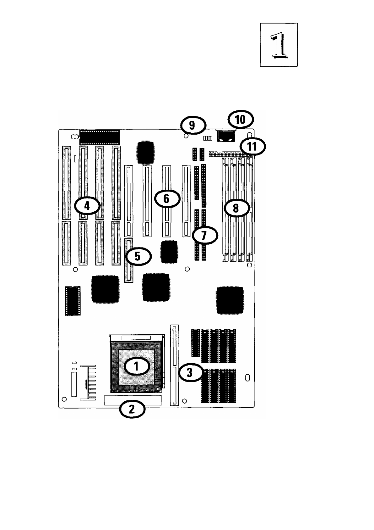
Mainboard Layout
The diagram on the next page shows the location of important
components on the mainboard. There are other small diagrams later
in the manual that point out the location of the topic being explained.
1. Pentium in ZIP Socket 5 or 7
2. VRM Header 7 Socket (used with Socket 7)
3.12 Cache module socket & chip sockets
4. ISA expansion slots
5. MediaBus (PCI+ISA) slot
6. PCI expansion slots
7. I/O, Floppy & IDE connectors
8. SIMM memory banks
9. PS/2 Mouse connector
10. Keyboard connector
11.5V power connector
1-6
P/I-P55SP4 Rev 1.1 Layout
Feature Guide
1-7

P/I-P55SP4 User's Manual
Using Your Mainboard
In addition to the operating instructions in your system manual,
there are a few additional things specific to the mainboard you will
need to know. These have to do with the hardware settings on the
mainboard and the system configuration record.
Hardware Settings
There are a number of hardware settings on the board. They
specify configuration options for various features. The settings are
made using something called a 'jumper'. Ajumper is a set of two or
more metal pins in a plastic base attached to the mainboard. A plas
tic jumper 'cap' with a metal plate inside fits over two pins to create
an electrical contact between them. The contact establishes a hard
ware setting.
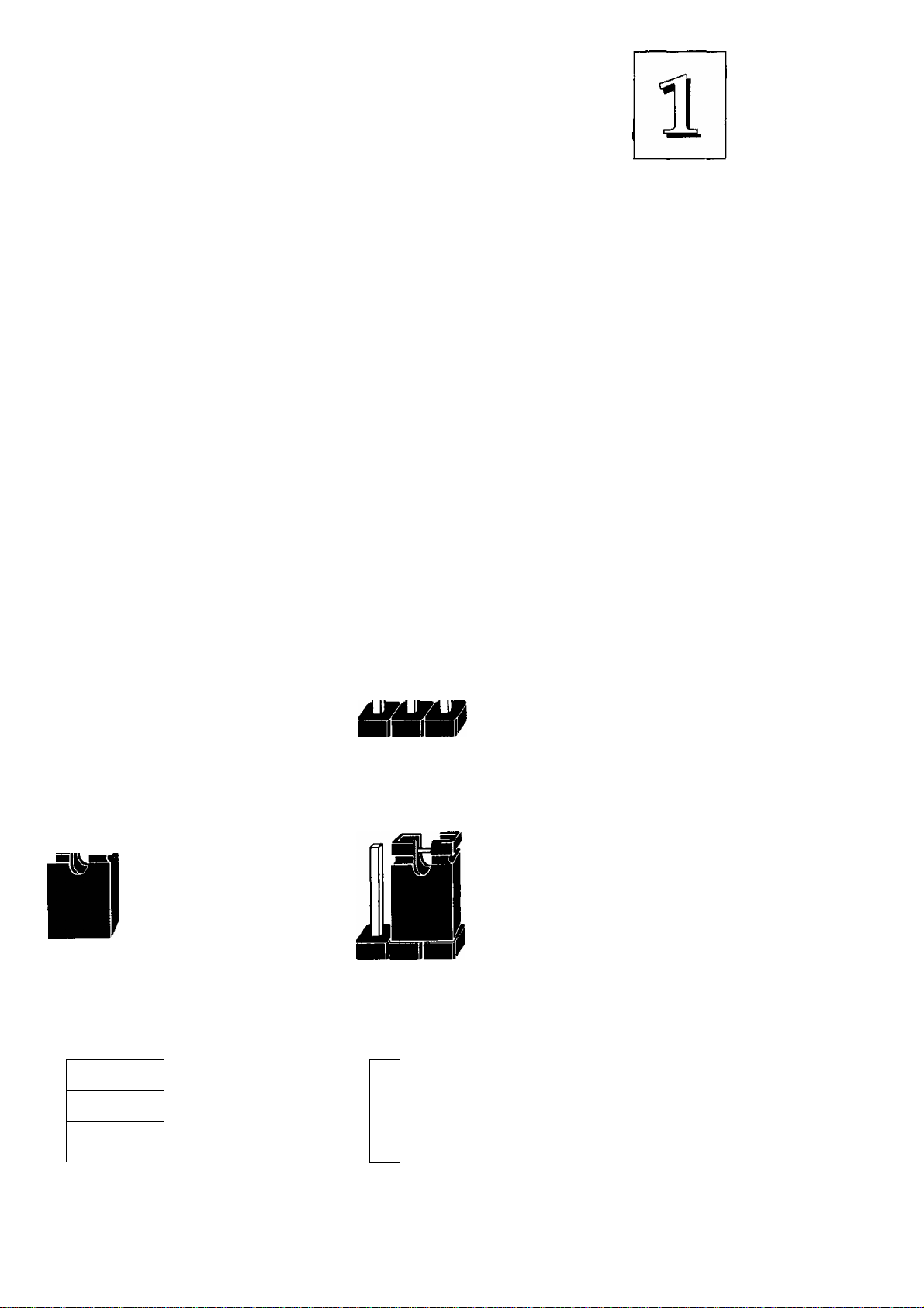
Some jumpers have two pins, others have three or more. The
jumpers are sometimes combined into sets called jumper 'blocks',
where all the jumpers in the block must be set together to establish a
hardware setting. The next figures show how this looks.
Jumpers and caps
Jumper cap 3-pin jumper 2-pin jumper Jumper block
1-8
Feature Guide
Setting options for most jumpers are printed on the board in a
stylized bird's-eye view, with which pins to connect for each setting
marked by a bar connecting two pins. For example, if a jumper has
three pins, connecting, or 'shorting', the first and second pins creates
one setting and shorting the second and third pins creates another.
The same type of diagrams are used in this manual. The jumpers are
always shown from the same point oi view as shown in the wholeboard diagram in this chapter. The next figures show what the
manual diagrams look like and what they represent.
Jumper diagrams
Jumpers are shown like this
O O
Jumper caps like this
i
o o o
Jumper settings like this
O 0-0
O 0-©
O Q-©
O
Jumpers in
a 'block'
Some jumpers are oriented
vertically; if the pin
4
position needs to be
o
shown. Pin 1 is marked.
1-9

P/I-P55SP4 User’s Manual
The System Configuration Record
All personal computers use a BIOS (Basic Input Output System)
as the basic software that tells the computer how to function. In or
der for the BIOS to function, there has to be a record of the computer's
hardware and configuration settings for it to refer to. This record is
created by using a software program that is permanently stored in
the BIOS ROM chip on the mainboard. The program is called the
Setup Utility.
The system configuration record the utility creates is also stored
on the mainboard. Unlike the utility program, the record is not re
corded permanently. The memory it gets stored in must be main
tained by battery power when the computer is turned off. If battery
support fails, the record will be lost and you will have to recreate it.
When you buy your computer, the system configuration record
will already be set. The settings will be optimized for your computer
hardware and may vary from the basic defaults. You should run the
Setup Utility when you first use your computer. Write down the set
tings. There is an explanation of how to run the Setup Utility in Chap
ter 3.
Important:
In some circumstances it is possible the configuration record may
be corrupted or lost. If this happens, your computer will not work
properly the next time you turn it on. This is not a serious problem.
To fix it, run the Setup Utility and re-enter your configuration from
your written record. When you restart the computer, it will work
normally
1-10

Feature Guide
System IRQs
Later in the manual you'll see something called an "IRQ" men
tioned several times. If you're not familiar with these, this is a short
explanation of what they are and why you may need to know about
them if you upgrade your system.
An IRQ, or interrupt request, is the process whereby an input or
output device tells the CPU to temporarily interrupt whatever it is
doing and immediately process something from the source of the
interrupt. When finished the CPU goes back to what it was already
processing. This happens very quickly. There are 16 IRQs, IRQ 0
through IRQ 15, in the ISA bus design. Devices that need an IRQ line
to operate sometimes must have the use of that line exclusively.
Many expansion cards require the use of an IRQ line to operate,
for example, network interface cards and sound cards. When you
install a card that uses an IRQ, it will have a default IRQ setting that
you might need to change if that IRQ is already in use and carmot be
shared. There are different ways of setting an IRQ assignment, with
jumpers being the most common.
Both the ISA bus and the PCI bus use the same set of system IRQs.
For the PCI bus there is an additional consideration. On the PCI bus,
you must assign an IRQ to the PCI slot you will install an IRQ-using
card in. There are two methods of generating an IRQ on the PCI bus,
level-triggering (level-sensitive) and edge-triggering. Most PCI ex
pansion cards use the level-triggered design. Some very few cards
may use the edge-triggered design instead. The mainboard design
therefore provides the means to set the IRQ assignment for a PCI slot
for either type of card, but performs this fimction automatically by
default. This is explained in detail in Chapters 2 & 3.
1-11

P/I-P55SP4 User's Manual
BIOS-Supported Enhanced IDE Features
The BIOS has several feature enhancements for IDE hard disk
drives and support for other IDE devices.
^ The original IDE implementation was limited to two hard disk
drives with relatively slower data transfer rates. While this solution
is simple and reliable, it has some limitations that have become more
significant as the performance level of other system components and
overall system performance have increased dramatically with the
advent of new microprocessor, expansion bus and operating system
technologies.
In response to these demands, the IDE specification has been
updated to increase its capabilities and provide improved perfor
mance. Together these are referred to as 'Enhanced IDE'. Enhanced
IDE features comprise the following:
• Support for IDE hard disk drives larger than the former 528MB
limit imposed by various technical factors.
• Support for IDE devices other than hard disk drives, includ
ing IDE Tape Backup and CD-ROM drives.
• Support for two IDE channels with two devices per channel,
allowing the use of four IDE devices in one system.
• Support for faster data transfer rates, particularly with IDE
controllers that have a PCI local bus interface.
This mainboard supports the use of these new features. The fea
tures work with the on-board PCI EIDE controller which has two con
nectors built onto the board. With this controller you can use one or
both connectors to connect up to four IDE devices.
1-12

Feature Guide
Large IDE Hard Disks
For IDE hard disk drives, the BIOS provides three modes to sup
port both normal IDE hard disks and also drives larger than 528MB:
Normal - for IDE drives smaller than 528MB
Large - for drives larger than 528MB that do not use LBA. These
can only be used with the MS-DOS operating system.
LBA - for drives larger than 528MB and up to 8.4 GB (GigaBytes)
that use Logic Block Addressing mode.
Other IDE Devices
Enhanced IDE allows the use of IDE devices other than hard
disks. Two devices that previously required non-standard or adapted
interfaces and are now available as standard IDE devices are Tape
Backup and CD-ROM drives. These will now be able to take advan
tage of the ease of installation, lower cost and in some cases superior
performance of Enhanced ГОЕ, putting an end to the system configu
ration complications created by their earlier interfaces.
To use IDE devices other than hard disks with this mainboard you
may need to install a device driver in your system software configu
ration. Refer to the documentation that comes with any device you
will install for instructions about this and any otther installation re
quirements.
Dual IDE Channel Support
With the on-board PCI IDE controller you can connect up to four
IDE peripheral devices to your system. With Enhanced IDE you can
connect two devices to each connector. All devices are categorized the
same way IDE hard disks have been in the past, with one device set
as the "Master'" device and the second as the "Slave" device.
1-13

P/I-P55SP4 User's Manual
Faster Data Transfer
Enhanced IDE includes a scheme to support a significant increase
in the rate of data transfer from the IDE device to the rest of the sys
tem compared to the previous standard. One aspect of this scheme
is support for the Mode 3 timing scheme. If you use both the on-board
controller and hard disks that support Mode 3 operation you can
increase the data transfer rate up to as much as 17MB per second.
Power Conservation
This mainboard incorporates the power conservation technology,
which you can set up in the BIOS Setup Utility, where the Power
Management Setup section controls the board's power management
scheme. The power management features include hard disk and
video controls. For more information see the section on Power Man
agement Setup in Chapter 3.
SCSI BIOS Firmware & The Optional SC-200 Controller Card
This mainboard has on-board NCR SCSI firmware recorded in the
BIOS flash ROM chip that supports the NCR 53C810 PCI Fast SCSI2 controller. There is an optional SCSI controller card, the SC-200 that
uses this firmware. The NCR SCSI controller is a full 32-bit PCI DMA
bus master and supports the ASPI and CAM standards.
You can connect a chain of up to seven devices to the SCSI inter
face. The SC-200 SCSI interface card provides both internal and ex
ternal connectors. There are details on this card and how to connect
SCSI devices to it at the end of Chapter 4.
Two floppy disks with support drivers come with the SC-200
card. There is detailed information about the drivers in "ReadMe"
files on the disks. There is more information about these disks in the
section on "SCSI BIOS & Drivers" in Chapter 3.
1-14
Upgrade Guide
This section explains how to install options on your mainboard.
It covers the most likely and technically accessible upgrades you
might want to do, including adding expansion cards, increasing sys
tem memory upgrading the BIOS.
Installing upgrades will either improve the performance of your
computer, or add some additional capabilities to it. You can install
upgrades yourself, or have your dealer or a qualified computer tech
nician do it for you.
It is also possible to increase the size of the Level 2 cache for the
SRAM cache model, but since this is a much more technically de
manding upgrade that you are both less likely to undertake, and in
most cases would probably require at least partially disassembling
your system, the technical reference information about this is in Chap
ter 4. It is probably best to have a qualified technician perform the
upgrade for you if you want to upgrade the cache.
2-1

P/I-P55SP4 User's Manual
Installing Expansion Cards
There many ISA and PCI expansion cards you can install in your
system to expand its capabilities. Any card you get will come with
instructions on how to configure and install it. For your reference,
we have included a brief decsription here of how to install a card in
your system case. This is followed by an explanation of this
mainboard's requirements for installing expansion cards that use an
interrupt request line (IRQ). Please review the IRQ information care
fully if you are installing this type of card. If you're more familiar with
this topic, there is a chart-based synopsis of the required procedures
at the end of this section.
Installation Procedure
Expansion cards often require pre-installation configuration and
sometimes post-installation software setup. Check your card docu
mentation for instructions on this. Once you have configured an ex
pansion card you want to install, the installation procedure is fairly
simple. Your system manual should have instructions for installing
expansion cards specific to the design of your system case. The pro
cedure here covers the basics for your reference.
Before you start, always make sure the computer is turned off.
You should also make sure to observe standard static electricity dis
charge precautions. You can damage your expansion card, the
mainboard, or both by not being careful about this.
The basic procedure for installing expansion cards is the same for
both ISA and PCI cards. The components on ISA cards will face to
the right as you view the computer from the front. PCI card compo
nents face to the left. Please note that the PCI Slot 4/MediaBus Slot
and ISA Slot 1 share the same mounting bracket position, so you
can only use one of these slots, not both.
2-2

upgrade Guide
The basic procedure is as follows:
1. Open the system case to gain access to the expansion slots.
2. Remove the slot-cover corresponding to the slot you want plan
to use. Put the slot-cover retaining screw aside and store the
slot cover in case you need it later.
3. Remove the card from its protective packaging if you haven't
already.
4. Align the card's slot connectors to the slot. Keep the card at a
90° angle to the mainboard. Insert the card into the slot by
pressing it firmly downward. If there is a lot of resistance, make
sure the slot connectors are lined up correctly. PCI cards require
very little pressure to insert.
5. Attach the card's mounting bracket to the case using the slot
cover screw you put aside in Step 2.
6. Close the case, turn on the computer and check to see if the
card is working properly as well as do any software set up re
quired.
Use the screw to
secure the card to
Remove the slot
retaining screw
& slot cover
the case
j
The component side of the card should face right (or
up) for an ISA card and left (or down) for a PCI card
/
2-3

P/I-P55SP4 User's Manual
Assigning System IRQs for Expansion Cards
Some expansion cards need to use an IRQ to operate. Generally
an IRQ must be exclusively assigned to one use. As mentioned in
Chapter 1, there are 16 IRQs available. In an standard design, some
of them are already in use by parts of the system such as the keyboard
or mouse. Expansion cards that need to use an IRQ then draw from
the unused group of System IRQs.
Both ISA and PCI expansion cards may need to use IRQs. Sys
tem IRQs are available to cards installed in the ISA expansion bus
first, and any remaining can be used by cards installed on the PCI bus.
Currently, there are two types of ISA cards. The original ISA expan
sion card design, now referred to as "Legacy" ISA cards, requires that
you configure the card hardware manually and then install it in any
available slot on the ISA bus. Under this scheme, you must ensure
that the installed cards do not conflict with each other by using the
same IRQ. This process requires careful manual system configuration
to avoid conflicts that prevent the system from working properly.
To address this problem, the Plug and Play specification was
developed to allow automatic system configuration whenever a Plug
and Play-compliant card is added to the system. For Plug and Play
(PNP) cards, IRQs are assigned automatcally from those available.
If the system has both Legacy and PNP ISA cards installed, IRQs
are assigned to PNP cards from the IRQs not already hardware as
signed to the Legacy cards. In this case, you can establish the system
confguration in one of two ways. If you have an ISA Configuration
Utility, you can use it to indicate which IRQs are in use by Legacy
cards. If you do not have an ICU program, you can use the PCI and
PNP Configuration of the BIOS Setup utility to indicate which IRQs
are being used by Leagacy cards. Refer to Chapter 3 for information
on how to do this.
2-4

upgrade Guide
Any PCI expansion cards that need to use an IRQ have one au
tomatically assigned from the IRQs remaining after Legacy and PNP
ISA cards have had theirs assigned. In the PCI bus design, the BIOS
automatically assigns an IRQ to a PCI slot that has a card in it that
requires an IRQ. To install a PCI card, you need to set something
called the "INT" assignment. Since all the PCI slots on this mainboard
use "INTA#", you only need to make sure that any PCI card you in
stall is set to INT A.
Assigning DMA Channels For ISA Cards
Some ISA cards, both Legacy and PNP may also need to use a
DMA (Direct Memory Access) channel. DMA assignments for this
mainboard are handled the same way as the IRQ assignment process
described above. If you don't use an ICU program, you can select a
DMA channel in the PCI and PNP Configuration section of the BIOS
Setup utility.
The MediaBus Slot
The PCM slot is both a standard PCI slot and, combined with its
slot extension, forms a proprietary MediaBus slot for ASUSTek
MediaBus expansion cards. The slot extension is an ISA extension that
allows combining of a PCI card and an 16-bit ISA card on one com
posite card. Review the documentation for a particular card for an
explaination of how to install and set it up, including any IRQ use.
2-5

P/I-P55SP4 User's Manual
Upgrading System Memory
This section explains how to install system memory. There are
instructions on how to configure and install memory and an expla
nation of the technical specifications required.
System DRAM is the main source of data for the CPU. Data re
mains stored in DRAM as long as the system is turned on, and is lost
when you turn it off. The Level 2 cache memory is Static RAM
(SRAM), which is faster than DRAM memory. When the CPU looks
for data, it first searches the cache. If the information is not there, the
search continues in the DRAM. With this design, the CPU looks in
the fastest source of data first, which lets it operate as fast as possible.
The DRAM subsystem uses memory chips permanently mounted
on small circuit boards to form ''SIMMs" (Single In-line Memory
Modules). The memory chips have a speed rating that is measured
in nanoseconds (ns). This mainboard requires either Fast Page Mode
(FPM) DRAM or Extended Data Output (EDO) DRAM with a speed
of at least 70ns.
This mainboard can use 72-pin SIMMs in four sizes from 1MB up
to 128MB (megabytes). Depending on the combination of modules
you use, you can install between 2MB and512MB. The 32-bit mod
ules used for this board come with memory chips on either one or
both sides of the module.
IMPORTANT: Do not use SIMM modules with more than 24 chips
per module with this mainboard. Modules with more than 24 chips
exceed the design specifications of the memory subsystem and will
cause unreliable operation. DO NOT use 32 or 36-chip modules with
this mainboard.
2-6
 Loading...