


Asus P4P800 User Manual

P4P800
Deluxe
User Guide
Motherboard

E1323
Revised Edition V3
May 2003
Copyright © 2003 ASUSTeK COMPUTER INC. All Rights Reserved.
No part of this manual, including the products and software described in it, may be
reproduced, transmitted, transcribed, stored in a retrieval system, or translated into any
language in any form or by any means, except documentation kept by the purchaser for
backup purposes, without the express written permission of ASUSTeK COMPUTER INC.
(“ASUS”).
Product warranty or service will not be extended if: (1) the product is repaired, modified or
altered, unless such repair, modification of alteration is authorized in writing by ASUS; or (2)
the serial number of the product is defaced or missing.
ASUS PROVIDES THIS MANUAL “AS IS” WITHOUT WARRANTY OF ANY KIND, EITHER
EXPRESS OR IMPLIED, INCLUDING BUT NOT LIMITED TO THE IMPLIED WARRANTIES
OR CONDITIONS OF MERCHANTABILITY OR FITNESS FOR A PARTICULAR PURPOSE.
IN NO EVENT SHALL ASUS, ITS DIRECTORS, OFFICERS, EMPLOYEES OR AGENTS BE
LIABLE FOR ANY INDIRECT, SPECIAL, INCIDENTAL, OR CONSEQUENTIAL DAMAGES
(INCLUDING DAMAGES FOR LOSS OF PROFITS, LOSS OF BUSINESS, LOSS OF USE
OR DATA, INTERRUPTION OF BUSINESS AND THE LIKE), EVEN IF ASUS HAS BEEN
ADVISED OF THE POSSIBILITY OF SUCH DAMAGES ARISING FROM ANY DEFECT OR
ERROR IN THIS MANUAL OR PRODUCT.
SPECIFICATIONS AND INFORMATION CONTAINED IN THIS MANUAL ARE FURNISHED
FOR INFORMATIONAL USE ONLY, AND ARE SUBJECT TO CHANGE AT ANY TIME
WITHOUT NOTICE, AND SHOULD NOT BE CONSTRUED AS A COMMITMENT BY ASUS.
ASUS ASSUMES NO RESPONSIBILITY OR LIABILITY FOR ANY ERRORS OR
INACCURACIES THAT MAY APPEAR IN THIS MANUAL, INCLUDING THE PRODUCTS
AND SOFTWARE DESCRIBED IN IT.
Products and corporate names appearing in this manual may or may not be registered
trademarks or copyrights of their respective companies, and are used only for identification or
explanation and to the owners’ benefit, without intent to infringe.
ii

Contents
FCC/CDC statements.....................................................................vi
Safety information ......................................................................... vii
About this guide............................................................................ viii
How this guide is organized ................................................ viii
Conventions used in this guide .............................................ix
Where to find more information .............................................ix
ASUS contact information ...............................................................x
P4P800 Deluxe specifications summary ........................................xi
Chapter 1: Product introduction
1.1 Welcome! ........................................................................... 1-1
1.2 Package contents............................................................... 1-1
1.3 Special features.................................................................. 1-2
1.3.1 Product highlights .................................................. 1-2
1.3.2 Value-added solutions............................................ 1-6
1.4 Motherboard overview........................................................ 1-7
1.4.1 Major components ................................................. 1-7
1.4.2 Core specifications ................................................ 1-9
Chapter 2: Hardware information
2.1 Motherboard installation ..................................................... 2-1
2.1.1 Placement direction ............................................... 2-1
2.1.2 Screw holes ........................................................... 2-1
2.2 Motherboard layout ............................................................ 2-2
2.3 Before you proceed ............................................................ 2-3
2.4 Central Processing Unit (CPU)........................................... 2-4
2.4.1 Overview ................................................................ 2-4
2.4.2 Installing the CPU .................................................. 2-5
2.4.3 Installing the heatsink and fan ............................... 2-7
2.4.4 Connecting the CPU fan cable .............................. 2-9
2.5 System memory ............................................................... 2-10
2.5.1 Overview .............................................................. 2-10
2.5.2 Memory configurations .........................................2-11
2.5.3 Installing a DIMM ................................................. 2-14
2.5.4 Removing a DIMM ............................................... 2-14
2.6 Expansion slots ................................................................ 2-15
2.6.1 Installing an expansion card ................................ 2-15
2.6.2 Configuring an expansion card ............................ 2-15
2.6.3 PCI slots .............................................................. 2-17
2.6.4 AGP slot............................................................... 2-18
2.6.5 WiFi slot ............................................................... 2-19
2.7 Jumpers............................................................................ 2-20
2.8 Connectors ....................................................................... 2-23
iii

Contents
Chapter 3: Powering up
3.1 Starting up for the first time ................................................ 3-1
3.2 Vocal POST Messages ...................................................... 3-2
3.3 Powering off the computer ................................................. 3-4
Chapter 4: BIOS setup
4.1 Managing and updating your BIOS .................................... 4-1
4.1.1 Creating a bootable floppy disk ............................. 4-1
4.1.2 Using AFUDOS to update the BIOS ...................... 4-1
4.1.3 Using AFUDOS to copy BIOS from PC ................. 4-3
4.1.4 Using ASUS EZ Flash to update the BIOS ............ 4-4
4.1.5 Recovering the BIOS with CrashFree BIOS 2 ....... 4-5
4.2 BIOS Setup program .......................................................... 4-7
4.2.1 BIOS menu screen ................................................ 4-8
4.2.2 Menu bar................................................................ 4-8
4.2.3 Navigation keys ..................................................... 4-8
4.2.4 Menu items ............................................................ 4-9
4.2.5 Sub-menu items..................................................... 4-9
4.2.6 Configuration fields ................................................ 4-9
4.2.7 Pop-up window ...................................................... 4-9
4.2.8 Scroll bar................................................................ 4-9
4.2.9 General help .......................................................... 4-9
4.3 Main menu........................................................................ 4-10
4.3.1 System Time [xx:xx:xxxx]..................................... 4-10
4.3.2 System Date [Day xx/xx/xxxx] ............................. 4-10
4.3.3 Legacy Diskette A [1.44M, 3.5 in.] ....................... 4-10
4.3.4 Language [English] .............................................. 4-10
4.3.5 Primary and Secondary IDE Master/Slave; Third .......
and Fourth IDE Master .........................................4-11
4.3.6 IDE Configuration ................................................ 4-12
4.3.7 System Information .............................................. 4-14
4.4 Advanced menu ............................................................... 4-15
4.4.1 JumperFree Configuration ................................... 4-15
4.4.2 CPU Configuration ............................................... 4-18
4.4.3 Chipset................................................................. 4-18
4.4.4 Onboard Devices Configuration........................... 4-20
4.4.5 PCI PnP ............................................................... 4-22
4.4.6 USB Configuration ............................................... 4-23
4.4.7 Speech Configuration .......................................... 4-25
4.4.8 Instant Music Configuration ................................. 4-26
4.5 Power menu ..................................................................... 4-27
4.5.1 Suspend Mode [Auto] .......................................... 4-27
4.5.2 Repost Video on S3 Resume [No] ....................... 4-27
4.5.3 ACPI 2.0 Support [No] ......................................... 4-27
4.5.4 ACPI APIC Support [Enabled] ............................. 4-27
4.5.5 BIOS -> AML ACPI Table [Enabled] ..................... 4-27
iv

Contents
4.5.6 APM Configuration............................................... 4-28
4.5.7 Hardware Monitor ................................................ 4-30
4.6 Boot menu ........................................................................ 4-32
4.6.1 Boot Device Priority ............................................. 4-32
4.6.2 Hard disk drives ................................................... 4-33
4.6.3 Boot Settings Configuration ................................. 4-33
4.6.4 Security ................................................................ 4-35
4.7 Exit menu ......................................................................... 4-37
Chapter 5: Software support
5.1 Install an operating system................................................. 5-1
5.2 Support CD information...................................................... 5-1
5.2.1 Running the support CD ........................................ 5-1
5.2.2 Drivers menu ......................................................... 5-2
5.2.3 Utilities menu ......................................................... 5-3
5.2.4 ASUS Contact Information..................................... 5-4
5.2.5 Other information ................................................... 5-5
5.3 Software information .......................................................... 5-7
5.3.1 ASUS Update ........................................................ 5-7
5.3.2 ASUS MyLogo2™.................................................. 5-8
5.3.3 ASUS PC Probe .................................................. 5-10
5.3.4 ASUS Instant Music ............................................. 5-14
5.3.5 Winbond Voice Editor .......................................... 5-17
5.3.6 SoundMAX
®
4 XL software .................................. 5-21
5.4 RAID 0/ RAID 1/ RAID 0+1 / JBOD configurations .......... 5-25
5.4.1 Install the hard disks ............................................ 5-26
®
5.4.2 Enter the VIA
Tech RAID BIOS utility ................. 5-27
5.4.3 Create Array......................................................... 5-28
5.4.4 Delete Array ......................................................... 5-32
5.4.5 Create/Delete Spare ............................................ 5-32
5.4.6 Select Boot Array ................................................. 5-33
5.4.7 Serial Number View ............................................. 5-33
®
5.5 Intel
RAID for Serial ATA configurations.......................... 5-34
5.5.1 BIOS Configuration .............................................. 5-34
5.5.2 Installing Serial ATA hard disks ............................ 5-34
5.5.3 Creating, Deleting and Resetting RAID sets........ 5-35
5.5.4 Creating a RAID Volume...................................... 5-35
5.5.5 Deleting a RAID Volume ...................................... 5-36
5.5.6 Reset RAID Data ................................................. 5-37
®
5.6 Using Intel
5.7 Marvell
/ VIA® Makedisk.exe ...................................... 5-38
®
Virtual Cable Tester™ (VCT) Technology........... 5-39
v

FCC/CDC statements
Federal Communications Commission Statement
This device complies with FCC Rules Part 15. Operation is subject to the
following two conditions:
• This device may not cause harmful interference, and
• This device must accept any interference received including interference
that may cause undesired operation.
This equipment has been tested and found to comply with the limits for a
Class B digital device, pursuant to Part 15 of the FCC Rules. These limits
are designed to provide reasonable protection against harmful interference
in a residential installation. This equipment generates, uses and can radiate
radio frequency energy and, if not installed and used in accordance with
manufacturer’s instructions, may cause harmful interference to radio
communications. However, there is no guarantee that interference will not
occur in a particular installation. If this equipment does cause harmful
interference to radio or television reception, which can be determined by
turning the equipment off and on, the user is encouraged to try to correct the
interference by one or more of the following measures:
• Reorient or relocate the receiving antenna.
• Increase the separation between the equipment and receiver.
• Connect the equipment to an outlet on a circuit different from that to
which the receiver is connected.
• Consult the dealer or an experienced radio/TV technician for help.
The use of shielded cables for connection of the monitor to the
graphics card is required to assure compliance with FCC regulations.
Changes or modifications to this unit not expressly approved by the
party responsible for compliance could void the user’s authority to
operate this equipment.
Canadian Department of Communications Statement
This digital apparatus does not exceed the Class B limits for radio noise
emissions from digital apparatus set out in the Radio Interference
Regulations of the Canadian Department of Communications.
This class B digital apparatus complies with Canadian ICES-003.
vi

Safety information
Electrical safety
• To prevent electrical shock hazard, disconnect the power cable from
the electrical outlet before relocating the system.
• When adding or removing devices to or from the system, ensure that
the power cables for the devices are unplugged before the signal
cables are connected. If possible, disconnect all power cables from the
existing system before you add a device.
• Before connecting or removing signal cables from the motherboard,
ensure that all power cables are unplugged.
• Seek professional assistance before using an adpater or extension
cord. These devices could interrupt the grounding circuit.
• Make sure that your power supply is set to the correct voltage in your
area. If you are not sure about the voltage of the electrical outlet you
are using, contact your local power company.
• If the power supply is broken, do not try to fix it by yourself. Contact a
qualified service technician or your retailer.
Operation safety
• Before installing the motherboard and adding devices on it, carefully
read all the manuals that came with the package.
• Before using the product, make sure all cables are correctly connected
and the power cables are not damaged. If you detect any damage,
contact your dealer immediately.
• To avoid short circuits, keep paper clips, screws, and staples away from
connectors, slots, sockets and circuitry.
• Avoid dust, humidity, and temperature extremes. Do not place the
product in any area where it may become wet.
• Place the product on a stable surface.
• If you encounter technical problems with the product, contact a
qualified service technician or your retailer.
vii

About this guide
This user guide contains the information you need when installing the
ASUS P4P800 Deluxe motherboard.
How this guide is organized
This manual contains the following parts:
• Chapter 1: Product introduction
This chapter describes the features of the P4P800 Deluxe
motherboard. It includes brief descriptions of the special attributes of
the motherboard and the new technology it supports.
• Chapter 2: Hardware information
This chapter lists the hardware setup procedures that you have to
perform when installing system components. It includes description of
the switches, jumpers, and connectors on the motherboard.
• Chapter 3: Powering up
This chapter describes the power up sequence and gives information
on the BIOS beep codes.
• Chapter 4: BIOS setup
This chapter tells how to change system settings through the BIOS
Setup menus. Detailed descriptions of the BIOS parameters are also
provided.
• Chapter 5: Software support
This chapter describes the contents of the support CD that comes with
the motherboard package.
viii

Conventions used in this guide
To make sure that you perform certain tasks properly, take note of the
following symbols used throughout this manual.
WARNING: Information to prevent injury to yourself when trying
to complete a task.
CAUTION: Information to prevent damage to the components
when trying to complete a task.
IMPORTANT: Information that you MUST follow to complete a
task.
NOTE: Tips and additional information to aid in completing a task.
Where to find more information
Refer to the following sources for additional information and for product
and software updates.
1. ASUS Websites
The ASUS websites worldwide provide updated information on ASUS
hardware and software products. The ASUS websites are listed in the
ASUS Contact Information on page x.
2. Optional Documentation
Your product package may include optional documentation, such as
warranty flyers, that may have been added by your dealer. These
documents are not part of the standard package.
ix

ASUS contact information
ASUSTeK COMPUTER INC. (Asia-Pacific)
Address: 150 Li-Te Road, Peitou, Taipei, Taiwan 112
General Tel: +886-2-2894-3447
General Fax: +886-2-2894-3449
General Email: info@asus.com.tw
Technical Support
MB/Others (Tel): +886-2-2890-7121 (English)
Notebook (Tel): +886-2-2890-7122 (English)
Desktop/Server (Tel): +886-2-2890-7123 (English)
Support Fax: +886-2-2890-7698
Web Site: www.asus.com.tw
ASUS COMPUTER INTERNATIONAL (America)
Address: 44370 Nobel Drive, Fremont, CA 94538, USA
General Fax: +1-502-933-8713
General Email: tmd1@asus.com
Technical Support
Support Fax: +1-502-933-8713
General Support: +1-502-995-0883
Notebook Support: +1-510-739-3777 x5110
Web Site: www.asus.com
Support Email: tsd@asus.com
ASUS COMPUTER GmbH (Germany and Austria)
Address: Harkortstr. 25, 40880 Ratingen, BRD, Germany
General Email: sales@asuscom.de (for marketing requests only)
General Fax: +49-2102-9599-31
Technical Support
Support Hotlines: (Components) +49-2102-9599-0
(Notebook PC) +49-2102-9599-10
Support Fax: +49-2102-9599-11
Support Email: www.asuscom.de/kontakt (for online support)
Web Site: www.asuscom.de
x

P4P800 Deluxe specifications summary
CPU
CPU
Chipset
Chipset
Front Side Bus (FSB)
Front Side Bus (FSB)
Memory
Memory
Expansion slots
Expansion slots
IDE
Storage
RAID IDE / Serial ATA
(optional)
IEEE 1394 (optional)
Socket 478 for Intel® Pentium® 4 / Celeron up to 3.06 GHz+
Supports Intel
Supports Intel® Prescott CPU
North Bridge: Intel 82865PE
South Bridge: Intel ICH5R w/ RAID 0 support
800/533/400 MHz
Dual-channel memory architecture
Supports PC3200/2700/2100 unbuffered non-ECC DDR
DIMMs
4 x 184-pin DDR DIMM sockets for up to 4GB memory
1 x AGP 8X (1.5V only)
5 x PCI
1 x WiFi slot
Supported by South Bridge (ICH5R)
- 2 x UltraDMA100 support for 4 drives
- 2 x Serial ATA with RAID 0 function
Supported by VIA
- 2 x UltraDMA 133 connector support for 4 drives with
RAID 0, RAID 1, RAID 0+1 and RAID JBOD
®
Hyper-Threading Technology
®
6410 RAID controller
IEEE 1394
Audio (optional)
LAN (optional)
AI Audio
AI Net
AI BIOS
AI Overclocking
Special features
VIA 6307
2 x IEEE 1394 ports
ADI AD1985 6-channel audio CODEC
1 x S/PDIF out
3COM 3C940 Gbit PCI LAN controller
AI BIOS solutions: ASUS CrashFree BIOS 2
ASUS Q-Fan Technology
ASUS POST Reporter™
Intelligent CPU frequency tuner
ASUS JumperFree
Adjustable CPU V
SFS (Stepless Frequency Selection) from 100MHz to
400MHz at 1MHz increments
C.P.R. (CPU Parameter Recall)
ASUS MyLogo 2
Instant Music
ASUS EZ Flash
Multi-language BIOS
, memory and AGP voltages
CORE
(continued on the next page)
xi

P4P800 Deluxe specifications summary
Special features
Rear Panel I/O
Internal I/O
Rear panel I/O
BIOS features
Internal I/O
1 x Parallel port
1 x Serial ports
1 x PS/2 keyboard port
1 x PS/2 mouse port
4 x USB 2.0/USB 1.1 ports
1 x RJ-45 port (optional)
1 x S/PDIF-out port
1 x IEEE 1394 port
Line In/Line Out/Microphone ports
2 x USB 2.0/1.1 connector for 4 additional USB ports
CPU/Chassis/Power fan connectors
20-pin/4-pin ATX 12V power connectors
Chassis intrusion
1 x IEEE 1394 connectors
GAME connector
S/PDIF out connector
CD/AUX/Modem audio connectors
Front panel audio connector
COM2 connector
4Mb Flash ROM, AMI BIOS, PnP, DMI2.0, ACPI, SM
BIOS2.3, CrashFree BIOS 2, Multi-language BIOS, ASUS
EZ Flash, ASUS MyLogo2, ASUS Instant Music
Industry standard
Manageability
Form Factor
Support CD contents
BIOS features
* Specifications are subject to change without notice.
Industry standard
Manageability
Form Factor
Support CD contents
USB 2.0, PCI 2.2 (PCI 2.3)
DMI 2.0, WOL/WOR by PME, WO_USB, WO_KB/MS,
chassis intrusion
ATX form factor: 12 in x 9.6 in
Device drivers
ASUS PC Probe
ASUS LiveUpdate
Trend Micro™ PC-cillin 2002 anti-virus software
xii
Chapter 1
This chapter describes the features of the
P4P800 Deluxe motherboard. It includes
brief explanations of the special attributes of
the motherboard and the new technology it
supports.
Product introduction

Chapter summary
1.1 Welcome! ........................................................ 1-1
1.2 Package contents .......................................... 1-1
1.3 Special features ............................................. 1-2
1.4 Motherboard overview................................... 1-7
ASUS P4P800 Deluxe motherboard

1.1 Welcome!
Thank you for buying the ASUS
®
P4P800 Deluxe motherboard!
The ASUS
and latest technologies making it another standout in the long line of
ASUS quality motherboards!
The P4P800 Deluxe incorporates the Intel
pin package coupled with Intel® 82865PE and ICH5R chipsets that
support the fastest 800MHz FSB to set a new benchmark for an effective
desktop platform solution.
Supporting up to 4GB of system memory with PC3200/2700/2100 DDR
SDRAM, high-resolution graphics via an AGP 8X slot, Serial ATA support,
RAID, IEEE 1394, USB 2.0, and 6-channel audio features, the P4P800
Deluxe is your perfect tool to get ahead in the world of power computing!
Before you start installing the motherboard, and hardware devices on it,
check the items in your package with the list below.
P4P800 Deluxe motherboard delivers a host of new features
®
Pentium® 4 Processor in 478-
1.2 Package contents
Check your P4P800 Deluxe package for the following items.
ASUS P4P800 Deluxe motherboard
ASUS support CD
2 x SATA cable
80-conductor ribbon cables for UltraDMA/66/100 IDE drives
40-conductor IDE cable
Ribbon cable for a 3.5-inch floppy drive
I/O shield
Bag of extra jumper caps
User Guide
Quick Reference Card (last page of User Guide)
Quick Setup Guide (retail boxes only)
Jumpers and Connectors Sticker (retail boxes only)
WinDVD Suite software
Instant Music keyboard label (retail boxes only)
If any of the above items is damaged or missing, contact your retailer.
ASUS P4P800 Deluxe motherboard user guide
1-1

1.3 Special features
1.3.1 Product highlights
Latest processor technology
The P4P800 Deluxe motherboard supports the latest Intel
Celeron Processor via a 478-pin surface mount ZIF socket. The Pentium 4
processor with 512KB L2 cache on 0.13 micron processor includes a 800/
533/400 MHz system bus and the FMB2 power design that allows up to
3.06+ GHz core frequencies and Intel® Prescott CPU when available. See
page 2-4 for more information.
®
Pentium® 4 /
Dual Channel DDR memory support
Employing the dual channel Double Data Rate (DDR) memory architecture,
the P4P800 Deluxe motherboard supports up to 4GB of system memory
using PC3200/2700/PC2100 DDR DIMMs. The ultra-fast 400MHz memory
bus that delivers the required bandwidth for the latest multimedia, internet,
and 3D graphics applications. See page 2-10.
Serial ATA solution, RAID 0 support
The motherboard supports two interfaces compliant to the Serial ATA
(SATA) specification, an evolutionary replacement of the Parallel ATA
storage interface. The Serial ATA specification allows for thinner, more
flexible cables with lower pin count, reduced voltage requirement, up to
150 MB/s data transfer rate. With the Intel
motherboard supports RAID 0 configuration using SATA drives.
®
ICH5R controller onboard, the
Ai NET solution
The Ai Series supports Gigabit LAN by integrating the 3Com
controller, equipped with a unique net-diagnosing utility - VCT (Virtual
Cable Tester). VCT intelligently diagnoses and reports cable faults from a
remote location up to 100 meters and helps users improve network quality.
See page 5-39.
®
3C940
AGP 8X support
AGP 8X (AGP 3.0) is the next generation VGA interface specification that
enables enhanced graphics performance with high bandwidth speeds up
to 2.12 GB/s.
1-2
Chapter 1: Product introduction

Ai Audio solution
The SoundMAX-class ADI AD1985 AC ‘97 audio CODEC supports
6-channel 5.1 surround sound output, stereo microphone input, variable
sample rate conversion (SRC), professional quality 103-dB out put with
94-dB SNR, and analog enumeration capability. The SoundMAX 4 XL
software features the AudioESP™ (Audio Enumeration and Sensing
Process) that allows intelligent detection of the peripherals plugged into
the audio ports and identifies the incompatible devices, if any.
See page 5-21
Ai BIOS solution
The Ai BIOS is a combination of three ASUS intelligent solutions:
CrashFree BIOS2, Q-Fan technology and POST Reporter.
Dual Channel UltraATA 133 RAID support
This motherboard incorporates the high-performance VIA
RAID controller, which supports RAID 0, RAID 1, RAID 0+1 and JBOD for
a balance of hard disk performance and data protection.
®
VT6410 IDE
IEEE 1394 support
The IEEE 1394 interface provides high-speed and flexible PC connectivity
to a wide range of peripherals and devices compliant to IEEE 1394a
standards. The IEEE 1394 interface allows up to 400Mbps transfer rates
through simple, low-cost, high-bandwidth asynchronous (real-time) data
interfacing between computers, peripherals, and consumer electronic
devices such as camcorders, VCRs, printers,TVs, and digital cameras.
See page 2-32.
USB 2.0 technology
The motherboard implements the new Universal Serial Bus (USB) 2.0
specification, extending the connection speed from 12 Mbps on USB 1.1
to a fast 480 Mbps on USB 2.0 - supporting up to 8 USB 2.0 ports. The
higher bandwidth of USB 2.0 allows connection of devices such as high
resolution video conferencing cameras, next generation scanners and
printers, and fast storage units. USB 2.0 is backward compatible with USB
1.1. See page 2-30.
ASUS P4P800 Deluxe motherboard user guide
1-3

C.P.R. (CPU Parameter Recall)
The C.P.R. feature of the motherboard BIOS allows automatic re-setting to
the BIOS default settings in case the system hangs due to overclocking.
When the system hangs due to overclocking, C.P.R. eliminates the need to
open the system chassis and clear the RTC data. Simply shut down and
reboot the system, and BIOS automatically restores the CPU default
setting for each parameter.
ASUS POST Reporter
P4P800 Deluxe offers a new exciting feature called the ASUS POST
Reporter to provide friendly voice messages and alerts during the PowerOn Self-Tests (POST). Through an added external speaker, you will hear
the messages informing you of the system boot status and causes of boot
errors, if any. The bundled Winbond Voice Editor software allows you to
customize the voice messages, and provides multi-language support.
ASUS MyLogo2™
This new feature present in the P4P800 Deluxe motherboard allows you to
personalize and add style to your system with customizable boot logos.
See details on pages 4-34 and 5-8.
ASUS Multi-language BIOS
The multi-language BIOS allows you to select the language of your choice
from the available options. The localized BIOS menus allow you to
configure easier and faster. Visit the ASUS website for information on the
supported languages.
ASUS EZ Flash BIOS
With the ASUS EZ Flash, you can easily update the system BIOS even
before loading the operating system. No need to use a DOS-based utility
or boot from a floppy disk. See details on page 4-4.
1-4
Chapter 1: Product introduction

AI Overclocking
This feature allows convenient overclocking up to 30% (depending on the
installed CPU and DRAM) to enhance system performance while still
maintaining system stability. See section “4.4.1 JumperFree Configuration”
to set the BIOS items for overclocking.
ASUS Q-Fan technology
The ASUS Q-Fan technology smartly adjusts the fan speeds according to
the system loading to ensure quiet, cool, and efficient operation. See
details on page 4-30.
CrashFree BIOS 2
This feature allows you to restore the original BIOS data from the ASUS
support CD in case when the BIOS codes and data are corrupted. This
protection eliminates the need to buy a replacement ROM chip. See
details on page 4-5.
ASUS J-Panel
This optional device is designed for ASUS motherboards with USB,
S/PDIF or Intel Front Panel audio connector for additional front I/O
connectors.
Instant Music
This unique feature allows you to playback audio files even without
booting the system to Windows™. Just press the ASUS Instant Music
special function keys and enjoy the music! See details on page 5-14.
ASUS P4P800 Deluxe motherboard user guide
1-5

1.3.2 Value-added solutions
Overclocking
• adjustable CPU frequency multiple in BIOS using the ASUS
JumperFree™ solution
• C.P.R. (CPU Parameter Recall)
• adjustable CPU V
• Stepless Frequency Selection (SFS) for fine-tuning system bus
frequency from 100MHz up to 400MHz at 1MHz increments
, and DDR memory and AGP voltages
CORE
Temperature, fan, and voltage monitoring
The CPU temperature is monitored by the Winbond ASIC to prevent
overheating and damage. The system fan rotations per minute (RPM) is
monitored for timely failure detection. The system voltage levels are
monitored to ensure stable supply of current for critical components.
Chassis intrusion detection
The motherboard supports chassis intrusion monitoring through the
Winbond ASIC. A chassis intrusion event is retained in CMOS for more
protection.
ASUS update
This utility allows you to update the motherboard BIOS through a userfriendly interface. Connect to the Internet then to the ASUS FTP site
nearest you to obtain the latest BIOS version for your motherboard.
1-6
Chapter 1: Product introduction

1.4 Motherboard overview
Before you install the P4P800 Deluxe motherboard, familiarize yourself
with its physical configuration and available features to facilitate the
motherboard installation and future upgrades. A sufficient knowledge of the
motherboard specifications will also help you avoid mistakes that may
damage the board and its components.
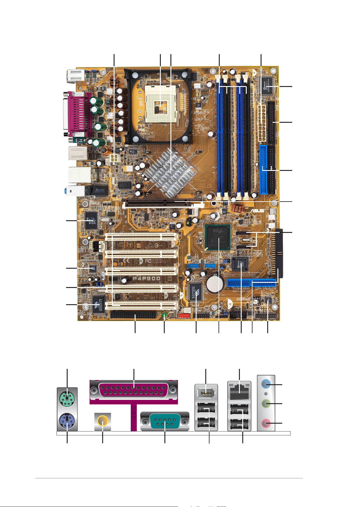
1.4.1 Major components
The following are the major components of the P4P800 Deluxe
motherboard as pointed out in the picture on page 1-7.
1. ATX 12V connector
2. CPU socket
3. North Bridge controller
4. DDR DIMM sockets
5. ATX Power connector
6. Super I/O controller
7. Floppy disk connector
8. IDE connectors
9. AGP slot
10. Serial A T A connectors
11. Speech Controller
12. RAID Ultra ATA/133 connector
13. Flash ROM
14. South Bridge controller
15. ATA133 RAID controller
16. Standby Power LED
18. 1394 controller
19. PCI slots
20. Audio CODEC
21. Gigabit LAN controller
22. PS/2 Mouse
23 Parallel port
24. IEEE 1394 port
25. RJ-45 port
26. Line In jack
27. Line Out jack
28. Microphone jack
29. USB 2.0 ports 3 and 4
30. USB 2.0 ports 1 and 2
31. Serial port
32. S/PDIF output port
33. Keyboard port
17. WiFi slot
See page 1-8 for the specifications of each component. Refer to
Chapter 2 for detailed information on the components.
ASUS P4P800 Deluxe motherboard user guide
1-7
43
2
5
1
0
6
22
6
7
8
23 25
24
7
8
9
21
20
19
18
1
17
16
1415
13
12
11
2
2
1-8
33
3132
2
30
29
Chapter 1: Product introduction

1.4.2 Core specifications
1
ATX 12V connector . This power connector connects the 4-pin 12V
plug from the ATX 12V power supply .
2
CPU socket. A 478-pin surface mount, Zero Insertion Force (ZIF)
socket for the Intel
®
Pentium® 4 Processor (and Intel’s future Prescott
CPU) support with 800/533/400 MHz system bus that allows up to
6.4GB/s data transfer rates.
3
North bridge controller . The Intel
®
82865PE Memory Controller Hub
(MCH) provides the processor interface with 800/533/400 MHz
frequency, system memory interface at 400/333/266MHz operation,
and 1.5V AGP interface that supports AGP 3.0 specification including
8X Fast Write protocol.
4
DDR DIMM sockets. These four 184-pin DIMM sockets support up to
4GB system memory using unbuffered non-ECC PC3200/2700/2100
DDR DIMMs.
5
ATX power connector . This 20-pin connector connects to an ATX
+12V power supply. The power supply must have at least 1A on the
+5V standby lead (+5VSB).
6
7
8
9
10
Super I/O controller . The Winbond 83627THF Low Pin Count (LPC)
interface provides the commonly used Super I/O functionality. The
chipset supports a high-performance floppy disk controller for a 360K/
720K/1.44M/2.88M floppy disk drive, a multi-mode parallel port, two
serial ports, a GAME port, the mouse and keyboard interface and
the LPC (Low Pin Count) interface.
Floppy disk connector . This connector accommodates the provided
ribbon cable for the floppy disk drive. One side of the connector is
slotted to prevent incorrect insertion of the floppy disk cable.
IDE connectors. These dual-channel bus master IDE connectors
support Ultra DMA100/66, PIO Modes 3 & 4 IDE devices. Both the
primary (blue) and secondary (black) connectors are slotted to prevent
incorrect insertion of the IDE ribbon cable.
AGP slot. This Accelerated Graphics Port (AGP) slot supports 1.5V
AGP8X mode graphics cards for 3D graphical applications.
Serial A T A connectors. These two 7-pin connectors accommodate
the thin cables for Serial AT A devices.
11
Speech Controller. The Winbond 83791S + W55F10 facilitates the
POST speech functionality.
ASUS P4P800 Deluxe motherboard user guide
1-9

12
RAID connector . These dual-channel bus master IDE connectors
support Ultra DMA/133 IDE devices. These connectors are slotted to
prevent incorrect insertion of the IDE ribbon cable.
13
14
15
16
17
Flash ROM. This 4Mb firmware contains the programmable BIOS
program.
South bridge controller . T he Intel
®
ICH5R is a subsystem that
integrates various I/O functions including 2-channel AT A100 bus
master IDE controller , SA TA RAID controller, up to eight USB 2.0/1.1
ports, I/O APIC, AC’97 2.2 interface, and PCI 2.3 interface.
ATA133 RAID controller . The VIA
®
VT6410 IDE RAID controller
provides high performance RAID 0, RAID 1, RAID 0+1 and JBOD
RAID methods.
Standby power LED. This LED lights up if there is a standby power
on the motherboard. This LED acts as a reminder to turn off the
system power before plugging or unplugging devices.
Wi-Fi slot. The Wi-Fi (Wireless Fidelity) slot connects a wireless
networking module that allows 11Mbps transmission (with a
fallback to 5.5, 2, and 1 Mbps) in the 2.4 GHz band. Wi-Fi networks
use radio technologies known as IEEE 802.11b to provide a fast
reliable wireless connectivity.
18
19
20
21
22
IEEE 1394 controller. The VIA
®
6307 controller supports IEEE 1394
functionality with maximum data transfer rates of 400 Mbps.
PCI slots. These five 32-bit PCI 2.3 expansion slots support bus
master PCI cards like SCSI or LAN cards with 133MB/s maximum
throughput.
Audio CODEC. The ADI AD1985 is an AC’97 CODEC that allows
6-channel audio playback. The audio CODEC provides six DAC
channels for 5.1 surround sound, S/PDIF output, AUX and Line In
stereo inputs, integrated headphone amplifier, greater than 90dB
dynamic range with the jack sense and jack enumeration feature.
LAN controller . The 3Com
®
3C940 Gigabit Ethernet is a single-chip
solution for LAN on Motherboard (LOM) application. The 3C940
provides a 32-bit interface and supports 1000/100/10 Mbps data
transfer rates.
PS/2 mouse port. This green 6-pin connector is for a PS/2 mouse.
1-10
Chapter 1: Product introduction

23
Parallel port. This 25-pin port connects a parallel printer, a scanner ,
or other devices.
24
25
26
27
28
29
IEEE1394 port. This 6-pin IEEE 1394 port provides high-speed
connectivity for audio/video devices, storage peripherals, other
PCs and/or portable devices.
RJ-45 port. This port allows connection to a Local Area Network
(LAN) through a network hub.
Line In jack. This Line In (light blue) jack connects a tape player or
other audio sources. In 6-channel mode, the function of this jack
becomes Rear Speaker Out.
Line Out jack. This Line Out (lime) jack connects a headphone or a
speaker. In 6-channel mode, the function of this jack becomes Front
Speaker Out.
Microphone jack. This Mic (pink) jack connects a microphone. In 6channel mode, the function of this jack becomes Bass/Center
Speaker Out.
USB 2.0 ports 3 and 4. These two 4-pin Universal Serial Bus
(USB) ports are available for connecting USB 2.0 devices.
30
31
32
33
USB 2.0 ports 1 and 2. These two 4-pin Universal Serial Bus (USB)
ports are available for connecting USB 2.0 devices.
Serial port. This 9-pin COM1 port is for pointing devices or other
serial devices.
S/PDIF jack. This jack connects to external audio output devices.
PS/2 keyboard port. This purple connector is for a PS/2 keyboard.
ASUS P4P800 Deluxe motherboard user guide
1-11

1-12
Chapter 1: Product introduction

Chapter 2
This chapter describes the hardware setup
procedures that you have to perform when
installing system components. It includes
details on the switches, jumpers, and
connectors on the motherboard.
Hardware information

Chapter summary
2.1 Motherboard installation ............................... 2-1
2.2 Motherboard layout ....................................... 2-2
2.3 Before you proceed ....................................... 2-3
2.4 Central Processing Unit (CPU) ..................... 2-4
2.5 System memory ........................................... 2-10
2.6 Expansion slots ........................................... 2-15
2.7 Jumpers ........................................................ 2-20
2.8 Connectors ................................................... 2-23
ASUS P4P800 Deluxe motherboard
2.1 Motherboard installation
Before you install the motherboard, study the configuration of your chassis
to ensure that the motherboard fits into it. The P4P800 Deluxe uses the
ATX form factor that measures 12 inches x 9.6 inches.
Make sure to unplug the power cord before installing or removing the
motherboard. Failure to do so may cause you physical injury and
damage motherboard components.
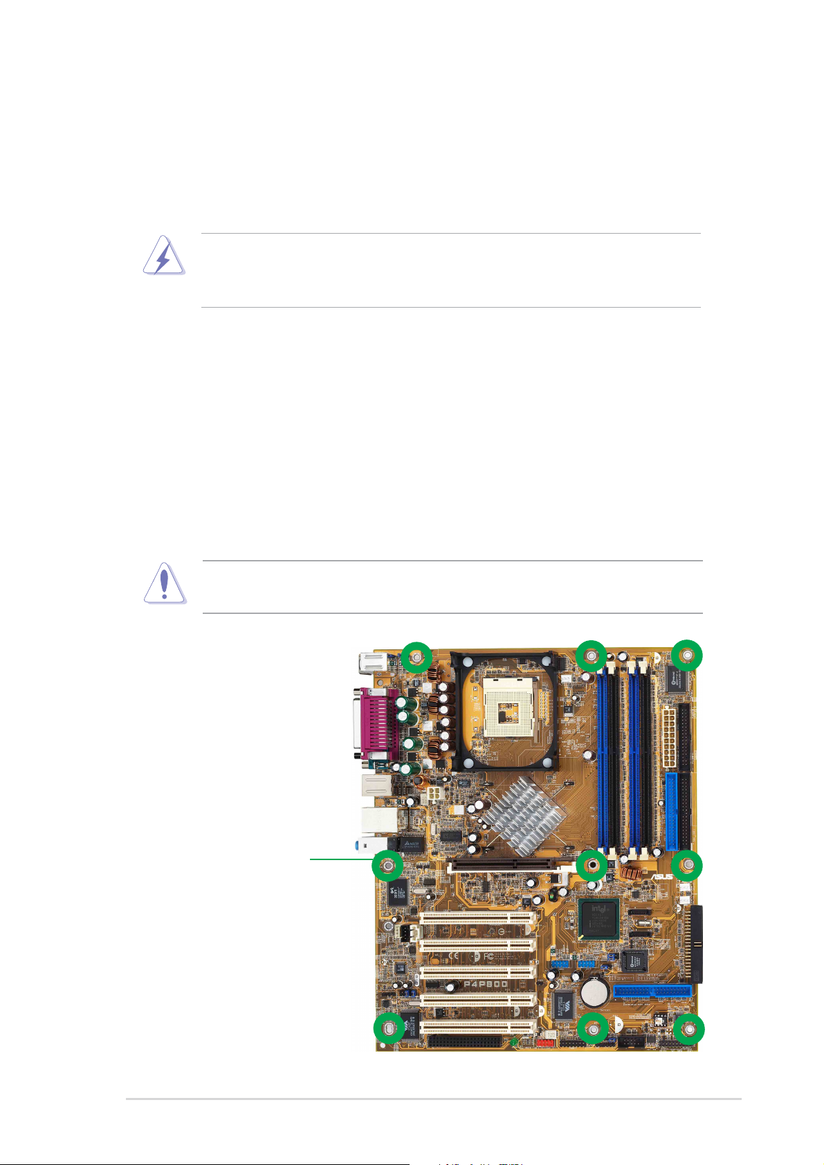
2.1.1 Placement direction
When installing the motherboard, make sure that you place it into the
chassis in the correct orientation. The edge with external ports goes to the
rear part of the chassis as indicated in the image below.
2.1.2 Screw holes
Place nine (9) screws into the holes indicated by circles to secure the
motherboard to the chassis.
Do not overtighten the screws! Doing so may damage the
motherboard.
Place this side towards
the rear of the chassis
ASUS P4P800 Deluxe motherboard user guide
2-1
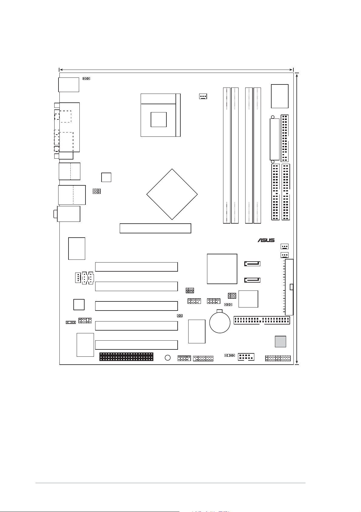
2.2 Motherboard layout
®
24.5cm (9.6in)
PS/2KBMS
T: Mouse
B: Keyboard
SPDIF_O
COM1
Bottom:
Top:
USB1
1394
USB2
USB2.0
Top:
T: USB4
RJ-45
B: USB3
Top:Line In
Center:Line Out
Below:Mic In
3Com
MODEM1
Codec
SPDIF_OUT
KBPWR
PARALLEL PORT
Gbit
3C940
CD1
Audio
FP_AUDIO
VIA
ATX12V1
USBPW12
USBPW34
AUX1
Chipset
VT6307
Socket 478
Accelerated Graphics Port (AGP1)
PCI1
PCI2
PCI3
P4P800
PCI4
PCI5
Intel
82865PE
Memory
Controller
Hub
WIFI
SB_PWR1
USB_56 USB_78
TRPWR1
IE1394_2
CPU_FAN
USBPW56
USBPW78
VIA
Chipset
VT6410
GAME1
DDR DIMM_A2 (64 bit,184-pin module)
DDR DIMM_A1 (64 bit,184-pin module)
DDR DIMM_B2 (64 bit,184-pin module)
DDR DIMM_B1 (64 bit,184-pin module)
CHA_FAN1
PWR_FAN1
SATA1
Intel
ICH5R
CLRTC1
CR2032 3V
Lithium Cell
CMOS Power
CHASSIS1
SMB20
SATA2
4Mbit
Firmware
Hub
PRI_RAID1
COM2
I/O
Super
ATX Power Connector
FLOPPY1
PRI_IDE1
SEC_IDE1
30.5cm (12.0in)
SEC_RAID1
Speech
Controller
PANEL1
2-2
Chapter 2: Hardware information
 Loading...