

ASUS M4A78-AM User Manual

M4A78-AM
Motherboard

E4614
First Edition V1
May 2009
Copyright © 2009 ASUSTeK Computer Inc. All Rights Reserved.
No part of this manual, including the products and software described in it, may be reproduced,
transmitted, transcribed, stored in a retrieval system, or translated into any language in any form or by any
means, except documentation kept by the purchaser for backup purposes, without the express written
permission of ASUSTeK Computer Inc. (“ASUS”).
Product warranty or service will not be extended if: (1) the product is repaired, modied or altered, unless
such repair, modication of alteration is authorized in writing by ASUS; or (2) the serial number of the
product is defaced or missing.
ASUS PROVIDES THIS MANUAL “AS IS” WITHOUT WARRANTY OF ANY KIND, EITHER EXPRESS
OR IMPLIED, INCLUDING BUT NOT LIMITED TO THE IMPLIED WARRANTIES OR CONDITIONS OF
MERCHANTABILITY OR FITNESS FOR A PARTICULAR PURPOSE. IN NO EVENT SHALL ASUS, ITS
DIRECTORS, OFFICERS, EMPLOYEES OR AGENTS BE LIABLE FOR ANY INDIRECT, SPECIAL,
INCIDENTAL, OR CONSEQUENTIAL DAMAGES (INCLUDING DAMAGES FOR LOSS OF PROFITS,
LOSS OF BUSINESS, LOSS OF USE OR DATA, INTERRUPTION OF BUSINESS AND THE LIKE),
EVEN IF ASUS HAS BEEN ADVISED OF THE POSSIBILITY OF SUCH DAMAGES ARISING FROM ANY
DEFECT OR ERROR IN THIS MANUAL OR PRODUCT.
SPECIFICATIONS AND INFORMATION CONTAINED IN THIS MANUAL ARE FURNISHED FOR
INFORMATIONAL USE ONLY, AND ARE SUBJECT TO CHANGE AT ANY TIME WITHOUT NOTICE,
AND SHOULD NOT BE CONSTRUED AS A COMMITMENT BY ASUS. ASUS ASSUMES NO
RESPONSIBILITY OR LIABILITY FOR ANY ERRORS OR INACCURACIES THAT MAY APPEAR IN THIS
MANUAL, INCLUDING THE PRODUCTS AND SOFTWARE DESCRIBED IN IT.
Products and corporate names appearing in this manual may or may not be registered trademarks or
copyrights of their respective companies, and are used only for identication or explanation and to the
owners’ benet, without intent to infringe.
ii

Contents
Notices ......................................................................................................... vi
Safety information ..................................................................................... vii
About this guide ........................................................................................ vii
M4A78-AM specications summary ......................................................... ix
Chapter 1 Product introduction
1.1 Welcome! ...................................................................................... 1-1
1.2 Package contents .........................................................................
1.3 Special features ............................................................................
1.3.1 Product highlights ...........................................................
1.3.2 Innovative ASUS features ...............................................
1.4 Before you proceed .....................................................................
1.5 Motherboard overview .................................................................
1.5.1 Placement direction ........................................................
1.5.2 Screw holes ....................................................................
1.5.3 Motherboard layout .........................................................
1.5.4 Layout contents ...............................................................
1.6 Central Processing Unit (CPU) ...................................................
1.6.1 Installing the CPU ...........................................................
1.6.2 Installing the heatsink and fan ......................................
1.7 System memory .........................................................................
1.7.1 Overview ........................................................................
1.7.2 Memory congurations ..................................................
1.7.3 Installing a DIMM ..........................................................
1.7.4 Removing a DIMM ........................................................
1.8 Expansion slots ..........................................................................
1.8.1 Installing an expansion card .........................................
1.8.2 Conguring an expansion card .....................................
1.8.3 PCI slots ........................................................................
1.8.4 PCI Express x1 slot .......................................................
1.8.5 PCI Express x16 slot .....................................................
1.9 Jumpers ......................................................................................
1.10 Connectors .................................................................................
1-1
1-1
1-1
1-3
1-5
1-6
1-6
1-6
1-7
1-7
1-8
1-8
1-10
1-11
1-11
1-12
1-17
1-17
1-18
1-18
1-18
1-18
1-18
1-18
1-19
1-21
iii

Contents
1.10.1 Rear panel connectors .................................................. 1-21
1.10.2 Internal connectors .......................................................
1.11 Software support ........................................................................
1.11.1 Installing an operating system ......................................
1.11.2 Support DVD information ..............................................
Chapter 2 BIOS information
2.1 Managing and updating your BIOS ............................................ 2-1
2.1.1 ASUS Update utility ........................................................
2.1.2 ASUS EZ Flash 2 utility ...................................................
2.1.3 ASUS CrashFree BIOS 3 utility ......................................
2.2 BIOS setup program ....................................................................
2.2.1 BIOS menu screen ..........................................................
2.2.2 Menu bar .........................................................................
2.2.3 Navigation keys ...............................................................
2.2.4 Menu items .....................................................................
2.2.5 Submenu items ...............................................................
2.2.6 Conguration elds .........................................................
2.2.7 General help ...................................................................
2.2.8 Pop-up window ...............................................................
2.2.9 Scroll bar .........................................................................
2.3 Main menu ....................................................................................
2.3.1 System Time ...................................................................
2.3.2 System Date ...................................................................
2.3.3 Primary IDE Master/Slave ...............................................
2.3.4 SATA 1~4 ........................................................................
2.3.5 SATA Conguration .........................................................
2.3.6 System Information .........................................................
2.4 Advanced menu ...........................................................................
2.4.1 JumperFree Conguration ............................................
2.4.2 CPU Conguration ........................................................
2.4.3 Chipset ..........................................................................
2.4.4 Onboard Devices Conguration ....................................
1-23
1-31
1-31
1-31
2-1
2-2
2-3
2-4
2-5
2-5
2-6
2-6
2-6
2-6
2-6
2-6
2-6
2-7
2-7
2-7
2-7
2-8
2-9
2-9
2-9
2-10
2-12
2-13
2-14
iv

Contents
2.4.5 PCI PnP ........................................................................ 2-14
2.4.6 USB Conguration ........................................................
2.5 Power menu ................................................................................
2.5.1 Suspend Mode ..............................................................
2.5.2 ACPI 2.0 Support ..........................................................
2.5.3 ACPI APIC Support .......................................................
2.5.4 APM Conguration ........................................................
2.5.5 HW Monitor Conguration .............................................
2.6 Boot menu ..................................................................................
2.6.1 Boot Device Priority ......................................................
2.6.2 Boot Settings Conguration ..........................................
2.6.3 Security .........................................................................
2.7 Tools menu .................................................................................
2.7.1 ASUS EZ Flash 2 ..........................................................
2.7.2 AI NET 2
2.8 Exit menu ....................................................................................
........................................................................ 2-20
2-15
2-16
2-16
2-16
2-16
2-16
2-17
2-18
2-18
2-18
2-19
2-20
2-20
2-21
v
Notices
Federal Communications Commission Statement
This device complies with Part 15 of the FCC Rules. Operation is subject to the following two
conditions:
• This device may not cause harmful interference, and
• This device must accept any interference received including interference that may cause
undesired operation.
This equipment has been tested and found to comply with the limits for a Class B digital
device, pursuant to Part 15 of the FCC Rules. These limits are designed to provide
reasonable protection against harmful interference in a residential installation. This
equipment generates, uses and can radiate radio frequency energy and, if not installed
and used in accordance with manufacturer’s instructions, may cause harmful interference
to radio communications. However, there is no guarantee that interference will not occur
in a particular installation. If this equipment does cause harmful interference to radio or
television reception, which can be determined by turning the equipment off and on, the user
is encouraged to try to correct the interference by one or more of the following measures:
•
Reorient or relocate the receiving antenna.
•
Increase the separation between the equipment and receiver.
•
Connect the equipment to an outlet on a circuit different from that to which the receiver is
connected.
•
Consult the dealer or an experienced radio/TV technician for help.
The use of shielded cables for connection of the monitor to the graphics card is required
to assure compliance with FCC regulations. Changes or modications to this unit not
expressly approved by the party responsible for compliance could void the user’s authority
to operate this equipment.
Canadian Department of Communications Statement
This digital apparatus does not exceed the Class B limits for radio noise emissions from
digital apparatus set out in the Radio Interference Regulations of the Canadian Department
of Communications.
This class B digital apparatus complies with Canadian ICES-003.
REACH
Complying with the REACH (Registration, Evaluation, Authorisation, and Restriction of
Chemicals) regulatory framework, we published the chemical substances in our products at
ASUS REACH website at http://green.asus.com/english/REACH.htm.
DO NOT throw the motherboard in municipal waste. This product has been designed to
enable proper reuse of parts and recycling. This symbol of the crossed out wheeled bin
indicates that the product (electrical and electronic equipment) should not be placed in
municipal waste. Check local regulations for disposal of electronic products.
DO NOT throw the mercury-containing button cell battery in municipal waste. This symbol
of the crossed out wheeled bin indicates that the battery should not be placed in municipal
waste.
vi

Safety information
Electrical safety
•
To prevent electrical shock hazard, disconnect the power cable from the electrical outlet
before relocating the system.
•
When adding or removing devices to or from the system, ensure that the power cables
for the devices are unplugged before the signal cables are connected. If possible,
disconnect all power cables from the existing system before you add a device.
•
Before connecting or removing signal cables from the motherboard, ensure that all
power cables are unplugged.
•
Seek professional assistance before using an adapter or extension cord. These devices
could interrupt the grounding circuit.
•
Ensure that your power supply is set to the correct voltage in your area. If you are not
sure about the voltage of the electrical outlet you are using, contact your local power
company.
•
If the power supply is broken, do not try to x it by yourself. Contact a qualied service
technician or your retailer.
Operation safety
•
Before installing the motherboard and adding devices on it, carefully read all the manuals
that came with the package.
•
Before using the product, ensure that all cables are correctly connected and the power
cables are not damaged. If you detect any damage, contact your dealer immediately.
•
To avoid short circuits, keep paper clips, screws, and staples away from connectors,
slots, sockets and circuitry.
•
Avoid dust, humidity, and temperature extremes. Do not place the product in any area
where it may become wet.
•
Place the product on a stable surface.
•
If you encounter technical problems with the product, contact a qualied service
technician or your retailer.
About this guide
This user guide contains the information you need when installing and conguring the
motherboard.
How this guide is organized
This guide contains the following parts:
•
Chapter 1: Product introduction
This chapter describes the features of the motherboard and the new technology it
supports.
• Chapter 2: BIOS information
This chapter tells how to change system settings through the BIOS Setup menus.
Detailed descriptions of the BIOS parameters are also provided.
vii

Conventions used in this guide
To ensure that you perform certain tasks properly, take note of the following symbols used
throughout this manual.
DANGER/WARNING: Information to prevent injury to yourself
when trying to complete a task.
CAUTION: Information to prevent damage to the components
when trying to complete a task.
IMPORTANT: Instructions that you MUST follow to complete a
task.
NOTE: Tips and additional information to help you complete a
task.
Where to nd more information
Refer to the following sources for additional information and for product and software
updates.
1. ASUS websites
The ASUS website provides updated information on ASUS hardware and software
products. Refer to the ASUS contact information.
2. Optional documentation
Your product package may include optional documentation, such as warranty yers,
that may have been added by your dealer. These documents are not part of the
standard package.
Typography
Bold text Indicates a menu or an item to select.
Italics
Used to emphasize a word or a phrase.
<Key> Keys enclosed in the less-than and greater-than sign means
that you must press the enclosed key.
Example: <Enter> means that you must press the Enter or
Return key.
<Key1>+<Key2>+<Key3> If you must press two or more keys simultaneously, the key
names are linked with a plus sign (+).
Example: <Ctrl>+<Alt>+<D>
viii

M4A78-AM specications summary
CPU Phenom™ X4 / Phenom™ X3 / Athlon™ X2 / Athlon™ /
Chipset AMD 780 / SB710
System bus Up to 5200 MT/s; HyperTransport™ 3.0 interface for AM3 /
Memory Dual-channel memory architecture
Expansion slots 1 x PCI Express™ 2.0 x16 slot
Storage 1 x UltraDMA 133/100 connector
Graphics ATI Radeon HD3200
LAN Realtek 8112 PCIe Gb LAN
Audio VT1708S High Denition Audio 6-channel CODEC
ASUS
overclocking
fetures
Sempron™ processors (socket AM2+ / AM2)
Compatible with Phenom™ II / Athlon™ X4 / Athlon™ X3
/ Athlon™ X2 (AM3 CPU)
Support 45nm CPU
AMD Cool ‘n’ Quiet™ Technology
Support CPU up to 95W
* Refer to www.asus.com for the AMD CPU support list
AM2+ CPU
2000 / 1600 MT/s for AM2 CPU
2 x 240-pin DIMM slots support maximum 8GB unbuffered
ECC and non-ECC DDR2 1200(O.C.)/1066*/800/667MHz
memory modules
* DDR2 1066/1200(O.C.) is supported by AM2+ / AM3 CPU only.
** Refer to www.asus.com for the latest Memory QVL
(Qualied Vendors List).
*** When you install a total memory of 4GB capacity or more,
Windows® 32-bit operating system may only recognize less
than 3GB. We recommend a maximum of 3GB system memory
if you are using a Windows 32-bit operating system.
1 x PCI Express™ x1 slot
2 x PCI slots
Supports PCI Express™ 2.0/1.0 Architecture
4 x Serial ATA 3Gb/s connectors support RAID 0, RAID 1, and
RAID 0+1, JBOD congurations (* For Windows® Vista only)
Maximum shared memory of 256 MB
Supports RGB with max. resolution 2048 x 1536 x 32 Bpp x 75 Hz
* To playback the HD-DVD and Blu-ray Disc, we recommend
system conguration: Graphic shared memory 256MB/Dual-
Core CPU minimum/maximum 1GB memory of Dual-channel
DDR2 667 or Single-channel DDR2 800.
- Supports Jack-detect and Multistreaming technology
- Supports S/PDIF out interface
SFS (Stepless Frequency Selection) from 200MHz to 550MHz
at 1 MHz increment
ASUS C.P.R. (CPU Parameter Recall)
(continued on the next page)
ix

M4A78-AM specications summary
ASUS special features ASUS Q-Fan
USB Supports up to 10 USB 2.0/1.1 ports (6 port at mid-board,
Back panel I/O ports 1 x PS/2 Mouse port
Internal I/O connectors 3 x USB 2.0/1.1 connectors support additional
BIOS 8Mb Flash ROM, AMI BIOS, PnP, DMI v2.0, WfM2.0,
Accessories 1 x Serial ATA cable
Form Factor microATX form factor: 9.6’’ x 8.2’’ (24.4cm x 20.8cm)
Support DVD Drivers
ASUS CrashFree BIOS3
ASUS EZ Flash2
ASUS AI NET 2
ASUS EPU-4 Engine
ASUS MyLogo2
ASUS Turbo Key
4 ports at back panel)
1 x Keyboard/Mouse port
1 x RJ45 port
1 x LPT port
4 x USB 2.0/1.1 ports
6-channel Audio ports
1 x COM port
1 x VGA port
6 USB 2.0/1.1 ports
1 x IDE connector
1 x SPEAKER connector
4 x SATA connectors
1 x High Denition Front panel audio connector
1 x system panel connector
1 x CD audio-in connector
1 x S/PDIF Out connector
1x CPU/Chassis Fan connector
24-pin ATX power connector
4-pin ATX 12V power connector
ACPI2.0a, SM BIOS v2.5
1 x UltraDMA 133/100/66 cable
1x I/O Shield
User manual
ASUS LiveUpdate Utility
ASUS PC Probe II
Anti-Virus software (OEM version)
AMD OverDrive Utility (AOD)
*Specications are subject to change without notice.
x

Chapter 1
Product introduction
1.1 Welcome!
Thank you for buying an ASUS® M4A78-AM motherboard!
The motherboard delivers a host of new features and latest technologies, making it another
standout in the long line of ASUS quality motherboards!
Before you start installing the motherboard, and hardware devices on it, check the items in
your package with the list below.
1.2 Package contents
Check your motherboard package for the following items.
Motherboard ASUS M4A78-AM motherboard
Cables 1 x Serial ATA cable
1 x Ultra DMA 133/100/66 cable
Accessories 1 x I/O shield
Application DVD ASUS motherboard support DVD
Documentations User manual
If any of the above items is damaged or missing, contact your retailer.
1.3 Special features
1.3.1 Product highlights
AMD® Phenom™ II / Athlon™ X4 / Athlon™ X3 / Athlon™ X2
Chapter 1: Product introduction 1-1
(AM3 CPU)
This motherboard supports AMD® Socket AM3 multi-core processors
with unique L3 cache and delivers better overclocking capabilities
with less power consumption. It features dual-channel DDR2 1066
memory support and accelerates data transfer rate up to 5200MT/s via
HyperTransport™ 3.0 based system bus. This motherboard also supports
AMD® CPUs in the new 45nm manufacturing process.
AMD® Phenom™ X4 / Phenom™ X3 / Athlon™ X2 / Athlon™ /
Sempron™ processors (socket AM2+/AM2)
This motherboard supports AMD® Socket AM2+ multi-core processors.
It features dual-channel DDR2 1066 memory support, data transfer rate
up to 5200MT/s via HyperTransport™ 3.0 based system bus, and AMD®
Cool ‘n’ Quiet™ Technology.
AMD® 780G chipset
The AMD 780G Northbridge is the latest AMD chipset designed for both
HT1.0 and 5200MT/s HyperTransport™ 3.0 (HT 3.0) interface speed and
external graphics in PCI Express 2.0 standard. It features the integrated
ATI RV610-based graphics and supports Directx 10.0.
AMD Cool ‘n’ Quiet Technology
The motherboard supports the AMD Cool ‘n’ Quiet Technology, which
monitors system operation and automatically adjusts CPU voltage and
frequency for a cool and quiet operating environment.
Hybrid CrossFireX™ Support
Boosted Performance with onboard GPU and discrete graphics card.
ATI Hybrid CrossFireX™ technology is a unique hybrid multi-GPU
technology. It takes your gaming experience to the next level boosting PC
performance by enabling the chipset’s integrated graphics.
DDR2 1200 (O.C. ) support
This motherboard supports DDR2 1200 (O.C.). It provides faster data
transfer rate and more bandwidth to increase memory data transfer rate
and computing efciency, enhancing system performance in 3D graphics
and other memory demanding applications.
Ensure that you download the latest BIOS version at www.asus.com and purchase the
memory modules on the ASUS Ofcial Memory Qualied Vendors Lists (QVL).
PCI Express 2.0 support
This motherboard supports the latest PCIe 2.0 devices for double speed
and bandwidth which enhances system performance.
HyperTransport
1-2 ASUS M4A78-AM
HyperTransportTM 3.0 technology provides 2.6 times more bandwith than
HyperTransportTM 1.0, radically improving system efciency to create a
smoother, faster computing environment.
TM
3.0 support
Gigabit LAN solution
The onboard LAN controller is a highly integrated Gb LAN controller. It is
enhanced with an ACPI management function to provide efcient power
management for advanced operating systems.
Serial ATA 3Gb/s technology
The motherboard supports next-generation SATA hard drives based
on the new SATA 3Gb/s storage specication. The onboard SB710
southbridge allows RAID 0, RAID 1, RAID 0+1 and JBOD (for Windows
Vista only) congurations for Serial ATA drives.
1.3.2 Innovative ASUS features
ASUS EPU
The ASUS EPU (Energy Processing Unit) provides total system
power management by detecting current PC loadings and intelligently
moderating power in real-time. It automatically provides the most
appropriate power usage to save power and money!
Turbo Key
ASUS Turbo Key allows you to turn the PC power button into
an overclocking button. After the easy setup, Turbo Key boosts
performances without interrupting ongoing work or games, simply through
pressing the button.
ASUS MyLogo2™
Turn your favorite photos into 256-color boot logos to personalize your
system.
®
ASUS CrashFree BIOS 3
ASUS CrashFree BIOS 3 is an auto-recovery tool that allows you to
restore a corrupted BIOS le using the bundled support DVD, or USB
disk that contains the BIOS le.
ASUS EZ Flash 2
ASUS EZ Flash 2 is a utility that allows you to update the BIOS without
using an OS-based utility.
ASUS Q-Fan
ASUS Q-Fan technology intelligently adjusts CPU and chassis fan
speeds according to system loading to ensure quiet, cool, and efcient
operation.
Chapter 1: Product introduction 1-3

Green ASUS
This motherboard and its packaging comply with the European Union’s
Restriction on the use of Hazardous Substances (RoHS). This is in line
with the ASUS vision of creating environment-friendly and recyclable
products/packaging to safeguard consumers’ health while minimizing the
impact on the environment.
C.P.R. (CPU Parameter Recall)
The BIOS C.P.R. feature automatically restores the CPU default settings
when the system hangs due to overclocking failure. C.P.R. eliminates the
need to open the system chassis and clear the RTC data. Simply shut
down and reboot the system, and the BIOS automatically restores the
CPU parameters to their default settings.
1-4 ASUS M4A78-AM
1.4 Before you proceed
Take note of the following precautions before you install motherboard components or change
any motherboard settings.
• Unplug the power cord from the wall socket before touching any component.
• Before handling components, use a grounded wrist strap or touch a safely grounded
object or a metal object, such as the power supply case, to avoid damaging them due to
static electricity.
• Hold components by the edges to avoid touching the ICs on them.
• Whenever you uninstall any component, place it on a grounded antistatic pad or in the
bag that came with the component.
• Before you install or remove any component, switch off the ATX power supply and
detach its power cord. Failure to do so may cause severe damage to the motherboard,
peripherals, or components.
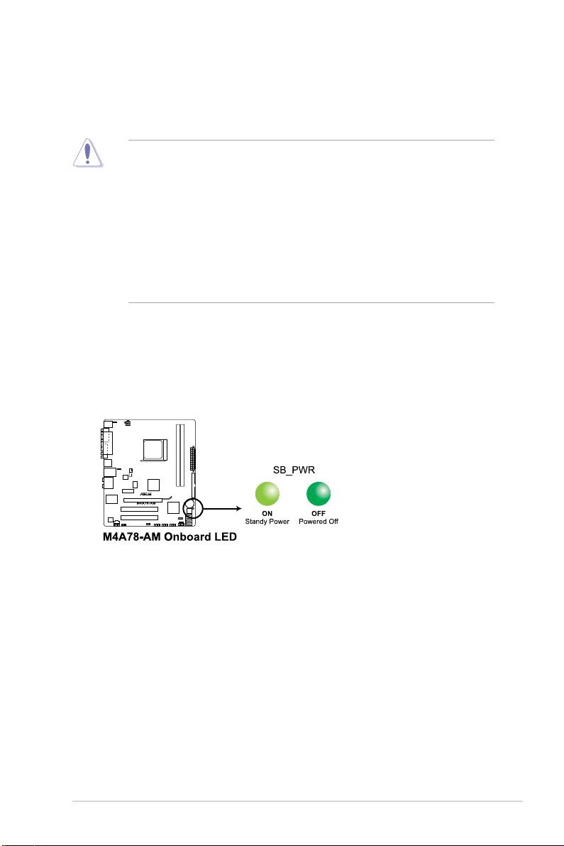
Onboard LED
The motherboard comes with a standby power LED that lights up to indicate that the system
is ON, in sleep mode, or in soft-off mode. This is a reminder that you should shut down
the system and unplug the power cable before removing or plugging in any motherboard
component. The illustration below shows the location of the onboard LED.
Chapter 1: Product introduction 1-5

1.5 Motherboard overview
1.5.1 Placement direction
When installing the motherboard, ensure that you place it into the chassis in the correct
orientation. The edge with external ports goes to the rear part of the chassis as indicated in
the image below.
1.5.2 Screw holes
Place six screws into the holes indicated by circles to secure the motherboard to the chassis.
Do not overtighten the screws! Doing so can damage the motherboard.
Place this side towards
the rear of the chassis.
1-6 ASUS M4A78-AM
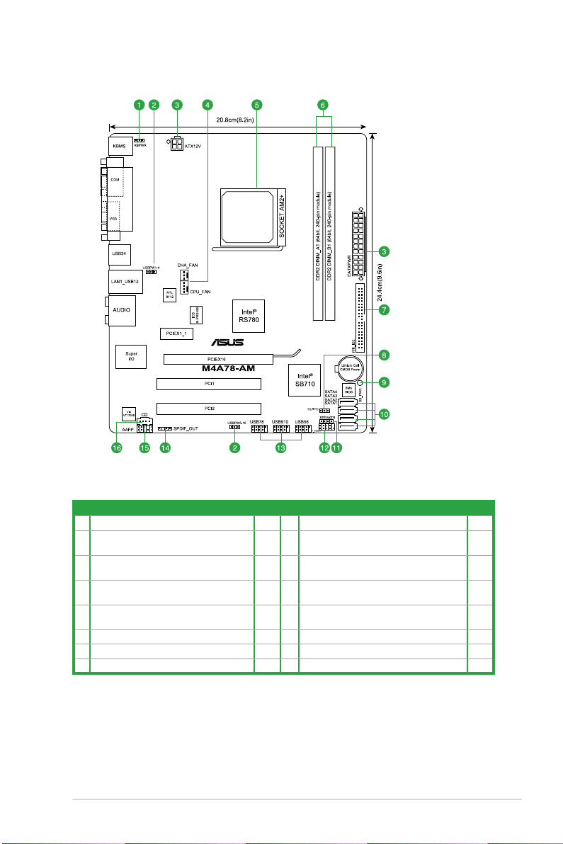
1.5.3 Motherboard layout
1.5.4 Layout contents
Connectors/Jumpers/Slots Page Connectors/Jumpers/Slots Page
1. Keyboard/mouse power (3-pin KBPWR) 1-20 9. Onboard LED 1-5
2. USB device wake-up (3-pin USBPW1-4 and
USBPW5-10)
3. ATX power connectors
(24-pin EATXPWR, 4-pin ATX12V)
4. CPU/Chassis fan connectors
(4-pin CPU_FAN, 3-pin CHA_FAN))
5. AMD CPU socket AM2+ 1-8 13. USB connectors (10-1 pin USB78, USB910,
6. DDR2 DIMM slots 1-11 14. Digital audio connector (4-1 pin SPDIF_OUT) 1-28
7. IDE connector (40-1 pin PRI_EIDE) 1-24 15. Front panel audio connector (10-1 pin AAFP) 1-29
8. Clear RTC RAM (3-pin CLRTC) 1-19 16. Optical drive audio in connector (4-pin CD) 1-27
1-20 10. Serial ATA connectors [red]
1-23 11. Speaker connector (4-pin SPAEKER) 1-29
1-30 12. System panel connector (10-1 pin PANEL) 1-26
(7-pin SATA1-4)
USB56)
1-25
1-27
Chapter 1: Product introduction 1-7
1.6 Central Processing Unit (CPU)
The motherboard comes with a CPU socket designed for AMD® AM3 Phenom™ II / Athon™
X4 / Athon™ X3 / Athlon™ X2 / processors and AM2+ / AM2 Phenom™ X4 / Phenom™ X3 /
Athlon™ X2 / Athlon™ / Sempron™ processors.
The CPU socket is not compatible with AMD® Opteron™ processors. Do not install an
Opteron™ processor on this motherboard.
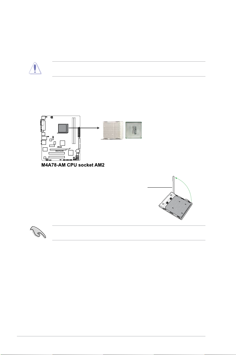
1.6.1 Installing the CPU
To install a CPU:
1. Locate the CPU socket on the motherboard.
2. Press the lever sideways to unlock
the socket, then lift it up to a 90°100° angle.
Socket lever
Ensure that the socket lever is lifted up to 90°-100° angle, otherwise the CPU will not t in
completely.
1-8 ASUS M4A78-AM
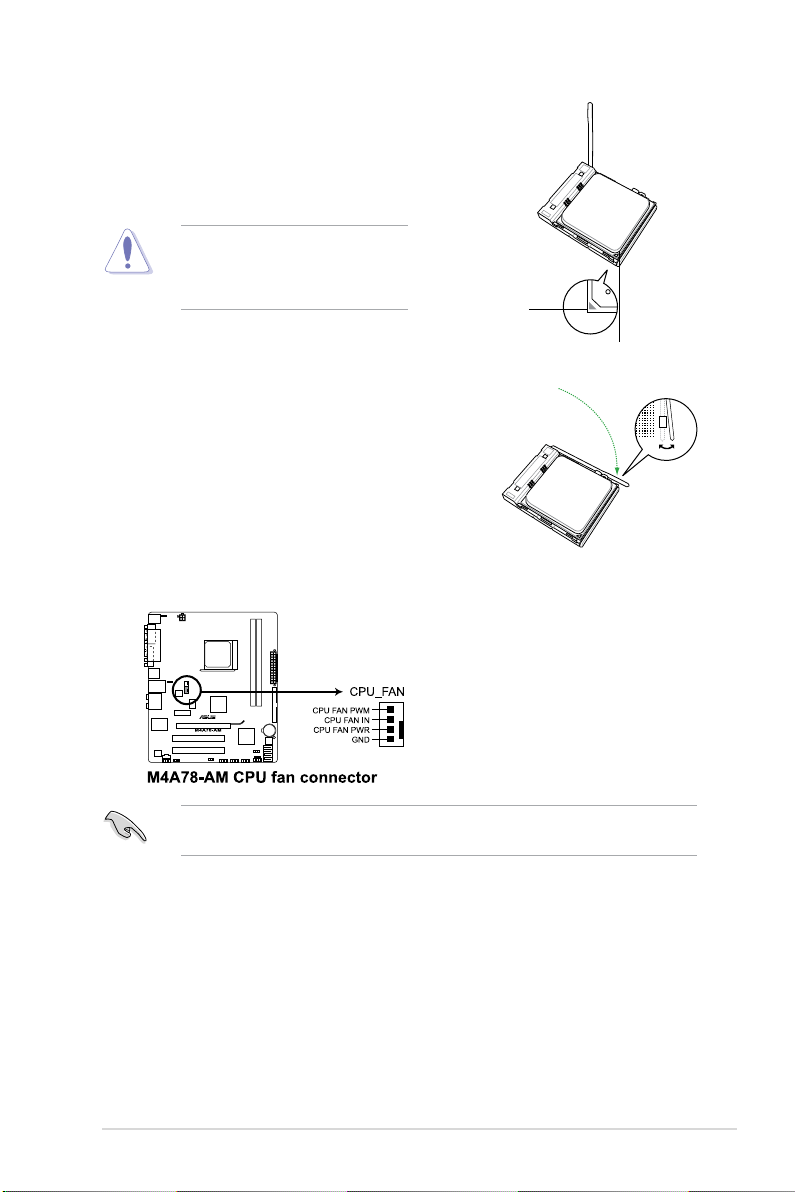
3. Position the CPU above the socket such that the CPU
corner with the gold triangle matches the socket corner
with a small triangle.
4. Carefully insert the CPU into the socket until it ts in place.
The CPU ts only in one correct
orientation. DO NOT force the CPU into
the socket to prevent bending the pins
and damaging the CPU!
Small triangle
Gold triangle
5. When the CPU is in place, push down the socket
lever to secure the CPU. The lever clicks on the side
tab to indicate that it is locked.
6. Install a CPU heatsink and fan following the
instructions that came with the heatsink package.
You can also refer to section 1.6.2 Installing
heatsink and fan for instructions.
7. Connect the CPU fan cable to the CPU_FAN connector on the motherboard.
Do not forget to connect the CPU fan connector! Hardware monitoring errors can occur if
you fail to plug this connector.
Chapter 1: Product introduction 1-9
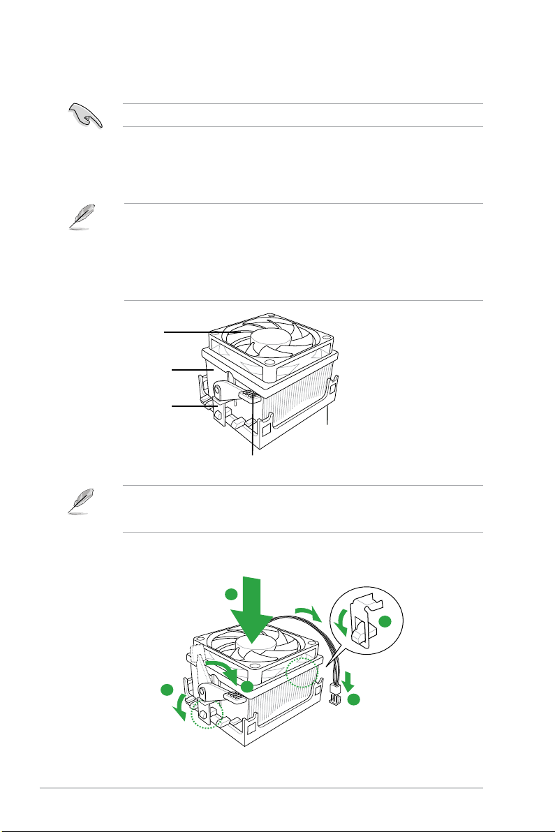
1.6.2 Installing the heatsink and fan
1
3
4
5
2
Ensure that you use only AMD-certied heatsink and fan assembly.
To install the CPU heatsink and fan:
1. Place the heatsink on top of the installed CPU, making sure that the heatsink ts
properly on the retention module base.
• The retention module base is already installed on the motherboard upon purchase.
• You do not have to remove the retention module base when installing the CPU or
installing other motherboard components.
• If you purchased a separate CPU heatsink and fan assembly, ensure that a Thermal
Interface Material is properly applied to the CPU heatsink or CPU before you install the
heatsink and fan assembly.
CPU Fan
CPU Heatsink
Retention bracket
Retention Module Base
Retention bracket lock
Your boxed CPU heatsink and fan assembly should come with installation instructions for
the CPU, heatsink, and the retention mechanism. If the instructions in this section do not
match the CPU documentation, follow the latter.
2. Attach one end of the retention bracket to the retention module base.
1-10 ASUS M4A78-AM
 Loading...