

Page 1

USER’S
GUIDE
Global Array Manager
Transition Tool Client
Software
May 2003
First Edition
®
DB15-000278-00
Page 2

This document contains proprietary information of LSI Logic Cor poration. The
information contained herein is not to be used by or disclosed to third parties
without the express written permission of an officer of LSI Logic Corporation.
Document DB15-000278-00, First Edition (May 2003)
This document describes version 5.20 of LSI Logic Corporation’s Global Array
Management Client software. This document will remain the official reference
source for all revisions/releases of this product until rescinded by an update.
LSI Logic Corporation reser ves the right to make changes to any products herein
at any time without notice. LSI Logic does not assume any responsibility or
liability arising out of the application or use of any product described herein,
except as expressly agreed to in writing by LSI Logic; nor does the purchase or
use of a product from LSI Logic convey a license under any patent rights,
copyrights, trademark rights, or any other of the intellectual property rights of LSI
Logic or third parties.
Copyright © 2001-2003 by LSI Logic Corporation. All rights reserved.
TRADEMARK ACKNOWLEDGMENT
LSI Logic, the LSI Logic logo design, MORE, Mylex, eXtremeRAID, and
SANmapping are trademarks or registered trademarks of LSI Logic Corporation.
All other brand and product names may be trademarks of their respective
companies.
SOFTWARE LICENSE AND WARRANTY POLICY
Limited Warranty
LSI warrants to the original purchaser of the product enclosed herein
(“Customer”) that (a) for a period of three (3) years from the date of Customer’s
purchase of the Product (excluding batteries and memory) (the “Product
Warranty Period”), and (b) for a period of one (1) year from the date of purchase
of the Product by Customer (the “Battery/Memory Warranty Period”), the batteries
and memory included in the Product will (i) be free from defects in workmanship
and materials, and (ii) substantially conform to the documentation or other
specifications for the Product. The limited warranties herein shall not apply to and
shall be void for any Product that has been misused (including static discharge,
improper installation, or accident), abused, modified, damaged as a result of
actions on the part of Customer or its agents or its processes, unauthorized
service or par ts, used in a manner inconsistent with nor mal computer operations
(including but not limited to electrical irregularities, lightning or power line related
damage, or other abnormal occurrences), or to normal wear and tear of the
Product. The warranty herein is made to and for the benefit of the original
purchaser of this Product and is non-transferable.
ii
Version 1.0 Copyright © 2001-2003 by LSI Lo gic Corporation. All rights reser ved.
Page 3

This warranty will not apply to, and LSI provides no warranty for any BIOS,
software, ROM-based firmware or other product developed or manufactured by
any third party whether including with this Product or not. Such warranty or
warranties are provided by third parties and, to the extent permitted thereby, shall
be made available and are hereby assigned by LSI to Customer.
Customer may obtain warranty service during the Product Warranty Period or
Battery/Memor y Warranty Period, as the case may be, if (a) Customer has
contacted LSI at the telephone number listed LSI’s web site at www.lsilogic.com
to obtain a Returned Material Authorization (“RMA”) number and appropriate
instructions from LSI, (b) after obtaining LSI’s authorization, Customer has
returned the Product if so instructed to an authorized LSI service facility or to LSI
in accordance with LSI’s instructions and the terms of this Agreement, shipping
costs to be borne by LSI, and (c) Customer has provided proof of purchase price
and date for unregistered Product. LSI shall bear one-way shipping, packing and
insurance costs and all other costs, excluding labor and parts, necessary to
effectuate repair or replacement under this warranty. All Product repaired or
replaced under this warranty shall be returned to Customer at Customer’s
expense. Repair or replacement Product provided under this limited Product
warranty will be furnished on an exchange basis and may be new or
reconditioned. All Product returned under this warranty shall become the property
of LSI. LSI shall notify Customer in the event that the Product returned under the
warranty does not, in LSI’s sole determination, comply with the conditions and
requirements set forth herein and, unless disposition instructions are given by
Customer for the Product within thirty (30) days of such notification, the Product
shall be returned to Customer freight collect.
Warranty Disclaimer
EXCEPT AS SET FORTH IN THIS DOCUMENT, LSI MAKES NO
WARRANTIES, WHETHER EXPRESS, IMPLIED, OR STATUTORY
REGARDING OR RELATING TO THE PRODUCT, OR ANY MATERIALS OR
SERVICES FURNISHED OR PROVIDED TO OEM UNDER THIS AGREEMENT,
INCLUDING MAINTENANCE AND SUPPORT. LSI SPECIFICALLY DISCLAIMS
ALL IMPLIED WARRANTIES, INCLUDING, WITHOUT LIMITATION, THE
IMPLIED WARRANTIES OF NON-INFRINGEMENT, MERCHANTABILITY AND
FITNESS FOR A PARTICULAR PURPOSE WITH RESPECT TO THE
PRODUCT AND ANY OTHER MATERIALS AND SERVICES, AND WITH
RESPECT TO THE USE OF ANY OF THE FOREGOING.
THE REMEDIES STATED IN THIS DOCUMENT CONSTITUTE CUSTOMER’S
EXCLUSIVE REMEDIES AND LSI’S SOLE LIABILITY FOR BREACH OF THE
LIMITED WARRANTIES SET FORTH HEREIN.
Version 1.0 Copyright © 2001-2003 by LSI Lo gic Corporation. All rights reser ved.
iii
Page 4

Software License
Subject to the terms and conditions of this Agreement, LSI grants Customer a
non-exclusive, worldwide, non-transferable, revocable, royalty-free license to use,
perform and display the LSI software that is a part of the Product (“LSI Software”)
solely as part of the Product incorporated into the OEM Products that and not on
a standalone basis. Customer may not (a) sell, lease, license, or sublicense the
LSI Software, (b) de-compile, disassemble, reverse engineer, or otherwise
attempt to derive source code from the LSI Software, in whole or in part, except
to the extent such restriction is prohibited by applicable law, (c) modify o r create
derivative works from the LSI Software, or (d) use the LSI Software to provide
processing services to third par ties or otherwise use the LSI Software on a
service bureau basis, electronically distribute or timeshare the LSI Software or
market the LSI Software by interactive cable or remote processing services.
Limitation of Liability
IN NO EVENT SHALL LSI’S TOTAL, CUMULATIVE LIABILITY ARISING FROM
THE SALE, USE AND DISPOSITION OF THE PRODUCT AND/OR THE
LICENSING OF THE LSI SOFTWARE EXCEED THE AMOUNT PAID BY
CUSTOMER FOR THIS PRODUCT. IN NO EVENT SHALL LSI BE LIABLE TO
CUSTOMER OR ANY THE OTHER FOR ANY PUNITIVE, INCIDENTAL,
INDIRECT, CONSEQUENTIAL OR SPECIAL DAMAGES, INCLUDING LOSS OF
PROFITS, INCURRED BY THAT PARTY, HOWEVER CAUSED AND UNDER
ANY THEORY OF LIABILITY, WHETHER BASED IN CONTRACT, TORT
(INCLUDING, WITHOUT LIMITATION, NEGLIGENCE OR PR ODUCT LIABILITY)
OR WARRANTY, IN CONNECTION WITH THE SALE, USE AND DISPOSITION
OF THE PRODUCT AND/OR THE LICENSING OF THE LSI SOFTWARE, EVEN
IF ADVISED OF THE POSSIBILITY OF SUCH DAMAGES.
iv
JB
To receive product literature, address your request to:
To receive product literature, visit us at http://www.lsilogic.com.
For a current list of our distributors, sales offices, and design resource
centers, view our web page located at
http://www.lsilogic.com/contacts/index.html
Version 1.0 Copyright © 2001-2003 by LSI Lo gic Corporation. All rights reser ved.
Page 5

Preface
This User’s Guide covers the steps involved to install and use the client
®
component of Mylex’s Global Array Manager
MegaRAID Ultra 320 and Mylex PCI Disk Array Controllers.
For information on installing and r unning the server component of Global
Array Manager Transition Tool, consult the Global Array Manager
Transition Tool Ser ver Software Installation Guide and User Manual
DB15-000279-00.
Transition Tool with
Audience
Organization
This document assumes that you have familiarity with RAID controllers
and related support devices.
The people who benefit from this book are:
• Network administrators who need to install and use Global Array
Manager Transition Tool with MegaRAID or Mylex controllers
• Engineers and managers who are evaluating MegaRAID or Mylex
controllers for possible use in a system
This document has the following chapters and appendixes:
• Chapter 1, Introduction, introduces the Global Array Manager
Transition Tool (GAM TT) Client software, which manages
MegaRAID Ultra320 and Mylex AcceleRAID 160/170/170LP/352 and
eXtremeRAID 2000/3000 PCI RAID controller families.
®
• Chapter 2, Installation, explains how to install and un-install the
GAM TT Client software.
Global Array Manager Client Software User’s Guide v
Version 1.0 Copyright © 2001-2003 by LSI Lo gic Corporation. All rights reser ved.
Page 6

Conventions
• Chapter 3, Startup and Navigation, describes how to start and
navigate through the GAM TT Client.
• Chapter 4, Configuration, describes how to use the RAIDAssist
configuration wizard to configure or re-configure your disk array
system.
• Chapter 5, Monitoring, explains the monitoring functions available to
gather information about the status of your disk array system.
• Chapter 6, Maintenance Processes, describes maintenance
functions available for individual disk arrays and drives.
• Appendix A, Event Information, provides event information about
drive and controller failures.
Throughout the manual, the following conventions are used to describe
user interaction with the product:
Convention Definition
bold Enter the bold text exactly as shown.
↵ Press the Enter key, or
Enter Press the key labeled “Enter” (or “Delete”, etc.)
File->Run Select the Run option from the pull-down menu activated
when the File menu pad is selected.
Note: Notes contain supplementary information that can have an
effect on system performance.
Caution:
Cautions are notifications that a proscribed action has the
potential to adversely affect equipment operation, system
performance, or data integrity.
WARNING:
vi Preface
Version 1.0 Copyright © 2001-2003 by LSI Lo gic Corporation. All rights reser ved.
Warnings are notifications that a proscribed action will
definitely result in equipment damage, data loss, or
personal injury.
Page 7

Chapter 1
Introduction
Contents
1.1 Overview 1-1
1.1.1 Global Array Manager Transition Tool Components 1-1
1.1.2 Configuration Functions 1-2
1.1.3 Monitoring Functions 1-2
1.2 Requirements 1-2
Chapter 2
Installation
2.1 Installation Overview 2-1
2.2 Installation of the Global Array Manager Transition Tool Client 2-1
2.3 Installing Global Array Manager Transition Tool Client with Linux
Chapter 3
Startup and Navigation
1.1.4 Maintenance Functions 1-2
1.2.1 Client Hardware and Software 1-3
2.2.1 Installing GAM TT Client Software 2-1
2-3
2.3.1 Install Wine 2-4
2.3.2 Install GAM TT Client 2-4
2.3.3 To Uninstall GAM TT Client Software 2-4
3.1 Starting Global Array Manager Transition Tool 3-1
3.1.1 Server Component 3-1
3.1.2 Client Component 3-1
3.2 Navigating Global Array Manager Transition Tool Client 3-2
3.2.1 Button Controls 3-2
Global Array Manager Transition Tool Client Software User’s Guide vii
Version 1.0 Copyright © 2001-2003 by LSI Lo gic Corporation. All rights reser ved.
Page 8

3.2.2 Components of the GAM TT Client Opening Screen 3-3
3.2.3 Components of the Controller View Window 3-6
3.3 Status Icons 3-8
3.3.1 Menu Bar and Menus 3-9
3.3.2 Toolbar and Toolbar Icons 3-14
3.4 Exiting Global Array Manager Transition Tool 3-15
3.4.1 Exiting GAM TT Server 3-16
3.5 Setting Up Server Groups and Servers 3-17
3.5.1 Adding a Server Group to the Server Group List 3-17
3.5.2 Adding a Server to the Server Groups List 3-18
3.6 Signing On to a Server 3-19
3.6.1 Security Access Levels 3-19
3.6.2 Signing On 3-20
3.7 Setting and Modifying User Preferences 3-22
3.7.1 Alert Preferences 3-23
Chapter 4
Configuration
3.7.2 Alarm Setup 3-24
3.7.3 Communication 3-32
3.7.4 Event Editor 3-34
3.8 For More Information... 3-36
4.1 Introduction 4-1
4.2 Configuration Lock 4-1
4.3 Setting and Modifying Controller Options 4-2
4.3.1 Controller Options 4-2
4.3.2 Advanced Controller Options 4-5
4.4 Modifying Physical Device Options 4-7
4.5 Running RAID Assist 4-9
4.5.1 Entering RAID Assist 4-9
4.5.2 Automatic Configuration 4-10
4.5.3 Assisted Configuration 4-13
4.6 Adding a Logical Drive on MegaRAID and Mylex Controllers 4-26
4.7 Global Hot Spares vs. Dedicated Hot Spares 4-28
4.8 Expanding Capacity 4-30
viii Contents
Version 1.0 Copyright © 2001-2003 by LSI Lo gic Corporation. All rights reser ved.
4.5.4 Manual Configuration 4-21
4.8.1 Expanding an Array on Mylex Controllers 4-30
Page 9

Chapter 5
Monitoring
4.8.2 Expanding an Array on MegaRAID Controllers 4-33
4.9 Deleting a Logical Drive 4-36
4.10 Migrating a RAID Level 4-37
4.11 Transporting a Disk Array (Mylex Controllers Only) 4-40
4.12 Clustering (Mylex Controllers Only) 4-41
4.13 Managing Channels 4-41
4.14 Spanning in Global Array Manager Transition Tool 4-44
4.15 Enable Spanning in GAM TT 4-45
4.16 Configuring a Spanned Disk Array 4-45
4.16.1 Creating a Spanned Disk Array 4-46
4.17 Loading a Configuration from Disk 4-47
4.18 Saving a Configuration to Disk 4-48
5.1 Introduction 5-1
5.2 Event Monitoring 5-1
5.2.1 Opening the Log Information Viewer 5-2
5.2.2 Opening an Event Information Window 5-2
5.3 Controller Monitoring 5-3
5.3.1 Displaying Controller Information 5-4
5.4 Physical Device and Logical Drive Monitoring 5-5
5.4.1 Displaying Device Information 5-5
5.4.2 Viewing the Request Sense Data and NVRAM Error Log
5-9
5.4.3 Displaying Logical Drive Information 5-12
5.5 Enclosure Monitoring and Management 5-15
5.5.1 Information Page 5-16
5.5.2 Details Page 5-17
5.5.3 SCSI Enclosures 5-20
5.6 Process Status Monitoring 5-21
5.6.1 Background and Foreground Initialization Status 5-21
5.6.2 Rebuild Status 5-22
5.6.3 Consistency Check Status 5-23
5.6.4 Expand Capacity Status 5-25
5.6.5 Patrol Status 5-26
5.7 Battery Backup Unit Monitoring and Maintenance 5-27
Contents ix
Version 1.0 Copyright © 2001-2003 by LSI Lo gic Corporation. All rights reser ved.
Page 10

Chapter 6
Maintenance Processes
6.1 Introduction 6-1
6.2 Running a Logical Drive Initialization 6-1
6.3 Running a Logical Drive Consistency Check 6-3
6.4 Running a Device Rebuild 6-4
6.5 Using the Flash Utility 6-5
6.6 Defragmenting an Array (Mylex Controllers Only) 6-9
6.7 Clearing a Configuration 6-10
5.7.1 Power Levels 5-28
5.7.2 Battery Status 5-28
5.7.3 Actions (Mylex Controllers Only) 5-29
Appendix A
Event Information
Glossary
A.1 Overview A-1
Index
Customer Feedback
x Contents
Version 1.0 Copyright © 2001-2003 by LSI Lo gic Corporation. All rights reser ved.
Page 11

Chapter 1
Introduction
1.1 Overview
Global Array Manager® Transition Tool (GAM TT) Client software
manages selected MegaRAID Ultra320 and the AcceleRAID and
eXtremeRAID families of PCI RAID controllers. This manual provides
information on GAM TT Client that supports new server features for the
following controllers:
• MegaRAID Ultra320 -1, -2, 2x, 4x
• eXtremeRAID 2000/3000
• AcceleRAID 160/170/170LP/352
GAM TT Client software is used to:
• Monitor and manage server and disk array groups.
• Monitor, manage, maintain, and configure Mylex Disk Array
Controllers and the physical and logical drives that are connected to
these controllers, even across remote servers.
1.1.1 Global Array Manager Transition Tool Components
GAM TT has two components:
• Global Array Manager Transition Tool Server component
• Global Array Manager Transition Tool Client component
Each component handles specific tasks based upon the selected
function.
Global Array Manager Transition Tool Client Software User’s Guide 1-1
Version 1.0 Copyright © 2001-2003 by LSI Lo gic Corporation. All rights reser ved.
Page 12

1.1.2 Configuration Functions
Configuration functions are easily performed using RAID AssistTM, an
intuitive, wizard-lik e utility in the GAM TT Client component that simplifies
the process of setting up or reconfiguring a disk array. Just answer a few
brief questions, and RAID Assist automatically does the rest. Use Manual
Configuration for more control over drive group setup or individual
configuration parameters.
1.1.3 Monitoring Functions
The Global Array Manager Transition Tool Server component collects and
disseminates information on disk array status. The GAM TT Client
component organizes this information through an intuitive graphical
display. Errors and events are recorded in a log file and in the Log
Information Viewer windo w, and if a problem is serious enough to warrant
immediate attention, operators can be alerted via popup windows,
pagers, fax, or E-mail if so desired.
1.1.4 Maintenance Functions
The GAM TT Client manages or performs maintenance on individual disk
arrays and drives (with the appropriate authentication), again by means
of the graphical user interface. This includes removing physical devices
from operation in a functioning disk array (also known as “killing” or offlining a drive), rebuilding drives, selecting hot spares, and initiating a
consistency (or parity) check on arrays that are configured to suppor t
redundancy. The Global Array Manager Transition Tool Server executes
the management instructions specified by the GAM TT Client.
1.2 Requirements
Since GAM TT is a client/server application, the GAM TT Server software
component must be installed in one or more file servers in order for the
GAM TT Client software component to operate. Hardware and software
requirements for installation and operation of the GAM TT Server
component are described for each supported network operating system
in the Global Array Manager Transition Tool Server Software Installation
Guide and User Manual (DB15-000279-00).
1-2 Introduction
Version 1.0 Copyright © 2001-2003 by LSI Lo gic Corporation. All rights reser ved.
Page 13

1.2.1 Client Hardware and Software
• PC-compatible computer with an 80486 or higher class processor
and at least 4 Mbytes of system memory (Pentium® processor and
16 Mbytes of system memory are recommended)
• Network interface card connected to a functioning network
• Appropriate network device drivers for the installed network interface
card
• For proper client component connectivity, installed and functioning
GAM TT Server software component on the server, under any of the
supported operating systems
• Fixed disk with at least 8 Mbytes available free space (16 Mbytes
recommended)
• Mouse or other pointing device
1.2.1.1 Optional
• A minimum display screen setting of 800 x 600 is recommended.
However, we recommend setting the display at 1024 x 768 for
optimum GAM TT Client viewing.
• Component installation and operation: Linux, Microsoft® Windows®
2000/2003 32-bit, XP 32-bit, 95/98/Me™ installed on a local hard
disk
• TCP/IP stack installed
• Modem or Fax/Modem (Hayes-compatible)
• MAPI- or SMTP-compliant messaging such as Microsoft Outlook™
(Required for Windows)
• Microsoft Exchange®, and Microsoft At Work® (Windows 95) for fax
notification of events
Refer to your server documentation and to the Windows documentation
for more information on hardware and operating system requirements.
Requirements 1-3
Version 1.0 Copyright © 2001-2003 by LSI Lo gic Corporation. All rights reser ved.
Page 14

1-4 Introduction
Version 1.0 Copyright © 2001-2003 by LSI Lo gic Corporation. All rights reser ved.
Page 15

Chapter 2
Installation
2.1 Installation Overview
Installation of the Global Array Manager Transition Tool Client component
requires one of the following operating systems:
• Windows 2000/2003/XP 32-bit/98/95/Me
• Linux (using Wine)
This chapter assumes that the network administrator for this site will be
performing these installation procedures.
If you are installing GAM TT Client, you may also choose to install GAM
TT Server and its subcomponents at the same time on the same system.
When installing GAM TT Server, dialog boxes for the ser ver component
open and require a computer restart before launching the GAM TT Client
software. Refer to the Global Array Manager Transition Tool Server
Software Installation Guide and User Manual for G AM T T Se r ver
installation instructions.
2.2 Installation of the Global Array Manager Transition Tool Client
Global Array Manager Transition Tool software can be downloaded from
http://www.lsilogic.com/GAMTT. Once you download and unzip the GAM
TT Client, use the following procedure for installation.
2.2.1 Installing GAM TT Client Software
If you intend to install GAM TT Server with GAM TT Client, make sure
TCP/IP is installed and functioning properly.
Global Array Manager Transition Tool Client Software User’s Guide 2-1
Version 1.0 Copyright © 2001-2003 by LSI Lo gic Corporation. All rights reser ved.
Page 16
1. Double-click Setup.exe.
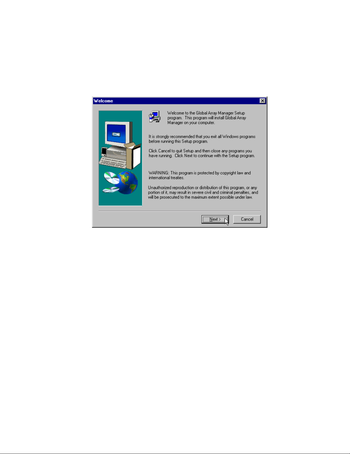
2. After a few moments, the Welcome dialog box will display
(Figure 2.1). Click Next to proceed with the installation, or click
Cancel to end the installation procedure and return to the menu.
Figure 2.1 Welcome Dialog Box
3. When the LSI Logic Software License Agreement screen displays,
click Yes to accept the terms of the agreement and continue.
If you click No, you will not be allowed to continue GAM TT Client
installation.
The Select Components dialog box is displayed as shown in Figure 2.2.
At this point you will select the component(s) you wish to install.
2-2 Installation
Version 1.0 Copyright © 2001-2003 by LSI Lo gic Corporation. All rights reser ved.
Page 17
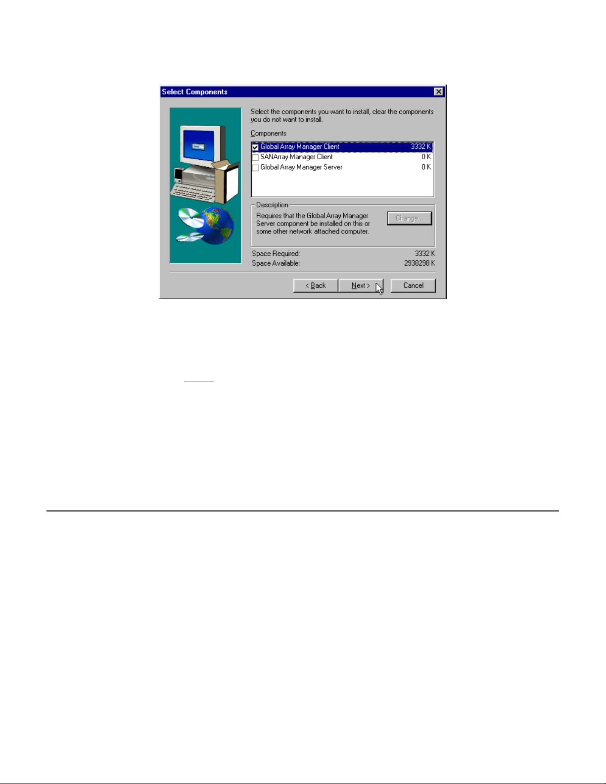
Figure 2.2 Select Components to Install
4. To select Global Array Manager Transition Tool Client for installation,
click the box (if necessary) to check the Global Array Manager
Transition Tool Client option.
Note:
5. Click Next and follow the on-screen prompts.
If installing the Global Array Manager Transition Tool Client,
you may also choose to install Global Array Manager
Transition Tool Server at this time. Instructions for GAM TT
Server installation are described in the Global Array
Manager Transition Tool Server Software Installation Guide
and User Manual.
2.3 Installing Global Array Manager Transition Tool Client with Linux
Installing the Global Array Manager Transition Tool Client on a Linux
operating system requires the use of Wine™. Wine is a program that
ports the GAM TT Client onto Linux. It is highly recommended that you
use the Wine version from the specified web site. This version of Wine
has been tested with GAM TT Client and we do not guarantee that our
product supports other versions.
Installing Global Array Manager Transition Too l Client with Linux 2-3
Version 1.0 Copyright © 2001-2003 by LSI Lo gic Corporation. All rights reser ved.
Page 18

2.3.1 Install Wine
Go to the following web site to download Wine:
http://www.rpmfind.net
It is highly recommended that you use the following Windows
16/32-bit emulator rpm file:
wine-20010131-3.i386.rpm
Refer to the following web sites for further information on Wine.
http://www.winehq.com
http://www.codeweavers.com
2.3.2 Install GAM TT Client
Global Array Manager Transition Tool software Global Array Manager
Transition Tool software can be downloaded from
http://www.lsilogic.com/GAMTT. Once you download GAM TT Client, use
the following procedure for installation (where x: represents the current
version number.):
\GAM\Linux\gam-client-x.xx-xx.i386.rpm
Install GAM TT Client on Linux:
rpm -ivh gam-5.00-xxxxxxxx.i386.rpm
GAM TT will be installed under /opt/gam
To run GAM TT Client see Section 3.1, “Star ting Global Array Manager
Transition Tool,” page 3-1. Fur ther information is available in the
README.TXT file.
2.3.3 To Uninstall GAM TT Client Software
1. Query the installed GAM TT Client software:
rpm -qa | grep gam
2. Uninstall GAM TT Client software:
rpm -e gam-5.00-xxxxxxxx
2-4 Installation
Version 1.0 Copyright © 2001-2003 by LSI Lo gic Corporation. All rights reser ved.
Page 19

Chapter 3
Startup and Navigation
3.1 Star ting Global Array Manager Transition Tool
Starting the Global Array Manager Transition Tool Client requires both
the Server and Client components. It is required that you install and start
GAM TT Server before you attempt to run the Global Array Manager
Client.
3.1.1 Server Component
Installation and startup of the Global Array Manager Server component
is covered in the Global Array Manager Server Software Installation
Guide and User Manual. The software for GAM TT Server is provided on
http://www.lsilogic.com/GAMTT.
Refer to the appropriate sections in the above-mentioned manual for
instructions on star ting the Global Array Manager Transition Tool Server
component under any of the supported network operating systems.
3.1.2 Client Component
Under Windows 2000/2003/XP 32-bit/95/98/Me or Linux, you are ready
to start the Global Array Manager Transition Tool Client once you have
installed the client on your workstation (see Section 2.2, “Installation of
the Global Array Manager Transition Tool Client,” page 2-1).
To star t GAM TT Client:
• Under 2000/2003/XP 32-bit/95/98/Me, start the GAM TT Client
software by selecting
Start->Programs->Mylex Global Array Manager Client.
• Under Linux, type gam.
Global Array Manager Transition Tool Client Software User’s Guide 3-1
Version 1.0 Copyright © 2001-2003 by LSI Lo gic Corporation. All rights reser ved.
Page 20
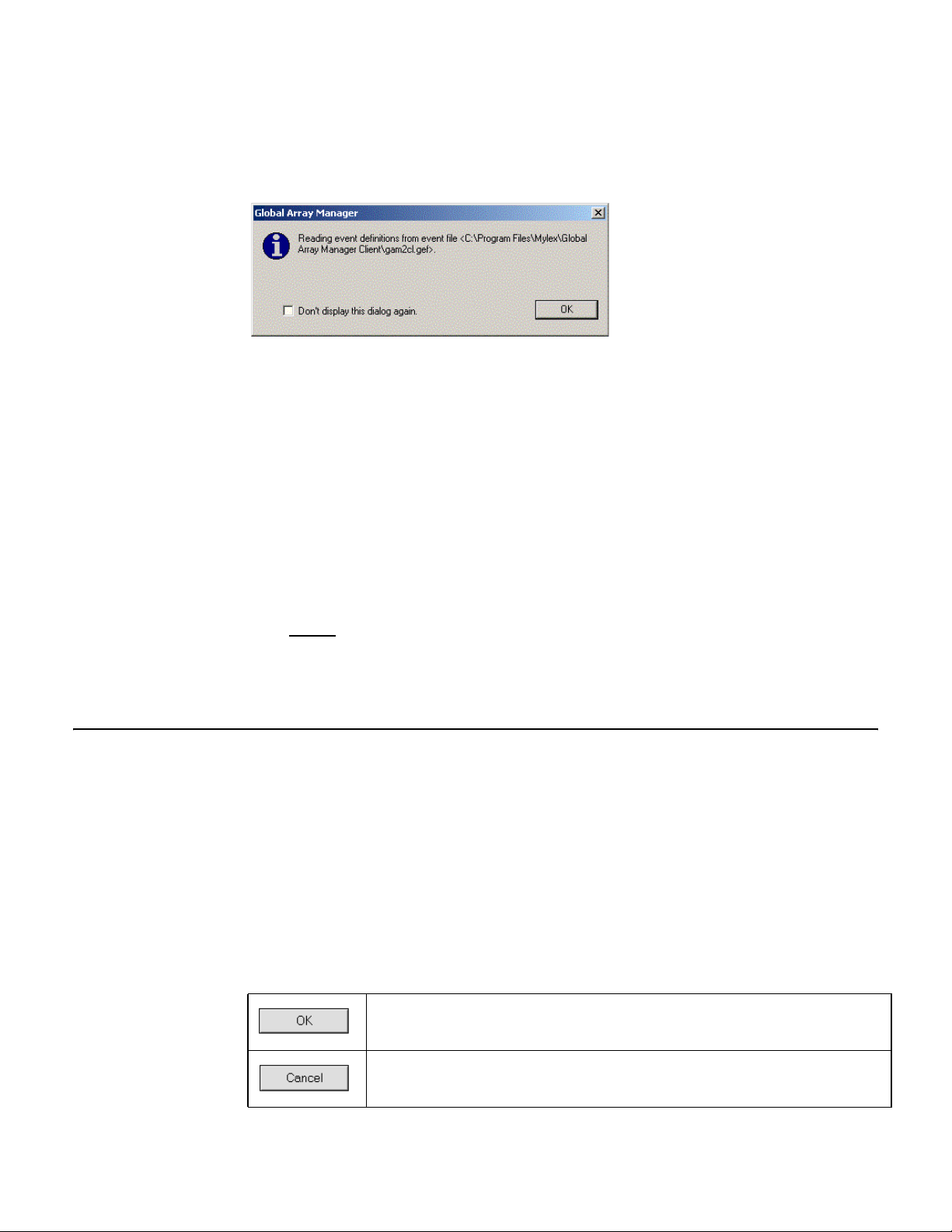
At startup, the GAM TT Client will display the following message dialog
box (Figure 3.1).
Figure 3.1 GAM TT Client Opening Message
This dialog box is to notify you that the event definition has been changed
from default after clicking OK from the Settings option. If you do not want
this dialog box to open each time you star t the GAM TT Client, select the
“Don’t display this dialog again” check box. Click OK to close the dialog
box.
If at least one server group and file server are defined, the GAM TT
Client opening screen displays. If not, the Define Server Groups dialog
box opens (see Section 3.5, “Setting Up Server Groups and Servers,”
page 3-17).
Note:
In order for event notification to occur, the Global Array
Manager Transition Tool Ser ver and Global Array Manager
Transition Tool Client must be r unning at all times.
3.2 Navigating Global Array Manager Transition Tool Client
This section describes the navigating features and options that GAM TT
provides.
3.2.1 Button Controls
Dialog boxes throughout the Global Array Manager Transition Tool Client
have a series of control buttons. Some examples of these include:
Click this button to apply the settings made in the dialog box.
Click this button to cancel the settings made in the dialog box.
3-2 Startup and Navigation
Version 1.0 Copyright © 2001-2003 by LSI Lo gic Corporation. All rights reser ved.
Page 21
Click this button to confirm the action identified in the dialog box.
Click this button to cancel the action identified in the dialog box.
Click this button to close the active dialog box.
Click this button to apply your configuration changes.
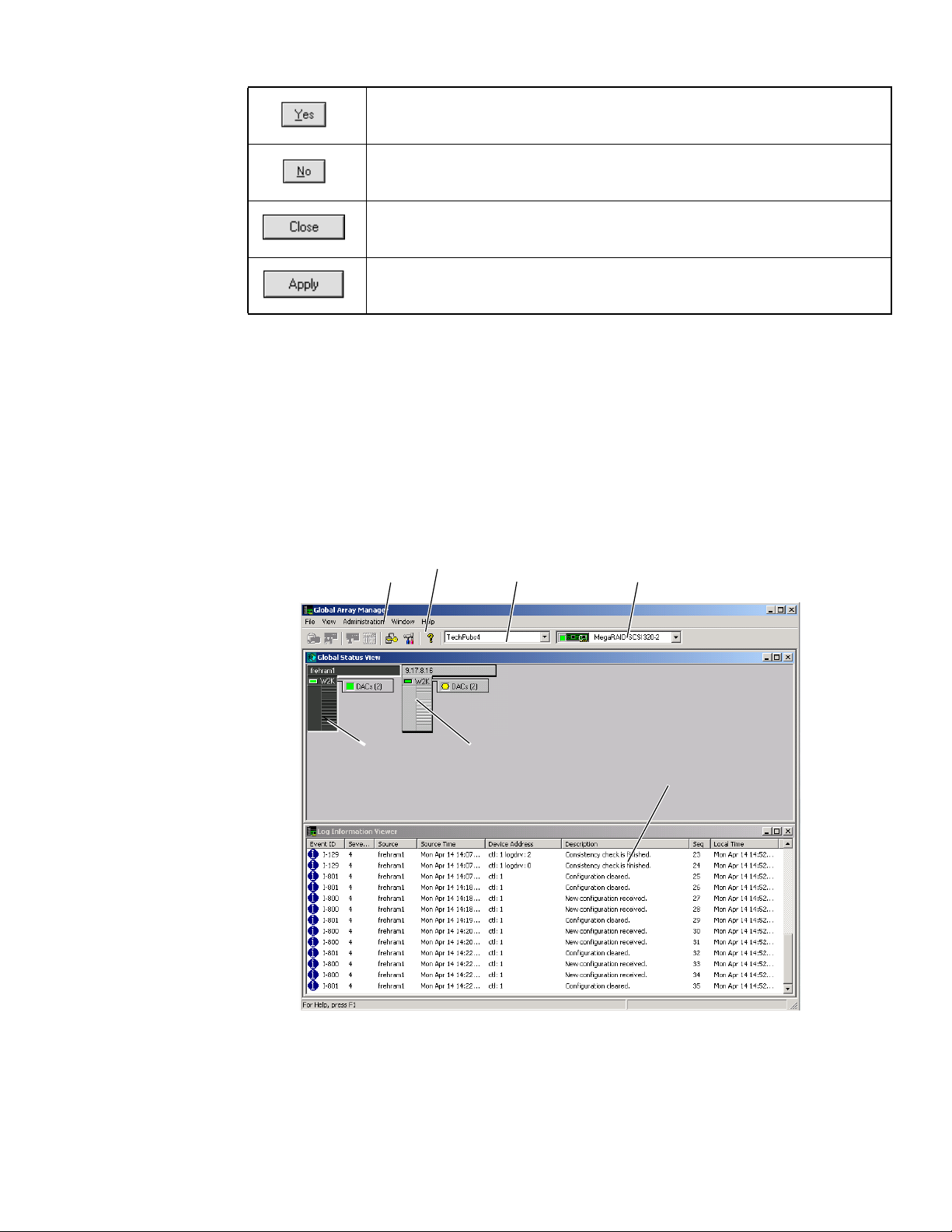
3.2.2 Components of the GAM TT Client Opening Screen
Upon startup (with defined ser vers), Global Array Manager Transition
Tool Client displays the opening screen, consisting of the Global Array
Manager window, the Global Status View window, and the Log
Information Viewer (Figure 3.2).
Figure 3.2 Opening GAM TT Screen
#1
#5
#2
#3 #4
#6
#7
Navigating Global Array Manager Transition Tool Client 3-3
Version 1.0 Copyright © 2001-2003 by LSI Lo gic Corporation. All rights reser ved.
Page 22

3.2.2.1 Components of the GAM TT Client Windows
The major components of the GAM TT Client windows (Figure 3.2) are
described below.
1. Item #1 is the menu bar. There are five menus with several
selections each. The contents of the menus and the functionality of
several of the most important selections will be described throughout
this guide.
2. Item #2 is the toolbar. There are seven toolbar icons representing
eight of the most useful functions available in GAM TT Client. The
identity of each toolbar icon and an explanation of the purpose of
each will be described in later sections of this chapter.
3. Item #3 is the server group selection box. When selected, the box
displays the names of each server group that is in contact with the
current client workstation. Each group may consist of multiple
servers. You may select a specific server group to view, or select “All
Servers” if you want to view all the servers that are connected to this
workstation.
4. Item #4 is the controller selection box. When selected, the box
displays the controller ID (C-0, C-1, etc.) and controller type
(eXtremeRAID 2000, etc.) of each PCI/SCSI connected to the
currently-selected server.
3.2.2.2 Components of the Global Status View Window
The major components of the Global Status View window (Figure 3.2)
are described below:
5. Item #5 is an icon that represents the currently-selected file server
running the GAM TT Server component. The icon identifies:
– the IP address (e.g. 10.17.3.172) or name (e.g. ide40) of the
server
– the network operating system running on the ser ver (e.g. 2000 =
Windows 2000; NW = Novell NetWare, etc.)
– the operational status of the server (green = functioning, yellow
= attempting connection, red ‘X’ = unable to connect)
3-4 Startup and Navigation
Version 1.0 Copyright © 2001-2003 by LSI Lo gic Corporation. All rights reser ved.
Page 23

– the number of DAC (PCI/SCSI) controllers connected on the
server, with a controller operational status light (green =
functioning, yellow = critical, red ‘X’ = down or nonfunctional)
6. Item #6 is an icon that represents a currently unselected file server
running the GAM TT Server component. The icon identifies the same
information described above.
3.2.2.3 Components of the Log Information Viewer
7. Item #7 in Figure 3.2 is the GAM TT Client Log Information Viewer.
Each line in the Log Information Viewer identifies a single event
(error, status, warning, etc.) which was noted during monitor ing by a
file server running GAM TT Ser ver, and was transmitted by that
server to this client workstation. Relevant details accompany the
event:
– Event ID. Displays an icon showing whether the event is
informational, cautionary, a warning, etc., plus the identification
number assigned to this event.
– Severity. The severity level of this event.
– Source. The IP address or name of the file server that is the
sender (source) of this event.
– Source Time. Day of the week, month, day of the month, time
of day, and year at the source file server’s location when this
event occurred.
– Device Address. Relevant channel/target or other data
pertaining to the source of this event.
– Description. Text of the message describing what occurred.
– Sequence (Seq). Number representing where this event fell in a
stream of events from the same source.
– Local Time. Day of the week, month, day of the month, time of
day, and year at the local client workstation’s location when this
event arrived.
Navigating Global Array Manager Transition Tool Client 3-5
Version 1.0 Copyright © 2001-2003 by LSI Lo gic Corporation. All rights reser ved.
Page 24
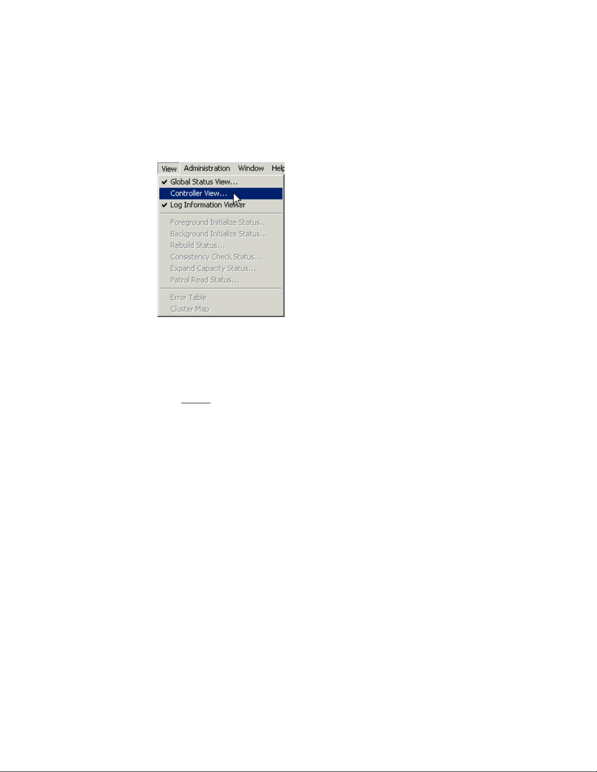
3.2.3 Components of the Controller View Window
Open the Controller View window by double-clicking any server icon in
the Global Status View, or as shown in Figure 3.3:
Figure 3.3 Select “Controller View”
The Controller View window (Figure 3.4), displays the following
information about the controller currently selected in the controller
selection box:
Note:
In order for the Controller View window to refresh with real
time information, if you don’t have a real IP address on the
GAM TT Server, it is important to make sure that the GAM
TT Server event notification destination address is set with
the loop back IP address (127.0.0.1). See the Global Array
Manager Transition Tool Server Software Installation Guide
and User Manual for instructions on how to update the
server event file (gamscm.ini).
• Item #1: The number of channels on this controller, each channel
depicted as a tower.
• Item #2: The physical devices present on each channel, specifying
the target ID, capacity of the device, device type, and device status.
See Section 5.4, “Physical Device and Logical Drive Monitoring,”
page 5-5, for more information.
• Item #3: The logical drives configured on the controller, specifying
the logical drive number, capacity of the logical drive, configured
RAID level, and logical drive status.
3-6 Startup and Navigation
Version 1.0 Copyright © 2001-2003 by LSI Lo gic Corporation. All rights reser ved.
Page 25
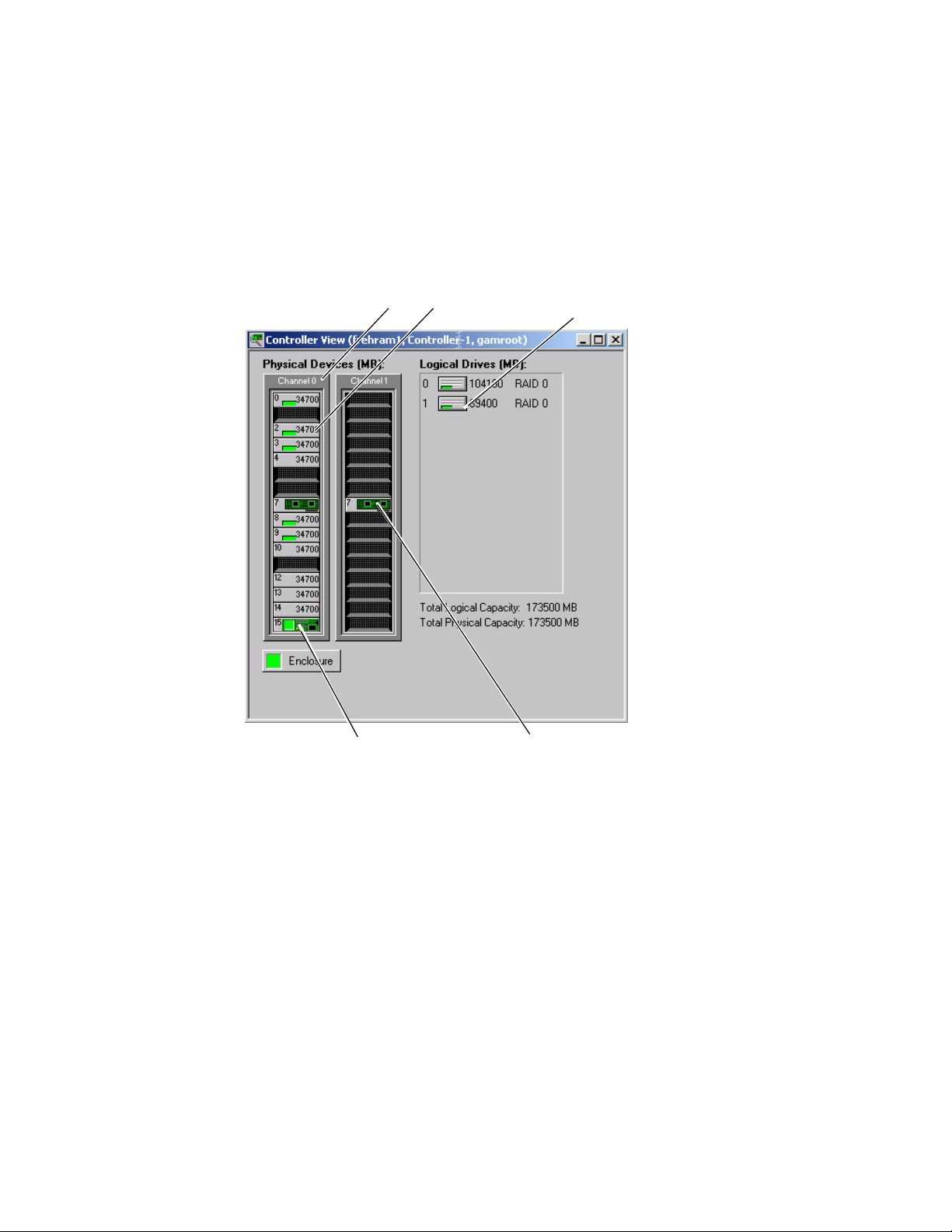
• Item #4: The enclosure device present on each channel, specifying
the device inquiry data (vendor, bus width, etc...), and the device
state.
• Item #5: The host device present on each channel, specifying the
device inquiry data (vendor, bus width, etc...), and the device state.
Figure 3.4 Controller View Window – “Non-Fibre” RAID Controller
#1 #2
#4
#3
#5
3.2.3.1 eXtremeRAID 3000
The Controller View window for the eXtremeRAID 3000 (Figure 3.5),
displays the same information as descr ibed in the previous section.
However, it is organized graphically to allow many more targets to be
shown in each of the fibre channels, and the Controller Vie w is scrollab le .
The number of targets per column can be set in the GAM2CL.INI file.
Channel 0 represents the internal SCSI channel.
Navigating Global Array Manager Transition Tool Client 3-7
Version 1.0 Copyright © 2001-2003 by LSI Lo gic Corporation. All rights reser ved.
Page 26
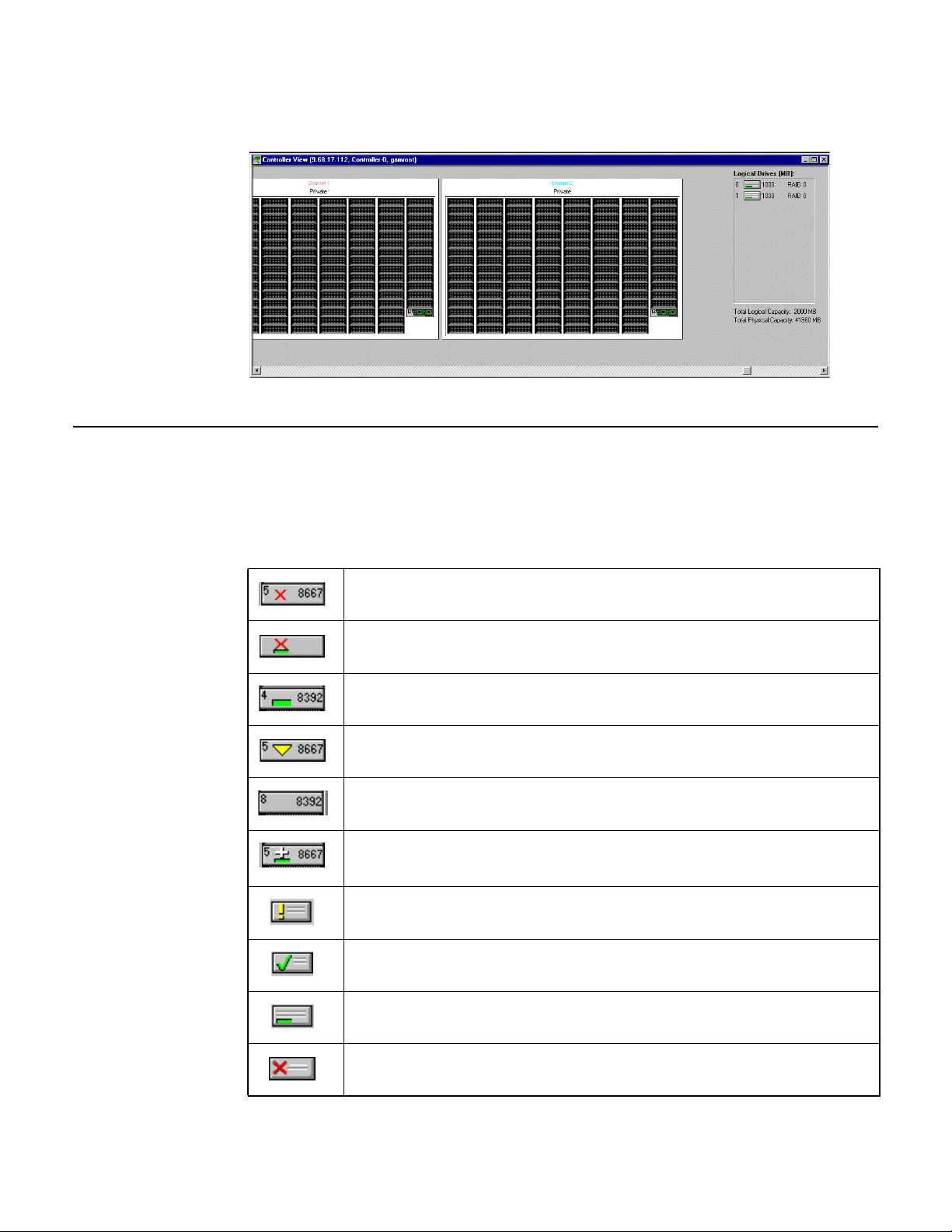
Figure 3.5 Controller View Window – eXtremeRAID 3000
3.3 Status Icons
Controller
The following icons display the status of logical and physical devices in
the Controller View Window:
Physical Device Offline State
Physical Device Temporary Offline Sta te
Physical Device Online State (configured)
Physical Device Rebuild State
Physical Device Unconfigured
Global Spare Physical Device (Dedicated spare de vice is the same
except the shade of the cross changes)
Logical Drive Critical State
Logical Drive Consistency Check State
Logical Drive Online State (configured)
Logical Drive Offline State
3-8 Startup and Navigation
Version 1.0 Copyright © 2001-2003 by LSI Lo gic Corporation. All rights reser ved.
Page 27
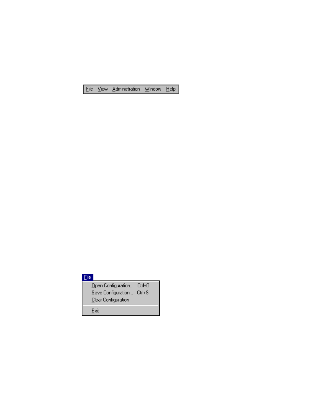
3.3.1 Menu Bar and Menus
GAM TT Client contains a menu bar (Figure 3.6) in the Global Array
Manager Transition Tool window.
Figure 3.6 Menu Bar
3.3.1.1 File Menu
The File menu (Figure 3.7) contains the following options:
• Open Configuration (Ctrl+O): Loads a configuration from disk and
saves it to the controller. (See Section 3.5, “Setting Up Ser ver
Groups and Servers,” page 3-17.)
• Save Configuration (Ctrl+S): Saves a configuration file to a new
filename, disk, and/or directory.
• Clear Configuration: Removes configuration information from the
selected array on the selected controller.
Caution:
Although there are confirmation checkpoints and warnings
following selection of this option, remember that all existing
configuration and file data (on all drives connected to the
array) will be deleted.
• Exit: Exits the GAM TT Client.
Figure 3.7 File Menu
Status Icons 3-9
Version 1.0 Copyright © 2001-2003 by LSI Lo gic Corporation. All rights reser ved.
Page 28
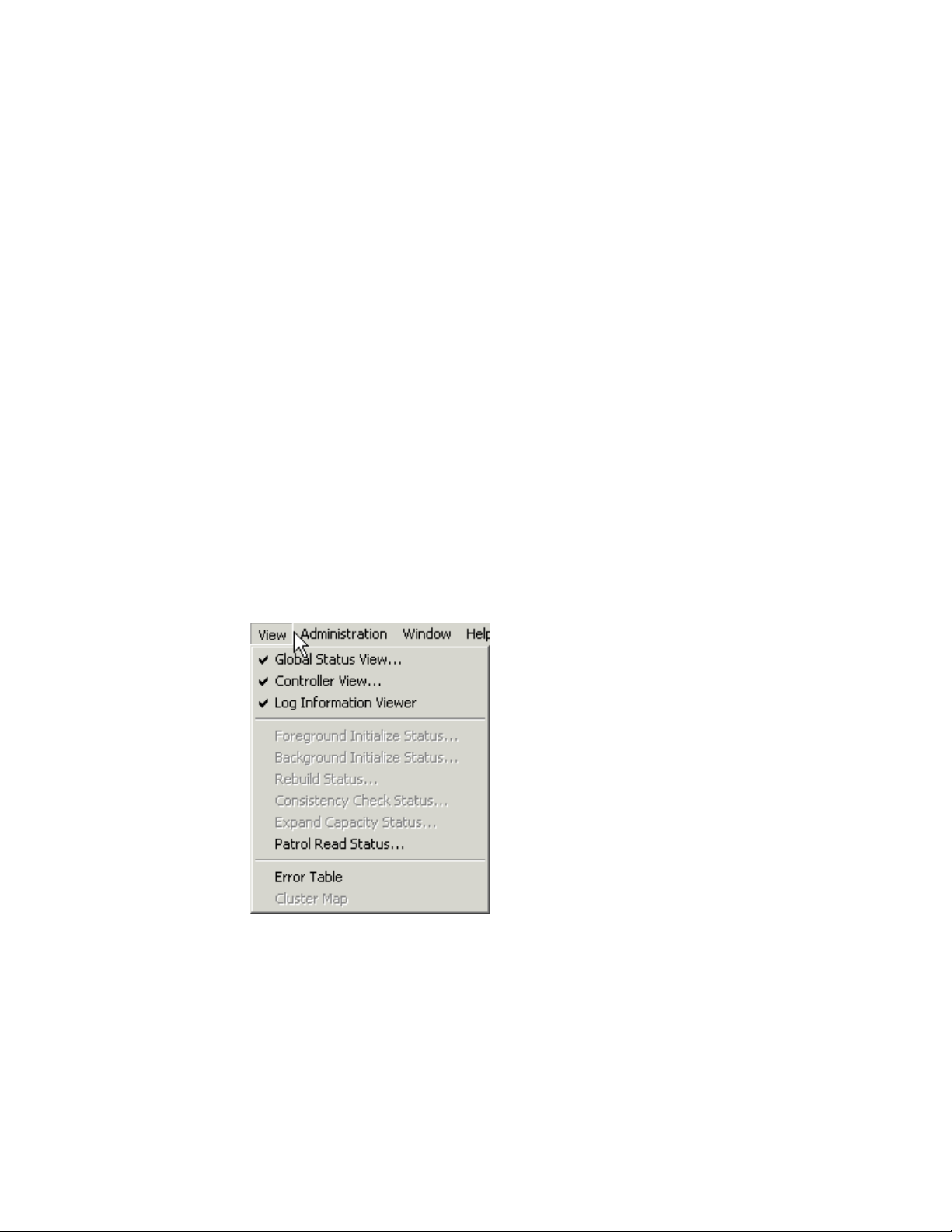
3.3.1.2 View Menu
The View menu (Figure 3.8) contains the following options:
• Global Status View: Toggles the Global Status View window. The
• Controller View: Toggles the Controller View window showing
• Log Information Viewer: Toggles the Log Information Viewer, a
Global Status View window opens by default when Global Array
Manager Transition Tool Client star ts.
channel/ID/target information and physical device/logical drive
configurations for the controller selected in the controller selection
box.
window showing a log of recent system error and status event
messages. The Log Information Viewer opens by default when
Global Array Manager Transition Tool Client starts.
• Foreground Initialization Status: Displays the progress (percent
complete) of an ongoing full foreground initialization of one or more
drives.
Figure 3.8 View Menu
• Background Initialization Status: Displays the progress (percent
complete) of an ongoing full background initialization of one or more
drives.
• Rebuild Status: Displays the progress (percent complete) of an
ongoing device rebuild.
3-10 Startup and Navigation
Version 1.0 Copyright © 2001-2003 by LSI Lo gic Corporation. All rights reser ved.
Page 29

• Consistency Check Status: Displays the progress (percent
complete) of an ongoing logical drive consistency check.
• Expand Capacity Status: Displays the progress (percent complete)
of an ongoing data restriping process across the target RAID group.
• Patrol Read Status: Enables GAM TT Client to poll every 1 minute
to get new status data from the controller.
• Error Table: Displays a table of bad block and “request sense” data
generated as a result of finding areas of damage or data
unavailability on a storage device. Data for all storage devices on the
selected controller are presented in the same tables.
• Cluster Map (Mylex Controllers Only): Displays a graphical back
end cable connection for the controller selected from the cluster
controller list.
3.3.1.3 Administration Menu
The Administration menu (Figure 3.9) contains the following options:
• Sign On: Enables use of GAM’s configuration and administration
functions to “Administrators” (“gamroot” + password). Enables only
monitoring functions to “Users.”
• Define Server Groups: Sets up server groups and individual server
names or IP addresses within each group.
• Select Current Server Group (Ctrl+G): Displays the current
contents of the server selection box located in the Global Array
Manager Transition Tool window. Functions in the same way as
directly selecting the server selection box.
• Select Current Controller (Ctrl+C): Displays the current contents of
the controller selection box located in the Global Array Manager
Transition Tool window. Functions in the same way as directly
selecting the controller selection box.
• RAID Assist: Mylex’s built-in RAID Controller configuration utility.
Facilitates configuration tasks using either one-step “automatic”
configuration, a configuration “wizard” assistant, or a manual
(advanced level) configuration option allowing more control over
configuration parameters.
Status Icons 3-11
Version 1.0 Copyright © 2001-2003 by LSI Lo gic Corporation. All rights reser ved.
Page 30
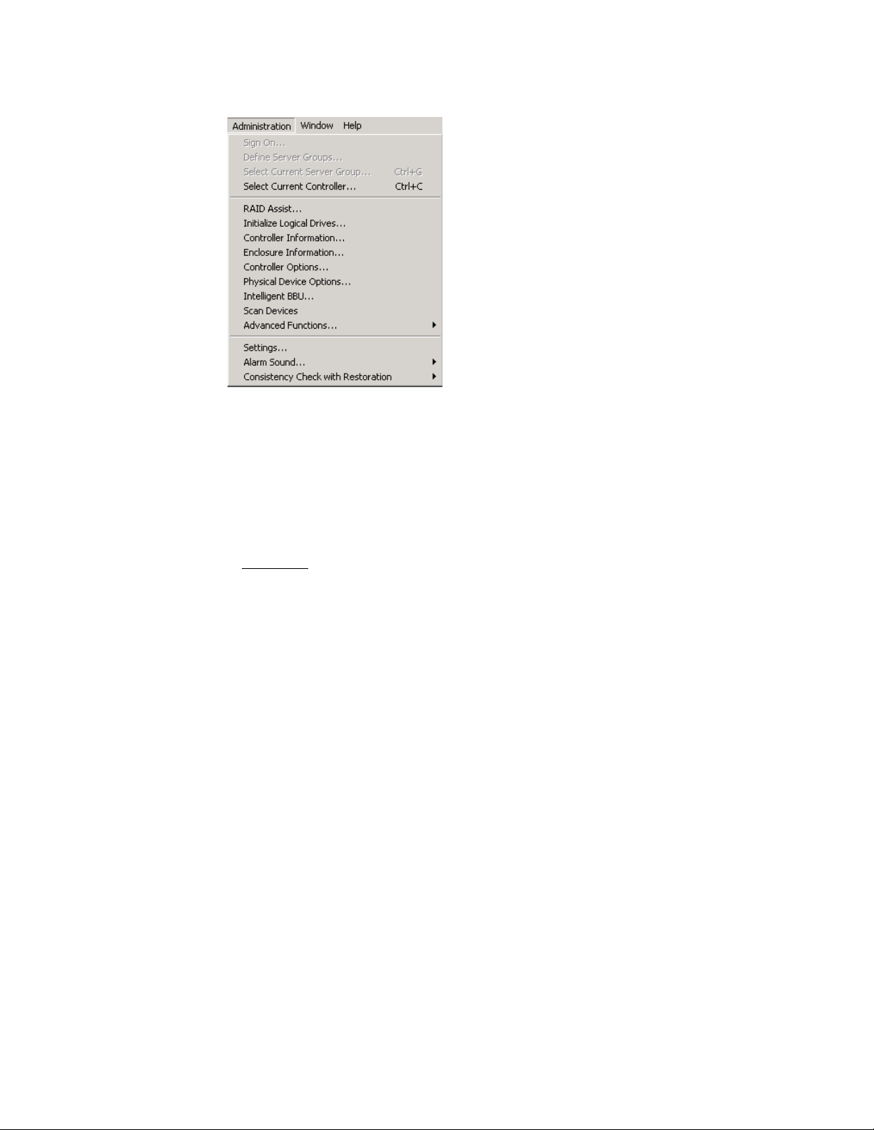
Figure 3.9 Administration Menu
• Initialize Logical Drives: Offers the ability to run a full initialization
of logical drives at a time of your choice, not just immediately
following a new configuration. If it’s inconvenient to follow a
configuration immediately with a logical drive initialization, you can
decline the initialization and use this menu item to start the process
at a later time.
Caution:
If you perform an initializ ation on a logical drive(s) that you
are currently using for data storage, you will lose the data
stored on the drive(s).
• Controller Information: Displays key information about the
currently-selected controller.
• Enclosure Information: Displays information and status about
components in the external disk enclosure.
• Controller Options: Sets various parameters for the selected Disk
Array Controller. Unlike Controller Inform ation, user definable
controller parameters are modified in Controller Options.
• Physical Device Options: Displays a list of all physical devices
connected on the currently selected controller and allows the user to
change transfer speed, transfer width, and/or tag value for individual
devices.
• Intelligent BBU: (Only enabled if the selected controller has an
Intelligent Battery Backup Unit installed.) Displays a dialog box from
which you can do the following:
3-12 Startup and Navigation
Version 1.0 Copyright © 2001-2003 by LSI Lo gic Corporation. All rights reser ved.
Page 31

– Monitor the power remaining in the Intelligent BBU (Mylex
Controllers Only).
– Set the low power threshold (Mylex Controllers Only).
The Intelligent BBU features and functionality are described in detail
elsewhere. GAM TT simply offers a way of keeping up-to-date as to
the condition and charge in the battery.
• Scan Devices: Scans for ne w de vices that ha v e recently been added
and which are not currently identified within GAM TT Client.
• Advanced Functions: Opens a submenu from which you can select
the following option:
– Flash Utility: Provides the ability to upgrade controller firmware,
BIOS, boot block, or BIOS configuration utility as new
maintenance releases become available.
• Settings: Opens a tabbed dialog box in which you can specify the
Alert/Alar m, Communication, and Event Editor settings that you
desire. Examples of such settings include type of alarm, such as
pager, fax, E-mail, etc., modem baud rate, COM port, stop bits, data
bits, parity, event severity level, event message editing, and so on.
• Alarm Sound (MegaRAID Controllers Only): Opens a submenu
where you can select to Enable, Disable, or Silence the audible
alarm. Refer to your controller hardw are guide for a description of the
audible warnings and their meaning.
• Consistency Check with Restoration (MegaRAID Controllers
Only): Opens a submenu where you can select Enable, or Disable
the consistency check with Restoration. Enable is the default setting,
when a consistency check is perfor med and inconsistent data is
found, that data will be restored. When Disabled, a bad block table
will be prepared for inconsistent data.
3.3.1.4 Window Menu
The Window menu (Figure 3.10) is a standard feature of Windows .NET
32-bit, XP 32-bit, Windows Me, Windows 95/98, Windows 2000, and
Windows NT. It is implemented as such in GAM TT.
Status Icons 3-13
Version 1.0 Copyright © 2001-2003 by LSI Lo gic Corporation. All rights reser ved.
Page 32

Figure 3.10 Window Menu
3.3.1.5 Help Menu
The Help menu (Figure 3.11) identifies the on-line help options available
within the Global Array Manager Transition Tool Client.
• Contents (F1): Displays a list of available help topics.
• About Global Array Manager: Displays the Windows standard
“About” box.
Figure 3.11 Help Menu
3.3.2 Toolbar and Toolbar Icons
GAM TT Client contains a toolbar (Figure 3.12) in the Global Array
Manager Transition Tool window.
Figure 3.12 Toolbar
3-14 Startup and Navigation
Version 1.0 Copyright © 2001-2003 by LSI Lo gic Corporation. All rights reser ved.
Page 33

Each toolbar button corresponds to a function available from the menu
bar.
Disk Configuration Wizard: Brings up the RAID Assist dialog box
for RAID controller configuration.
Scan Devices: Scans for new, recently added devices which are
not yet identified within GAM TT.
Displays Controller Information: Displays key information about
the currently-selected RAID Controller or HBA.
Error Table: Displays a table of “request sense” data.
Sign-On: Enables configuration and administration functions to
Administrators and monitoring functions to “Users.”
Settings for Events: Opens a dialog box for specifying the
Alert/Alar m, Communication, and Event Editor settings that you
desire.
Help Contents: Displays the on-line help contents page.
3.4 Exiting Global Array Manager Transition Tool
Exit Global Array Manager Transition Tool Client as shown in Figure 3.13:
Figure 3.13 Select “Exit”
Note:
We recommend leaving the GAM TT Client running as long
as there are servers you wish to monitor or configure. If yo u
do exit, you will be unable to receive events from GAM TT
Server and you will not be informed of errors or status
Exiting Global Array Manager Transition Too l 3-15
Version 1.0 Copyright © 2001-2003 by LSI Lo gic Corporation. All rights reser ved.
Page 34

unless you restart GAM TT Client and reconnect to the
server(s).
3.4.1 Exiting GAM TT Server
Refer to the Global Array Manager Transition Tool Server Software
Installation Guide and User Manual for details on how to exit GAM TT
Server.
3-16 Startup and Navigation
Version 1.0 Copyright © 2001-2003 by LSI Lo gic Corporation. All rights reser ved.
Page 35

3.5 Setting Up Server Groups and Servers
3.5.1 Adding a Server Group to the Server Group List
Open Define Server Groups as shown in Figure 3.14. (This is not
necessary if you are starting GAM TT and no Server Groups are defined.
The Define Server Groups dialog box will display automatically.)
Figure 3.14 Select “Define Server Groups”
In the Define Server Groups dialog box (Figure 3.15), do the following:
1. Click the Add button under the Server Groups section of the dialog
box.
Figure 3.15 Define Server Groups Dialog Box
Setting Up Server Groups and Servers 3-17
Version 1.0 Copyright © 2001-2003 by LSI Lo gic Corporation. All rights reser ved.
Page 36

2. In the Adding Item dialog box, type the name of the server group that
you are adding.
3. Click OK. The Define Server Groups dialog bo x will reappear with the
newly-defined server group added.
Note:
The Discovered gr oup contains a list of all server hosts that
are sending events to the client.
3.5.2 Adding a Server to the Server Groups List
With the Define Server Groups dialog box open (Figure 3.15), do the
following:
1. Click the Add button under the Servers section of the dialog box.
2. In the Adding Item dialog box, type the IP address of the server that
you are adding. If you’re running GAM TT Client under Windows
2000/2003/XP 32-bit/95/98/Me or Linux, you may instead type the
name of the server.
3. Click OK. The Define Server Groups dialog bo x will reappear with the
newly-defined server added.
4. To add more ser vers to the group, repeat steps 1 through 3.
5. Click OK in the Define Server Groups dialog box when you are
finished.
After adding servers, Global Array Manager Transition Tool returns to the
Global Status window.
Note:
Select “All Servers” to see all servers in the Global Status
view.
3-18 Startup and Navigation
Version 1.0 Copyright © 2001-2003 by LSI Lo gic Corporation. All rights reser ved.
Page 37

3.6 Signing On to a Server
This section describes the different server access lev els and the methods
of signing onto the Global Array Manager Transition Tool Client.
3.6.1 Security Access Levels
The ability to perform certain actions within the GAM TT Client depends
on your security access level. There are three levels of security access,
Guest (no sign-on), User, and Administrator.
3.6.1.1 Guest
Note:
Guest access lev el is achieved by not signing on to a server host. Guests
can monitor the Log Information Viewer and the Global Status View.
Guests cannot view or make changes to any controller parameters or
configurations.
Do not confuse GAM’s Administrator access level with the
Windows’ log on name “Administrator,” they are not the
same. The password “gamroot” is required to be
established as a user on the server host. It is
recommended that the “gamroot” user be established with
Windows’ “Administrator” privileges or Linux’s root
privileges. The “gamroot” account must be password
protected and the password must be managed in a security
conscious manner. GAM TT relies on the server host’s
operating system security measures. Therefore, proper
handling of the “gamroot” password is critical to the
protection of user data on the controller.
3.6.1.2 User
User access level is achieved by signing on to a server host using a
username that is not “gamroot,” but one that the administrator of that
server assigns. Users have all the capabilities of Guests. Users can also
view the detailed status of a controller by activating the Controller View,
Controller Information and Enclosure Information. Users cannot view or
make changes to any controller parameters or configurations.
Signing On to a Server 3-19
Version 1.0 Copyright © 2001-2003 by LSI Lo gic Corporation. All rights reser ved.
Page 38

3.6.1.3 Administrator
Administrator access level is achieved by signing on to a ser ver host
using the username “gamroot”; use of a password is highly
recommended. Administrators have the capabilities of Guests and Users
plus the full privilege to view and change the status and settings of the
selected controller and other internal GAM TT settings.
3.6.2 Signing On
To gain access to capabilities beyond Guest access level, you must sign
on to a server host.
Double-click a host icon in the Global Status View (Controller View must
be closed first).
• The Sign On dialog opens if you have never signed on during this
session or if you did not check the Sign On dialog’s Remember
password box on the previous sign on (see Figure 3.16).
• If you have previously signed on and did check the Remember
password box then the previously entered username and password
will automatically be used for this new sign on.
Figure 3.16 Sign On Dialog Box
If the sign on fails, the Sign On dialog will open to allow adjustment of
the username and/or password or you may open Sign On at any time as
shown in Figure 3.17.
3-20 Startup and Navigation
Version 1.0 Copyright © 2001-2003 by LSI Lo gic Corporation. All rights reser ved.
Page 39

Figure 3.17 Select “Sign On”
GAM’s internal operation during Sign On is to:
1. Encrypt the username and password and send them to the GAM TT
Server running on the selected server host.
2. The GAM TT Server receives and decrypts the username and
password and makes an operating system specific call to validate
them per the server host’s operating system’s user accounts.
3. After the username and password are validated by the operating
system the username is compared to the string “gamroot”. If the
username matches, sign on is granted Administrator access level.
4. The GAM TT Server notifies GAM TT Client of the success or failure
of the sign on attempt and whether or not that sign on attempt has
been granted Administrator access level.
Do the following to sign on to a server:
1. Type a username and password of your choice that are previously
enabled on the server host.
This will provide access privileges appropriate for the username.
2. Check the “Remember password for this session” box if you want
GAM TT to refrain from Sign On messages each time you select a
server during this session which uses the same password. This
amounts to an automatic sign-on to additional servers and should be
used with caution.
Signing On to a Server 3-21
Version 1.0 Copyright © 2001-2003 by LSI Lo gic Corporation. All rights reser ved.
Page 40

Uncheck the box if you want to retain the option of signing on to each
server you wish to access individually.
3. Click the Sign-On button (see Figure 3.16).
3.7 Setting and Modifying User Preferences
Open Settings by clicking Administration->Settings on the menu bar or
the Preferences icon as shown in Figure 3.18.
Figure 3.18 Select “Settings”
3-22 Startup and Navigation
Version 1.0 Copyright © 2001-2003 by LSI Lo gic Corporation. All rights reser ved.
Page 41

3.7.1 Aler t Preferences
Figure 3.19 Settings Dialog Box – Alert Preferences
In the Settings dialog box, under the Alert Preferences tab (Figure 3.19),
you have several options:
3.7.1.1 Event Log
• Append events to your current log file, or
• Replace the log file (overwrite it)
• Rename the log file
• Enable or disable the event logging function
3.7.1.2 Enable Global Alerts for Severity Level(s)
• For each type of alarm (Email, Pager, Fax, Launch Application, and
Alarm Sound) check the box(es) corresponding to the event severity
level(s) for which you would like to enable this type of alarm globally.
For example, in Figure 3.19, all Level 0 and Level 1 messages/event s
will result in an alarm sound locally, and E-mail, page (Level 0 only),
and fax to those individuals identified in Alarm Setup.
Setting and Modifying User Preferences 3-23
Version 1.0 Copyright © 2001-2003 by LSI Lo gic Corporation. All rights reser ved.
Page 42

Finish by doing one of the following:
• Click OK to accept the global alert settings and exit the Settings
• Click Cancel to leave original settings unchanged, or
• Click another Settings tab to set additional user preferences.
3.7.2 Alarm Setup
The top half of the Alarm Setup dialog box lists the types of alarms that
can be used (Pager, Fax, E-mail, Launch Application). The lower half of
the Alarm Setup dialog box lists the currently defined
destinations/recipients/applications for the alarm type selected in the
upper window (Figure 3.20).
Events are numbered from 0 for most severe to 4 for least severe,
and can be edited by the user.
dialog box, or
Note:
Email requires MAPI- or SMTP-compliant messaging (e.g.
Microsoft Outlook), as well as Microsoft Exchange.
Figure 3.20 Settings Dialog Box – Alarm Setup
3-24 Startup and Navigation
Version 1.0 Copyright © 2001-2003 by LSI Lo gic Corporation. All rights reser ved.
Page 43

3.7.2.1 Add a Pager
1. Select the Pager alarm type in the upper window.
2. Click Add.
Figure 3.21 Pager Setup Dialog Box
The Pager setup box is displayed as shown in Figure 3.21.
3. In the Pager box:
– Enable or disable this Pager entry using the Enabled check box.
– Type the Modem Setup String, or keep the default.
– Type a Pager Prefix, or keep the default.
– Type the phone number of someone who will receive a page.
– Type a Pager Suffix if needed.
– Type a Pager Delay interval. The value of each comma is 1
second.
– Type the Modem Hang-up String, or keep the default.
Note:
Please consult your modem manufacturer or modem
documentation for the specific strings which work best with
your modem.
– Select the appropriate button for a Numeric or Alphanumeric
pager.
Setting and Modifying User Preferences 3-25
Version 1.0 Copyright © 2001-2003 by LSI Lo gic Corporation. All rights reser ved.
Page 44

4. If you need to enter a Message Prefix, Suffix, or Delay interval, click
Advanced. Type the desired information and click OK to return to the
Pager setup box.
5. To test the pager using the settings you’ve input, click Test.
6. When you are satisfied with the Pager you’ve set up, click OK.
Your new Pager entry displays in the lower window of the Alarm
Setup dialog box. (Refer to Figure 3.20 for an example.)
3.7.2.2 Remove a Pager
1. Select the Pager alarm type in the upper window of Alarm Setup.
2. Select the Pager entry to remove in the lower window of Alarm
Setup.
3. Click Remove.
A confirmation message is displayed as shown in Figure 3.22.
Figure 3.22 Remove Pager Entry Message
4. Click Yes to remove the Pager entry, or click No to keep the entry.
3.7.2.3 Add a Fax Using Windows
For fax notification Microsoft Exchange and Microsoft At Work Fax
software must be installed on your system. GAM TT supports only
Microsoft At Work Fax under Windows 95. The Software field is not
selectable.
The required fax software components should already be available as
part of the nor mal Windows installation.
To add a fax, follow these steps.
1. Select the Fax alarm type in the upper window of the Alar m Setup
dialog box (Figure 3.23).
3-26 Startup and Navigation
Version 1.0 Copyright © 2001-2003 by LSI Lo gic Corporation. All rights reser ved.
Page 45

Figure 3.23 Fax Alarm Setup
2. Click Add.
The Fax setup box is displayed as shown in Figure 3.24.
Figure 3.24 Fax Setup Dialog Box
3. In the Fax box:
– Enable or disable this Fax entry using the Enabled check box.
– Type the fax phone number of someone who will receive a fax.
– Type a fax header, if desired.
4. To test the fax using the settings you have input, click Test.
5. When you are satisfied with the Fax you have set up, click OK.
Your new Fax entr y displays in the lower window of the Alarm Setup
dialog box. (Refer to Figure 3.23 for an example.)
Setting and Modifying User Preferences 3-27
Version 1.0 Copyright © 2001-2003 by LSI Lo gic Corporation. All rights reser ved.
Page 46

3.7.2.4 Remove a Fax
1. Select the Fax alarm type in the upper window of Alar m Setup.
2. Select the Fax entry to remove in the lower window of Alarm Setup.
3. Click Remove.
4. At the confirmation message, click Yes to remove the Fax entr y, or
click No to keep the entry.
3.7.2.5 Add a Fax Using Linux
When using Linux, the behavior of the Fax Alert function is defined in
gam2cl.ini file as follows, which is located under “~User/.gam/”.
Note:
If you are using a fax utility program other than “fax,” you
may need to modify the FAXUSERSCRIPT accordingly.
[COMM_SECTION]
...
FAXUSERSCRIPT=/usr/bin/fax DEV=ttyS0 NAME=%H send %N %M
...
where,
%H is replaced with header string
%N is replaced with phone number to dial
%M is replaced with message file name
3.7.2.6 Add an Email Using Windows
1. Select the E-mail alarm type in the upper window of the Alarm Setup
dialog box (Figure 3.25).
3-28 Startup and Navigation
Version 1.0 Copyright © 2001-2003 by LSI Lo gic Corporation. All rights reser ved.
Page 47

Figure 3.25 Email Alarm Setup
2. Click Add.
The E-mail setup box is displayed as shown in Figure 3.26.
Figure 3.26 Email Setup Dialog Box
3. In the Email box:
– Enable or disable this Email entry using the Enabled check box.
– Type the email address of someone who will receive an email.
– Type the subject of the email.
4. To test the email using the settings you’ve input, click Test.
5. When you are satisfied with the Email you’ve set up, click OK.
Your new E-mail entry displays in the lower window of the Alarm
Setup dialog box. (Refer to Figure 3.25 for an example.)
Setting and Modifying User Preferences 3-29
Version 1.0 Copyright © 2001-2003 by LSI Lo gic Corporation. All rights reser ved.
Page 48

3.7.2.7 Remove Email
1. Select the Email alarm type in the upper window of Alarm Setup.
2. Select the Email entry to remove in the lower window of Alarm Setup.
3. Click Remove.
4. At the confirmation message, click Yes to remove the Email entry, or
click No to keep the entry.
3.7.2.8 Add an Email Using Linux
When using Linux, the behavior of the E-mail Alert function is defined in
gam2cl.ini file as follows, which is located under “~User/.gam/”.
[COMM_SECTION]
...
EMAILUSERSCRIPT=/usr/bin/mail -s “%S” %R < %M
...
where,
%S is replaced with subject string
%R is replaced with recipients
%M is replaced with message file name
3.7.2.9 Add an Application to Launch
1. Select the Launch Application alarm type in the upper window of the
Alarm Setup dialog box (Figure 3.27).
3-30 Startup and Navigation
Version 1.0 Copyright © 2001-2003 by LSI Lo gic Corporation. All rights reser ved.
Page 49

Figure 3.27 Launch Application Alarm Setup
2. Click Add.
The Launch Application setup box is displayed as shown in
Figure 3.28.
Figure 3.28 Launch Application Setup Dialog Box
3. In the Launch Application box:
– Enable or disable this Application entry using the Enabled check
box.
– Enable Launch Only Once if you want to prevent the application
from launching again if GAM TT detects that it is already running.
– Type the name of an application to launch should certain events
or messages require it. If you are using Linux, you need to type
the full location path beginning with a slash (/).
Setting and Modifying User Preferences 3-31
Version 1.0 Copyright © 2001-2003 by LSI Lo gic Corporation. All rights reser ved.
Page 50

– If you don’t remember the name or path of the application, click
the Browse button.
4. To test the application launch using the settings you’ve input, click
Test.
5. When you are satisfied with the application you’ve set up, click OK.
Your new application entry displays in the lower window of the Alarm
Setup dialog box (refer back to Figure 3.27 for an example.)
3.7.2.10 Remove an Application to Launch
1. Select the Launch Application alarm type in the upper window of
Alarm Setup.
2. Select the Launch Application entry to remove in the lower window
of Alarm Setup.
3. Click Remove.
4. At the confirmation message, click Yes to remove the application
entry, or click No to keep the entry.
3.7.2.11 Properties
For any of the four alarm types (Pager, Fax, Email, Application), you may
view a particular entr y’s settings by selecting an entry in the lower
window of Alarm Setup and clicking Properties.
3.7.3 Communication
In the Settings dialog box, under the Communication tab (Figure 3.29),
you have the option to change any of the following:
3-32 Startup and Navigation
Version 1.0 Copyright © 2001-2003 by LSI Lo gic Corporation. All rights reser ved.
Page 51

Figure 3.29 Settings Dialog Box – Communication
3.7.3.1 Baud Rate
Select the baud rate appropriate to your communication hardware.
3.7.3.2 Port
Select the COM port at which your communication hardware resides.
3.7.3.3 Parity
Select the type of parity for communication sessions: None, Even, Odd,
Mark, Space.
3.7.3.4 Stop Bits
Select the number of stop bits required for communication sessions: 1,
1.5, 2.
3.7.3.5 Data Bits
Select the number of data bits required for communication sessions: 4,
5, 6, 7, 8.
Setting and Modifying User Preferences 3-33
Version 1.0 Copyright © 2001-2003 by LSI Lo gic Corporation. All rights reser ved.
Page 52

Finish by doing one of the following:
• Click OK to accept the communication settings and exit the Settings
• Click Cancel to leave original settings unchanged, or
• Click another Settings tab to set additional user preferences.
3.7.4 Event Editor
Figure 3.30 Settings Dialog Box – Event Editor
dialog box, or
In the Settings dialog box, under the Event Editor tab (Figure 3.30), you
have several options.
3.7.4.1 Event ID/User Event ID/Severity/Default
1. Select an Event ID to edit from the Event ID list box.
2. Type your own number for this event in the User Event ID list box, or
keep the default (equal to the Event ID number).
3. Type your own event severity level in the Severity list box, or keep
the default (set by LSI Logic).
4. Click the Default button to return all settings for this particular event
to their defaults.
3-34 Startup and Navigation
Version 1.0 Copyright © 2001-2003 by LSI Lo gic Corporation. All rights reser ved.
Page 53

3.7.4.2 Alarm for the Event
When all Global boxes are checked, you can view the alarms that will
activate when this particular event occurs (these are based on the
settings in Alert Preferences). Check or uncheck specific boxes if you
wish to override these defaults and change the alarms for this event.
3.7.4.3 Event Message Text
Type new text for this event, or keep the default text (set by LSI Logic).
After modifying the event definitions, a data file called “gam2cl.gef” will
automatically be generated. This file will then be read at each GAM TT
startup and a dialog box will be displayed (Figure 3.31).
Figure 3.31 gam2cl.gef Dialog Box
The dialog box message indicates that the file defines all events even for
new releases of GAM TT that may have added new events. However, the
new events will not be seen until the gam2cl.gef file is deleted and GAM
TT client is restarted.
3.7.4.4 Default All
Click the Default All button to reset all events of all sever ity l evels b ack
to their defaults.
Finish by doing one of the following:
• Click OK to accept the event settings and exit the Settings dialog
• Click Cancel to leave original settings unchanged, or
• Click another Settings tab to set additional user preferences.
box, or
Setting and Modifying User Preferences 3-35
Version 1.0 Copyright © 2001-2003 by LSI Lo gic Corporation. All rights reser ved.
Page 54

3.8 For More Information...
This concludes the Startup & Navigation chapter. For additional
information on Global Array Manager Transition Tool options and
functionality, refer to other chapters in this installation guide, and to the
context-sensitive online help file available from the Help menu, by
pressing F1, or by right-mouse-clicking an item on which you require
help.
3-36 Startup and Navigation
Version 1.0 Copyright © 2001-2003 by LSI Lo gic Corporation. All rights reser ved.
Page 55

Chapter 4
Configuration
4.1 Introduction
Configuration activities involve the following:
• Setting or modifying controller options to suit your application needs
• Modifying physical device options for data transfer or tag value
• Creating, modifying, or deleting Mylex RAID Controller configurations
• Loading a configuration from disk and saving it to the controller
4.2 Configuration Lock
GAM TT Client provides a Configuration Lock feature that enables write
access to be locked on a controller system. This feature will occur during
critical activities such as changing controller options, creating or deleting
controller configurations, clearing configurations etc....
This feature is automatically enabled when two controller systems try to
perform critical activities simultaneously. The user that first initiates a
critical activity will generate the lock and the other user will be locked out
of that controller system. The following message dialog box will open
(Figure 4.1) to notify you that a Configuration Lock is in progress.
Figure 4.1 Configuration Lock Notification
Global Array Manager Transition Tool Client Software User’s Guide 4-1
Version 1.0 Copyright © 2001-2003 by LSI Lo gic Corporation. All rights reser ved.
Page 56

Once the user with the lock has completed the critical activity, the
controller system will be automatically unlocked.
4.3 Setting and Modifying Controller Options
Open Controller Options as shown in Figure 4.2.
Figure 4.2 Select “Controller Options”
To configure options for a controller, complete the following property
pages.
4.3.1 Controller Options
To configure Controller Options, follow these steps:
1. Select the Controller Options tab (Figure 4.3).
4-2 Configuration
Version 1.0 Copyright © 2001-2003 by LSI Lo gic Corporation. All rights reser ved.
Page 57

Figure 4.3 Controller Options Dialog Box for new PCI DAC
2. Enable or disable (by checking or unchecking) any of the following
global parameters:
– Automatic Rebuild Management. Works in conjunction with
SAF-TE disk array enclosures to detect removal of a failed drive
and perform an automatic rebuild after installation of a
replacement drive. Change the def ault Rat e Controls to less than
or equal to 50. Do this by using the slide bar or typing the rate
in the edit box. A rate of 50 dedicates the maximum allowable
resources to a rebuild allowing it to proceed at its fastest.
– Background Initialization.
– Mylex Controllers: Allows logical drive initialization to
take place “behind the scenes” so that the logical drive
is immediately available for use. If you disable this
option, logical drives will need to complete their
initialization process before they can be used. Change
the default Rate Controls to less than or equal to 50. Do
this by using the slide bar or typing the rate in the edit
box. A rate of 50 dedicates the maximum allowable
resources to an initialization allowing it to proceed at its
fastest.
Setting and Modifying Controller Options 4-3
Version 1.0 Copyright © 2001-2003 by LSI Lo gic Corporation. All rights reser ved.
Page 58

– MegaRAID Controllers: Enable Background initialization
and initialization rate are not available. MegaRAID
controllers perform background initialization on the first
write or after 5 minutes.
– Consistency Check Rate.
– Change the default Rate Controls to less than or equal
to 50. Do this by using the slide bar or typing the rate in
the edit box. A rate of 50 dedicates the maximum
allowable resources to a Consistency Check allowing it
to proceed at its fastest. Lowering the number devotes
more resources to I/Os and consequently slows the
Consistency Check process.
– MORE Rate.
– Mylex Controllers: Change the default Rate Controls to
less than or equal to 50. Do this by using the slide bar
or typing the rate in the edit box. A rate of 50 dedicates
the maximum allowable resources to an array expansion
or other MORE operation allowing it to proceed at its
fastest. Lowering the number devotes more resources to
I/Os and consequently slows any MORE process.
– MegaRAID Controllers: Changing the MORE rate is not
available.
– Auto D riv e S izi ng.
– Myle x Controllers: Allo ws the software to set similar driv e
sizes (e.g. 4.0 GB, 4.1 GB, 4.2 GB) to a common size
automatically without the need to edit the mylexdrv.siz
file. This leads to smoother operation by allowing drives
of similar sizes to be treated as identical sizes for hot
spares, replacement drives, and within arrays. If you
disable this option, the software will read and use the
current contents of mylexdrv.siz.
– MegaRAID Controllers: Auto Drive Sizing is
automatically enabled.
Change some of the following Startup Parameters:
– Disk Spin-up. On Command drive spin-up only.
4-4 Configuration
Version 1.0 Copyright © 2001-2003 by LSI Lo gic Corporation. All rights reser ved.
Page 59

– Devices Between Spins. Number of devices to spin up at one
time. A low number lessens the likelihood of a power drain.
– Initial Delay. Number of seconds between physical device start-
ups.
– Delay Between Spins. Number of seconds between
consecutive device spin-up cycles.
Clustering. Under Windows 2000/2003/XP 32-bit/95/98/Me with
clustering support, allows redundancy among controllers in various
servers. If a controller or server fails, another controller can take over the
disk drives and disk arrays that were formerly handled by the failed
controller. This mechanism imparts a “fault tolerance” among controllers
and servers.
Change the following Clustering Parameter:
Controller Host ID. Change if you want to set this controller’s target ID
to something other than 7. Changing the Host ID will avoid a conflict
between two controllers that may be linked together from two clustered
servers.
4.3.2 Advanced Controller Options
To configure Advanced Controller Options, follow these steps:
1. Select the Advanced Controller Options tab (Figure 4.4).
Setting and Modifying Controller Options 4-5
Version 1.0 Copyright © 2001-2003 by LSI Lo gic Corporation. All rights reser ved.
Page 60

Figure 4.4 Advanced Controller Options Dialog Box
Enable or disable (by checking or unchecking) the following parameters:
– Temporarily Offline RAID Array. Prevents a second physical
drive associated with a currently critical system drive from being
permanently marked offline. The disk drive is marked temporarily
unavailable or dead.
– Device Health Monitoring (S.M.A.R.T). S.M.A.R.T. (Self-
Monitoring Analysis and Reporting Technology) will monitor the
condition of drives and global and dedicated hot spare drives
that are part of a RAID configuration group.
You can set the Polling Interval from 0–255 minutes, where 0
means that S.M.A.R.T. mode 6 is disabled.
– Patrol Read. Starts the Patrol Read operation automatically on
power up . Patrol Read will periodically verify all sectors, including
system reserved area in the RAID configured drives. It works for
all RAID levels and standby drives. The patrol read is initiated
only when the controller is idle for a defined period and has no
other background activities.
Once enabled, Patrol Read assumes that all configured system
drives will undergo patrol read sequentially. When all configured
drives are “patrolled,” it will repeat the operation over and over
again.
4-6 Configuration
Version 1.0 Copyright © 2001-2003 by LSI Lo gic Corporation. All rights reser ved.
Page 61

You can set the Patrol Read Iterations from four hours to 1016
hours in multiples of four hours.
– Fibre Channel Speed (Mylex eXtremeRAID 3000 Controllers
Only): Manages three speeds of the fibre channel.
– Auto - Sets an Auto Negotiate speed for the host port(s)
selected.
– 1Gb - Sets a 1 Gigabits/second speed for the host
port(s) selected.
– 1Gb - Sets a 2 Gigabits/second speed for the host
port(s) selected.
Click the OK button to accept the changes, or the Cancel button to
discard them.
4.4 Modifying Physical Device Options
Open Physical Device Options as shown in Figure 4.5:
Figure 4.5 Select “Physical Device Options”
The Physical Device Options dialog box (Figure 4.6) displays and allows
you to change certain physical device transfer options.
Modifying Physical Device Options 4-7
Version 1.0 Copyright © 2001-2003 by LSI Lo gic Corporation. All rights reser ved.
Page 62

Figure 4.6 Physical Device Options Dialog Box
A list of physical devices connected to the currently selected controller is
displayed with the following information about each device:
• Model number of the physical device (often includes drive size)
• Channel number and Ta r g e t I D where this device resides on the
controller
• The current Transfer Speed (in Mbytes/s) for the device
• The Transfer Width (8 bits or 16 bits) for the device
• The Tag Value (Mylex Controllers Only)
You may change the Transfer Speed, Transfer Width, and/or Tag Value
for a single or for multiple physical device(s) as follows:
1. Select the physical device(s) in the window by clicking under Model.
Current settings are displayed under Setting Options.
2. Change the Transfer Speed and/or Transfer Width, if desired, by
selecting an available option in the drop down list box.
3. Change the Tag Value (Mylex Controllers Only), if desired, by
typing a new value in the Tag Value field.
If you selected multiple devices together, all selected devices will be
changed to the values you’ve specified.
4-8 Configuration
Version 1.0 Copyright © 2001-2003 by LSI Lo gic Corporation. All rights reser ved.
Page 63

4.5 Running RAID Assist
RAID Assist is the Global Array Manager Transition Tool Client’s “wizard”
for the setup and configuration of new logical drives and disk arrays.
In its simplest form, RAID Assist provides an Auto Configuration option
which immediately configures all available drives into an optimal
configuration. RAID Assist’s Assisted Configuration sets up a new array
according to predefined parameters, and asks the user questions to
gather the key information ne cessary to build the array.
If configuration needs go beyond what Auto or Assisted Configuration
offers, the Manual Configuration option allows additional control over
logical drive setup parameters.
4.5.1 Entering RAID Assist
Open RAID Assist by clicking Administration->RAID Assist on the
menu bar or the RAID Assist icon as shown in Figure 4.7.
Figure 4.7 Select “RAID Assist”
The RAID Assist “Welcome” dialog box displays (Figure 4.8).
Running RAID Assist 4-9
Version 1.0 Copyright © 2001-2003 by LSI Lo gic Corporation. All rights reser ved.
Page 64

Figure 4.8 RAID Assist “Welcome” Dialog Box
In the RAID Assist “Welcome” dialog box (Figure 4.8), do one of the
following:
• Click the Automatic Configuration button if you want to provide only
minimal input and allow RAID Assist to set up an optimal
configuration automatically, or
• Click the Assisted Configuration button if you want RAID Assist to
lead you step-by-step through the configuration, or
• Click the Manual Configuration button if you want full control over
your configuration setup, or
• Click the Cancel button if you want to exit RAID Assist without any
changes.
4.5.2 Automatic Configuration
Automatic Configuration provides three options:
• New Configuration. Sets up a new configuration on the controller,
deleting the previous configuration and data (if any).
• Add Logical Drive. Sets up additional arrays (logical drives) leaving
the existing array(s) intact. At least one array must be configured on
this controller, and unconfigured drive space must remain.
4-10 Configuration
Version 1.0 Copyright © 2001-2003 by LSI Lo gic Corporation. All rights reser ved.
Page 65

• Expand Array. Restripes data in your array across additional,
unconfigured drives to expand the capacity of the array.
For example, open New Configuration as shown in Figure 4.9.
Figure 4.9 Select “New Configuration”
The new configuration created is based on the total number of drives
discovered by the Global Array Manager Transition Tool. The automatic
configuration feature uses the maximum number of drives, provides a
fault tolerant RAID level when able, and creates a hot spare drive for
drive failure protection. The number of logical drives created is
dependent on the total number of physical drives discovered.
The Finish screen displays (Figure 4.10).
Running RAID Assist 4-11
Version 1.0 Copyright © 2001-2003 by LSI Lo gic Corporation. All rights reser ved.
Page 66

Figure 4.10 Automatic Configuration->New Configuration->Finish
Do the following:
1. Examine the Configuration Summary for details about the
configuration that RAID Assist will set up.
2. If you want to start over, click the Back or Cancel button, or the
Welcome tab, OR
If you want to view the configuration before it is applied to the
controller, click the Details button. You will be taken to an equivalent
of the Disk Arrays page as shown in Manual Configuration, except
that you can only view and close the details window.
3. If you accept the configuration as presented, click the Apply button
at the Finish page to apply the new configuration to the controller.
A warning confirmation box appears as shown in Figure 4.11.
4-12 Configuration
Version 1.0 Copyright © 2001-2003 by LSI Lo gic Corporation. All rights reser ved.
Page 67

Figure 4.11 WARNING Before Applying the Configuration
4. Type YES and click OK if you are sure you want to apply the new
configuration and overwrite the old. If you’re not sure, click Cancel.
4.5.3 Assisted Configuration
Assisted Configuration provides three options:
• New Configuration. Sets up a new configuration on the controller,
deleting the previous configuration and data (if any).
• Add Logical Drive. Sets up additional arrays (logical drives) leaving
the existing array(s) intact. At least one array must be configured on
this controller, and unconfigured drive space must remain.
• Expand Array. Restripes data in your array across additional,
unconfigured drives to expand the capacity of the array.
For example, open New Configuration as shown in Figure 4.12:
Running RAID Assist 4-13
Version 1.0 Copyright © 2001-2003 by LSI Lo gic Corporation. All rights reser ved.
Page 68

Figure 4.12 Select “New Configuration”
Assisted Configuration walks you step by step through a new
configuration (Figure 4.13). Each “tab” in the Assisted Configuration
dialog box collects information about an impor tant aspect of the
configuration you wish to set up. During this process, you provide
answers to several questions.
4.5.3.1 Fault Tolerance Tab
Configure the following options (Figure 4.13) for fault tol era nce .
1. Do you want Fault Tolerance? [Yes/No]
2. Do you want a Hot Spare? [Yes/No]
4-14 Configuration
Version 1.0 Copyright © 2001-2003 by LSI Lo gic Corporation. All rights reser ved.
Page 69

Figure 4.13 Assisted Configuration – Fault Tolerance
RAID Level Tab If Fault Tolerance Was Yes (Figure 4.14), choose
between:
– Parity error correction (RAID 5, RAID 3), or
– Fully redundant drives (RAID 1, RAID 0+1)
Running RAID Assist 4-15
Version 1.0 Copyright © 2001-2003 by LSI Lo gic Corporation. All rights reser ved.
Page 70

Figure 4.14 Assisted Configuration – RAID Level With Fault
Tolerance
RAID Level Tab If Fault Tolerance Was No (Figure 4.15), choose
between:
Mylex RAID Levels:
– Striping (RAID 0), or
– Stand-alone drive (JBOD)
MegaRAID RAID Levels:
– Striping (RAID 0)
4-16 Configuration
Version 1.0 Copyright © 2001-2003 by LSI Lo gic Corporation. All rights reser ved.
Page 71

Figure 4.15 Assisted Configuration – RAID Level With No Fault
Tolerance
4.5.3.2 Logical Drives Tab
Configure the following options (Figure 4.16) for a logical drive.
1. How many logical drives do you want to create?
– Mylex 1–32 supported
– MegaRAID 1–40 supported
2. How much capacity do you want to use? [default=100% available
space, or equivalent in Mbytes]
3. Do you want to initialize logical drives? [Yes/No]
This is done after the configuration has been applied.
Running RAID Assist 4-17
Version 1.0 Copyright © 2001-2003 by LSI Lo gic Corporation. All rights reser ved.
Page 72

Figure 4.16 Assisted Configuration –Logical Drives
Certain Mylex PCI RAID Controllers allow Immediate RAID Availability of
logical drives after configuration. For these controllers, initialization can
take place in the background without the need to wait for full foreground
initialization. If you selected Yes to the question above and the controller
supports background initialization, the following screen will display
(Figure 4.17):
Figure 4.17 Background Initialization is Supported
4. If this message appears, click Yes to request a full foreground
initialization of logical drives once the new configuration is applied,
OR
Click No to take advantage of the background initialization support.
Once you’ve applied your configuration, your logical drives will be
available for immediate use.
4-18 Configuration
Version 1.0 Copyright © 2001-2003 by LSI Lo gic Corporation. All rights reser ved.
Page 73

4.5.3.3 Optimization Tab
Configure the following options (Figure 4.18) for optimization.
1. Choose between:
– Write cache enabled (write back)
– Write cache disabled (write through)
2. Select a Stripe Size from the valid drop-down list.
3. Select Cache line size (Mylex Controllers Only).
Valid cache line size values depend on the stripe size settings. If the
cache line size of 64 KB is currently being used by the controller and
you choose a stripe size that is lower than 64 KB, a Warning dialog
box will open with the following message, “Due to your selection of
Stripe Size less than 64KB, 8KB Cache Line Size will be used.”
Figure 4.18 Assisted Configuration – Optimization
Running RAID Assist 4-19
Version 1.0 Copyright © 2001-2003 by LSI Lo gic Corporation. All rights reser ved.
Page 74

4.5.3.4 Finish Tab
When you get to the Finish screen (Figure 4.19), do the following:
Figure 4.19 Assisted Configuration ->New Configuration ->Finish
1. Examine the Configuration Summary for details about the
configuration that RAID Assist will set up.
2. If you want to start over, click the Welcome tab or Cancel button, OR
If you want to change your answers to any of the questions you were
asked, click the appropriate tab to return to that screen, OR
If you want to view the configuration before it is applied to the
controller, click the Details button. You will be taken to an equivalent
of the Disk Arrays page as shown in Manual Configuration, except
that you can only view and close the details window.
3. If you accept the configuration as presented, click the Apply button
at the Finish page to apply the new configuration to the controller.
A warning confirmation box appears as shown in Figure 4.20:
4-20 Configuration
Version 1.0 Copyright © 2001-2003 by LSI Lo gic Corporation. All rights reser ved.
Page 75

Figure 4.20 WARNING Before Applying the Configuration
4. Type YES and click OK if you are sure you want to apply the new
configuration and overwrite the old. If you are not sure, click Cancel.
Note: In Assisted Configuration, Add Logical Drive and Expand
Array function very similar ly to the New Configuration
option. In each case RAID Assist leads you step-by-step
through the relevant questions for the task.
4.5.4 Manual Configuration
Manual Configuration provides four options:
• Edit Configuration. Displays the current configuration (disk arrays
and logical drives) and allows you to add or delete a logical drive(s)
randomly. This operation is called Random Add or Delete a Logical
Drive(s) and does not affect any other existing logical drive data, but
it may cause an available space to be segmented. After the edit is
applied, if deleting a logical drive, data on the edited logical drive(s)
will be lost.
• New Configuration. Sets up a new configuration on the controller,
deleting the previous configuration and data (if any).
• Add Logical Drive. Sets up additional arrays (logical drives)
randomly leaving the existing array(s) intact. At least one array must
be configured on this controller, and unconfigured drive space must
remain.
• Expand Array. Restripes data in your array across additional,
unconfigured drives to expand the capacity of the array. M.O.R.E.2
and RAID Level Migration functions are available here.
• Defragment Array (Mylex Controllers Only). Defragments unused
spaces in an existing array.
Running RAID Assist 4-21
Version 1.0 Copyright © 2001-2003 by LSI Lo gic Corporation. All rights reser ved.
Page 76

For example, open New Configuration as shown in Figure 4.21.
Figure 4.21 Select “New Configuration”
The Disk Arrays tab in Manual Configuration is where you begin to
configure your unused disk drives (lower left, Figure 4.22).
Figure 4.22 Manual Configuration – Disk Arrays
4-22 Configuration
Version 1.0 Copyright © 2001-2003 by LSI Lo gic Corporation. All rights reser ved.
Page 77

Each disk array is represented by two lines in the Disk Arrays area of the
screen (upper left, Figure 4.22). Logical dr ives (if any have already been
configured) display on the right side.
Do the following:
1. Select an unused drive and drag it to the Disk Array A0 section. The
drive will be part of a disk array referred to as “A0.”
2. Select other unused drives and drag them to Disk Array A0, or click
the Add Array button to create a row for Disk Array A1 (then A2, A3,
etc.), then drag unused drives to A1 (or A2, A3, etc.) if you so desire.
Note:
Multiple drives can be added by holding down Ctrl while
clicking drives, then dragging the selected set to a Disk
Array section.
3. If you want to manually configure a hot spare, click an unused drive,
then click the Make Spare button. If you want a dedicated hot spare,
drag and drop the hot spare to the desired disk array.
4. If you want to start over, click the Clear All button and star t again.
5. Once you have assembled the disk array groups, click the Logical
Drives tab to continue on to logical drive setup (Figure 4.23)
Figure 4.23 Manual Configuration – Logical Drives
The Logical Drives tab in Manual Configuration is where you configure
your disk arrays into logical drives.
Running RAID Assist 4-23
Version 1.0 Copyright © 2001-2003 by LSI Lo gic Corporation. All rights reser ved.
Page 78

Do the following:
1. If you want to randomly create a logical drive, select the desired disk
array from the Disk Array drop down menu (Mylex Controllers Only).
2. Select a RAID level for your first logical drive. Only RAID levels
compatible with the current configuration will be available in the list.
– Mylex supported RAID levels are RAID 0, RAID 1, RAID 3, RAID
5, RAID 0+1, and stand-alone drive (JBOD).
– MegaRAID supported RAID levels are RAID 0, RAID 1, RAID 5.
3. Type the amount of available logical or physical capacity for this
logical drive. If your total configur ation will have only one logical drive
which uses all available capacity, the default sizes should not be
changed. If you intend to create additional logical drives now or later,
type a smaller number to reserve the desired amount of capacity.
Note:
When creating a random logical drive, if there are a few
existing segmented spaces, the largest space is used to
create the logical drive.
4. Check the Write Cache box if you want this logical drive to use Write
Back caching. This improves performance but puts data at risk. You
should have a battery backup unit or uninterruptible power supply if
selecting this feature.
5. Check the Init Drive box if you want this logical drive to be fully
initialized at the conclusion of the configuration. It is recommended
that you check this option (if available), unless the controller is
capable of background initialization. If so, and you check the box,
you’ll see a message when you apply the configuration indicating
that you can make use of the background initialization support.
6. Select a stripe size. The stripe size is defined as the size , in kilob ytes
(1024 bytes), of a single I/O operation. A stripe of data (data residing
in actual physical disk sectors, which are logically ordered first to
last) is divided over all disks in the drive group.
When selecting a stripe size of less than 64 KB, the active cache line
size will change from 64 KB to 8 KB. A Warning message box will
open when you click the Apply button to complete your configuration
(see Figure 4.24).
4-24 Configuration
Version 1.0 Copyright © 2001-2003 by LSI Lo gic Corporation. All rights reser ved.
Page 79

Figure 4.24 Stripe Size Selection Warning
If you select Yes, the new configuration will be applied and an 8 KB
cache line size will be active.
If you select No , the Logical Drives page of the Manual Configuration
Wizard will open. You can change the stripe size in order to obtain
the desired cache line size.
7. Select a cache line size (Mylex Controllers Only), if enabled.
Available settings will depend on the selected stripe size.
8. Click the Add Drive button to register your new logical drive.
9. Click Apply to save the configuration if you are finished setting up
logical drives, OR
Repeat the process above to set up additional logical drives, then
click Apply when you’re done.
An example of a completed Manual configuration is shown in
Figure 4.25:
Figure 4.25 Sample Manual Configuration Just Before “Apply”
Running RAID Assist 4-25
Version 1.0 Copyright © 2001-2003 by LSI Lo gic Corporation. All rights reser ved.
Page 80

Note: In Manual Configuration, Add Logical Drive and Expand
Array function very similar ly to what was shown above. In
each of these two cases, however, RAID Assist shows you
the disk arrays and logical drives and allows you to add to
the configuration without risking existing data.
4.6 Adding a Logical Drive on MegaRAID and Mylex Controllers
Adding a logical drive utilizes available space in an existing array or
allows for creation of a new array using unconfigured disk drives while
normal reads and writes occur. Existing data will not be affected by this
procedure.
To expand a logical drive, follow these steps:
1. Select Adm inistration->RAID Assist on the menu bar or the RAID
Assist icon (see Figure 4.7).
2. Click the Manual Configuration button.
3. Click Add Logical Drive, the Manual Configuration Logical Drives tab
will open.
Figure 4.26 Logical Drives Tab
4-26 Configuration
Version 1.0 Copyright © 2001-2003 by LSI Lo gic Corporation. All rights reser ved.
Page 81

4. Click Add Drive to add a logical drive(s). If there are a few available
segmented spaces, the largest space is used for the creation of a
new logical drive.
Figure 4.27 Add Logical Drive(s)
5. Select a RAID level for your new logical drive.
6. Type the desired amount of available logical or physical capacity for
this logical drive.
7. Check the Write Cache box if you want this logical drive to use Write
Back caching. This improves performance but puts data at risk. You
should have a battery backup unit or uninterruptible power supply if
selecting this feature.
8. Check the Init Drive box if you want this logical drive to be fully
initialized at the conclusion of the configuration.
9. Select a stripe size.
10. Select a cache line size, if enabled. Available settings will depend on
the selected stripe size.
Note:
Only a newly created logical drive can be deleted. Select
the logical drive by a right mouse click, then click the Delete
Drive button.
11. Click the Apply button to save your new configuration.
A warning confirmation box opens as shown in Figure 4.28
Adding a Logical Drive on MegaRAID and Mylex Controllers 4-27
Version 1.0 Copyright © 2001-2003 by LSI Lo gic Corporation. All rights reser ved.
Page 82

Figure 4.28 WARNING Before Applying the Configuration
12. Type YES and click OK if you are sure you want to apply the new
configuration and overwrite the old.
4.7 Global Hot Spares vs. Dedicated Hot Spares
A hot spare is classified as two types: 1) a Dedicated Hot Spare and 2)
a Global Hot Spare. Dedicated Hot Spares belong to a single disk array
or spanned disk array. Global Hot Spares do not belong to specific disk
arrays, but are available for all disk arrays within Private or Shared
channel boundaries.
To create a Global Hot spare, use the following procedure:
1. Open RAID Assist by clicking Administration->RAID Assist on the
menu bar or the RAID Assist icon as shown in Figure 4.7.
2. The RAID Assist “Welcome” dialog box displays (Figure 4.8).
3. Click the Manual Configuration button.
4. Click the Edit Configuration button.
5. Click the Disk Array tab.
6. Select a physical drive in Unused Disk Drives/Global Hot Spares
pane.
7. Click the Make Spare button.
A Global Hot Spare is created, and a white plus sign indicates the
physical disk drive has changed to a Global Hot Spare (see
Figure 4.29).
4-28 Configuration
Version 1.0 Copyright © 2001-2003 by LSI Lo gic Corporation. All rights reser ved.
Page 83

Figure 4.29 Creating a Global Hot Spare
8. If you want the Global Hot Spare to be a Dedicated Hot Spare drag
and drop it to the disk array that the Global Hot Spare belongs (see
Figure 4.30).
Figure 4.30 Creating a Dedicated Hot Spare
A Dedicated Hot Spare is created, and a green plus sign indicates
the physical disk drive has changed to a Dedicated Hot Spare (see
Figure 4.30).
Global Hot Spares vs. Dedicated Hot Spares 4-29
Version 1.0 Copyright © 2001-2003 by LSI Lo gic Corporation. All rights reser ved.
Page 84

4.8 Expanding Capacity
GAM TT provides an advanced configuration mode known as MORE2
(Mylex Online RAID Expansion 2) which provides two features, Online
Capacity Expansion and Extension (OCE), and RAID Level Migration
(RLM). These features allow you to increase the capacity of a RAID array
in a variety of ways. All of the following operations are available while the
controller is online. The operations are performed in the background
while normal data operations occur.
• Add a physical drive or drives to the system
• Add a logical drive to the system
• Increase the size of a logical drive or drives in the system
• Change RAID level on a logical drive or drives
MORE2 operations have the following restrictions:
• no channel swapping during more operation
• no operation on a spanned array
• result configuration group may not exceed 16 physical disks
Note:
Although OCE and RLM operations are explained
separately in the following sections, these operations may
be combined.
4.8.1 Expanding an Array on Mylex Controllers
Expand an existing array by adding physical drives to increase the size
of the existing logical drive. The expansion can be obtained by adding
one or more physical drives to the system, changing the RAID level
and/or increasing the amount of space allocated to the logical drive(s).
One or multiple logical drive(s) can be created per the Expand operation.
When performing this operation, you cannot change the stripe size of an
existing logical drive.
Added capacity amounts are rounded up to the next whole megabyte on
the physical drives. This means that the space is allocated on the
physical drives with one megabyte granularity. The existing array can be
expanded to a maximum of 1–32 drives.
4-30 Configuration
Version 1.0 Copyright © 2001-2003 by LSI Lo gic Corporation. All rights reser ved.
Page 85

Caution:It is highly recommended that you backup your data and
current configuration before making modifications.
To perform an Array Expansion, follow these steps:
1. Select Adm inistration->RAID Assist on the menu bar or the RAID
Assist icon (see Figure 4.7).
2. Click the Manual Configuration button.
3. Click Expand Array. The Manual Configuration Disk Array tab (see
Figure 4.31) will open. This is where you can add available disk drive
capacity.
4. Select the physical drive(s) that you want to add to the array and
drag and drop them to the desired array (see Figure 4.31).
Figure 4.31 Adding Physical Drives to an Array
5. Click the Logical Drives tab.
Expanding Capacity 4-31
Version 1.0 Copyright © 2001-2003 by LSI Lo gic Corporation. All rights reser ved.
Page 86

Figure 4.32 Logical Drives Tab
6. From the Physical Capacity drop-down list, check the maximum
amount of capacity.
7. Add the maximum capacity to the logical drive or a portion of it.
– To add a portion of the capacity: type the desired capacity
amount in the Logical Drive Capacity field.
– To add the entire amount of capacity: select the amount from the
Physical capacity drop-down list.
8. Change the RAID level or leave it as is.
9. Click the Apply button to save your new configuration.
A message box appears as shown in Figure 4.39. Click Yes to
proceed:
Figure 4.33 Message Before Applying the Configuration
A warning confirmation box appears as shown in Figure 4.40
4-32 Configuration
Version 1.0 Copyright © 2001-2003 by LSI Lo gic Corporation. All rights reser ved.
Page 87

Figure 4.34 WARNING Before Applying the Configuration
10. Type YES and click OK if you are sure you want to apply the new
configuration and overwrite the old.
WARNING:
Expand Capacity cannot be cancelled.
The Expand Capacity Status box (Figure 4.41) opens and displays
the progress of a disk array capacity expansion.
Figure 4.35 Expand Capacity Status Box
11. Click Close to close the Expand Capacity Status box at any time.
Click View-> Expand Capacity Status to open the status box at any
time.
4.8.2 Expanding an Array on MegaRAID Controllers
Expand an existing array by adding physical drives and creating a larger
logical drive. The existing array can be expanded to a maximum of 1–40
drives.
Caution:
It is highly recommended that you backup your data and
current configuration before making modifications.
To perform an Array Expansion, follow these steps:
Expanding Capacity 4-33
Version 1.0 Copyright © 2001-2003 by LSI Lo gic Corporation. All rights reser ved.
Page 88

1. Select Adm inistration->RAID Assist on the menu bar or the RAID
Assist icon (see Figure 4.7).
2. Click the Manual Configuration button.
3. Click Expand Array, the Reconstruct a Logical Drive dialog box (see
Figure 4.36) opens. Select the logical drive that you want to expand
and click OK. The Disk Array tab opens (see Figure 4.37).
Figure 4.36 Select a Logical Drive
4. Select the physical drive(s) that you want to add to the array and
drag and drop them to the desired array (see Figure 4.37).
Figure 4.37 Adding Physical Drives to an Array
5. Click the Logical Drives tab.
4-34 Configuration
Version 1.0 Copyright © 2001-2003 by LSI Lo gic Corporation. All rights reser ved.
Page 89

Figure 4.38 Logical Drives Tab
6. Add logical drives to utilize the new capacity.
7. Click the Apply button to save your new configuration.
A message box appears as shown in Figure 4.39. Click Yes to
proceed:
Figure 4.39 Message Before Applying the Configuration
A warning confirmation box appears as shown in Figure 4.40
Expanding Capacity 4-35
Version 1.0 Copyright © 2001-2003 by LSI Lo gic Corporation. All rights reser ved.
Page 90

Figure 4.40 WARNING Before Applying the Configuration
8. Type YES and click OK if you are sure you want to apply the new
configuration and overwrite the old.
WARNING:
Expand Capacity cannot be cancelled.
The Expand Capacity Status box (Figure 4.41) opens and displays
the progress of a disk array capacity expansion.
Figure 4.41 Expand Capacity Status Box
9. Click Close to close the Expand Capacity Status box at any time.
Click View-> Expand Capacity Status to open the status box at any
time.
4.9 Deleting a Logical Drive
This function allows you to remove one or more logical drives for the
purpose of rearranging your storage space.
1. Make backup copies of all user data on your array(s).
2. Select Administration->RAID Assist.
3. Click Manual Configuration, then Edit Configuration.
4. Select the Logical Drives tab (see Figure 4.42).
4-36 Configuration
Version 1.0 Copyright © 2001-2003 by LSI Lo gic Corporation. All rights reser ved.
Page 91

Figure 4.42 Deleting a Logical Drive
5. To delete a logical drive:
– For Mylex Controllers, you must first right-click the logical drive
that you want to delete. This will activate the Delete Drive button.
– For MegaRAID Controllers, the last logical drive created will be
the first deleted and so on.
6. Click Delete Drive. The logical drive will be deleted from the
configuration.
7. Repeat Step 5 and Step 6 to delete more logical drives.
8. Click the Apply button to save your new configuration.
9. See Section 4.5.4, “Manual Configuration,” page 4-21, to reconfigure
the available space.
4.10 Migrating a RAID Level
RAID Level Migration is the ability to change the RAID level on one or
more system drives. This ma y requir e more or less space on the physical
drives. Any other logical drives are moved to make room for the size
change. This includes moving system drives to remove gaps between the
system drives that either exist before migration or those that would be a
result of the migration.
Migrating a RAID Level 4-37
Version 1.0 Copyright © 2001-2003 by LSI Lo gic Corporation. All rights reser ved.
Page 92

Table 4.1 and Table 4.2 describes the allowed migrations.
Table 4.1 Mylex Controller RAID Level Migration Options
Starting RAID Level Destination RAID Level
0 0, 3, 5, 0+1
1 3, 5, 0+1
3 3, 5, 0+1
5 3, 5, 0+1
0+1 3, 5, 0+1
JBOD 0, 1, 3, 5, 0+1
Table 4.2 MegaRAID Controller RAID Level Migration Options
Starting RAID Level Destination RAID Level
0 0, 1, 5
1 0, 5
5 0, 5
4-38 Configuration
Version 1.0 Copyright © 2001-2003 by LSI Lo gic Corporation. All rights reser ved.
Page 93

To migrate a RAID level, follow these steps:
1. Select Adm inistration->RAID Assist on the menu bar or the RAID
Assist icon (see Figure 4.7).
2. Click Manual Configuration/Edit Configuration.
3. Click the Logical Drives tab, this is where you can edit a RAID level.
4. Follow Step 5 through Step 12 of Section 4.8.1, “Expanding an Array
on Mylex Controllers,” page 4-30 or Section 4.8.2, “Expanding an
Array on MegaRAID Controllers,” page 4-33.
Migrating a RAID Level 4-39
Version 1.0 Copyright © 2001-2003 by LSI Lo gic Corporation. All rights reser ved.
Page 94

4.11 Transporting a Disk Array (Mylex Controllers Only)
You can transport a disk array group between any single controller to any
dual controllers and vice versa. However, it may not be easy for you to
know which disk drives in an enclosure belongs to which specific disk
array. To help you, the locate function is expanded to indicate visually all
disk drives (dedicated hot spares and global hot spares are not included)
that belong to a specific disk array by using LEDs.
To locate a disk array for transportability, use the following procedure:
1. In the Controller View Window, double click a logical drive.
2. The Logical Drive Information Window opens (see Figure 4.43).
Figure 4.43 Logical Drive Information Window – Transport Button
Note:
3. Click the Transport Button, the Disk Array Transpor t Information
Window opens (Figure 4.44).
4-40 Configuration
Version 1.0 Copyright © 2001-2003 by LSI Lo gic Corporation. All rights reser ved.
Clicking the Locate button in the Logical Drive Information
window (Figure 4.43) turns on LEDs on all of the physical
drives belonging to the disk array excluding the global or
dedicated hot spares.
Page 95

Figure 4.44 Disk Array Transpor t Information Window
All of the physical drives including the global and dedicated spares
associated with the selected logical drive and all of the logical drives
that belong to the same disk array are displayed.
Click the Locate Transport button to turn on LEDs on all of the physical
drives including the global hot and dedicated hot spares that belong to
the disk array for visual indication.
You are now ready to transport your physical drives.
4.12 Clustering (Mylex Controllers Only)
In a clustered RAID environment, multiple controllers share the same
back end SCSI disk drives through a SCSI or Fibre channel cable(s). If
the controllers reside on different systems respectively, it is called
clustering.
A clustering software manages the clustering configuration.
4.13 Managing Channels
The use of colors when managing channels is only available for Mylex
controllers.
To avoid future “Boot Failure” as result of disk array creation across
channels after performing a clustering configuration, a channel that a
Clustering (Mylex Controllers Only) 4-41
Version 1.0 Copyright © 2001-2003 by LSI Lo gic Corporation. All rights reser ved.
Page 96

physical disk belongs will be specifically indicated. The following colors
combinations will be used per channel:
• Channel 0: Orange
• Channel 1: Violet
• Channel 2: Cyan
• Channel 3: Lavender
Note:
A channel that is not shared with any other controller is called a Private
channel. A channel that is shared with cluster nodes is called a Shared
Channel. To indicate the type of channel, the following colors of text are
used:
The use of color combinations is being researched. The
channel colors listed are subject to change.
• Private Channel: black text in normal font
• Shared Channel: blue text in italic font
For example, Figure 4.45 shows the Disk Array tab where a controller
has four channels. Channel 1 is a shared channel and other three
channels are Private channels. Because Channel 1 is a shared channel,
all text associated with the channel are blue and italicized (physical disk
numbers, an array number, and a logical number).
Figure 4.45 Disk Array Tab – Four Channels Displayed
Figure 4.46 shows the Controller View window displaying four channels.
4-42 Configuration
Version 1.0 Copyright © 2001-2003 by LSI Lo gic Corporation. All rights reser ved.
Page 97

Figure 4.46 Controller View – Four Channels Displayed
When an attempt is made to create a disk array across channels, the
caution message in Figure 4.47 opens. The message does not inhibit this
operation, click the OK button to continue or click Cancel to end the
operation. When GAM TT Client is running, this message will display
once at the first attempt.
Figure 4.47 Caution – Mixing Channels
If intermixing between Private and Shared channel happens during
configuring, the operation is inhibited and a warning message
(Figure 4.48) is displayed.
Figure 4.48 Warning – Mixing Channels
Managing Channels 4-43
Version 1.0 Copyright © 2001-2003 by LSI Lo gic Corporation. All rights reser ved.
Page 98

4.14 Spanning in Global Array Manager Transition Tool
Spanning allows you to configure multiple drive packs or parts of multiple
drive packs as one system drive. This means that space is used from the
first array to the last identical array.
A drive pack is a group of individual disk drives (preferably identical) that
are logically tied to each other and are addressed as a single unit. In
some cases this may be called a drive “pack” when referring to just the
physical devices.
All physical devices in a drive group should be the same size; otherwise,
all disks in the group will have the capacity of the smallest disk. The total
size of the drive group will be the size of the smallest disk in the group
multiplied by the number of disks in the group. For example, if you have
four 400 Mbyte disks and one 200 Mbytes disks in a pack, the effective
available capacity is only 1000 Mbytes (5x200), not 1800 Mbytes.
Drive packs or groups have the following properties.
• From one to sixteen disk drives included in an individual drive pack
or group.
• The drive pack can include physical disk drives located on different
drive channels.
• The number of disk drives in a drive pack determines the possible
RAID level. Use the following tables to configure a spanned array:
Mylex Controllers: To create a JBOD or RAID 0, RAID 1, RAID 3, RAID
5, RAID 0+1 use Table 4.3:
Table 4.3 Configuring a Spanned Array with Mylex Controllers
RAID
Level
0 1 16 256 256
12 2 32 256
Minimum #
of Drives
Maximum #
of drives
Maximum # of drives
with Spanning enabled
Theoretical Maximum # of
drives
3 3 16 256 256
5 3 16 256 256
0+1 3 16 256 16
4-44 Configuration
Version 1.0 Copyright © 2001-2003 by LSI Lo gic Corporation. All rights reser ved.
Page 99

After physical disk drive packs are defined, one or more system drives
may be created from drive packs. System drives have the following
properties:
• In GAM TT more than one system drive can be defined on a single
drive pack; a system drive can also span 16 packs.
• The minimum size of a system drive is 8 Mbytes. The maximum is 2
Terabytes.
• Up to 32 system drives can be created. Each system drive has its
own write policy (write-back or write-through).
MegaRAID Controllers: To create a RAID 0, RAID 1, or RAID 5, use
Table 4.4:
Table 4.4 Configuring a Spanned Array with MegaRAID Controllers
RAID
Level
0 1 32 256 256
12 2 16 16
5 3 32 256 256
Minimum #
of Drives
Maximum #
of drives
Maximum # of drives
with Spanning enabled
Theoretical Maximum # of
drives
4.15 Enable Spanning in GAM TT
1. Using a text editor application (such as Notepad), open the
gam2cl.ini file.
2. Scroll to the Enable_System_Drive_Span=0 parameter and set the
parameter to 1 (default value =0).
3. Save and close the gam2cl.ini file.
4.16 Configuring a Spanned Disk Array
1. Open RAID Assist by clicking Administration->RAID Assist on the
menu bar or the RAID Assist icon as shown in Figure 4.7.
2. The RAID Assist “Welcome” dialog box displays (Figure 4.8).
Enable Spanning in GAM TT 4-45
Version 1.0 Copyright © 2001-2003 by LSI Lo gic Corporation. All rights reser ved.
Page 100

3. Click the Manual Configuration button.
4. Click the Edit Configuration button.
Note:
Automatic and Assisted configuration options do not allow
spanning.
5. To create a a Spanned Disk Array:
– For a RAID 1 or RAID0 connect at least four drives of the same
size to a controller. To create a RAID 3, RAID 5, or RAID 0+1,
connect at least six drives of the same size to a controller.
Select physical drives from the drive packs to create a spanned
array. Remember to use the same number of devices in each Array
or spanning will not be utilized. Figure 4.49 shows the creation of two
arrays each having three equal sized disk drives.
4.16.1 Creating a Spanned Disk Array
Note: Spanned disk arrays cannot be created across a Private
and Shared channel.
1. Click on the Disk Arrays tab.
2. Click on the Add Array button to add the desired number of arrays.
Each time you click the Add Array button, an array will be added to
your configuration (A1, A2, A3, etc...). For this example, assume that
A0 has been configured before adding new arrays.
Note:
3. In the Unused Disk Drives/Global Hot Spares (MB) pane, drag and
drop the available disk drives to the appropriate disk array (A0, A1,
etc...). See Figure 4.49.
4-46 Configuration
Version 1.0 Copyright © 2001-2003 by LSI Lo gic Corporation. All rights reser ved.
Multiple drives can be added by holding down Ctrl while
clicking drives, then dragging the selected set to a Disk
Array section.
 Loading...