

Page 1

Copyright Notice:Copyright Notice:
Copyright Notice:
Copyright Notice:Copyright Notice:
No part of this installation guide may be reproduced, transcribed, transmitted, or
translated in any language, in any form or by any means, except duplication of
documentation by the purchaser for backup purpose, without written consent of
ASRock Inc.
Products and corporate names appearing in this guide may or may not be registered
trademarks or copyrights of their respective companies, and are used only for
identification or explanation and to the owners’ benefit, without intent to infringe.
Disclaimer:Disclaimer:
Disclaimer:
Disclaimer:Disclaimer:
Specifications and information contained in this guide are furnished for informational
use only and subject to change without notice, and should not be constructed as a
commitment by ASRock. ASRock assumes no responsibility for any errors or
omissions that may appear in this guide.
With respect to the contents of this guide, ASRock does not provide warranty of any
kind, either expressed or implied, including but not limited to the implied warranties or
conditions of merchantability or fitness for a particular purpose.
In no event shall ASRock, its directors, officers, employees, or agents be liable for
any indirect, special, incidental, or consequential damages (including damages for
loss of profits, loss of business, loss of data, interruption of business and the like),
even if ASRock has been advised of the possibility of such damages arising from any
defect or error in the guide or product.
This device complies with Part 15 of the FCC Rules. Operation is subject to the
following two conditions:
(1) this device may not cause harmful interference, and
(2) this device must accept any interference received, including interference that
may cause undesired operation.
ASRock Website: http://www.asrock.com
Published March 2005
Copyright©2005 ASRock INC. All rights reserved.
ASRock K7NF2-RAID Motherboard
EnglishEnglish
EnglishEnglish
English
11
1
11
Page 2

Motherboard LMotherboard L
Motherboard L
Motherboard LMotherboard L
ayoutayout
ayout
ayoutayout
English
EnglishEnglish
EnglishEnglish
22
2
22
1 PS2_USB_PWR1 Jumper 16 Infrared Module Connector (IR1)
2 FID Jumpers (FID0, FID1, FID2, FID3, FID4) 17 USB 2.0 Header (USB67, Blue)
3 CPU Socket 18 Floppy Connector (FLOPPY1)
4 North Bridge Controller 19 Game Connector (GAME1)
5 CPU Fan Connector (CPU_FAN1) 20 JR1 / JL1 Jumpers
6 184-pin DDR DIMM Slots (DDR1- 3) 21 Front Panel Audio Connector (AUDIO1)
7 AGP Slot (AGP1) 22 Flash Memory
8 Secondary Serial A T A Conne ctor (SA T A2 ) 23 PCI Slots (PCI1- 5)
9 Primary Serial A T A Conne ctor (SA T A1 ) 24 Clear CMOS Jumper (CLRCMOS2)
10 South Bridge Controller 25 Internal Audio Connector: AUX1 (White)
11 Primary IDE Connector (IDE1, Blue) 26 Internal Audio Connector: CD1 (Black)
12 Secondary IDE Connector (IDE2, Black) 27 ATX Power Conne ctor (A TXPW R1)
13 Chassis Fan Connector (CHA_FAN1) 28 Shared USB 2.0 Header (USB45E, Blue)
14 System Panel Connector (P ANEL1) 29 FSB Select Jumper (FSB_SEL1)
15 Chassis Speaker Connector (SPEAKER 1) 30 FSB Select Jumper (FSB_SEL0)
ASRock K7NF2-RAID Motherboard
Page 3

TMTM
TM
ASRock I/O PlusASRock I/O Plus
ASRock I/O Plus
ASRock I/O PlusASRock I/O Plus
1 Parallel Port 7 USB 2.0 Ports (USB01)
2 RJ-45 Port 8 USB 2.0 Ports (USB23)
3 Line In (Light Blue) 9 Serial Port: COM1
4 Line Out (Lime) 10 PS/2 Keyboard Port (Purple)
5 Microphone (Pink) 11 PS/2 Mouse Port (Green)
6 USB 2.0 Ports (USB45)
TMTM
ASRock K7NF2-RAID Motherboard
EnglishEnglish
EnglishEnglish
English
33
3
33
Page 4
1. Introduction1. Introduction
1. Introduction
1. Introduction1. Introduction
Thank you for purchasing ASRock K7NF2-RAID motherboard, a reliable motherboard
produced under ASRock’s consistently stringent quality control. It delivers excellent
performance with robust design conforming to ASRock’s commitment to quality and
endurance.
This Quick Installation Guide contains introduction of the motherboard and step-bystep installation guide. More detailed information of the motherboard can be found in
the user manual presented in the Support CD.
Because the motherboard specifications and the BIOS software might be
updated, the content of this manual will be subject to change without
notice. In case any modifications of this manual occur, the updated
version will be available on ASRock website without further notice.
You may find the latest memory and CPU support lists on ASRock
website as well.
ASRock website
1.1 Package Contents1.1 Package Contents
1.1 Package Contents
1.1 Package Contents1.1 Package Contents
ASRock K7NF2-RAID Motherboard
(ATX Form Factor: 12.0-in x 7.8-in, 30.5 cm x 19.8 cm)
ASRock K7NF2-RAID Quick Installation Guide
ASRock K7NF2-RAID Support CD
One 80-conductor Ultra ATA 66/100/133 IDE Ribbon Cable
One Ribbon Cable for a 3.5-in Floppy Drive
One Serial ATA (SATA) Cables
One Serial ATA (SATA) HDD Power Cable (Optional)
One ASRock I/O PlusTM Shield
One Game Port Bracket (Optional)
http://www.asrock.com
English
EnglishEnglish
EnglishEnglish
44
4
44
ASRock K7NF2-RAID Motherboard
Page 5
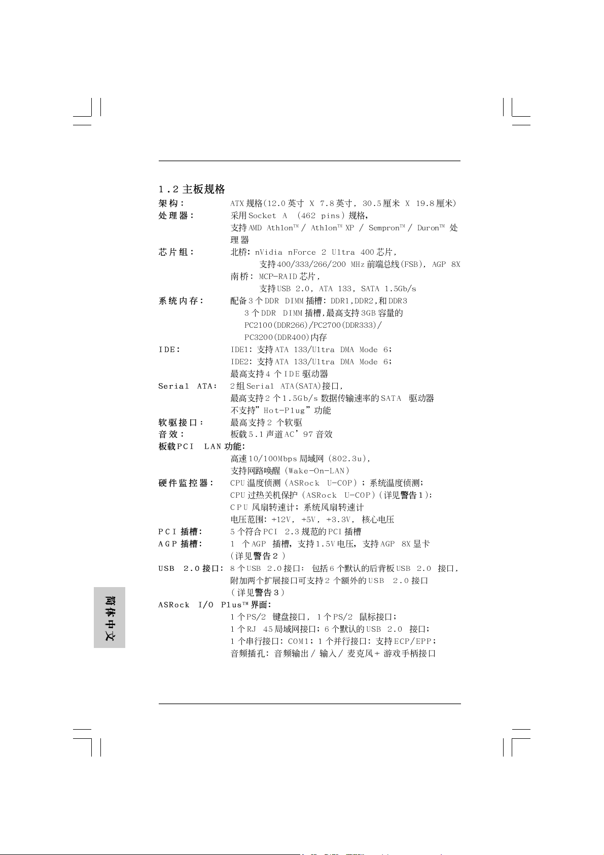
1.2 Specifications1.2 Specifications
1.2 Specifications
1.2 Specifications1.2 Specifications
Platform: ATX Form Factor (12.0-in x 7.8-in, 30.5-cm x 19.8-cm)
CPU: Supports Socket A (462 pins) for
AMD Athlon
Chipsets: North Bridge:
nVidia nForce 2 Ultra 400, FSB @ 400/333/266/200 MHz,
AGP 8X;
South Bridge:
MCP-RAID, supports USB 2.0, ATA 133, SATA 1.5Gb/s
Memory: 3 DDR DIMM slots: DDR1, DDR2, and DDR3
PC2100 (DDR266) / PC2700 (DDR333) / PC3200 (DDR400)
for 3 DDR DIMM slots, Max. 3GB;
IDE: IDE1: ATA 133 / Ultra DMA Mode 6;
IDE2: ATA 133 / Ultra DMA Mode 6;
Supports up to 4 IDE devices
Serial ATA: 2 SATA connectors,
support up to 2 SATA devices at1.5Gb/s data transfer rate
(Not Support “Hot Plug” function)
Floppy Port: Supports up to 2 floppy disk drives
Audio: 5.1 channels AC’97 Audio
LAN: Speed: 802.3u (10/100 Ethernet), supports Wake-On-LAN
Hardware Monitor: CPU temperature sensing;
Chassis temperature sensing;
CPU overheat shutdown to protect CPU life
(ASRock U-COP)(see CAUTION 1);
CPU fan tachometer; Chassis fan tachometer;
Voltage monitoring: +12V, +5V, +3.3V, Vcore
PCI slots: 5 slots with PCI Specification 2.3
AGP slot: 1 AGP slot, supports 1.5V, AGP 8X card (see CAUTION 2)
USB 2.0: 8 USB 2.0 ports:
includes 6 default USB 2.0 ports on the rear panel,
plus two headers to support 2 additional USB 2.0 ports
(see CAUTION 3)
ASRock I/O PlusTM: 1 PS/2 keyboard port, 1 PS/2 mouse port;
1 serial port: COM1;
1 parallel port: ECP/EPP support;
1 RJ 45 port;
6 default USB 2.0 ports;
Audio Jack: Line Out / Line In / Microphone
TM
/ Athlon
TM
XP / Sempron
TM
/ DuronTM processor
EnglishEnglish
EnglishEnglish
English
ASRock K7NF2-RAID Motherboard
55
5
55
Page 6
BIOS: AMI legal BIOS;
Supports “Plug and Play”;
ACPI 1.1 compliance wake up events;
SMBIOS 2.3.1 support;
CPU frequency stepless control
(only for advanced users’ reference, see CAUTION 4)
OS: Microsoft® Windows® 98 SE / ME / 2000 / XP compliant
CAUTION!
1. While CPU overheat is detected, the system will automatically shutdown.
Please check if the CPU fan on the motherboard functions properly before
you resume the system. To improve heat dissipation, remember to spray
thermal grease between the CPU and the heatsink when you install the PC
system.
2. Do NOT insert a 3.3V AGP card into the AGP slot of K7NF2-RAID
motherboard!It may cause permanent damage!
3. Power Management for USB 2.0 works fine under Microsoft® Windows
XP SP1/2000 SP4. It may not work properly under Microsoft® Windows
98/ME.
4. Although K7NF2-RAID offers stepless control, it is not recommended to
perform over clocking. Frequencies other than the recommended CPU bus
frequencies may cause the instability of the system or damage the CPU.
The CPU host frequency of this motherboard is determined by the jumpersetting. You must set the FSB jumper according to your AMD CPU before
you use the “Manual” option as the FSB setting in BIOS setup to perform
over clocking. Please che ck page 24 of “User Manual” in the Support CD for
details.
®
®
English
EnglishEnglish
EnglishEnglish
66
6
66
ASRock K7NF2-RAID Motherboard
Page 7
2. Installation2. Installation
2. Installation
2. Installation2. Installation
Pre-installation PrecautionsPre-installation Precautions
Pre-installation Precautions
Pre-installation PrecautionsPre-installation Precautions
Take note of the following precautions before you install motherboard
components or change any motherboard settings.
1. Unplug the power cord from the wall socket before touching any
component. Failure to do so may cause severe damage to the
motherboard, peripherals, and/or components.
2. To avoid damaging the motherboard components due to static electricity ,
NEVER place your motherboard directly on the carpet or the like. Also
remember to use a grounded wrist strap or touch a safety grounded
object before you handle components.
3. Hold components by the edges and do not touch the ICs.
4. Whenever you uninstall any component, place it on a grounded
antstatic pad or in the bag that comes with the component.
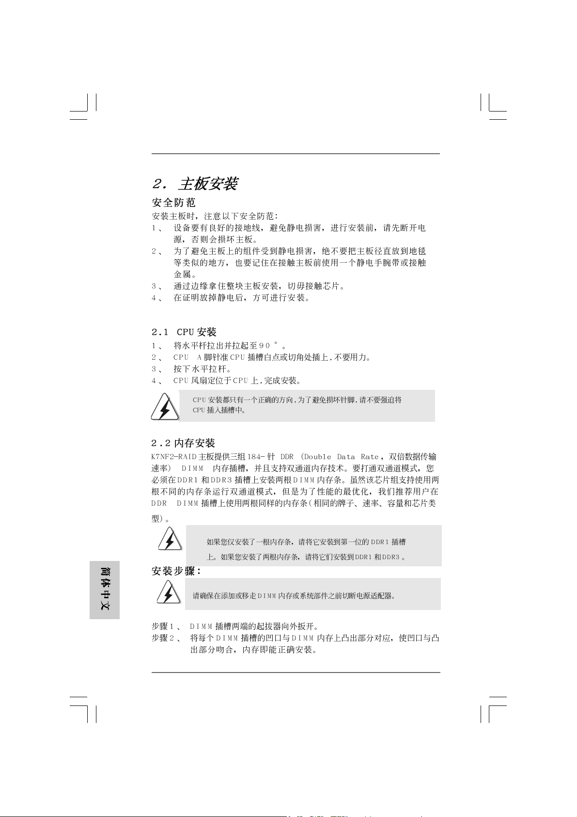
2.1 CPU Installation2.1 CPU Installation
2.1 CPU Installation
2.1 CPU Installation2.1 CPU Installation
STEP 1: Unlock the socket by lifting the lever up to a 90o angle.
STEP 2: Position the CPU directly above the socket such that its marked
corner matches the base of the socket lever.
STEP 3: Carefully insert the CPU into the socket until it fits in place.
The CPU fits only in one correct orientation. DO NOT force the CPU
into the socket to avoid bending of the pins.
STEP 4: When the CPU is in place, press it firmly on the socket while you
push down the socket lever to secure the CPU. The lever clicks on
the side tab to indicate that it is locked.
STEP 5: Install CPU fan and heatsink. For proper installation, please kindly
refer to the instruction manuals of your CPU fan and heatsink vendors.
ASRock K7NF2-RAID Motherboard
EnglishEnglish
EnglishEnglish
English
77
7
77
Page 8
2.22.2
Installation of Memory Modules (DIMM)Installation of Memory Modules (DIMM)
2.2
Installation of Memory Modules (DIMM)
2.22.2
Installation of Memory Modules (DIMM)Installation of Memory Modules (DIMM)
K7NF2-RAID motherboard provides three 184-pin DDR (Double Data Rate) DIMM slots,
and supports Dual Cha nnel Memory Technology. To enable Dual-Channel mode, you
need to install 2 DIMMs into DDR1 and DDR3 slots. Although this chipset ca n work on
the Dual-Channel mode with 2 different modules, we recommend users to use two
identical (the same brand, speed, size and chip-type) memory modules in the DDR
DIMM slots for optimized performance.
If you install only one memory module, please install it on DDR1 first.
If you install 2 memory modules, please install them on DDR1 and
DDR3.
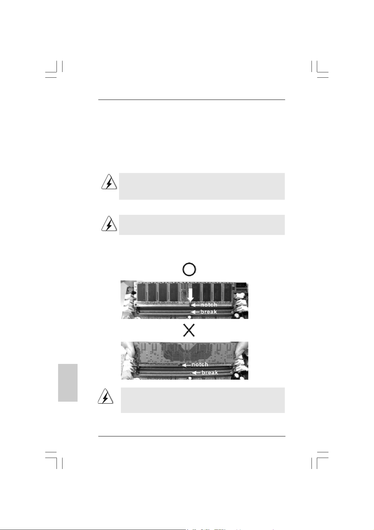
Installing a DIMMInstalling a DIMM
Installing a DIMM
Installing a DIMMInstalling a DIMM
Please make sure to disconnect power supply before adding or
removing DIMMs or the system components.
Step 1. Unlock a DIMM slot by pressing the retaining clips outward.
Step 2. Align a DIMM on the slot such that the notch on the DIMM matches the brea k
on the slot.
English
EnglishEnglish
EnglishEnglish
88
8
88
The DIMM only fits in one correct orientation. It will cause permanent
damage to the motherboard and the DIMM if you force the DIMM into
the slot at incorrect orientation.
Step 3. Firmly insert the DIMM into the slot until the retaining clips at both ends fully
snap back in place and the DIMM is properly seated.
ASRock K7NF2-RAID Motherboard
Page 9
2.3 Expansion Slots (PCI and AGP Slots)2.3 Expansion Slots (PCI and AGP Slots)
2.3 Expansion Slots (PCI and AGP Slots)
2.3 Expansion Slots (PCI and AGP Slots)2.3 Expansion Slots (PCI and AGP Slots)
There are 5 PCI slots and 1 AGP slot on K7NF2-RAID motherboard.
PCI slots: PCI slots are used to install expansion cards that have the 32-bit PCI
interface.
AGP slot: The AGP slot is used to install a graphics card.
The ASRock AGP slot has a special locking mechanism which can
securely fasten the graphics card inserted.
Please do NOT use a 3.3V AGP card on the AGP slot of K7NF2-RAID
motherboard! It may cause permanent damage! For the voltage
information of your VGA card, please check with the VGA card vendors.
Installing an expansion cardInstalling an expansion card
Installing an expansion card
Installing an expansion cardInstalling an expansion card
STEP 1: Before installing the expansion card, please make sure that the power
supply is switched off or the power cord is unplugged. Please read the
documentation of the expansion card and make necessary hardware
settings for the card before you start the installation.
STEP 2: Remove the bracket facing the slot that you intend to use. Keep the screws
for later use.
STEP 3: Align the card connector with the slot and press firmly until the card is
completely seated on the slot.
STEP 4: Fasten the card to the chassis with screws.
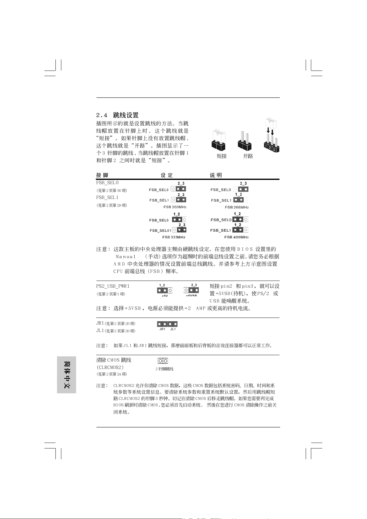
2.4 Jumpers Setup2.4 Jumpers Setup
2.4 Jumpers Setup
2.4 Jumpers Setup2.4 Jumpers Setup
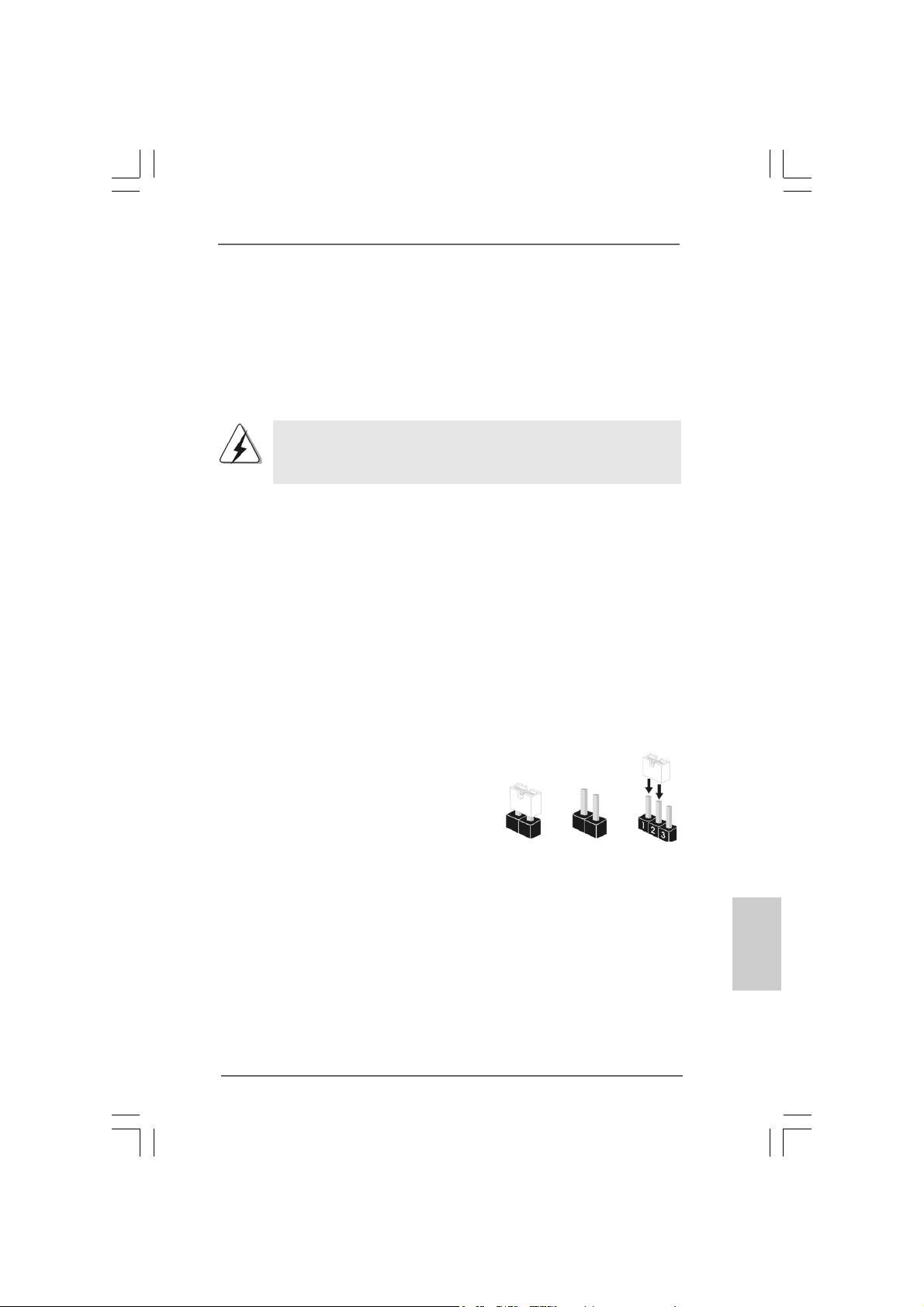
The illustration shows how jumpers are
setup. When the jumper cap is placed on
pins, the jumper is “Short”. If no jumper cap
is placed on pins, the jumper is “Open”. The
illustration shows a 3-pin jumper whose pin1
and pin2 are “Short” when jumper cap is
placed on these 2 pins.
Short
Open
ASRock K7NF2-RAID Motherboard
EnglishEnglish
EnglishEnglish
English
99
9
99
Page 10

Jumper Setting
FSB_SEL0
(see p.2 item 30)
FSB_SEL1
(see p.2 item 29)
Note: The setting of the CPU front side bus frequency of this motherboard is by means of the
adjustment of jumper-setting. You must set the FSB jumper according to your AMD CPU
before you use the “Manual” option as the FSB setting in BIOS setup to perform over
clocking. Please follow the figures above to set the CPU front side bus frequency.
PS2_USB_PWR1 Short pin2, pin3 to enable
(see p.2 item 1) +5VSB (standby) for PS/2
or USB wake up events.
Note: To select +5VSB, it requires 2 Amp and higher standby current provided by power supply.
JR1(see p.2 item 20)
JL1(see p.2 item 20)
Note: If the jumpers JL1 and JR1 are short, both the front panel and the rear panel audio
connectors will work.
English
EnglishEnglish
EnglishEnglish
1010
10
1010
Clear CMOS Jumper
(CLRCMOS2)
(see p.2 item 24)
Note: CLRCMOS2 allows you to clear the data in CMOS. The data in CMOS includes system
setup information such as system password, date, time, and system setup parameters. To
clear and reset the system parameters to default setup, please turn off the computer and
unplug the power cord from the power supply. After waiting for 15 seconds, use a jumper
cap to short 2 pins on CLRCMOS2 for 5 seconds. However, please do not clear the CMOS
right after you update the BIOS. If you need to clear the CMOS when you just finish
updating the BIOS, you must boot up the system first, and then shut it down before you
do the clear-CMOS action.
2-pin jumper
FID Jumpers
(FID0, FID1, FID2, FID3, FID4)
(see p.2 item 2)
Note: The set of FID jumpers are designed to adjust the multiplier of CPU. For detailed information,
please refer to page 15 of user Manual in the Support CD.
ASRock K7NF2-RAID Motherboard
Page 11

2.5 Connectors2.5 Connectors
2.5 Connectors
2.5 Connectors2.5 Connectors
Connectors are NOT jumpers. DO NOT place jumper caps over
these connectors. Placing jumper caps over the connectors will
cause permanent damage of the motherboard!
F DD Connector
(33-pin FLOPPY1)
(see p.2 item 18)
Note: Make sure the red-striped side of the cable is plugged into Pin1 side of the
connector.
Primary IDE Connector (Blue) Secondary IDE Connector (Black)
(39-pin IDE1, see p.2 item 11) (39-pin IDE2, see p.2 item 12)
the red-striped side to Pin1
connect the blue end
to the motherboard
80-conductor ATA 66/100/133 cable
Note: If you use only one IDE device on this motherboard, please set the IDE
device as “Master”. Please refer to the instruction of your IDE device
vendor for the details. Besides, to optimize compatibility and performance,
please connect your hard disk drive to the primary IDE connector (IDE1,
blue) and CD-ROM to the secondary IDE connector (IDE2, black).
Serial ATA Connectors These two Serial ATA (SATA)
(SATA1: see p.2 item 9) connectors support SATA data
(SATA2: see p.2 item 8) cables for internal storage
Serial A TA (SATA) Either end of the SATA data ca ble
Data Cable can be connected to the SATA
ASRock K7NF2-RAID Motherboard
SAT A2
SAT A1
connect the black end
to the IDE devices
devices. The current SATA
interface allows up to 1.5 Gb/s
data transfer rate.
hard disk or the SATA
connector on the motherboard.
1111
11
1111
EnglishEnglish
EnglishEnglish
English
Page 12
Serial ATA (SATA) Please connect the black end of
Power Cable SATA power cable to the power
(Optional) connector on each drive. Then
connect to the SAT A
HDD power connector
connect to the
power supply
connect the white end of SATA
power cable to the power
connector of the power supply.
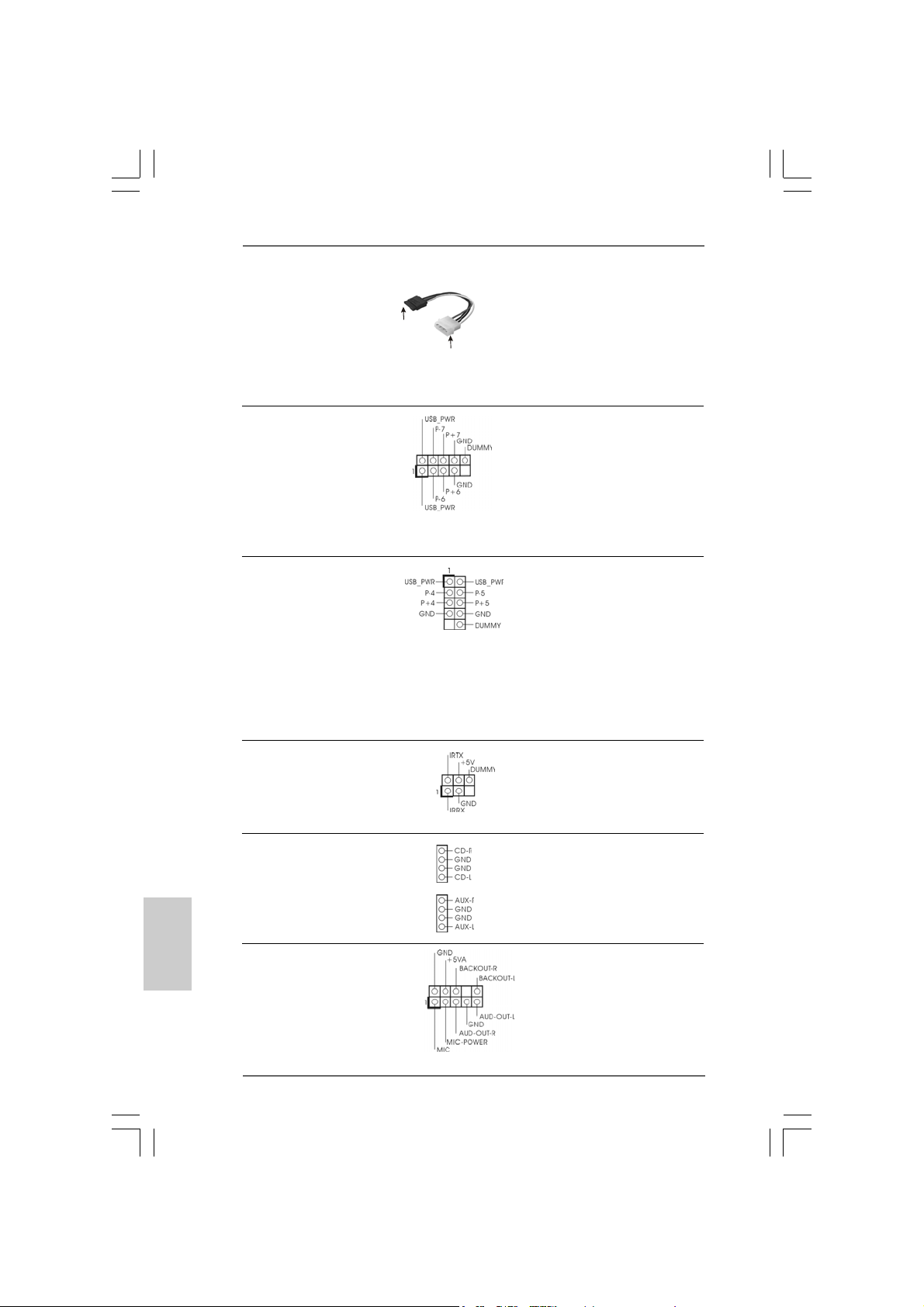
USB 2.0 Connector ASRock I/O PlusTM provides you
(9-pin USB67) 6 default USB 2.0 ports on the
(see p.2 item 17) rear panel. If the rear USB ports
are not sufficient, this USB 2.0
connector (USB67) is available
to support 2 additional USB 2.0
ports.
Shared USB 2.0 Connector This USB45 connector is shared
(9-pin USB45) with the USB 2.0 ports 4,5 on
(see p.2 item 28) the rear panel. When using the
front panel USB ports by
attaching the front panel USB
cable to this header (USB45),
the shared USB ports 4,5 on
the rear panel will not be able
to function.
English
EnglishEnglish
EnglishEnglish
1212
12
1212
Infrared Module Connector This connector supports an
(5-pin IR1) optional wireless transmitting
(see p.2 item 16) and receiving infrared module.
Internal Audio Connectors These connectors allow you to
(4-pin CD1, 4-pin AUX1) receive stereo audio input from
(CD1: see p.2 item 26) sound sources such as a
(AUX1: see p.2 item 25) CD-ROM, DV D-ROM, TV tuner
CD1
AUX1
card, or MPEG card.
Front Panel Audio Connector This is an interface for front
(9-pin AUDIO1) panel audio cable that allows
(see p.2 item 21) convenient connection and
control of audio devices.
ASRock K7NF2-RAID Motherboard
Page 13

System Panel Connector This connector accommodates
(9-pin PANEL1) several system front panel
(see p.2 item 14) functions.
Chassis Speaker Connector This connector allows you to
(4-pin SPEAKER 1) attach to the chassis speaker.
(see p.2 item 15)
Chassis Fan Connector Connect the fan cable to the
(3-pin CHA_FAN1) connector matching the black
(see p.2 item 13) wire to the ground pin.
CPU Fan Connector Connect the fan cable to the
(3-pin CPU_FAN1) connector matching the black
(see p.2 item 5) wire to the ground pin.
ATX Power Connector Connect an ATX power supply
(20-pin ATXPW R1) to the connector.
(see p.2 item 27)
Game Connector Connect a Game cable to this
(15-pin GAME1)
(see p.2 item 19) bracket is installed.
connector if the Game port
Game cable with the
Game port bracket
(Optional)
connect to the Ga me connector
ASRock K7NF2-RAID Motherboard
1313
13
1313
EnglishEnglish
EnglishEnglish
English
Page 14
English
EnglishEnglish
EnglishEnglish
2.62.6
Serial ASerial A
2.6
Serial A
2.62.6
Serial ASerial A
This motherboard supports Serial ATA (SATA) hard disks and RAID functions. This
section will guide you to install the SATA hard disks.
STEP 1: Install the SATA hard disks into the drive bays of your chassis.
STEP 2: Connect the SATA power cable to the SATA hard disk.
STEP 3: Connect one end of the SATA data cable to the motherboard’s SATA
connector.
STEP 4: Connect the other end of the SATA data cable to the SATA hard disk.
2.72.7
Installing Windows 2000 / Windows XP With RAIDInstalling Windows 2000 / Windows XP With RAID
2.7
Installing Windows 2000 / Windows XP With RAID
2.72.7
Installing Windows 2000 / Windows XP With RAIDInstalling Windows 2000 / Windows XP With RAID
FunctionsFunctions
Functions
FunctionsFunctions
If you want to install Windows 2000 or Windows XP on your SATA HDDs with RAID
functions, please follow the below steps.
STEP 1: Make a SATA Driver Diskette.
A. Insert the ASRock Support CD into your optical drive to boot your system.
B. During POST at the beginning of system boot-up, press <F11> key, and
then a window for boot devices selection appears. Please select CDROM as the boot device.
C. When you see the message on the screen, “Do you want to generate
Serial ATA driver diskette [YN]?”, press <Y>.
D. Then you will see these messages,
Please insert a floppy diskette into the floppy drive, and press <Y>.
E. The system will start to format the floppy diskette and copy SATA drivers
into the floppy diskette.
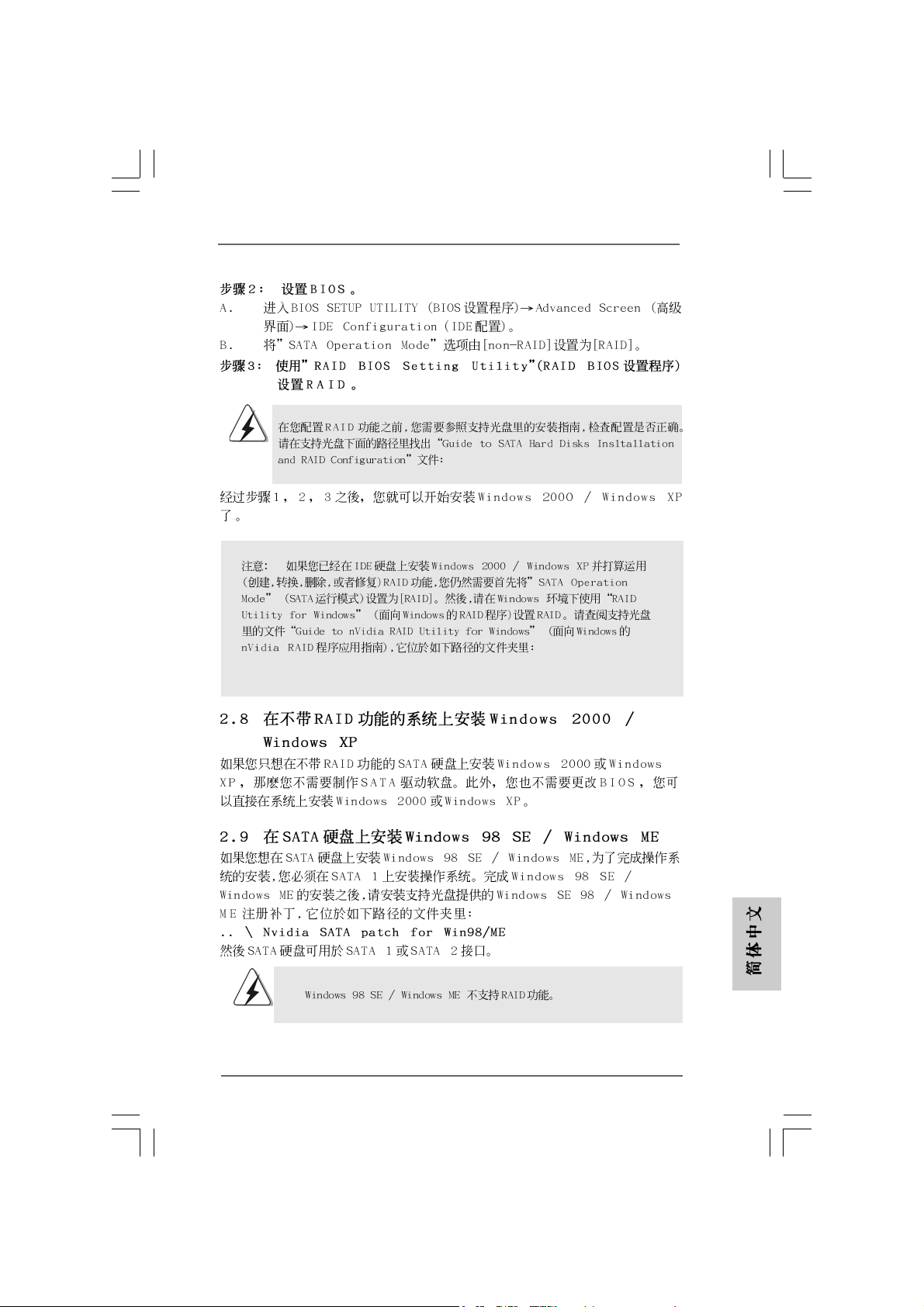
STEP 2: Set Up BIOS.
A. Enter BIOS SETUP UTILITY Advanced screen IDE Configuration.
B. Set the “SATA Operation Mode” option from [non-RAID] to [RAID].
STEP 3: Use “RAID BIOS Setting Utility” to set RAID configuration.
TT
A (SAA (SA
TT
T
TT
Please insert a diskette into the floppy drive.
WARNING! Formatting the floppy diskette will
lose ALL data in it!
Start to format and copy files [YN]?
A) Hard Disks InstallationA) Hard Disks Installation
A (SA
T
A) Hard Disks Installation
A (SAA (SA
TT
A) Hard Disks InstallationA) Hard Disks Installation
1414
14
1414
Before you start to configure the RAID function, you need to
check the installation guide in the Support CD for proper configuration.
Please refer to the document in the Support CD, “Guide to SATA Hard
Disks Installation and RAID Configuration”, which is located in the folder
at the following path:
.. \ RAID BIOS Setting Utility
ASRock K7NF2-RAID Motherboard
Page 15
After step1, 2, 3, you can start to install Windows 2000 / Windows XP.
NOTE. If you install Windows 2000 / Windows XP on IDE HDDs and want to manage
(create, convert, delete, or rebuild) RAID functions, you still need to set up
“SATA Operation Mode” to [RAID] first. Then, please set the RAID configura
-tion by using “RAID Utility for Windows” in Windows environment.
Please refer to the document in the Support CD, “Guide to nVidia RAID Utility
for Windows”, which is located in the folder at the following path:
.. \ RAID Utility for Windows
2.82.8
Installing Windows 2000 / Windows XP Without RAIDInstalling Windows 2000 / Windows XP Without RAID
2.8
Installing Windows 2000 / Windows XP Without RAID
2.82.8
Installing Windows 2000 / Windows XP Without RAIDInstalling Windows 2000 / Windows XP Without RAID
FunctionsFunctions
Functions
FunctionsFunctions
If you just want to install Windows 2000 or Windows XP on your SATA HDDs without
RAID functions, you don’t have to make a SATA driver diskette. Besides, there is no
need for you to change the BIOS setting. You can start to install Windows 2000 or
windows XP on your system directly.
2.92.9
Installing WInstalling W
2.9
Installing W
2.92.9
Installing WInstalling W
If you want to install Windows 98 SE / Windows ME on SATA HDD, it must be installed
on SATA 1 in order to f inish the OS in stallation process. After finishing the installation
of Windows 98 SE / Windows ME, please install Windows SE 98 / Windows ME
registry patch file provided in the support CD, which is located in the folder at the
following patch:
.. \ Nvidia SATA patch for Win98/ME
Then the SATA HDD can be used in SATA 1 or SATA 2 port.
indows 98 SE / Windows 98 SE / W
indows 98 SE / W
indows 98 SE / Windows 98 SE / W
indows ME on SAindows ME on SA
indows ME on SA
indows ME on SAindows ME on SA
TT
A HDDA HDD
T
A HDD
TT
A HDDA HDD
Windows 98 SE / Windows ME does not support RAID function.
ASRock K7NF2-RAID Motherboard
1515
15
1515
EnglishEnglish
EnglishEnglish
English
Page 16
3. BIOS Information3. BIOS Information
3. BIOS Information
3. BIOS Information3. BIOS Information
The Flash Memory on the motherboard stores BIOS Setup Utility. When you start up the
computer, please press <F2> during the Power-On-Self-Test (POST) to enter BIOS Setup utility;
otherwise, POST continues with its test routines. If you wish to enter BIOS Setup after POST,
please restart the system by pressing <Ctl> + <Alt> + <Delete>, or pressing the reset button on
the system chassis.
The BIOS Setup program is designed to be user-friendly. It is a menu-driven program, which allows
you to scroll through its various sub-menus and to select among the predetermined choices. For
the detailed information about BIOS Setup, please refer to the User Manual (PDF file) contained
in the Support CD.
English
EnglishEnglish
EnglishEnglish
4. Software Suppor4. Software Suppor
4. Software Suppor
4. Software Suppor4. Software Suppor
This motherboard supports various Microsoft® Windows® operating systems: 98 SE / ME / 2000
/ XP. The Support CD that came with the motherboard contains necessary drivers and useful
utilities that will enhance motherboard features.
To begin using the Support CD, insert the CD into your CD-ROM drive. It will display the Main
Menu automatically if “AUTORUN” is enabled in your computer. If the Main Menu does not appear
automatically, locate and double-click on the file “ASSETUP.EXE” from the BIN folder in the
Support CD to display the menus.
t CD informationt CD information
t CD information
t CD informationt CD information
1616
16
1616
ASRock K7NF2-RAID Motherboard
Page 17
ASRock K7NF2-RAID Motherboard
1717
17
1717
Page 18
1818
18
1818
ASRock K7NF2-RAID Motherboard
Page 19

” ”
®
®
ASRock K7NF2-RAID Motherboard
1919
19
1919
Page 20
2020
20
2020
ASRock K7NF2-RAID Motherboard
Page 21

ASRock K7NF2-RAID Motherboard
2121
21
2121
Page 22
2222
22
2222
” ”
ASRock K7NF2-RAID Motherboard
Page 23

“ ”
SAT A2
SAT A1
ASRock K7NF2-RAID Motherboard
2323
23
2323
Page 24

2424
24
2424
CD1
AUX1
ASRock K7NF2-RAID Motherboard
Page 25

ASRock K7NF2-RAID Motherboard
2525
25
2525
Page 26
2626
26
2626
ASRock K7NF2-RAID Motherboard
Page 27
.. \ RAID Utility for Windows
.. \ RAID BIOS Setting Utility
ASRock K7NF2-RAID Motherboard
2727
27
2727
Page 28

® ®
2828
28
2828
ASRock K7NF2-RAID Motherboard
Page 29

1. Einführung1. Einführung
1. Einführung
1. Einführung1. Einführung
Wir danken Ihnen für den Kauf des ASRock K7NF2-RAID Motherboard, ein
zuverlässiges Produkt, welches unter den ständigen, strengen Qualitätskontrollen
von ASRock gefertigt wurde. Es bietet Ihnen exzellente Leistung und robustes
Design, gemäß der Verpflichtung von ASRock zu Qualität und Halbarkeit. Dieses
Schnellstarthandbuch beinhaltet eine Einführung in das Motherboard, sowie eine
Schritt-für-Schritt-Installationsanweisung für Anfänger im Systembau.
Ausführlichere Informationen über das Motherboard finden Sie im Handbuch auf der
Support-CD.
Da sich Motherboard-Spezifikationen und BIOS-Software verändern können,
kann der Inhalt dieses Handbuches ebenfalls jederzeit geändert werden. Für
den Fall, dass sich Änderungen an diesem Handbuch ergeben, wird eine neue
Version auf der ASRock-Website, ohne weitere Ankündigung, verfügbar sein.
Die jeweils neueste Liste der unterstützten Speichertypen CPUs finden Sie
ebenfalls auf der Webseite von ASRock.
ASRock-Website: http://www.asrock.com
1.1 Kartoninhalt
ASRock K7NF2-RAID Motherboard
(ATX-Formfaktor: 30.5 cm x 19.8 cm; 12.0 Zoll x 7.8 Zoll)
ASRock K7NF2-RAID Schnellinstallationsanleitung
ASRock K7NF2-RAID Support-CD
Ein 80-adriges Ultra-ATA 66/100/133 IDE-Flachbandk abel
Ein Flachbandkabel für ein 3,5-Zoll-Diskettenlaufwerk
Ein serielle ATA- (SATA-) Datenkabel
Ein Seriell-ATA (SATA) Festplattennetzkabel (Option)
Ein ASRock I/O PlusTM Shield
Ein Game-Anschlusshalter (Option)
ASRock K7NF2-RAID Motherboard
2929
29
2929
DeutschDeutsch
DeutschDeutsch
Deutsch
Page 30

Deutsch
DeutschDeutsch
DeutschDeutsch
1.2 Spezifikationen
Plattform: ATX-Formfaktor: 30.5 cm x 19.8 cm (12.0 Zoll x 7.8 Zoll)
CPU: Unterstützt Sockel A (462 Pin) für AMD AMD Athlon
Athlon
TM
XP / Sempron
TM
/ Duron
TM
Prozessoren
Chipsatz: North Bridge:
nVidia nForce 2 Ultra 400, FSB @ 400/333/266/200
MHz, AGP 8X
South Bridge:
MCP-RAID, unterstützt USB 2.0, ATA 133,
SATA 1,5 Gb/s
RAM: 3 Steckplätze für DDR: DDR1, DDR2 und DDR3
PC2100 (DDR266) / PC2700 (DDR333) / PC3200
(DDR400) für 3 DD R DIMM Slots. Max. 3GB;
HDD: IDE1: AT A 133 / Ultra DMA Mode 6;
IDE2: ATA 133 / Ultra DMA Mode 6;
Unterstützt bis 4 IDE-Geräte
Seriell-ATA: 2 SATA-Anschlüsse, unterstützt bis zu 2 SATA-Geräte bei
einer Datenübertragungsrate von 1,5 Gb/s
(Unterstützt keine “Hot-Plug”-Funktionen)
Disk.lwk.anschl.: Unterstützt bis 2 Diskettenlaufwerke
Audio: 5.1 Kanal AC’97 Audio
LAN: Speed: 802.3u (10/100 Ethernet),
unterstützt Wake-On-LAN
Hardware Monitor: CPU Te mperaturmessung (ASRock U-COP);
Messung der häuseinnentemperatur;
CPU Shutdown bei Überhitzung, schützt die CPU vor dem
Hitzetod (ASRock U-COP)(siehe VORSICHT 1);
Rotationskontrolle für CPU-Lüfter;
Rotationskontrolle für Gehäuse-Lüfter;
Spannungsüberwachung: +12V, +5V, +3.3V, Vcore
PCI-Slots: 5 Slots nach PCI-Spezifikation 2.3
AGP-Slot : 1x AGP-Slot, unterstützt 1.5V, 8X AGP-Karten
(siehe VORSICHT 2)
USB 2.0: 8 USB 2.0-Anschlüsse:
einschließlich 6 Standard-USB 2.0-Anschlüsse auf der
Rückseite, plus einem Header zur Unterstützung 2
zusätzlicher USB 2.0-Anschlüsse (siehe VORSICHT 3)
TM
/
3030
30
3030
ASRock K7NF2-RAID Motherboard
Page 31

ASRock I/O PlusTM: 1 PS/2-Tastaturanschluss, 1 PS/2-Mausanschluss;
RJ 45; 6 Standard-USB 2.0-Anschlüsse;
1 serieller port: COM 1;
1 paralleler port: Unterstützung für ECP / EPP;
Audioanschlüsse: Line Out / Line In / Mikrofon + Gameport
BIOS: AMI legal BIOS mit Unterstützung für “Plug and Play”;
ACPI 1.1-Weckfunktionen;
JumperFree-Modus; SMBIOS 2.3.1;
Schrittloser CPU-Frequenz-Kontrolle (Nur für erfahrene
Anwender empfohlen, siehe VORSICHT 4)
Betriebssysteme: Unterstützt Microsoft® Windows® 98SE / ME / 2000 / XP
VORSICHT!
1. Wird eine Überhitzung der CPU registriert, führt das System einen
automatischen Shutdown durch. Bitte überprüfen Sie, ob der CPU-Lüfter
normal funktioniert, bevor Sie erneut starten. Um die Wärmeableitung
zu verbessern, bitte nicht vergessen, etwas Wärmeleitpaste zwischen
CPU und Kühlkörper zu sprühen.
2. Stecken Sie KEINE 3,3V AGP-Karte in der AGP-Steckplatz auf dem
K7NF2-RAID -Motherboard! Sie könnte einen irreparablen Schaden
verursachen!
3. Das Power Management für USB 2.0 arbeitet unter Microsoft® Windows
XP SP1/2000 SP4 einwandfrei. Unter Microsoft® Windows® 98/ME
könnte es dagegen zu Störungen kommen. .
4. Obwohl das K7NF2-RAID eine stufenlose Einstellung der Taktfrequenz
ermöglicht, ist es nicht empfehlenswert, das System zu übertakten.
Frequenzen, die über den für den jeweiligen Prozessor
vorgesehenen liegen, können das System instabil werden lassen oder
die CPU beschädigen. Die CPU-Host-Frequenz dieses Motherboards
wird von der Jumper-Einstellung bestimmt. Sie müssen den FSBJumper gemäß Ihrer AMD-CPU setzen, bevor Sie mit der Option
“Manual” (Manuell) im BIOS-Setup Overclocking als FSB-Einstellung
vornehmen. Details sind im Handbuch auf Seite 24 auf der Support-CD
angegeben.
®
ASRock K7NF2-RAID Motherboard
3131
31
3131
DeutschDeutsch
DeutschDeutsch
Deutsch
Page 32

2. Installation
Sicherheitshinweise vor der Montage
Bitte nehmen Sie die folgende Sicherheitshinweise zur Kenntnis, bevor Sie das
Motherboard einbauen oder Veränderungen an den Einstellungen vornehmen.
1. Trennen Sie das System vom Stromnetz, bevor Sie eine Systemkomponente
berühren, da es sonst zu schweren Schäden am Motherboard oder den
sonstigen internen, bzw. externen Komponenten kommen kann.
2. Um Schäden aufgrund von statischer Elektrizität zu vermeiden, das
Motherboard NIEMALS auf einen Teppich o.ä.legen. Denken Sie außerem
daran, immer ein geerdetes Armband zu tragen oder ein geerdetes Objekt
aus Metall zu berühren, bevor Sie mit Systemkomponenten hantieren.
3. Halten Sie Komponenten immer an den Rändern und vermeiden Sie
Berührungen mit den ICs.
4. Wenn Sie Komponenten ausbauen, legen Sie sie immer auf eine antistatische
Unterlage, oder zurück in die Tüte, mit der die Komponente geliefert wurde.
2.1 CPU Installation
Schritt 1: Öffnen Sie den CPU-Sockel, indem sie den Hebel leicht zur Seite und
dann nach oben ziehen, auf einen Winkel von 90°.
Schritt 2: Halten Sie die CPU korrekt ausgerichtet über den Sockel, so dass die
markierte Ecke der CPU zum Hebelgelenk zeigt.
Schritt 3: Drücken Sie die CPU vorsichtig in den Sockel.
Deutsch
DeutschDeutsch
DeutschDeutsch
3232
32
3232
Die CPU sollte problemlos in den Sockel passen. Drücken Sie die CPU
nicht mit Gewalt in den Sockel, damit sich die Pins nicht verbiegen.
Überprüfen Sie die Ausrichtung und suchen nach verbogenen Pins,
sollte die CPU nicht in den Sockel passen.
Schritt 4: Wenn die CPU korrekt im Sockel sitzt, leicht mit de m Finger
draufdrücken und gleichzeitig den Hebel nach unten drücken, bis er
hörbar einrastet.
Schritt 5: Installieren Sie einen aktiven CPU-Kühler, der die gesamte Fläche der
CPU abdeckt und eine ausreichende Wärmeableitung für den von
Ihnen verwendeten CPU-Typ bietet. Weitere Hinweise finden Sie der
Installationsanleitung für Ihren CPU-Kühler.
ASRock K7NF2-RAID Motherboard
Page 33

2.2 Installation der Speichermodule (DIMM)2.2 Installation der Speichermodule (DIMM)
2.2 Installation der Speichermodule (DIMM)
2.2 Installation der Speichermodule (DIMM)2.2 Installation der Speichermodule (DIMM)
Das K7NF2-RAID Motherboard bietet drei 184-polige DDR (Double Data Rate) DIMMSteckplätze und unterstützt die Doppelkanal-Speichertechnologie. Um den
Doppelkanalmodus zu aktivieren, müssen Sie zwei DIMMs in den Steckplätzen
DDR1 und DDR3 in stallieren. Obwohl die se s Chipset den Doppelka nalmodus mit
zwei verschiedenen Modulen unterstützt, empfehlen wir für optimale Leistung die
Verwendung zweier identischer Speichermodule (selbe Marke, Geschwindigkeit,
Größe und selber Chiptyp) in den DD R DIMM-Steckplätzen.
Falls Sie nur ein Speichermodul installieren, verwenden Sie bitte zuerst
Steckplatz DDR1. Falls Sie zwei Speichermodule installieren, verwenden Sie
bitte die Steckplätze DDR1 und DDR3.
Einsetzen eines DIMM-ModulsEinsetzen eines DIMM-Moduls
Einsetzen eines DIMM-Moduls
Einsetzen eines DIMM-ModulsEinsetzen eines DIMM-Moduls
Achten Sie darauf, das Netzteil abzustecken, bevor Sie DIMMs oder
Systemkomponenten hinzufügen oder entfernen.
Schritt 1: Öffnen Sie einen DIMM-Slot, indem Sie die seitlichen Clips nach außen
drücken.
Schritt 2: Richten Sie das DIMM-Modul so über dem Slot aus, dass das Modul mit
der Kerbe in den Slot passt.
Die DIMM-Module passen nur richtig herum eingelegt in die
Steckplätze. Falls Sie versuchen, die DIMM-Module mit Gewalt falsch
herum in die Steckplätze zu zwingen, führt dies zu dauerhaften
Schäden am Mainboard und am DIMM-Modul.
Schritt 3: Drücken Sie die DIMM-Module fest in die Steckplätze, so dass die
Halteklammern an beiden Enden des Moduls einschnappen und das
DIMM-Modul fest an Ort und Stelle sitzt.
ASRock K7NF2-RAID Motherboard
3333
33
3333
DeutschDeutsch
DeutschDeutsch
Deutsch
Page 34

2.3 Erweiterungssteckplätze (PCI und AGP-Slots):
Es stehen 5 PCI- und 1 AGP-Slot auf dem K7NF2-RAID - Motherboard zur
Verfügung.
PCI-Slots: PCI-Slots werden zur Installation von Erweiterungskarten mit dem
32bit PCI-Interface genutzt.
AGP-Slot: Der AGP-Slot wird zur Installation einer Gfrafikkarte genutzt.
Der ASRock AGP-Slot besitzt einen speziellen
Verschlussmechanismus, der die eingesetzte Karte sicher
festhält.
Stecken Sie KEINE 3,3V AGP-Karte in der AGP-Steckplatz auf
dem K7NF2-RAID -Motherboard! Sie könnte einen irreparablen
Schadenverursachen! Erkundigen Sie sich beim Verkäufer der
Grafikkarte nach den Spannungsdaten für Ihre Grafikkarte.
Einbau einer Erweiterungskarte
Schritt 1: Bevor Sie die Erweiterungskarte installieren, vergewissern Sie sich,
dass das Netzteil ausgeschaltet und das Netzkabel abgezogen ist.
Bitte lesen Sie die Dokumentation zur Erweiterungskarte und nehmen
Sie nötige Hardware-Einstellungen für die Karte vor, ehe Sie mit der
Installation beginnen.
Schritt 2: Entfernen Sie das Abdeckungsblech (Slotblende) von dem
Gehäuseschacht (Slot) , den Sie nutzen möchten und behalten die
Schraube für den Einbau der Karte.
Schritt 3: Richten Sie die Karte über dem Slot aus und drücken Sie sie ohne
Gewalt hinein, bis sie den Steckplatz korrekt ausfüllt.
Schritt 4: Befestigen Sie die Karte mit der Schraube aus Schritt 2.
Deutsch
DeutschDeutsch
DeutschDeutsch
3434
34
3434
ASRock K7NF2-RAID Motherboard
Page 35

2.4 Einstellung der Jumper
Die Abbildung verdeutlicht, wie Jumper
gesetzt werden. Werden Pins durch
Jumperkappen verdeckt, ist der Jumper
“Gebrückt”. Werden keine Pins durch
Jumperkappen verdeckt, ist der Jumper
“Offen”. Die Abbildung zeigt einen 3-Pin
Jumper dessen Pin1 und Pin2 “Gebrückt”
sind, bzw. es befindet sich eine JumperKappe auf diesen beiden Pins.
Jumper Einstellun Beschreibung
FSB_SEL0
(siehe S.2, Punkt 30)
FSB_SEL1
(siehe S.2, Punkt 29)
Hinweis: Die CPU-Host-Frequenz dieses Motherboards wird von der Jumper-
Einstellung bestimmt. Sie müssen den FSB-Jumper gemäß Ihrer AMDCPU setzen, bevor Sie mit der Option “Manual” (Manuell) im BIOS-Setup
Overclocking als FSB-Einstellung vornehmen. Folgen Sie den
Abbildungen, um die “Front Side Bus”-Frequenz einzustellen.
Gebrückt Offen
PS2_USB_PWR1 Zum Aktivieren von +5VSB
(siehe S.2 - Punkt 1) (standby) für PS/2 USB wake
up events, Pin2 und Pin3
brücken.
Hinweis: Um +5VSB nutzen zu können, wird ein Netzteil benötigt, welches auf
dieser Leitung 2A liefern kann.
JR1(siehe S.2 - Punkt 20)
JL1 (siehe S.2 - Punkt 20)
Hinweis: Sind die Jumper JL1 und JR1 gesetzt funktionieren beide
Audioanschlüsse, Front- und Rückseite.
ASRock K7NF2-RAID Motherboard
3535
35
3535
DeutschDeutsch
DeutschDeutsch
Deutsch
Page 36

CMOS löschen Jumper
(CLRCMOS2)
(siehe S.2 - Punkt 24)
Hinweis: CLRCMOS2 erlaubt Ihnen da s Löschen der CMOS-Daten. Diese
beinhalten das System-Passwort, Datum, Zeit und die verschiedenen
BIOS-Parameter. Um die Systemparameter zu löschen und auf die
Werkseinstellung zurückzusetzen, schalten Sie bitte den Computer ab
und entfernen das Stromkabel. Benutzen Sie eine Jumperkappe, um die
Pins an CLRCMOS2 für 3 Sekunden kurzzuschließen. Bitte vergessen
Sie nicht, den Jumper wieder zu entfernen, nachdem das CMOS
gelöscht wurde. Wenn Sie den CMOS-Inhalt gleich nach dem
Aktualisieren des BIOS löschen müssen, müssen Sie zuerst das System
starten und dann wieder ausschalten, bevor Sie den CMOS-Inhalt
löschen.
FID Jumpers
(FID0, FID1, FID2, FID3, FID4)
(siehe S.2, Punkt 2)
Hinweis: Das Set mit FID-Jumpern dient zum Einstellen der Multiplier der CPU. Details
sind im Handbuch auf Seite 15 auf der Support-CD angegeben.
2-pin jumper
Deutsch
DeutschDeutsch
DeutschDeutsch
3636
36
3636
ASRock K7NF2-RAID Motherboard
Page 37

2.5 Anschlüsse
Anschlussleisten sind KEINE Jumper. Setzen Sie KEINE Jumperkappen
auf die Pins der Anschlussleisten. Wenn Sie die Jumperkappen auf die
Anschlüsse setzen, wird das Motherboard permanent beschädigt!
Anschluss Beschreibung
Anschluss für das
Floppy-Laufwerk
(33-Pin FLOPPY1)
(siehe S.2 - Punkt 18)
Hinweis: Achten Sie darauf, dass die rotgestreifte Seite des Kabel mit der Stift 1-
Seite des Anschlusses verbunden wird.
Primärer IDE-Anschluss (blau) Sekundärer IDE-Anschluss (schwarz)
(39-pin IDE1, siehe S.2 - Punkt 11) (39-pin IDE2, siehe S.2 - Punkt 12)
Blauer Anschluss Schwarzer Anschluss
zum Motherboard zur Festplatte
80-adriges A TA 66/100/133-Kabel
Hinweis: Wenn Sie auf diesem Motherboard nur ein IDE-Gerät einsetzen, richten Sie
das IDE-Gerät als “Master” ein. Details entnehmen Sie bitte den
Anweisungen Ihres IDE-Gerätehändlers. Zur Optimierung der Kompatibilität
und Leistung verbinden Sie die Festplatte mit dem primären IDE-Anschluss
(IDE1, blau) und das CD-ROM mit de m sekundären IDE-Anschluss (IDE2,
schwarz).
die rotgestreifte Seite auf Stift 1
Seriell-ATA-Anschlüsse Diese beiden Serial ATA- (SATA-)
(SAT A1: siehe S.2 - Punkt 9) Verbínder unterstützten SATA-
(SAT A2: siehe S.2 - Punkt 8) Datenkabel für interne
SAT A2
Massenspeichergeräte. Die
SAT A1
aktuelle SATA-Schnittstelle
ermöglicht eine
Datenübertragungsrate bis 1,5 Gb/s.
ASRock K7NF2-RAID Motherboard
3737
37
3737
DeutschDeutsch
DeutschDeutsch
Deutsch
Page 38

Serial ATA- (SATA-) Sie können beide Enden des
Datenkabel SATA-Datenkabels entweder mit
der SATA-Festplatte oder dem
SATA-Anschluss am Mainboard
verbinden.
Serial A TA- (SATA-) Verbinden Sie bitte das
Stromversorgungskabel schwarze Ende des SATA-
(Option) Stromversorgungskabels mit
SATA-HDD-Stromanschluss
Verbindung zum
Verbindung zum
Netzteil
dem Stromanschluss jedes
Laufwerks. Verbinden Sie dann
das weiße Ende des SATAStromversorgungskabels mit
dem Stromanschluss des
Netzteils.
USB 2.0-Anschluss ASRock I/O Plus™ verfügt über 6
(9-pin USB67) Standard-USB 2.0-Anschlüsse
(siehe S.2 - Punkt 17) auf der Rückseite. Wenn die
hinteren USB-Anschlüsse nicht
ausreichen, steht dieser USB 2.
0-Anschluss (USB67) zur
Unterstützung 2 weiterer USB 2.
0-Anschlüsse zur Verfügung.
Deutsch
DeutschDeutsch
DeutschDeutsch
3838
38
3838
Gemeinsam verwendeter Dieser USB45-Anschluss wird
USB 2.0-Anschluss mit dem USB 2.0-Anschlüssen 4,
(9-pin USB45) 5 auf dem ASRock I/O Plus™
(siehe S.2 - Punkt 28) gemeinsam verwendet. Werden
die USB-Anschlüsse auf der
Vorderseite durch Verbindung
des vorderseitigen USB-Kabels
mit diesem Anschluss (USB45)
verwendet, werden die USBAnschlüsse 4,5 auf dem ASRock
I/O Plus™ nicht funktionieren
können.
ASRock K7NF2-RAID Motherboard
Page 39

Anschluss für Dieser Anschluss unterstützt
Infrarot-Modul einen optionalen Infrarot-
(5-Pin IR1) Sender/Empfänger.
(siehe S.2 - Punkt 16)
Interne Audio-Anschlüsse Diese ermöglichen Ihnen
(4-Pin CD1, 4-Pin AUX1) Stereo-Signalquellen, wie z. B.
(CD1: siehe S.2 - Punkt 26) CD-ROM, DV D-ROM, TV-T uner
(AUX1: siehe S.2 - Punkt 25) oder MPEG-Karten mit Ihrem
CD1
AUX1
System zu verbinden.
Anschluss für Audio auf Dieses Interface zu einem
der Gehäusevorderseite Audio-Panel auf der Vorderseite
(9-Pin AUDIO1) Ihres Gehäuse s, ermöglicht
(siehe S.2 - Punkt 21) Ihnen eine bequeme
Anschlussmöglichkeit und
Kontrolle über Audio-Geräte.
System Panel Anschluss Dieser Anschluss ist für die
(9-Pin PANEL1) verschiedenen Funktionen der
(siehe S.2 - Punkt 14) Gehäusefront.
Lautsprecheranschluss Dieser Anschluss ermöglicht die
(4-pin SPEAKER1) Nutzung eines PC-Speakers.
(siehe S.2 - Punkt 15)
Anschluss für Gehäuselüfter Verbinden Sie das Lüfterkabel
(3-pin CHA_FAN1) so, dass der Massepin der
(siehe S.2 - Punkt 13) Anschlussbuchse mit dem
schwarzen Lüfterkabel
übereinstimmt.
Anschluss für CPU-Lüfter Verbinden Sie das Lüfterkabel
(3-pin CPU_FAN1) so, dass der Massepin der
(siehe S.2 - Punkt 5) Anschlussbuchse mit dem
schwarzen Lüfterkabel
übereinstimmt.
ASRock K7NF2-RAID Motherboard
3939
39
3939
DeutschDeutsch
DeutschDeutsch
Deutsch
Page 40

Anschluss für ATX-Netzteil Dieser 20Pin-Anschluss ist zur
(20-pin ATXPW R1) Verwendung eines ATX 12V-
(siehe S.2 - Punkt 27) Netzteils gedacht.
Game-Anschluss Verbinden Sie ein Game-Kabel mit
(15-pin GAME1) diesem Anschluss, wenn der
(siehe S.2 - Punkt 19) Game-Anschlusshalter installiert
ist.
Game port-Kabel mit
Gameport-Blech
(Option)
Verbindung zum Gameport-An schluss
Deutsch
DeutschDeutsch
DeutschDeutsch
4040
40
4040
Serial ASerial A
2.6
Serial A
Serial ASerial A
Dieses Mainboard arbeitet mit dem MCP-RAID Southbridge-Chipsatz, der Serial AT A (SATA-) Festplatten unterstützt. Als lokale Datenspeichergeräte können Sie SATALaufwerke an dieses Mainboard anschließen. Dieser Abschnitt zeigt Ihnen, wie Sie
die SATA-Festplatten installieren.
TT
AA
T
A
TT
AA
- (SA- (SA
- (SA
- (SA- (SA
TT
A) FA) F
estplatteninstallationestplatteninstallation
T
A) F
estplatteninstallation
TT
A) FA) F
estplatteninstallationestplatteninstallation
SA TA-Fe stplatten installieren
SCHRITT 1: Installieren Sie die SATA-Festplatten in den Laufwerkseinschüben
des Gehäuses.
SCHRITT 2: Verbinden Sie ein Ende des SATA-Datenkabels mit dem primären
SATA-Anschluss (SATA1) des Mainboards.
SCHRITT 3: Verbinden Sie das andere Ende des SATA-Datenkabels mit der
primären SATA-Festplatte.
SCHRITT 4: Verbinden Sie ein Ende des zweiten SATA-Datenkabels mit dem
sekundären SATA-Anschluss (SATA2) des Mainboards.
SCHRITT 5: Verbinden Sie das andere Ende des SATA-Datenkabels mit der
sekundären SATA-Festplatte.
ASRock K7NF2-RAID Motherboard
Page 41

Installation von Windows 2000 / Windows XP mit RAID-Installation von Windows 2000 / Windows XP mit RAID-
2.7
Installation von Windows 2000 / Windows XP mit RAID-
Installation von Windows 2000 / Windows XP mit RAID-Installation von Windows 2000 / Windows XP mit RAID-
Funktionen Funktionen
Funktionen
Funktionen Funktionen
Bitte gehen Sie wie folgt vor, wenn Sie Windows 2000 oder Windows XP auf
Ihren SATA-Festplatten mit RAID-Funktionen installieren möchten.
SCHRITT 1: Erstellen Sie eine SATA-Treiberdiskette.
A. Legen Sie die ASRock Support-CD in Ihr optisches Laufwerk, um Ihr System
hochzufahren. (Legen Sie zu diesem Zeitpunkt KEINE Diskette in das
Diskettenlaufwerk ein!)
B. Während des Selbsttests zu Beginn des Systemstarts drücken Sie die <F11>-
Taste – ein Fenster zur Auswahl des Boot-Laufwerkes (Startlaufwerk)
erscheint. Bitte wählen Sie das CD-ROM-Laufwerk als Boot-Laufwerk.
C. Die Meldung „Do you want to generate Serial ATA driver diskette [Y/N]?“
[Serial ATA-Treiberdiskette erstellen [Y/N]?] bestätigen Sie mit <Y>.
D. Daraufhin werden die Meldungen
Please insert a diskette into the floppy drive.
WARNING! Formatting the floppy diskette will
lose ALL data in it!
Start to format and copy files [Y/N]?
[Bitte legen Sie eine Diskette in das Diskettenlaufwerk
ein. WARNUNG! Das Formatieren der Diskette löscht
ALLE darauf enthaltenen Daten!
Formatieren und Kopieren der Dateien starten [Y/N]?]
angezeigt. Legen Sie bitte eine Diskette in das
Diskettenlaufwerk ein und drücken Sie <Y>.
E. Das System beginnt mit dem Formatieren der Dis kette und kopiert die SATA-
Treiber auf die Diskette.
SCHRITT 2: Konfigurieren Sie BIOS.
A. Rufen Sie im BIOS-DIENSTPROGRAMM den Bildschirm „Erweitert“ und
„IDE-Konfiguration“ auf.
B. Stellen Sie die Option “SAT A-Betriebsmodus” von [nicht-RAID] auf [RAID] um.
SCHRITT 3: Verwenden Sie das “RAID BIOS Konfigurationsprogramm”, um
die RAID-Konfiguration einzustellen.
Vor der Installation der SATA-Festplatten und der Konfiguration der
RAID-Funktion müssen Sie sich in der Installationsanleitung auf der
Support-CD über die richtige Installation und Konfiguration
informieren. Sie finden das Dokument, “Guide to SATA Hard Disks
Installation and RAID Configuration” unter folgendem Pfad auf der
Support-CD:
.. \ RAID BIOS Setting Utility
ASRock K7NF2-RAID Motherboard
4141
41
4141
DeutschDeutsch
DeutschDeutsch
Deutsch
Page 42

Nach den Schritten 1, 2 und 3 können Sie mit der Installation von Windows 2000 /
Windows XP beginnen.
HINWEIS: Wenn Sie Windows 2000 / Windows XP auf IDE-Festplatten installieren
und RAID-Funktionen verwalten möchten (erstellen, umwandeln,
löschen oder aufbauen), müssen Sie dennoch zuvor die Option “RAID Betriebsmodus” auf [RAID] einstellen. Stellen Sie danach bitte die RAID Konfiguration mithilfe des ”RAID-Programms für Windows” in der
Windows-Umgebung ein. Bitte lesen Sie hierzu das Dokument ”Anleitung
für nVidia RAID-Programm für Windows”, das sich auf dem folgenden
Pfad der mitgelieferten CD befindet:
.. \ RAID Utility for Windows
2.8 Installation von Windows 2000 / Windows XP ohne RAID Funktionen
Wenn Sie auf Ihren SATA-Festplatten lediglich Windows 2000 oder Windows XP
ohne RAID-Funktionen installieren möchten, ist das Anlegen einer SATATreiberdiskette nicht erforderlich. Außerdem brauchen Sie die BIOS-Einstellungen
nicht zu ändern. Sie können Windows 2000 oder Windows XP direkt auf Ihr
System installieren.
2.92.9
Installation von Windows 98 SE / Windows MEInstallation von Windows 98 SE / Windows ME
2.9
Installation von Windows 98 SE / Windows ME
2.92.9
Installation von Windows 98 SE / Windows MEInstallation von Windows 98 SE / Windows ME
auf einer SAauf einer SA
auf einer SA
auf einer SAauf einer SA
Wenn Sie Windows 98 SE / Windows ME auf einer SATA-Festplatte installieren
möchten, muss die Installation auf SATA 1 erfolgen, um den Installationsvorgang
des Betriebssystems abschließen zu können. Nach der Installation von Windows
98 SE / Windows ME installieren Sie bitte die Registry-Patchdatei für Windows SE
98 / Windows ME, die sich auf der mitgelieferten Support-CD im folgenden
Verzeichnis befindet:
..\ Nvidia SATA patch for Win98/ME
Danach kann die SATA-Festplatte mit SATA 1 oder SATA 2 verwendet werden.
TT
AA
-F-F
T
A
-F
TT
AA
-F-F
estplatteestplatte
estplatte
estplatteestplatte
Deutsch
DeutschDeutsch
DeutschDeutsch
4242
42
4242
Windows 98 SE / Windows ME unterstützt keine “RAID” -Funktionen.
ASRock K7NF2-RAID Motherboard
Page 43

3. BIOS-Information3. BIOS-Information
3. BIOS-Information
3. BIOS-Information3. BIOS-Information
Das Flash Memory dieses Motherboards speichert das Setup-Utility. Drücken Sie <F2> während
des POST (Power-On-Self-Test) um ins Setup zu gelangen, ansonsten werden die Testroutinen
weiter abgearbeitet. Wenn Sie ins Setup gelangen wollen, na chde m der POST durchgeführt wurde,
müssen Sie das System über die Tastenkombination <Ctrl> + <Alt> + <Delete> oder den ResetKnopf auf der Gehäusevorderseite, neu starten. Natürlich können Sie einen Neustart auch
durchführen, indem Sie das System kurz ab- und danach wieder anschalten.
Das Setup-Programm ist für eine bequeme Bedienung entwickelt worden. Es ist ein
menügesteuertes Programm, in dem Sie durch unterschiedliche Untermenüs scrollen und die
vorab festgelegten Optionen auswählen können. Für detaillierte Informationen zum BIOSSetup, siehe bitte das Benutzerhandbuch (PDF Datei) auf der Support CD.
4. Software Suppor4. Software Suppor
4. Software Suppor
4. Software Suppor4. Software Suppor
Dieses Motherboard unterstützt eine Reiche von Microsoft Windows Betriebssystemen: 98 SE
/ ME / 2000 / XP. Die Ihrem Motherboard beigefügte Support-CD enthält hilfreiche Software,
Treiber und Hilfsprogramme, mit denen Sie die Funktionen Ihres Motherboards verbessern
können Legen Sie die Support-CD zunächst in Ihr CD-ROM-Laufwerk ein. Der
Willkommensbildschirm mit den Installationsmenüs der CD wird automatisch aufgerufen, wenn
Sie die “Autorun”-Funktion Ihres Systems aktiviert haben.
Erscheint der Wilkommensbildschirm nicht, so “doppelklicken” Sie bitte auf das File ASSETUP.
EXE im BIN-Verzeichnis der Support-CD, um die Menüs aufzurufen.
Das Setup-Programm soll es Ihnen so leicht wie möglich machen. Es ist menügesteuert, d.h. Sie
können in den verschiedenen Untermenüs Ihre Auswa hl treffen und die Programme werden da nn
automatisch installiert.
t CD informationt CD information
t CD information
t CD informationt CD information
DeutschDeutsch
DeutschDeutsch
Deutsch
ASRock K7NF2-RAID Motherboard
4343
43
4343
Page 44

1. Introduction1. Introduction
1. Introduction
1. Introduction1. Introduction
Merci pour votre achat d’une carte mère ASRock K7NF2-RAID, une carte mère très
fiable produite selon les critères de qualité rigoureux de ASRock. Elle offre des
performances excellentes et une conception robuste conformément à l’engagement
d’ASRock sur la qualité et la fiabilité au long terme.
Ce Guide d’installation rapide intègre une présentation de la carte mère et un guide
d’installation étape par étape à l’attention de ceux qui assemblent eux-mêmes leur
système. Des informations plus détaillées sur la carte mère sont fournies dans le
manuel utilisateur sur le CD de support.
Les spécifications de la carte mère et le BIOS ayant pu être mis à jour,
le contenu de ce manuel est sujet à des changements sans notification.
Au cas où n’importe qu’elle modification intervenait sur ce manuel, la
version mise à jour serait disponible sur le site web ASRock sans
nouvel avis. Vous pouvez également trouver la dernière liste des
mémoires et microprocesseurs pris en charge sur le site web d’ASRock.
Site web ASRock, http://www.asrock.com
1.1 Contenu du paquet
Carte mère ASRock K7NF2-RAID
(Facteur de forme ATX : 12.0 pouces x 7.8 pouces, 30.5 cm x 19.8 cm)
Guide d’installation rapide ASRock K7NF2-RAID
CD de soutien ASRock K7NF2-RAID
Un câble ruban IDE Ultra ATA 66/100/133 80 conducteurs
Un câble ruban pour un lecteur de disquettes 3,5 pouces
Un câbles de données série ATA (SATA)
Un cordon d’alimentation DD série ATA (SATA) (en option)
Un écra n ASRock I/O Plus
Un support port jeux (en option)
TM
Français
FrançaisFrançais
FrançaisFrançais
4444
44
4444
ASRock K7NF2-RAID Motherboard
Page 45

1.2 Spécifications1.2 Spécifications
1.2 Spécifications
1.2 Spécifications1.2 Spécifications
Format: Facteur de forme ATX :
12.0 pouces x 7.8 pouces, 30.5 cm x 19.8 cm
CPU: Socket A (462 broches) pour processeurs
AMD Athlon
Chipsets: North Bridge:
South Bridge:
Mémoire: 3 slots DIMM DDR: DDR1, DDR2, et DDR3
IDE: IDE1: ATA133 / Ultra DMA Mode 6;
IDE2: ATA133 / Ultra DMA Mode 6;
Prend en charge jusqu’à 4 périphériques IDE
Série ATA: 2 connecteurs SATA, supporte 2 périphériques SATA
maximums à un taux de transfert de données de 1.5Gb/s
(Ne supporte pas les fonctions “Hot-Plug”(Connexion
à chaud))
Port Disquette: Prend en charge jusqu’à 2 lecteurs de disquettes
Audio: 5.1 canaux audio AC’97;
LAN: Vitesse: 802.3u (Ethernet 10/100), support du Wake-On-LAN
Surveillance Système:
Mesure de la température CPU (ASRock U-COP);
Mesure de la température du châssis;
Coupure auto du CPU en cas de surchauffe pour protéger le
CPU (ASRock U-COP)(voir ATTENTION 1);
Tachymètre de ventilateur CPU;
Tachymètre de ventilateur de châssis;
Surveillance du voltage: +12V, +5V, +3.3V, Vcore
Slots PCI: 5 slots PCI spécification 2.3
Slot AGP: 1 slot AGP, support des cartes AGP 1.5V, 8X
(voir ATTENTION 2)
USB 2.0 : 8 ports USB 2.0 :
y compris 6 ports USB 2.0 par défaut sur le panneau arrière,
plus une en-tête pour prendre en charge 2 ports USB 2.0
supplémentaires (voir ATTENTION 3)
TM
nVidia nForce 2 Ultra 400, FSB de 400/333/266/200 MHz,
AGP 8X
MCP-RAID, supporte USB 2.0, ATA 133, SATA 1.5Go/s
PC2100 (DDR266) / PC2700 (DDR333) / PC3200 (DDR400)
pour 3 slots DIMM DD R, Max. 3Go;
/ Athlon
TM
XP / Sempron
TM
/ Duron
TM
çaisçais
çaisçais
çais
FranFran
FranFran
Fran
ASRock K7NF2-RAID Motherboard
4545
45
4545
Page 46

ASRock I/O PlusTM:1 port clavier PS/2, 1 port souris PS/2 ; RJ 45;
6 ports USB 2.0 par défaut;
1 Port série:COM 1; 1 Port parallèle: Support ECP/EPP;
Jack audio: Sortie ligne/ entrée ligne/ microphone + port jeux
BIOS: BIOS AMI; Support du “Plug a nd Play”;
Compatible pour événements de réveil ACPI 1.1;
Gestion jumperless; Support SMBIOS 2.3.1
Contrôle direct de la fréquence CPU
(utilisateurs avancés seulement, voir ATTENTION 4)
Compatibilité systèmes d’exploitation:
Microsoft® Windows® 98SE / ME / 2000 / XP
ATTENTION!
1. Lorsqu’une surchauffe du CPU est détectée, le système s’éteint
automatiquement. Veuillez vérifier si le ventilateur du CPU sur la carte
mère fonctionne correctement avant de redémarrer le système. Afin
d’améliorer la dissipation de la chaleur, n’oubliez pas de répandre de la
pâte thermique entre le CPU et le dissipateur thermique lorsque vous
assemblez le système PC.
2. Ne pas utiliser de carte 3.3V AGP sur l’emplacement AGP de la carte
mère K7NF2-RAID! Cela risque de causer des dommages irréversibles!
3. La gestion de l’alimentation pour l’USB 2.0 fonctionne bien sous
Microsoft® Windows® XP SP1/2000 SP4. Elle peut ne pas fonctionner
correctement sous Microsoft® Windows® 98/ME.
4. Bien que les cartes K7NF2-RAID offrent le contrôle Stepless, il n’est pas
recommandé d’effectuer un overclocking. Les fréquences différentes de
celles recommandées pour le bus CPU peuvent entraîner une instabilité
du système ou endommager le CPU. La fréquence hôte du CPU de cette
carte mère est déterminée par le réglage des cavaliers. Vous devez régler
le cavalier FSB en fonction de votre processeur AMD avant d’utiliser
l’option “Manuel (Manual)” comme réglage FSB dans le réglage BIOS pour
effectuer l’overclocking. Pour obtenir des informations détaillées, veuillez
vous référer à la page 24 du Manuel Utilisateur sur le CD de Support.
Français
FrançaisFrançais
FrançaisFrançais
4646
46
4646
ASRock K7NF2-RAID Motherboard
Page 47

2. Installation2. Installation
2. Installation
2. Installation2. Installation
Précautions à observer avant l’installationPrécautions à observer avant l’installation
Précautions à observer avant l’installation
Précautions à observer avant l’installationPrécautions à observer avant l’installation
Veuillez tenir compte des précautions suivantes avant l’installation des composants
ou tout réglage de la carte mère.
1. Débranchez le câble d’alimentation de la prise secteur avant de toucher à tout
composant. En ne le faisant pas, vous pouvez sérieusement endommager la
carte mère, les périphériques et/ou les composants.
2. Pour éviter d’endommager les composants de la carte mère du fait de l’électricité
statique, ne posez JAMAIS votre carte mère directement sur de la moquette ou
sur un tapis. N’oubliez pas d’utiliser un bracelet antistatique ou de toucher un
objet relié à la masse avant de manipuler les composants.
3. Tenez les composants par les bords et ne touchez pas les circuits intégrés.
4. A chaque désinstallation de composant, placez-le sur un support antistatique ou
dans son sachet d’origine.
2.1 Installation du CPU2.1 Installation du CPU
2.1 Installation du CPU
2.1 Installation du CPU2.1 Installation du CPU
Etape 1. Déverrouillez le support en relevant le levier selon un angle de 90o.
Etape 2. Mettez en place le CPU au dessus du support de telle façon que l’angle
portant une marque corresponde à la base du levier du support.
Etap e 3. Insérez avec précaution le CPU dans le support jusqu’à ce qu’il soit bien en
place.
Le CPU ne peut être inséré que dans un seul sens. NE JAMAIS forcer le
CPU dans le support pour éviter de tordre ses broches.
Etape 4. Quand le CPU est en place, appuyez fermement dessus tout en abaissant
le levier du support pour bloquer le CPU. Le verrouillage du levier dans son
encoche latérale est annoncé par un clic.
Etape 5. Installez le ventilateur et le radiateur du CPU. Pour une installation correcte,
reportez-vous aux manuels du fabricant du ventilateur et du radiateur de
CPU.
ASRock K7NF2-RAID Motherboard
4747
47
4747
çaisçais
çaisçais
çais
FranFran
FranFran
Fran
Page 48

2.2 Installation des modules mémoire (DIMM)2.2 Installation des modules mémoire (DIMM)
2.2 Installation des modules mémoire (DIMM)
2.2 Installation des modules mémoire (DIMM)2.2 Installation des modules mémoire (DIMM)
La carte mère K7NF2-RAID comprend trois slots DIMM pour de la DDR (Double Data
Rate) à 184 broches, et prend en charge la technologie mémoire double voie. Pour
activer le mode Double Voie, il vous faut installer 2 DIMM dans les slots DDR1 et
DDR3. Bien que ce chipset puisse fonctionner en mode Double Voie avec 2
barrettes différentes, nous recommandons aux utilisateurs d’utiliser deux
barrettes de mémoire identiques (mêmes marque, vitesse, taille et type de chip)
dans les slots DIMM DDR, afin d’optimiser les performances.
Si vous installez une seule barrette de mémoire, veuillez l’installer d’abord sur
DDR1. Si vous installez deux barrettes de mémoire, veuillez les installer sur
DDR1 et DDR3.
Installation d’un module DIMMInstallation d’un module DIMM
Installation d’un module DIMM
Installation d’un module DIMMInstallation d’un module DIMM
Ayez bien le soin de débrancher l’alimentation avant d’ajouter ou de
retirer des modules DIMM ou les composants du système.
Etape 1. Déverrouillez un connecteur DIMM en poussant les taquets de maintien
vers l’extérieur.
Etap e 2 . Alignez le module DIMM sur son emplacement en faisant correspondre les
encoches du module DIMM aux trous du connecteur.
Français
FrançaisFrançais
FrançaisFrançais
4848
48
4848
Le module DIMM s’insère uniquement dans un seul sens. Si vous
forcezle module DIMM dans son emplacement avec une mauvaise
orientation cela provoquera des dommages irrémédiables à la carte
mère et au module DIMM.
Etape 3. Insérez ferm
les clips de maintien situés aux deux extrémités se ferment complètement
et que le module DIMM soit inséré correctement.
ement le module DIMM dans son emplacement jusqu’à ce que
ASRock K7NF2-RAID Motherboard
Page 49

2.3 Slot d’extension (Slots PCI et Slot AGP)2.3 Slot d’extension (Slots PCI et Slot AGP)
2.3 Slot d’extension (Slots PCI et Slot AGP)
2.3 Slot d’extension (Slots PCI et Slot AGP)2.3 Slot d’extension (Slots PCI et Slot AGP)
Il y a 5 slots PCI et 1 slot AGP sur les cartes mères K7NF2-RAID.
Slots PCI: Les slots PCI sont utilisés pour installer des cartes d’extension dotées
d’une interface PCI 32 bits.
Slot AGP: Le slot AGP est utilisé pour installer une carte graphique.
Le slot AGP ASRock est pourvu d’un système de verrouillage spécial qui
permet de maintenir fermement en place la carte graphique insérée.
Ne pas utiliser de carte 3.3V AGP sur l’emplacement AGP de la carte
mère K7NF2-RAID! Cela risque de causer des dommages
irréversibles! Pour les informations concernant le voltage de votre
carte VGA, veuillez consulter le fournisseur de votre carte.
Installation d’une carte d’extensionInstallation d’une carte d’extension
Installation d’une carte d’extension
Installation d’une carte d’extensionInstallation d’une carte d’extension
Etape 1. Avant d’installer les cartes d’extension, veuillez vous assurer de bien
avoir coupé l’alimentation ou d’avoir débranché le cordon d’alimentation.
Veuillez lire la documentation des cartes d’extension et effectuer les
réglages matériels nécessaires pour les cartes avant de débuter
l’installation.
Etape 2. Retirez l’équerre correspondant au connecteur que vous voulez utiliser.
Gardez la vis pour un usage ultérieur.
Etap e 3. Alignez la carte sur le connecteur et appuyez ferme ment jus qu’à l’in sertion
complète de la carte dans son emplacement.
Etape 4. Fixez la carte sur le châssis à l’aide d’une vis.
ASRock K7NF2-RAID Motherboard
4949
49
4949
çaisçais
çaisçais
çais
FranFran
FranFran
Fran
Page 50

2.4 Réglage des cavaliers2.4 Réglage des cavaliers
2.4 Réglage des cavaliers
2.4 Réglage des cavaliers2.4 Réglage des cavaliers
L’illustration explique le réglage des
cavaliers. Quand un capuchon est placé sur
les broches, le cavalier est « FERME ». Si
aucun capuchon ne relie le s broches,le cavalier est « OUVERT ». L’illustration montre un
cavalier à 3 broches dont les broches 1 et 2
sont « FERMEES » quand le capuchon est
placé sur ces 2 broches.
Le Cavalier Description
FSB_SEL0
(voir p.2 fig. 30)
FSB_SEL1
(voir p.2 fig. 29)
Note: La fréquence hôte du CPU de cette carte mère est déterminée par le réglage des
cavaliers. Vous devez régler le cavalier FSB en fonction de votre processeur AMD
avant d’utiliser l’option “Manuel (Manual)” comme réglage FSB dans le réglage BIOS
pour effectuer l’overclocking.
du CPU.
Suivez les schémas pour régler la fréquence FSB
Ferme Ouvert
Français
FrançaisFrançais
FrançaisFrançais
5050
50
5050
PS2_USB_PWR1 Court-circuitez les broches 2
(voir p.2 fig. 1) et 3 pour choisir +5VSB
(standby) et permettre aux
périphériques PS/2 ou USB de
réveiller le système.
Note:Pour sélectionner +5VSB, il faut obligatoirement 2 Amp et un courant
standby supérieur fourni par l’alimentation.
JR1(voir p.2 fig. 20)
JL1(voir p.2 fig. 20)
Note:Si les cavaliers JL1 et JR1 sont reliés, les connecteurs audio du panneau
avant et du panneau arrière peuvent fonctionner.
ASRock K7NF2-RAID Motherboard
Page 51

vert
Effacer la CMOS Cavalier
(CLRCMOS2)
(voir p.2 fig. 24)
Note:CLRCMOS2 vous permet d’effacer les données de la CMOS. Ces données
incluent les informations système telles que le mot de passe, la date, l’heure,
et les paramètres du système. Pour restaurer les paramètres système à leur
valeur par défaut, éteignez l’ordinateur et débranchez le câble d’alimentation.
Puis placez un cavalier sur les pins CLRCMOS2 pendant 3 secondes.
N’oubliez pas de retirer le cavalier avant après avoir restauré le CMOS. Si
vous devez effacer la CMOS juste après avoir terminé la mise à jour du
BIOS, vous devrez d’abord démarrer le système puis l’arrêter avant
d’effectuer l’effacement de la CMOS.
FID Cavaliers
(FID0, FID1, FID2, FID3, FID4)
(voir p.2 fig. 2)
Note: L’ensemble de cavaliers FID est conçu pour régler le coefficient
multiplicateur du processeur. Pour obtenir des informations détaillées,
veuillez vous référer à la page 15 du Manuel Utilisateur sur le CD de
Support.
cavalier 2 broches
ASRock K7NF2-RAID Motherboard
5151
51
5151
çaisçais
çaisçais
çais
FranFran
FranFran
Fran
Page 52

2.5 Connecteurs2.5 Connecteurs
2.5 Connecteurs
2.5 Connecteurs2.5 Connecteurs
Les connecteurs NE SONT PAS des cavaliers. NE PLACEZ AUCUN
capuchon sur ces connecteurs. Poser les bouchons pour cavaliers
au-dessus des connecteurs provoquera des dommages irrémédiables à la
carte mère!
Connecteurs Description
Connecteur du lecteur
de disquette
(FLOPPY1 br. 33)
(voir p.2 fig. 18)
le côté avec fil rouge côté Broche1
Note: Assurez-vous que le côté avec fil rouge du câble est bien branché sur le
côté Broche1 du connecteur.
Connecteur IDE primaire (bleu) Connecteur IDE secondaire (noir)
(39-pin IDE1, voir p.2 fig. 11) (39-pin IDE2, voir p.2 fig. 12)
Connecteur bleu Connecteur noir
vers la carte mère vers le disque dur
Câble ATA 66/100/133 80 conducteurs
Note: Si vous utilisez seulement un périphérique IDE sur cette carte mère, veuillez
configurer le périphérique IDE comme “Maître”. Veuillez vous reporter aux
instructions du fabricant de votre IDE périphérique pour les détails. En outre,
pour optimiser la compatibilité et les performances, veuillez connecter votre
unité de disque dur sur le connecteur IDE principal (IDE1, bleu) et votre CDROM sur le connecteur IDE secondaire (IDE2, noir).
Français
FrançaisFrançais
FrançaisFrançais
5252
52
5252
Connecteurs Série ATA Ces deux connecteurs Série
(SAT A1: voir p.2 fig. 9) ATA (SATA) prennent en
(SAT A2: voir p.2 fig. 8) charge les câbles SATA pour
SAT A2
les périphériques de stockage
internes. L’interface SATA
SAT A1
actuelle permet des taux
transferts de données pouvant
aller jusqu’à 1,5 Go/s.
ASRock K7NF2-RAID Motherboard
Page 53

Câble de données L’une des deux extrémités du
Série ATA (SATA) câble de données SATA peut
être connectée au disque dur
SATA ou au connecteur SATA
sur la carte mère.
Cordon d’alimentation Veuillez connecter l’extrémité
Série ATA (SA TA) noire du cordon d’alimentation
(en option) SATA sur le connecteur
connecter au connecteur
d’alimentation du disque
dur SAT A
connecter à l’unité
d’alimentation
électrique
d’alimentation sur chaque unité.
Connectez ensuite l’extrémité
blanche du cordon d’alimentation
SATA sur le connecteur
d’alimentation de l’unité
d’alimentation électrique.
Connecteur USB 2.0 L’ASRock I/O Plus™ vous fournit
(USB67 br.9) 6 ports USB 2.0 par défaut situés
(voir p.2 fig. 17) sur le panneau arrière. Si les
ports USB arrières ne sont pas
suffisants, ce connecteur
USB 2.0 (USB67) est capable de
supporter 2 ports USB 2.0
supplémentaires.
Connecteur USB 2.0 Le connecteur USB45 est
partagé partagé avec les ports USB 2.0
(USB45 br.9) 4,5 sur l’ASRock I/O Plus™.
(voir p.2 fig. 28) Lorsque vous utilisez les ports
USB du panneau frontal en
connectant le câble USB du
panneau frontal à ce connecteur
(USB45), les ports USB 4,5 sur
l’ASRock I/O Plus™ ne pourront
pas fonctionner.
Connecteur module Ce connecteur gère un module
infrarouge en option d’émission/réception
(IR1 br. 5) sans fil infrarouge.
(voir p.2 fig. 16)
ASRock K7NF2-RAID Motherboard
5353
53
5353
çaisçais
çaisçais
çais
FranFran
FranFran
Fran
Page 54

Connecteurs audio internes Ils vous permettent de gérer des
(CD1 br. 4, AUX1 br. 4) entrées audio à partir de sources
(CD1: voir p.2 fig. 26) stéréo comme un CD-ROM,
(AUX1: voir p.2 fig. 25) DVD-ROM, un tuner TV ou une
CD1
AUX1
carte MPEG.
Connecteur audio panneau C’est une interface pour un câble
avant audio en façade qui permet le
(AUDIO1 br. 9) branchement et le contrôle
(voir p.2 fig. 21) commodes de périphériques
audio.
Connecteur pour panneau Ce connecteur offre plusieurs
(PANEL1 br . 9) fonctions système en façade.
(voir p.2 fig. 14)
Connecteur haut-parleurs Ce connecteur permet de
externes brancher un haut-parleur
(SPEAKER1 br. 4) externe.
(voir p.2 fig. 15)
Connecteur pour ventilateur Reliez le câble du ventilateur
de châssis au connecteur en faisant
(CHA_FAN1 br. 3) correspondre le fil noir à la
(voir p.2 fig. 13) broche de masse.
Français
FrançaisFrançais
FrançaisFrançais
5454
54
5454
Connecteur pour ventilateur Reliez le câble du au connecteur
C PU en faisant correspondre le fil noir
(CPU_FAN1 br. 3) à la broche de masse.
(voir p.2 fig. 5)
Connecteur d’alimentation ATX Reliez-le à une alimentation A TX.
(ATXPW R1 br . 20)
(voir p.2 fig. 27)
ASRock K7NF2-RAID Motherboard
Page 55

Connecteur jeux Connectez un câble jeux sur ce
(GAME1 br. 15) connecteur si le support pour
(voir p.2 fig. 19) port jeux est installée.
Câble Jeux avec le support
pour Port Jeux
(en option)
connecter au connecteur Jeux
2.6 Installation des Disques Durs Serial A2.6 Installation des Disques Durs Serial A
2.6 Installation des Disques Durs Serial A
2.6 Installation des Disques Durs Serial A2.6 Installation des Disques Durs Serial A
Cette carte mère utilise le chipset MCP-RAID southbridge, qui prend en charge les
disques durs Série ATA (SATA). Vous pouvez installer des disques durs SATA sur
cette carte mère pour les périphériques de stockage internes. Cette section vous
guidera pour l’installation des disques durs SATA.
Installation des disques durs SAInstallation des disques durs SA
Installation des disques durs SA
Installation des disques durs SAInstallation des disques durs SA
ETAPE 1 : Installez les disques durs SATA dans les baies pour disques de votre
châssis.
ETAPE 2 : Connectez l’une des extrémités du câble de données SATA sur le
connecteur SATA primaire (SATA1) de la carte mère.
ETAPE 3 : Connectez l’autre extrémité du câble de données SATA au disque dur
SATA primaire.
ETAPE 4 : Connectez l’une des extrémités du second câble de données SATA sur le
connecteur SATA secondaire (SATA2) de la carte mère.
ETAPE 5 :Connectez l’autre extrémité du câble de données SATA sur le disque dur
SATA secondaire.
TT
AA
T
A
TT
AA
TT
A (SAA (SA
T
A (SA
TT
A (SAA (SA
TT
A)A)
T
A)
TT
A)A)
çaisçais
çaisçais
çais
FranFran
FranFran
Fran
ASRock K7NF2-RAID Motherboard
5555
55
5555
Page 56

Français
FrançaisFrançais
FrançaisFrançais
2.7 Installation de Windows 2000 / Windows XP avec2.7 Installation de Windows 2000 / Windows XP avec
2.7 Installation de Windows 2000 / Windows XP avec
2.7 Installation de Windows 2000 / Windows XP avec2.7 Installation de Windows 2000 / Windows XP avec
fonctions RAID fonctions RAID
fonctions RAID
fonctions RAID fonctions RAID
Si vous voulez installer Windows 2000 ou Windows XP sur vos disques durs
SATA avec fonctions RAID, veuillez suivre la procédure ci-dessous.
ETAP 1: Créez une disquette pilotes SATA.
A. Insérez le CD de soutien ASRock dans votre lecteur de disque optique pour
démarrer votre système. (N’insérez AUCUNE dis quette dan s le lecteur de disquette
pour l’instant!)
B. Pendant le POST au début du démarrage du système, appuyez sur la touche
<F11>, et une fenêtre s’af f iche pour la séle ction de s périphériques de démarrage.
Veuillez sélectionner le CD-ROM comme périphérique de démarrage.
C. Lorsque vous voyez s’afficher sur l’écran le message ”Do you want to generate
Serial ATA driver diskette [Y/N]?” (Voulez-vous générer une disquette de pilotage
Série ATA [Y/N]?), appuyez sur <Y>.
D. Vous voyez alors s’afficher les messages
Please insert a diskette into the floppy drive.,
WARNING! Formatting the floppy diskette will
lose ALL data in it!
Start to format and copy files [Y/N]?
(Insérez une disquette dans le lecteur de disquette.
ATTENTION ! Le formatage de la disquette provoquera
la perte de toutes les données qui s’y trouvent !
Commencer à formater et à copier les fichiers [Y/N].)
Veuillez insérez une disquette dans le lecteur de disquette, et
appuyer sur <Y>.
E. Le système commencera à formater la disquette et copiera les données des
disques durs SATA vers la disquette.
ETAP 2: Configurez le BIOS.
A. Entrez dans UTILITAIRE DE CONFIGURATION BIOS écran Avancé
Configuration IDE.
B. Réglez l’option “Mode d’opération SATA” de [non-RAID] à [RAID].
ETAP 3: Utiliser “Utilitaire de configuration BIOS RAID” pour définir la
configuration RAID.
Avant de configurer la fonction RAID, vous devez consulter le guide
d’installation fourni sur le CD de Support pour savoir comment réaliser une
configuration correctes. Veuillez consulter le document, “Guide to SATA
Hard disks Installation and RAID Configuration” sur le CD de Support, à
l’emplacement suivant:
5656
56
5656
.. \ RAID BIOS Setting Utility
ASRock K7NF2-RAID Motherboard
Page 57

Après avoir mené à bien les étapes 1, 2, 3, vous pouvez installer Windows 2000 /
Windows XP.
REMARQUE : Si vous installez Windows 2000 / Windows XP sur des disques
durs IDE et si vous voulez gérer (créer, convertir, supprimer ou
reconstruire) les fonctions RAID, vous devez tout de même
commencer par configurer le “Mode d’opération RAID” sur [RAID].
Ensuite, veuillez paramétrer la configuration RAID configuration en
utilisant l’“Utilitaire RAID pour Windows” dans un environnement
Windows. Veuillez vous reporter à la documentation sur le CD
d’assistance, “Guide de l’Utilitaire nVidia RAID pour Windows,” qui se
trouve dans le dossier sur le chemin suivant :
.. \ RAID Utility for Windows
2.8 Installation de Windows 2000 / Windows XP avec2.8 Installation de Windows 2000 / Windows XP avec
2.8 Installation de Windows 2000 / Windows XP avec
2.8 Installation de Windows 2000 / Windows XP avec2.8 Installation de Windows 2000 / Windows XP avec
fonctions RAID fonctions RAID
fonctions RAID
fonctions RAID fonctions RAID
Si vous voulez simplement installer Windows 2000 ou Windows XP sur vos
disques durs SATA sans fonctions RAID, vous n’avez pas besoin de créer une
disquette pilote SATA. En outre, vous n’avez pas besoin de modifier les
paramètres BIOS. Vous pouvez lancer directement l’installation de Windows 2000
ou de Windows XP directement sur votre système.
2.9 Installation de Windows 98 SE / Windows ME sur2.9 Installation de Windows 98 SE / Windows ME sur
2.9 Installation de Windows 98 SE / Windows ME sur
2.9 Installation de Windows 98 SE / Windows ME sur2.9 Installation de Windows 98 SE / Windows ME sur
disque dur SA disque dur SA
disque dur SA
disque dur SA disque dur SA
Si vous souhaitez installer Windows 98 SE / Windows ME sur un disque dur
SATA,l’installation doit être faible sur SATA 1 de façon à ce que le processus
d’installation du système d’exploitation aboutisse. Une fois l’installation de
Windows 98 SE / Windows ME terminée, veuillez installer le fichier correctif de la
base de registres Windows 98 SE / Windows ME fournir sur le CD Support; il est
situé dans le dossier dont le chemin d’accès suit:
.. \ Nvidia SATA patch for Win98/ME
Le disque dur SATA peut être utilisé sur le port SATA 1 ou SATA 2.
Windows 98 SE / Windows ME ne supporte pas les fonctions “RAID”.
TT
AA
T
A
TT
AA
ASRock K7NF2-RAID Motherboard
5757
57
5757
çaisçais
çaisçais
çais
FranFran
FranFran
Fran
Page 58

3. Informations sur le BIOS3. Informations sur le BIOS
3. Informations sur le BIOS
3. Informations sur le BIOS3. Informations sur le BIOS
La puce Flash Memory sur la carte mère stocke le Setup du BIOS. Lorsque vous démarrez
l’ordinateur, veuillez presser <F2> pendant le POST (Power-On-Self-Test) pour entrer dans le
BIOS; sinon, le POST continue ses tests de routine. Si vous désirez entrer dans le BIOS après
le POST, veuillez redémarrer le système en pressant <Ctl> + <Alt> + <Suppr>, ou en pressant
le bouton de reset sur le boîtier du système.
Vous pouvez également redémarrer en éteignant le système et en le rallumant.
L’utilitaire d’installation du BIOS est conçu pour être convivial. C’est un programme piloté par
menu, qui vous permet de faire défiler par ses divers sous-menus et de choisir parmi les
choix prédéterminés. Pour des informations détaillées sur le BIOS, veuillez consulter le Guide
de l’utilisateur (fichier PDF) dans le CD technique.
Français
FrançaisFrançais
FrançaisFrançais
4. Informations sur le CD de suppor4. Informations sur le CD de suppor
4. Informations sur le CD de suppor
4. Informations sur le CD de suppor4. Informations sur le CD de suppor
Cette carte mère supporte divers systèmes d’exploitation Microsoft® Windows®:
98 SE / ME / 2000 / XP. Le CD technique livré avec cette carte mère contient les pilotes et les
utilitaires nécessaires pour améliorer les fonctions de la carte mère.
Pour utiliser le CD technique, insérez-le dans le lecteur de CD-ROM. Le Menu principal
s’affiche automatiquement si “AUTORUN” est activé dans votre ordinateur. Si le Menu
principal n’apparaît pas automatiquement, localisez dans le CD technique le fichier “ASSETUP.
EXE” dans le dossier BIN et double-cliquez dessus pour afficher les menus.
tt
t
tt
5858
58
5858
ASRock K7NF2-RAID Motherboard
Page 59

1. Introduzione1. Introduzione
1. Introduzione
1. Introduzione1. Introduzione
Grazie per aver scelto una scheda madre ASRock K7NF2-RAID, una scheda madre
affidabile prodotta secondo i severi criteri di qualità ASRock. Le prestazioni eccellenti
e il design robusto si conformano all’impegno di ASRock nella ricerca della qualità e
della resistenza. Questa guida d’installazione rapida comprende la descrizione della
scheda madre e una guida d’installazione passo a passo per i costruttori di nuovi
sistemi DIY. Potete trovare inf ormazioni più dettagliate sulla scheda madre nel manuale
dell’utente presente nel cd di supporto.
Le specifiche della scheda madre e il software del BIOS possono
essere aggiornati, pertanto il contenuto di questo manuale può subire
variazioni senza preavviso. Nel caso in cui questo manuale sia
modificato, la versione aggiornata sarà disponibile sul sito di ASRock
senza altro avviso. Potete trovare la lista aggiornata delle memorie e
dei processori supportati anche sul sito di ASRock.
ASRock website http://www.asrock.com
1.1 Contenuto della confezione1.1 Contenuto della confezione
1.1 Contenuto della confezione
1.1 Contenuto della confezione1.1 Contenuto della confezione
Scheda madre ASRock K7NF2-RAID
(ATX Form Factor: 12.0-in x 7.8-in, 30.5 cm x 19.8 cm)
Guida di installazione ra pida ASRock K7NF2-RAID
CD di supporto ASRock K7NF2-RAID
Un cavo IDE 80-pin Ultra AT A 66/100/133
Un cavo per floppy drive a 1,44 Mb
Un cavi dati serial ATA (SATA)
Un cavo alimentatore HDD Serial ATA (SATA) (Opzionale)
Un ASRock I/O Plus
Una Porta Giochi (Opzionale)
TM
Shield
ASRock K7NF2-RAID Motherboard
5959
59
5959
ItalianoItaliano
ItalianoItaliano
Italiano
Page 60

Italiano
ItalianoItaliano
ItalianoItaliano
1.2 Specifiche1.2 Specifiche
1.2 Specifiche
1.2 Specifiche1.2 Specifiche
Piattaforma: ATX Form Factor: 12.0-in x 7.8-in, 30.5 cm x 19.8 cm
Processore: Supporta zoccolo A (a 462 pin) per processori
AMD Athlon
Chipset: North Bridge:
South Bridge:
Memoria: 3 slot DDR DIMM: DDR1, DDR2, e DDR3
IDE: IDE1: ATA133 / Ultra DMA Mode 6;
IDE2: ATA133 / Ultra DMA Mode 6;
Supporta fino a 4 dispositivi IDE
Serial ATA: 2 connettori SATA, supporta fino a 2 dispositivi SATA ad una
velocità di trasferimento dei dati di 1.5Gb/s
(Non supporta le funzioni “Collegamento a caldo”)
Porta Floppy: Supporta fino a 2 floppy disk drive
Audio: AC’97 Audio a 5.1 canali;
LAN: Velocità: 802.3u (10/100 Ethernet), supporta Wake-On-LAN
Monitoraggio Hardware:
Sensore per la temperatura del processore (ASRock U-COP);
Sensore per la temperatura dello Chassis;
Chiusura automatica del processore in caso di surriscaldamento
per proteggere la CPU (ASRock U-COP)(vedi ATTENZIONE 1);
Indicatore di velocità per la ventola del processore;
Indicatore di velocità per la ventola di raffreddamento;
Voltaggio: +12V, +5V, +3.3V, Vcore
Slot PCI: 5 slot con PCI Spec 2.3
Slot AGP: 1 slot AGP, supporta scheda AGP a 1.5V, modelli 8X
(vedi A TTENZIONE 2)
USB 2.0: 8 porte USB 2.0:
6 porte USB 2.0 sono già incluse sul pannello posteriore,
più una guida aggiuntiva che supporta altre 2 porte USB 2.0
(vedi A TTENZIONE 3)
TM
nVidia nForce 2 Ultra 400, FSB @ 400/333/266/200 MHz,
AGP 8X
MCP-RAID, supporta USB 2.0, ATA 133, SATA 1.5Gb/s
PC2100 (DDR266) / PC2700 (DDR333) / PC3200 (DDR400)
per 3 slot DDR DIMM, Max. 3GB;
/ Athlon
TM
XP / Sempron
TM
/ Duron
TM
6060
60
6060
ASRock K7NF2-RAID Motherboard
Page 61

ASRock I/O PlusTM:
1 porta PS/2 per tastiera, 1 porta PS/2 per mouse;
RJ 45; 6 porte USB 2.0 già integrate;
1 Porta seriale: COM 1; 1 Porta parallela: supporto ECP/EPP;
Audio Jack: Line Out/ Line In/ Microfono + porta Game
BIOS: Supporta AMI legal BIOS; Supporta “Plug and Play”;
Compatibile con ACPI 1.1 wake up events;
Supporta jumperfree; Supporta SMBIOS 2.3.1
Stepless control per frequenza del processore (solo per utenti
esperti, vedi A TTENZIONE 4)
Compatibilità SO: Microsoft® Windows® 98SE /ME / 2000 / XP
ATTENZIONE!
1. Se il processore si surriscalda, per favore, controllare che la ventola del
processore sulla scheda madre funzioni in modo corretto prima di
riavviare il sistema. Per migliorare la dissipazione del calore, ricordare di
applicare l’apposita pasta siliconica tra il processore e il dissipatore
quando si installa il sistema.
2. NON utilizzare una scheda 3.3V AGP sullo slot AGP della scheda madre
K7S8XE+ ! Potrebbe causare danni permanenti!
3. La Gestione Risorse per USB 2.0 funziona perfettamente con Microsoft
Windows® XP SP1/2000 SP4. Potrebbe dare qualche problema con
Microsoft® Windows® 98/ME.
4. Sebbene K7NF2-RAID offrano controllo passo a passo, non è
consigliabile eseguire l’overclocking. Frequenze del bus del processore
diverse da quelle raccomandate possono causare instabilità al sistema o
danni al processore e alla scheda madre. La frequenza Host della CPU di
questa scheda madre è determinata dall’impostazione del ponticello. Il
ponticello del blocco di specifica funzionale (FSB) dev’essere posizionato
in base alla CPU AMD esistente prima di poter utilizzare l’opzione
“Manuale” come impostazione FSB nella predisposizione BIOS per
eseguire la moltiplicazione di frequenza. Per informazioni più dettagliate,
fare riferimento alla pagina 24 del manuale dell’utente nel CD di supporto.
®
ASRock K7NF2-RAID Motherboard
6161
61
6161
ItalianoItaliano
ItalianoItaliano
Italiano
Page 62

2. Installazione2. Installazione
2. Installazione
2. Installazione2. Installazione
Precauzioni preinstallazionePrecauzioni preinstallazione
Precauzioni preinstallazione
Precauzioni preinstallazionePrecauzioni preinstallazione
Leggere le seguenti precauzioni prima di installare componenti delle schede madri o
di cambiare le impostazioni delle schede madri.
1. Togliere il cavo dalla presa elettrica prima di toccare le componenti. In caso
contrario la schedamadre, le periferiche, e/o i componenti possono subire
gravi danni.
2. Per evitare che l’elettricità statica danneggi la scheda madre, NON appoggiare
la scheda madre su moquette, tappeti o tessuti simili. Ricordarsi di indossare
un braccialetto antistatico collegato a terra o di toccare un oggetto posizionato
a terra prima di maneggiare le componenti.
3. Tenere i componenti per i bordi e non toccare i ICs.
4. Ogni volta che si disinstalla un componente, appoggiarlo su un tappetino
antistatico messo a terra o depositarlo nella borsa data in dotazione con il
componente.
2.1 Installazione del processore2.1 Installazione del processore
2.1 Installazione del processore
2.1 Installazione del processore2.1 Installazione del processore
Step 1. Aprire lo zoccolo sollevando la leva da un angolo di 90°.
Step 2. Posizionare il processore direttamente sullo zoccolo cos da far
combaciare gli angoli segnati con la leva del connettore.
Step 3. Inserire con cautela il processore nello zoccolo finché si adatta
perfettamente.
Italiano
ItalianoItaliano
ItalianoItaliano
6262
62
6262
Il processore ha un solo corretto orientamento. NON forzare il
processore nello zoccolo: i pin potrebbero stortarsi.
Step 4. Quando il processore è posizionato, premere con decisione sullo
zoccolo mentre si abbassa la leva dello zonnettore per fissare il
processore. Quando la leva fa clic sulla linguetta laterale significa che
è bloccata.
Step 5. Installare la ventola del processore e l’heatsink. Per una corretta
installazione, per favore fare riferimento ai manuali di istruzione dei
produttori della ventola e dell’heatsink del processore.
ASRock K7NF2-RAID Motherboard
Page 63

2.2 Installazione dei moduli di memoria (DIMM)2.2 Installazione dei moduli di memoria (DIMM)
2.2 Installazione dei moduli di memoria (DIMM)
2.2 Installazione dei moduli di memoria (DIMM)2.2 Installazione dei moduli di memoria (DIMM)
La scheda madre K7NF2-RAID ha tre slot DDR (Double Data Rate) DIMM a 184 pin e
supporta la tecnologia di memoria a doppio canale. Per abilitare la modalità a
doppio canale, è necessario in stallare 2DIMM negli slot DDR1 e DDR3. Sebbene
questo serie di chip sia in grado di lavorare in modalità a doppio canale con due
moduli differenti, per una prestazione ottimizzata suggeriamo agli utenti di usare
due moduli di memoria identici (stessa marca, velocità, dimensioni e tipo di chip)
negli slot DDR DIMM.
Se si installa un solo modulo di memoria, installarlo prima sul DDR1. Se si
installano due moduli di memoria, installarli sulle DDR1 e DDR3.
Installare una DIMMInstallare una DIMM
Installare una DIMM
Installare una DIMMInstallare una DIMM
Scollegare l’alimentazione elettrica prima di aggiungere o rimuovere i
DIMM o altri componenti del sistema.
Step 1. Sbloccare lo slot DIMM premendo i fermi che lo trattengono verso
l’esterno.
Step 2. Allineare una DIMM sullo slot così che il pettine della DIMM combaci con
la sua sede sullo slot.
La DIMM può essere montata correttamente soltanto con un
orientamento. Se si dovesse installare a forza la DIMM nello slot con
un orientamento errato, si causerebbero danni permanenti alla scheda
madre e alla DIMM stessa.
Step 3. Inserire saldamente la DIMM nello slot fino a far scattare completamente
in posizione i fermagli di ritegno alle due estremità e fino ad installare
correttamente la DIMM nella sua sede.
ASRock K7NF2-RAID Motherboard
6363
63
6363
ItalianoItaliano
ItalianoItaliano
Italiano
Page 64

2.3 Slot di espansione (PCI e slot AGP)2.3 Slot di espansione (PCI e slot AGP)
2.3 Slot di espansione (PCI e slot AGP)
2.3 Slot di espansione (PCI e slot AGP)2.3 Slot di espansione (PCI e slot AGP)
Esistono 5 slot PCI e 1 slot AGP su entrambe le schede madri K7NF2-RAID.
Slot PCI: Sono utilizzati per installare schede di espansione con Interfaccia PCI
a 32-bit.
Slot AGP: Lo slot AGP serve all’installazione di schede grafiche. Lo slot AGP di
ASRock ha uno speciale meccanismo di bloccaggio che trattiene in
modo sicuro la scheda video inserita.
NON utilizzare una scheda 3.3V AGP sullo slot AGP della scheda
madre K7NF2-RAID ! Potrebbe causare danni permanenti! Per le
informazioni relative alla tensione della scheda VGA, si prega di
contattare il fornitore della scheda VGA.
Installare una scheda di espansioneInstallare una scheda di espansione
Installare una scheda di espansione
Installare una scheda di espansioneInstallare una scheda di espansione
Step 1. Prima d’installare la scheda di espansione, assicurarsi che l’alimentazione
sia stata esclusa oppure che il cavo di alimentazione sia scollegato. Prima
di iniziare l’installazione, si prega di leggere la documentazione della scheda
di espansione e di effettuare le necessarie impostazioni del hardware.
Step 2. Rimuovere i ganci sullo slot che si intende utilizzare. Tenere a portata di
mano le viti.
Step 3. Allineare il connettore della scheda con lo slot e premere con decisione
finché la scheda è completamente inserita nello slot.
Step 4. Agganciare la scheda allo chassis con le viti.
Italiano
ItalianoItaliano
ItalianoItaliano
6464
64
6464
ASRock K7NF2-RAID Motherboard
Page 65

2.4 Setup dei Jumpers2.4 Setup dei Jumpers
2.4 Setup dei Jumpers
2.4 Setup dei Jumpers2.4 Setup dei Jumpers
L’illustrazione mostra come sono settati i jumper.
Quando il ponticello è posizionato sui pin, il jumper
è “CORTOCIRCUITATO”. Se sui pin non ci sono
ponticelli, il jumper è “APERTO”. L’illustrazione
mostra un jumper a 3 pin in cui il pin1 e il pin2
sono “CORTOCIRCUIT ATI” quando il ponticello è
posizionato su questi pin.
Jumper Settaggio del Jumper Descrizione
FSB_SEL0
(vedi p.2 item 30)
FSB_SEL1
(vedi p.2 item 29)
Nota: La frequenza Host della CPU di questa scheda madre è determinata
dall’impostazione del ponticello. Il ponticello del blocco di specifica
funzionale (FSB) dev’essere posizionato in base alla CPU AMD esistente
prima di poter utilizzare l’opzione “Manuale” come impostazione FSB nella
predisposizione BIOS per eseguire la moltiplicazione di frequenza. Le
immagini illustrano come si regola la frequenza del front side bus del
processore.
CORTOCIRCUITATO APERT O
PS2_USB_PWR1 Cortocircuita i pin2, pin3:
(vedi p.2 item 1) Attiva 5VSB (Standby) per
USB wake up events.
Nota: Per selezionare +5VSB, sono necessari 2 Ampere e il consumo di corrente
in standby aumenta.
JR1(vedi p.2 item 20)
JL1(vedi p.2 item 20)
Nota: Se i jumper JL1 e JR1 sono chiusi, funzionano sia i connettori audio frontali
che posteriori.
ASRock K7NF2-RAID Motherboard
6565
65
6565
ItalianoItaliano
ItalianoItaliano
Italiano
Page 66

Resettare la CMOS Jumper
(CLRCMOS2)
(vedi p.2 item 24)
jumper a 2 pin
Nota: CLRCMOS2 consente di pulire i dati nella CMOS. I dati nella CMOS includono
informazioni del setup del sistema, come per esempio la password di
sistema, la data, l’ora, e i parametri del setup di sistema. Per pulire I parametri
di sistema e resettare ai parametri di default, spegnere il computer e
scollegare l’alimentatore, poi collegare il jumper sul CLRCMOS2 per 3
secondi. Per favore ricordarsi di rimuovere il jumper cap dopo la pulizia della
CMOS. Se si deve cancellare il CMOS non appena terminato l’aggiornamento
del BIOS, prima di eseguire tale operazione di cancellazione è necessario
riavviare innanzitutto il sistema, e quindi spegnerlo.
FID Jumpers
(FID0, FID1, FID2, FID3, FID4)
(vedi p.2 item 2)
Nota: Il set di jumper FID sono disegnati per regolare il moltiplicatore del
processore. Per informazioni più dettagliate, fare riferimento alla pagina 15
del manuale dell’utente nel CD di supporto.
Italiano
ItalianoItaliano
ItalianoItaliano
6666
66
6666
ASRock K7NF2-RAID Motherboard
Page 67

2.5 Connettori2.5 Connettori
2.5 Connettori
2.5 Connettori2.5 Connettori
I connettori NON sono jumpers. NON COLLOCARE i ponticelli
sui connettori. Installando dei cappucci a ponticello sui connettori si
causeranno danni permanenti alla scheda madre!
Connettori Descrizione dei connettori
Connettore del
Floppy disk
(33-pin FLOPPY1)
(vedi p.2 item 18)
Lato del Pin1 con la striscia rossa
Nota: Assicurarsi che il lato del cavo con la striscia rossa sia inserito nel lato Pin1
del connettore.
Connettore IDE primario (blu) Connettore IDE secondario (nero)
(39-pin IDE1, vedi p.2 item 11) (39-pin IDE2,vedi p.2 item 12)
Connettore blu Connettore nero
alla schedamadre all’hard disk drive
Cavo ATA 66/100/133 a 80 pin
Nota: Se utilizzate un solo dispositivo IDE su questa scheda madre, imposta tale
dispositivo come “Master”. Fate riferimento alle istruzioni del produttore del
dispositivo IDE per maggiori dettagli. Inoltre, per ottimizzare compatibilità e
prestazioni, connettete l’hard disk al connettore primario IDE (IDE1, blu) e il
CD-ROM al connettore IDE secondario (IDE2, nero).
Connettori Serial ATA Questi due connettori Serial ATA
(SAT A1: vedi p.2 item 9) (SATA) supportano cavi dati
(SAT A2: vedi p.2 item 8) SATA per dispositivi di
SAT A2
immagazzina mento interni.
SAT A1
ATA (SATA) supportano cavi
SATA per dispositivi di memoria
interni. L’interfaccia SATA
attuale permette velocità di
trasferimento dati fino a 1.5 Gb/s.
ASRock K7NF2-RAID Motherboard
6767
67
6767
ItalianoItaliano
ItalianoItaliano
Italiano
Page 68

Cavi dati Serial ATA Entrambe le estremità del cavo
(SATA) dati SATA possono collegarsi
all’hard disk SATA o al
connettore SATA sulla scheda
madre.
Cavo d’alimentazione Connettete l’estremità nera del
Serial A TA (SATA) cavo di alimentazione SATA al
(Opzionale) connettore di alimentazione
Connettere all’ailmentazione
dei dischi SAT A
Connettere al gruppo
di alimentazione
su ciascun drive. Poi
connettete l’estremità bianca
del cavo di alimentazione SATA
al connettore power
dell’alimentatore.
Connettore USB 2.0 Il dispositivo ASRock I/O Plus™
(9-pin USB67) mette a vostra disposizione 6
(vedi p.2 item 17) porte USB 2.0 di default sul
pannello posteriore. Se le porte
USB posteriori non sono
sufficienti, è disponibile questo
connettore USB 2.0 (USB67)
che può supportare altre 2
porte USB 2.0.
Italiano
ItalianoItaliano
ItalianoItaliano
6868
68
6868
Connettore USB 2.0 Questo connettore USB45 è
condiviso condiviso con le porte 4,5 USB
(9-pin USB45) 2.0 sul dispositivo ASRock I/O
(vedi p.2 item 28) Plus™. Se si utilizzano le porte
USB del pannello frontale
allacciando il cavo USB del
pannello frontale a questo
connettore (USB45), le porte 4,
5 USB del dispositivo ASRock I/
O Plus™ non potranno
funzionare.
Connettore modulo Questo connettore supporta
infrarossi una wireless opzionale che
(5-pin IR1) trasmette e riceve moduli
(vedi p.2 item 16) infrarossi.
ASRock K7NF2-RAID Motherboard
Page 69

Connettori audio interni Permettono di ricevere input
(4-pin CD1, 4-pin AUX1) stereo audio da fonti di suono
(CD1: vedi p.2 item 26) come CD-ROM, D V D-ROM,TV
(AUx1: vedi p.2 item 25) tuner, o schede MPEG.
CD1
AUX1
Connettore audio sul pannello È un’interfaccia per il cavo del
frontale pannello audio. Che consente
(9-pin AUDIO1) connessione facile e controllo
(vedi p.2 item 21) dei dispositivi audio.
Connettore del panello Questo connettore accoglie
frontale diverse funzioni del pannello
(9-pin PANEL1) frontale.
(vedi p.2 item 14)
Connettore allo speaker esterno Questo connettore consente
(4-pin SPEAKER1) di collegare uno speaker
(vedi p.2 item 15) esterno.
Connettore della ventola Collega il cavo della ventola al
dello chassis connettore verificando che il
(3-pin CHA_FAN1) colore nero corrisponda alla
(vedi p.2 item 13) massa.
Connettore della ventola Collega il cavo della ventola al
del processore connettore verificando che il
(3-pin CPU_FAN1) colore nero corrisponda alla
(vedi p.2 item 5) massa.
Connettore ATX Connette a un alimentatore.
(20-pin ATXPW R1)
(vedi p.2 item 27)
ASRock K7NF2-RAID Motherboard
6969
69
6969
ItalianoItaliano
ItalianoItaliano
Italiano
Page 70

Connettore porta giochi Connettere un cavo Game a
(15-pin GAME1) questo connettore solo se la
(vedi p.2 item 19) porta giochi è installata.
Cavo Giochi con connettore
Porta Giochi
(Opzionale)
Connettere al connettore Giochi
Italiano
ItalianoItaliano
ItalianoItaliano
7070
70
7070
2.6 Installazione di Hard Disk A2.6 Installazione di Hard Disk A
2.6 Installazione di Hard Disk A
2.6 Installazione di Hard Disk A2.6 Installazione di Hard Disk A
Questa scheda madre adotta il chipset southbridge MCP-RAID che supporta hard
disk Serial AT A (SA TA). Potete installare hard disk SATA su questa scheda madre per
dispositivi di immagazzinamento interni. Questa sezione illustra come installare hard
disk SATA.
Installazione di hard disk SAInstallazione di hard disk SA
Installazione di hard disk SA
Installazione di hard disk SAInstallazione di hard disk SA
1° PASSO: Installare gli Hard Disk SATA negli spazi per le unità disco del
telaio.
2° PASSO: Connettere un’estremità del cavo dati SATA al connettore SATA
(SATA1) primario della scheda madre.
3° PASSO: Collegare l’altra estremità del cavo dati SATA all’hard disk SATA
primario.
4° PASSO: Connettere una estremità del secondo cavo dati SATA al connettore
SATA secondario (SATA2) della scheda madre.
5° PASSO: Connettere l’altra estremità del cavo dati SATA all’hard disk SATA
secondario.
ASRock K7NF2-RAID Motherboard
TT
A Seriali (SAA Seriali (SA
T
A Seriali (SA
TT
A Seriali (SAA Seriali (SA
TT
AA
T
A
TT
AA
TT
A)A)
T
A)
TT
A)A)
Page 71

2.7 Installazione di Windows 2000 / Windows XP con funzioni2.7 Installazione di Windows 2000 / Windows XP con funzioni
2.7 Installazione di Windows 2000 / Windows XP con funzioni
2.7 Installazione di Windows 2000 / Windows XP con funzioni2.7 Installazione di Windows 2000 / Windows XP con funzioni
RAID RAID
RAID
RAID RAID
Se si desidera installare Windows 2000 o Windows XP sui dischi rigidi SATA con
funzioni RAID, seguire le istruzioni in basso.
1° PASSO: Creare un dischetto driver SATA.
A. Inserire il CD di supporto ASRock nel lettore ottico prima di accendere il
sistema. (NON inserire nessun dischetto floppy nel drive in questo momento!)
B. Durante la fase di POST, all’inzio del boot-up del sistema, premere il tasto
<F11>. Apparirà una finestra per la selezione dei dispositivi boot. Scegliere
CD-ROM come dispositivo di boot. Durante la fase di POST, all’inzio del bootup del sistema, premere il tasto <F11>. Apparirà una finestra per la selezione
dei dispositivi boot. Scegliere CD-ROM come dispositivo di boot .
C. Quando sullo schermo compare il messaggio: ”Do you want to generate
Serial ATA driver diskette [Y/N]?” (Vuoi creare un dischetto di driver Serial
ATA [Y/N]?), premere <Y>.
D. Di seguito ci sarà questo messaggio:
Please insert a diskette into the floppy drive.
WARNING! Formatting the floppy diskette will
lose ALL data in it!
Start to format and copy files [Y/N]?
(Inserire un dischetto nel floppy drive.
ATTENZIONE! La formattazione del dischetto floppy
comporterà la perdita di TUTTI i dati in esso contenuti!
Iniziare a formattare e copiare i file [Y/N]?)
Inserire un dischetto floppy nel floppy drive e premere <Y>.
E. Il sistema inizierà a formattare il floppy-disk e a copiare i driver SATA su
questo.
2° PASSO: Configurare il BIOS.
A. Entrare in UTILIT BIOS SETUP Avanzate Configurazione IDE.
B. Impostare l’opzione “Modalità operativa SATA” da [non RAID] a [RAID].
3° PASSO: Usare “Utilità di impostazione RAID BIOS” per impostare la
configurazione RAID.
Prima di configurare la funzione RAID, è necessario leggere la
guida all’installazione sul CD di supporto per assicurare la corretta
esecuzione della configurazione. Il documento “Guide to SATA
Hard disks Installation and RAID Configuration” si trova sul CD di
supporto, selezionando il percorso seguente:
.. \ RAID BIOS Setting Utility
ASRock K7NF2-RAID Motherboard
7171
71
7171
ItalianoItaliano
ItalianoItaliano
Italiano
Page 72

Italiano
ItalianoItaliano
ItalianoItaliano
Dopo aver seguito le istruzioni 1, 2, 3, è possibile iniziare l’installazione di
Windows 2000 / Windows XP.
NOTA. Se si installa Windows 2000 / Windows XP sui dischi rigidi IDE e si
desidera gestire le funzioni RAID (crea, converti, elimina o ricostruisci) è
ancora necessario impostare per prima cosa la “Modalità operativa RAID”
su [RAID]. Quindi impostare la configurazione RAID usando “Utilità RAID per
Windows” in ambiente Windows. Fare riferimento al documento nel CD di
supporto, “Guida all’utilità nVidia RAID per Windows” che si trova nella
cartella seguendo il percorso:
.. \ RAID Utility for Windows
2.8 Installazione di Windows 2000 / Windows XP senza2.8 Installazione di Windows 2000 / Windows XP senza
2.8 Installazione di Windows 2000 / Windows XP senza
2.8 Installazione di Windows 2000 / Windows XP senza2.8 Installazione di Windows 2000 / Windows XP senza
funzioni RAID funzioni RAID
funzioni RAID
funzioni RAID funzioni RAID
Se si desidera installare solo Windows 2000 o Windows XP sui dischi rigidi SATA
senza funzioni RAID, non è necessario creare un dischetto driver SATA. Inoltre,
non è necessario modificare le impostazioni del BIOS. È possibile iniziare
l’installazione di Windows 2000 o Windows XP direttamente sul sistema.
2.9 Installazione di Windows 98 SE / Windows ME su2.9 Installazione di Windows 98 SE / Windows ME su
2.9 Installazione di Windows 98 SE / Windows ME su
2.9 Installazione di Windows 98 SE / Windows ME su2.9 Installazione di Windows 98 SE / Windows ME su
disco rigido SA disco rigido SA
disco rigido SA
disco rigido SA disco rigido SA
Se si desidera installare Windows 98 SE / Windows ME su un disco rigido SATA,
esso va installato sul disco SATA 1 per finire il processo di installazione del
sistema operativo. Dopo aver finito l’installazione di Windows 98 SE / Windows
ME, istallare il file patch di registro di Windows SE 98 / Windows ME fornito nel CD
di supporto, che si trova nella cartella seguendo il percorso in basso:
.. \ Nvidia SATA patch for Win98/ME
A questo punto il disco rigido SATA può essere usato nella porta SATA 1 o SATA 2.
TT
AA
T
A
TT
AA
7272
72
7272
Windows 98 SE / Windows ME non supporta le funzioni “RAID”.
ASRock K7NF2-RAID Motherboard
Page 73

3. Informazioni sul BIOS3. Informazioni sul BIOS
3. Informazioni sul BIOS
3. Informazioni sul BIOS3. Informazioni sul BIOS
La Flash Memory sulla scheda madre contiene le Setup Utility. Quando si avvia il computer,
premi <F2> durante il Power-On-Self-Test (POST) della Setup utility del BIOS; altrimenti, POST
continua con i suoi test di routine. Per entrare il BIOS Setup dopo il POST, riavvia il sistema
premendo <Ctl> + <Alt> + <Delete>, o premi il tasto di reset sullo chassis del sistema. Per
informazioni più dettagliate circa il Setup del BIOS, fare riferimento al Manuale dell’Utente
(PDF file) contenuto nel cd di supporto.
4. Software di suppor4. Software di suppor
4. Software di suppor
4. Software di suppor4. Software di suppor
su CD su CD
su CD
su CD su CD
Questa scheda madre supporta vari sistemi operativi Microsoft® Windows®: 98 SE / ME / 2000
/ XP. Il CD di supporto a corredo della scheda madre contiene i driver e utilità necessari a
potenziare le caratteristiche della scheda.
Inserire il CD di supporto nel lettore CD-ROM. Se la funzione “AUTORUN” è attivata nel computer,
apparirà automaticamente il Menù principale. Se il Menù principale non a ppare automaticamente,
posizionarsi sul file “ASSETUP.EXE” nel CESTINO del CD di supporto e cliccare due volte per
visualizzare i menù.
to e informazionito e informazioni
to e informazioni
to e informazionito e informazioni
ASRock K7NF2-RAID Motherboard
7373
73
7373
ItalianoItaliano
ItalianoItaliano
Italiano
Page 74

1. Introducción1. Introducción
1. Introducción
1. Introducción1. Introducción
Gracias por su compra de ASRock K7NF2-RAID placa madre, una placa de confianza
producida bajo el control de calidad estricto y persistente. La placa madre provee
realización excelente con un diseño robusto conforme al compromiso de calidad y
resistencia de ASRock. Esta guía contiene una introducción fácil de la placa madre e
intrucción de paso a paso para instalación. Información detallada sobre la placa
madre se puede encontrar en el manual del usuario presentado en el soporte CD.
Porque las especificaciones de la placa madre y el software de BIOS
podrían ser actualizados, el contenido de este manual puede ser cambiado
sin aviso. En caso de cualquier modificación de este manual, la versión
actualizada estará disponible en el website de ASRock sin previo aviso.
Puede encontrar también las listas más recientes de soporte de memoria y
CPU en el sitio web ASRock.
Website de ASRock http://www.asrock.com
1.1 Contenido de la caja
Placa ba se ASRock K7NF2-RAID
(Factor forma ATX: 30,5 cm x 19,8 cm, 12,0” x 7,8”)
Guía de instalación rápida de ASRock K7NF2-RAID
CD de soporte de ASRock K7NF2-RAID
Una cinta de datos IDE de conducción 80 Ultra ATA 66/100/133
Una cinta de datos para una unidad de disco de 3,5”
Una cables serie de datos ATA (SATA)
Un cable serie ATA (SATA) de alimentación de disco duro (Opcional)
Una protección ASRock I/O Plus
Un soporte de puerto de juegos (Opcional)
TM
Español
EspañolEspañol
EspañolEspañol
7474
74
7474
ASRock K7NF2-RAID Motherboard
Page 75

1.2 Especificación1.2 Especificación
1.2 Especificación
1.2 Especificación1.2 Especificación
Plataforma: Factor forma ATX: 30.5 cm x 19.8 cm, 12.0” x 7.8”
Procesador: Soporta procesador de Socket A (462 pins) para
AMD Athlon
Chipset: North Bridge:
South Bridge:
Memoria: 3 DDR DIMM slots: DDR1, DDR2, y DDR3
IDE: IDE1: ATA133/ Ultra DMA Mode 6;
IDE2: ATA133/ Ultra DMA Mode 6;
Admite hasta 4 dispositivos IDE
ATA serie: 2 conexiones SATA, admite hasta 2 dispositivo SATA con una
velocidad de transferencia de datos de 1.5Gb/s
(No soporta las funciones “Conexión en caliente”)
Admite hasta 2 unidades de disco
Audio: AC’97 Audio, 5.1 canales
LAN: Velocidad: 802.3u (10/100 Ethernet), soporta Wake-On-LAN
Monitor Hardware: Sensor para la temperature del procesador (ASRock U-COP);
Sensor para la temperatura del chasis;
Corte automático en caso de temperatura sobre-elevada de CPU
(ASRock U-COP)(ver ATENCIÓN 1);
T aquímetro del ventila dor del CPU;
Taquímetro del ventilador del chasis;
Monitor Voltaje: +12 V, + 5V, + 3.3V, Vcore
Slot PCI: 5 slot con PCI especificación 2.3
Slot AGP: 1 slot AGP, soporta tarjeta AGP de 1.5V, 8X
(ver ATENCIÓN 2)
USB 2.0: 8 puertos USB 2.0:
incluye 6 puertos USB 2.0 predeterminados en la parte
trasera, más un terminal que admite 2 puertos USB 2.0
adicionales (ver ATENCIÓN 3)
TM
nVidia uForce 2 Ultra 400, FSB @ 400/333/266/200 MHz,
AGP 8X
MCP-RAID, soporta USB 2.0, ATA 133, SA TA 1.5Gb/s
PC2100 (DDR266) / PC2700 (DDR333) / PC3200 (DDR400)
para 3 slots DDR DIMM, Max. 3GB;
/ Athlon
TM
XP / Sempron
TM
/ Duron
TM
ASRock K7NF2-RAID Motherboard
7575
75
7575
EspañolEspañol
EspañolEspañol
Español
Page 76

ASRock I/O PlusTM:
1 puerto de teclado PS/2, 1 puerto de ratón PS/2;
RJ45; 6 puertos USB 2.0 predeterminados;
1 Puerto serial: COM 1; 1 Puerto paralelo: soporta ECP/EPP;
Audio Jack: Line Out/Line In/Micrófono + Puerto Ga me
BIOS: AMI legal BIOS; Soporta “Plug and Play”;
ACP1.1 compliance wake up events;
Soporta “jumper free setup”; Soporta SMBIOS 2.3.1;
Stepless control de frecuencia de CPU
(sólo para usuario avanzado, ver ATENCIÓN 4)
OS: En conformidad con Microsoft® Windows® 98SE / ME / 2000 / XP
AA
TENCIÓN !TENCIÓN !
A
TENCIÓN !
AA
TENCIÓN !TENCIÓN !
1. Cuando la temperatura de CPU está sobre-elevada, por favor chequee si
el ventilator de CPU sobre la placa madre funciona apropriadamente
antes de recomenzar el sistema. Para mejorar la disipación de calor,
acuérdese de aplicar thermal grease entre el procesador y el disipador de
calor cuando usted instala el sistema de PC.
2. NO utilice una tarjeta AGP de 3.3V en el zócalo AGP de la placa base
K7NF2-RAID. Podría causar daños permanentes.
3. Power Management para USB 2.0 funciona bien bajo Microsoft® Windows
XP SP1/2000 SP4. Es posible que no funcione propiamente bajo
Microsoft® Windows® 98/ME.
4. Aunque K7NF2-RAID ofrezan stepless control, no recomenda mos overclocking.
Frecuencias aprate de las frecuencias de CPU bus recomendadas podrían
causar la inestabilidad del sistema o dañar el procesador y la placa madre. La
frecuencia host de la CPU de esta placa base se determina mediante el
parámetro del puente. Debes establecer el puente FSB según su CPU AMD
antes de utilizar la opción del “Manual” como la configuración FSB en la
configuración BIOS para llevar a cabo el forzado de velocidad. Para obtener
información detallada, consulte la página 24 del Manual de usuario en el CD de
soporte.
®
Español
EspañolEspañol
EspañolEspañol
7676
76
7676
ASRock K7NF2-RAID Motherboard
Page 77

2. Instalación2. Instalación
2. Instalación
2. Instalación2. Instalación
Precaución de Pre-instalaciónPrecaución de Pre-instalación
Precaución de Pre-instalación
Precaución de Pre-instalaciónPrecaución de Pre-instalación
Tenga en cuenta las precauciones siguientes antes de instalar los componentes
de la placa base o cambiar cualquier configuración de la placa base.
1. Desconecte el cable de electricidad antes de tocar cualquier componente.
2. Para prevenir daño del componente de la placa madre por electricidad estástica,
NUNCA ponga su placa madre directamente sobre la alfombra y otros por el
estilo. Póngase la pulsera anti-estástica o toquelo a cualquier objecto de tierra,
por ejémplo como el cabinete de su computador, para liberar cualquiera
carga estástica.
3. Tome componentes por la margen y no toque los ICs.
4. Ponga cualquier componente deslocalizado sobre la bolsa anti-estástica que
viene con la placa madre.
2.1 Instalación de Procesador2.1 Instalación de Procesador
2.1 Instalación de Procesador
2.1 Instalación de Procesador2.1 Instalación de Procesador
Paso 1. Desbloquee el zócalo arrastrando la palanca hacia afuera y hacia arriba
en un ángulo de 90o.
Paso 2. Coloque el CPU sobre el zócalo tal como la esquina marcada de CPU
corresponde la esquina de zócalo cerca del terminal de la palanca, mientras
tanto asegúrese que el CPU está en paralelo con el zócalo.
Paso 3. Coloque cuidosamente el CPU en el zócalo.
El CPU se encaja al zócalo a una sola orientación. No esfuerce el CPU en
el zócalo para prevenir encorvados de los pins del CPU. Si no puede
encajar el CPU, examine su orientación o examine si los pins están ya
encorvados.
Paso 4. Encierre el zócalo bajando la palanca.
Paso 5. Instale el disipador de calor con ventilador del CPU (consulte la
documentación del disipador de calor).
ASRock K7NF2-RAID Motherboard
7777
77
7777
EspañolEspañol
EspañolEspañol
Español
Page 78

2.2 Instalación de Memoria2.2 Instalación de Memoria
2.2 Instalación de Memoria
2.2 Instalación de Memoria2.2 Instalación de Memoria
La placa base K7NF2-RAID proporciona tres ranuras DIMM DDR de 184 pin (Double
Data Rate, es decir, Tasa doble de datos) y es compatible con la Tecnología de
memoria de canal dual. Para habilitar el modo de canal dual, debe instalar 2
módulos DIMM en las ranuras DDR1 y DDR3. Aunque este conjunto de chips puede
trabajar en el modo de canal dual con 2 módulos diferentes, es recomendable
utilizar dos módulos de memoria idénticos (la misma marca, velocidad, tamaño y
tipo de circuito impreso) en las ranuras DIMM DDR para obtener el rendimiento
óptimo.
Si instala un solo módulo de memoria, instálelo primero en la ranura DDR1. Si
instala 2 módulos de memoria, instálelos en las ranuras DDR1 y DDR3.
Instalación de una DIMMInstalación de una DIMM
Instalación de una DIMM
Instalación de una DIMMInstalación de una DIMM
Asegúrese de desconectar la fuente de alimentación antes de añadir o
retirar módulos DIMM o componentes del sistema.
Paso 1. Empuje los clips blancos de retención por el extremo de cada lado de la
ranura de memoria.
Paso 2. Encaje la muesca del DIMM hacia la cumbrera de la ra nura.
Español
EspañolEspañol
EspañolEspañol
7878
78
7878
DIMM ajusta solamente en una dirección. Si fuerza la DIMM en la
ranura con una orientación incorrecta, provocará daños permanentes
en la placa base y en la DIMM.
Paso 3. Inserte la DIMM con firmeza dentro de la ranura hasta que los clips de
sujeción de ambos lados queden completamente introducidos en su sitio y
la DIMM se haya asentado apropiadamente.
ASRock K7NF2-RAID Motherboard
Page 79

2.3 Ranuras de Expansion (Ranuras PCI y AGP)2.3 Ranuras de Expansion (Ranuras PCI y AGP)
2.3 Ranuras de Expansion (Ranuras PCI y AGP)
2.3 Ranuras de Expansion (Ranuras PCI y AGP)2.3 Ranuras de Expansion (Ranuras PCI y AGP)
Hay 5 ranuras PCI y 1 ranura AGP sobre las placas mardres K7NF2-RAID.
Slot PCI: Para instalar tarjetas de expansión que tienen 32-bit Interface PCI.
Slot AGP: Para instalar trajeta gráfica.
El slot AGP de ASRock tiene un mecanismo especial que puede
seguramente sujetar la tarjeta gráfica.
NO utilice una tarjeta AGP de 3.3V en el zócalo AGP de la placa base
K7NF2-RAID. Podría causar daños permanentes. Para obtener
información sobre la tarjeta VGA, póngase en contacto con los
proveedores de tarjetas VGA.
Instalación de TInstalación de T
Instalación de T
Instalación de TInstalación de T
Paso 1. Antes de instalar la tarjeta de expansión, asegúrese de que la fuente de
alimentación está apagada o el cable de alimentación desconectado. Lea la
documentación que acompaña a la tarjeta de expansión y realice las
configuraciones de hardware necesarias para la tarjeta antes de iniciar la
instalación.
Paso 2. Quite la tapa que corresponde a la slot que desea utilizar.
Paso 3. Encaje el conector de la tarjeta a la slot. Empuje firmemente la tarjeta en
la slot.
Paso 4. Asegure la tarjeta con tornillos.
arjetas de Expansiónarjetas de Expansión
arjetas de Expansión
arjetas de Expansiónarjetas de Expansión
ASRock K7NF2-RAID Motherboard
7979
79
7979
EspañolEspañol
EspañolEspañol
Español
Page 80

2.4 Configuración de los Jumpers2.4 Configuración de los Jumpers
2.4 Configuración de los Jumpers
2.4 Configuración de los Jumpers2.4 Configuración de los Jumpers
La ilustración muestra como los jumpers son
configurados. Cuando haya un jumper-cap
sobre los pins, se dice gue el jumper está
“Short”. No habiendo jumper cap sobre los
pins, el jumper está “Open”. La ilustración
muesta un jumper de 3 pins cuyo pin 1 y pin
Short Open
2 están “Short”.
Jumper Setting Descripción
FSB_SEL0
(vea p.2, No. 30)
FSB_SEL1
(vea p.2, No. 29)
Atención: La frecuencia host de la CPU de esta placa base se determina mediante el parámetro
del puente. Debes establecer el puente FSB según su CPU AMD antes de utilizar la
opción del “Manual” como la configuración FSB en la configuración BIOS para llevar
a cabo el forzado de velocidad. Siga las figuras para configurar la fre cuenci a del Front
Side BUS del procesador.
Español
EspañolEspañol
EspañolEspañol
8080
80
8080
PS2_USB_PWR1 Pongase en cortocircuito pin2,
(ver p.2, No. 1) pin3 para habilitar +5VSB
(standby) para PS/2 o USB wake
up events.
Atención: Para elegir +5VSB, se necesita corriente más que 2 Amp.
JR1(ver p.2, No. 20)
JL1(ver p.2, No. 20)
Atención: Si los puentes JL1 y JR1 son cortos, tanto el conector de audio del panel frontal como
del panel posterior pueden funcionar.
ASRock K7NF2-RAID Motherboard
Page 81

Limpiar CMOS Jumper
(CLRCMOS2)
(ver p.2, No. 24)
Atención: CLRCMOS2 permite que Usted limpie los datos en CMOS. Los datos en CMOS
incluyen informaciones de la configuración del sistema, tales como la contraseña del
sistema, fecha, tiempo, y parámetros de la configuración del sistema. Para limpiar y
reconfigurar los parametros del sistema a la configuración de la fábrica, por favor
apague el computador y desconecte el cable de la fuente de electricidad, ponga en
cortocircuito los pins de CLRCMOS2 por más que 3 segundos usando un jumper cap.
Por favor acuérda se de quitar el jumper cap después de limpiar el COMS. Si ne ce sita
borrar la CMOS cuando acabe de finalizar la actualización de la BIOS, debe arrancar
primero el sistema y, a continuación, apagarlo antes de realizar la acción de borrado
de CMOS.
jumper de 2 contactos
FID Jumpers
(FID0, FID1, FID2, FID3, FID4)
(vea p.2, No. 2)
Nota: El conjunto de puentes FID está diseñado para ajustarse al multiplicador de CPU. Para
obtener información detallada, consulte la página 15 del Manual de usuario en el CD de
soporte.
ASRock K7NF2-RAID Motherboard
8181
81
8181
EspañolEspañol
EspañolEspañol
Español
Page 82

2.5 Conectores2.5 Conectores
2.5 Conectores
2.5 Conectores2.5 Conectores
Los conectores no son jumpers. Por favor no ponga jumper caps
sobre los conectores. El colocar cubiertas de puentes sobre los
conectores provocará un daño permanente en la placa base.
Conector Figure Descripción
Conector de disquetera
(33-pin FLOPPY1)
(ver p.2, No. 18)
la banda roja debe quedar en
el mismo lado que el contacto 1
Atención: Asegúrese que la banda roja del cable queda situado en el mismo lado que
el contacto 1 de la conexión.
IDE conector primario (azul) IDE conector secundario (negra)
(39-pin IDE1, ver p.2, No. 1 1) (39-pin IDE2, ver p.2, No. 12)
Conector azul Conector negro
a placa madre a aparato IDE
Cable ATA 66/100/133 de conducción 80
Atención: Si utiliza solamente un dispositivo IDE en esta placa base, configúrelo
como “maestro”. Consulte las instrucciones del distribuidor del dispositivo
IDE para conocer los detalles. Además, para optimizar la compatibilidad y
el rendimiento, conecte el disco duro a la conexión IDE primaria,
(IDE1, azul) y el CD-ROM a la conexión IDE secundaria (IDE2, negra).
Español
EspañolEspañol
EspañolEspañol
8282
82
8282
Conexiones de serie ATA Estas dos conexiones de serie
(SAT A1: ver p.2, No. 9) ATA (SATA) admiten cables
(SAT A2: ver p.2, No. 8) SATA para dispositivos de
SAT A2
almacenamiento internos. La
interfaz SATA actual permite
SAT A1
una velocidad de transferencia
de 1.5 Gb/s.
ASRock K7NF2-RAID Motherboard
Page 83

Cable de datos de Ambos extremos del cable
serie ATA (SATA) pueden conectarse al disco
duro SATA o la conexión de la
placa base.
Cable de alimenta ción Conecte el extremo negro del
de serie ATA (SATA) cable de alimentación SATA en
(Opcional) la conexión de alimentación
Connettere all’ailmentazione
dei dischi SAT A
Connettere al gruppo
di alimentazione
de cada unidad. A continuación,
conecte el extremo blanco del
cable de alimentación SATA a la
conexión de alimentación de la
fuente de alimentación.
Conector USB 2.0 ASRock I/O Plus™ le
(9-pin USB67) proporciona 6 puertos USB 2.0
(ver p.2, No. 17) predeterminados en el panel
posterior. Si los puertos USB
posteriores no son suficientes,
este conector USB 2.0 (USB67)
se encuentra disponible para
admitir 2 puertos USB 2.0
adicionales.
Conector USB 2.0 Este conector USB45 está
compartido compartido con los puertos
(9-pin USB45) USB 2.0 4,5 en ASRock I/O
(ver p.2, No. 28) Plus™. Cuando utilice los
puertos USB del panel frontal
adjuntando el cable USB del
panel frontal a este conector
(USB45), los puertos USB 4,5
situados en ASRock I/O Plus™
no podrán funcionar.
Conector de módulo Infrared Soporta módulo Infrared de
(5-pin IR1) transmisión y recepción
(ver p.2, No. 16) wireless.
ASRock K7NF2-RAID Motherboard
8383
83
8383
EspañolEspañol
EspañolEspañol
Español
Page 84

Conector de audio interno Permite recepción de input
(4-pin CD1, 4-pin AUX1) audio de fuente sónica como CD-
(CD1: ver p.2, No. 26) ROM, DV D-ROM TV tuner, o
(AUX1: ver p.2, No. 25) tarjeta MPEG.
CD1
AUX1
Conector de audio de panel Este es una interface para
frontal cable de audio de panel frontal
(9-pin AUDIO1) que permite conexión y control
(ver p.2, No. 21) conveniente de apparatos de
Audio.
Conector del panel del Este conector acomoda varias
systema funciones de panel frontal del
(9-pin PANEL1) systema.
(ver p.2, No. 14)
Conector de speaker externo Este conector permite
(4-pin SPEAKER1) conexión a un speaker externo.
(ver p.2, No. 15)
Conector de ventilador de Conector para ventilador de
chasis chasis.
(3-pin CHA_FAN1)
(ver p.2, No. 13)
Español
EspañolEspañol
EspañolEspañol
8484
84
8484
Conector de ventilador de CPU Conector para ventilador de CPU.
(3-pin CPU_FAN1)
(ver p.2, No. 5)
Conector de ATX power Conector para ATX power
(20-pin ATXPW R1) supply.
(ver p.2, No. 27)
ASRock K7NF2-RAID Motherboard
Page 85

Conexión de juegos Conecte un cable de juegos a
(15-pin GAME1) esta conexión si se instala el
(ver p.2, No. 19) soporte del puerto de juegos.
Cable de juegos con el
soporte de puerto de juegos
(Opcional)
2.6 Instalación de discos duro A2.6 Instalación de discos duro A
2.6 Instalación de discos duro A
2.6 Instalación de discos duro A2.6 Instalación de discos duro A
Configuración RAID Configuración RAID
Configuración RAID
Configuración RAID Configuración RAID
Esta placa base incorpora el juego de chips MCP-RAID southbridge que a dmite discos
duros serie ATA (SATA). En esta placa base puede instalar discos SATA para
dispositivos de almacenamiento internos. Esta sección le guiará por la instalación de
los discos duros SATA.
Instalación de discos duros SAInstalación de discos duros SA
Instalación de discos duros SA
Instalación de discos duros SAInstalación de discos duros SA
PASO 1: Instale los discos duros SATA dentro de las bahías para unidades del
chasis.
PASO 2: Conecte un extremo del cable de datos SATA en la conexión SATA
primaria de la placa base (SATA1).
PASO 3: Conecte el otro extremo del cable de datos SATA al disco duro SATA
primario.
PASO 4: Conecte un extremo del segundo cable de datos SATA a la conexión
SATA secundaria de la placa base (SATA2).
PASO 5: Conecte el otro extremo del cable de datos SATA al disco duro SATA
secundario.
TT
A serie (SAA serie (SA
T
A serie (SA
TT
A serie (SAA serie (SA
TT
AA
T
A
TT
AA
TT
A) /A) /
T
A) /
TT
A) /A) /
EspañolEspañol
EspañolEspañol
Español
ASRock K7NF2-RAID Motherboard
8585
85
8585
Page 86

2.7 Instalación de Windows 2000 / Windows XP con2.7 Instalación de Windows 2000 / Windows XP con
2.7 Instalación de Windows 2000 / Windows XP con
2.7 Instalación de Windows 2000 / Windows XP con2.7 Instalación de Windows 2000 / Windows XP con
Funciones RAID Funciones RAID
Funciones RAID
Funciones RAID Funciones RAID
Si desea instalar Windows 2000 o Windows XP en sus HDDs SATA con
funciones RAID, por favor siga los pasos siguientes.
PASO 1: Haga un Disquete de Controlador SATA.
A. Inserte el CD de soporte de ASRock en la unidad óptica de la unidad para
iniciar el sistema. (NO inserte ningún disquete en la unidad de disco en este
momento)
B. Durante la comprobación inicial (POST) del sistema, pulse la tecla <F11> y
aparecerá una ventana de selección de los dispositivos de inicio. Seleccione
el CD-ROM como unidad de inicio.
C. Cuando vea en pantalla el mensaje: “Do you want to generate Serial ATA
driver diskette [Y/N]? (¿Desea generar un disquete de controlador de serie
ATA?)”, pulse <Y>.
D. A continuación podrá ver los siguientes mensajes:
Please insert a diskette into the floppy drive.
WARNING! Formatting the floppy diskette will
lose ALL data in it!
Start to format and copy files [Y/N]?
(Inserte un disquete en la unidad de disco.
ADVER TENCIA! Dar formato a un disquete hará
que se pierda TODA la información contenida en él
¿Comenzar a dar formato y copiar los archivos [S/N]?).
Introduzca un disquete en la unidad de disco y pulse <Y>.
E. El sistema comenzará a formatear el disquete y copiar controladores SATA
en el disquete.
PASO 2: Configure BIOS.
A. Entre a la Utilidad de configuración de BIOS pantalla de Avanzada
Configuración IDE.
B. Cambie la opción de “Modo de Operación SATA” de [non-RAID] a [RAID].
PASO 3: Use la “Utilidad de configuración de BIOS RAID” para establecer la
configuración RAID.
Español
EspañolEspañol
EspañolEspañol
8686
86
8686
Antes de configurar la función RAID, tiene que comprobar la
guía de instalación en el CD de soporte para obtener una
configuración apropiadas. Por favor, busque el documento,
“Guide to SATA Hard Disks Installation and RAID Configuration”
siguiendo la ruta de acceso siguiente en el CD de soporte:
.. \ RAID BIOS Setting Utility
Después de los pasos 1, 2, 3, puede comenzar a instalar Windows 2000 /
Windows XP.
ASRock K7NF2-RAID Motherboard
Page 87

NOTA. Si instala Windows 2000 / Windows XP en HDDs IDE y desea administrar
(crear, convertir, borrar o reconstruir) funciones de RAID, necesita
también configurar primero el “Modo de Operación RAID” a [RAID]. Después
realice la configuración RAID usando la “Utilidad RAID para Windows” en el
ambiente Windows. Por favor consulte el documento en el CD de Soporte,
“Guía para la Utilidad RAID nVidia para Windows” que se encuentra en la
carpeta en la siguiente dirección:
.. \ RAID Utility for Windows
2.8 Instalación de Windows 2000 / Windows XP sin Funciones2.8 Instalación de Windows 2000 / Windows XP sin Funciones
2.8 Instalación de Windows 2000 / Windows XP sin Funciones
2.8 Instalación de Windows 2000 / Windows XP sin Funciones2.8 Instalación de Windows 2000 / Windows XP sin Funciones
RAID RAID
RAID
RAID RAID
Si sólo desea instalar Windows 2000 o Windows XP en sus HDDs SATA sin
funciones RAID, no tiene que hacer un disquete de controlador SATA. Además, no
necesita cambiar la configuración BIOS. Puede comenzar a instalar Windows
2000 o Windows XP en su sistema directamente.
2.9 Instalar Windows 98 SE / Windows ME en un disco duro2.9 Instalar Windows 98 SE / Windows ME en un disco duro
2.9 Instalar Windows 98 SE / Windows ME en un disco duro
2.9 Instalar Windows 98 SE / Windows ME en un disco duro2.9 Instalar Windows 98 SE / Windows ME en un disco duro
SA SA
SA
SA SA
Si desea instalar Windows 98 SE / Windows ME en un disco duro SATA, debe
instalarse en SATA 1 para que el proceso de instalación del sistema operativo
pueda terminar. Una vez terminado el proceso de instalación de Windows 98 SE /
Windows ME, instale el archivo de revisión del Registro de Windows SE 98 /
Windows ME incluido en el CD de soporte, que se encuentra en la carpeta en la
siguiente ruta de acceso:
.. \ Nvidia SATA patch for Win98/ME
A continuación, podrá utilizar el disco duro SATA en el puerto SATA 1 o SATA 2.
TT
AA
T
A
TT
AA
Windows 98 SE / Windows ME no soporta las funciones “RAID”.
ASRock K7NF2-RAID Motherboard
8787
87
8787
EspañolEspañol
EspañolEspañol
Español
Page 88

3. BIOS Información3. BIOS Información
3. BIOS Información
3. BIOS Información3. BIOS Información
El Flash Memory de la placa madre deposita SETUP Utility. Durante el Power-Up (POST) apriete
<F2> para entrar en la BIOS. Sí usted no oprime ninguna tecla, el POST continúa con sus rutinas
de prueba. Si usted desea entrar en la BIOS después del POST, por favor reinicie el sistema
apretando <Ctl> + <Alt> + <Borrar>, o apretando el botón Reset en el panel del ordenador. Para
información detallada sobre como configurar la BIOS, por favor refiérase al Manual del Usuario
(archivo PDF) contenido en el CD.
Español
EspañolEspañol
EspañolEspañol
4.Información de Software Suppor4.Información de Software Suppor
4.Información de Software Suppor
4.Información de Software Suppor4.Información de Software Suppor
Esta placa-base soporta diversos tipos de sistema operativo Windows®: 98SE / ME / 2000 / XP El
CD de instalación que acompaña la placa-base trae todos los drivers y programas utilitarios para
instalar y configurar la placa-base.
Para iniciar la instalación, ponga el CD en el lector de CD y se desplegará el Menú Principal
automáticamente si «AUTORUN» está habilitado en su computadora.
Si el Menú Principal no a parece automáticamente, localice y doble-pulse en el archivo “ASSETUP.
EXE” para iniciar la instalación.
t CDt CD
t CD
t CDt CD
8888
88
8888
ASRock K7NF2-RAID Motherboard
 Loading...