


ALiveNF5-eSATA2+ R3.0
User Manual
Version 3.0
Published September 2007 Copyright©2007 ASRock INC. All rights reserved.
1
Copyright Notice:
No part of this manual may be reproduced, transcribed, transmitted, or translated in any language, in any form or by any means, except duplication of documentation by the purchaser for backup purpose, without written consent of ASRock Inc.
Products and corporate names appearing in this manual may or may not be registered trademarks or copyrights of their respective companies, and are used only for identification or explanation and to the owners’ benefit, without intent to infringe.
Disclaimer:
Specifications and information contained in this manual are furnished for informational use only and subject to change without notice, and should not be constructed as a commitment by ASRock. ASRock assumes no responsibility for any errors or omissions that may appear in this manual.
With respect to the contents of this manual, ASRock does not provide warranty of any kind, either expressed or implied, including but not limited to the implied warranties or conditions of merchantability or fitness for a particular purpose.
In no event shall ASRock, its directors, officers, employees, or agents be liable for any indirect, special, incidental, or consequential damages (including damages for loss of profits, loss of business, loss of data, interruption of business and the like), even if ASRock has been advised of the possibility of such damages arising from any defect or error in the manual or product.
This device complies with Part 15 of the FCC Rules. Operation is subject to the following two conditions:
(1)this device may not cause harmful interference, and
(2)this device must accept any interference received, including interference that may cause undesired operation.
CALIFORNIA, USA ONLY
The Lithium battery adopted on this motherboard contains Perchlorate, a toxic substance controlled in Perchlorate Best Management Practices (BMP) regulations passed by the California Legislature. When you discard the Lithium battery in California, USA, please follow the related regulations in advance.
“Perchlorate Material-special handling may apply, see www.dtsc.ca.gov/hazardouswaste/perchlorate”
ASRock Website: http://www.asrock.com
2

|
|
Contents |
1 . Introduction ........................................................... |
5 |
|
1.1 |
Package Contents ..................................................................... |
5 |
1.2 |
Specifications ........................................................................... |
6 |
1.3Minimum Hardware Requirement Table for Windows® VistaTM
|
Premium 2007 and Basic Logo .................................................. |
9 |
1.4 |
Motherboard Layout ................................................................. |
10 |
1.5 |
ASRock 1394_eSATAII I/O Plus ................................................ |
11 |
2 . Installation ............................................................. |
12 |
|
Pre-installation Precautions ............................................................... |
12 |
|
2.1 |
CPU Installation ......................................................................... |
13 |
2.2 |
Installation of CPU Fan and Heatsink ....................................... |
13 |
2.3 |
Installation of Memory Modules (DIMM) .................................... |
14 |
2.4 |
Expansion Slots (PCI and PCI Express slots) ................................... |
16 |
2.5 |
Jumpers Setup .......................................................................... |
17 |
2.6 |
Onboard Headers and Connectors .......................................... |
18 |
2.7 HDMI_SPDIF Header Connection Guide .................................... |
23 |
|
2.8 |
eSATAII Interface Introduction .................................................... |
24 |
2.9 |
SATAII Hard Disk Setup Guide ................................................... |
27 |
2.10 |
Serial ATA (SATA) / Serial ATAII (SATAII) Hard Disks |
|
|
Installation ................................................................................. |
28 |
2.11 |
Hot Plug and Hot Swap Functions for SATA / SATAII HDDs ....... |
29 |
2.12 |
SATA / SATAII HDD Hot Plug Feature and Operation Guide ....... |
30 |
2.13 |
Driver Installation Guide ............................................................. |
32 |
2.14 |
Installing Windows® 2000 / XP / XP 64-bit / VistaTM / |
|
|
VistaTM 64-bit Without RAID Functions ...................................... |
32 |
|
2.14.1 Installing Windows® 2000 / XP / XP 64-bit Without RAID |
|
|
Functions ...................................................................... |
32 |
|
2.14.2 Installing Windows® VistaTM / VistaTM 64-bit Without RAID |
|
|
Functions ...................................................................... |
33 |
2.15 |
Installing Windows® 2000 / XP / XP 64-bit / VistaTM / |
|
|
VistaTM 64-bit With RAID Functions ........................................... |
34 |
|
2.15.1 Installing Windows® 2000 / XP / XP 64-bit With RAID |
|
|
Functions ...................................................................... |
34 |
|
2.15.2 Installing Windows® VistaTM / VistaTM 64-bit With RAID |
|
|
Functions ...................................................................... |
35 |
2.16 |
Untied Overclocking Technology ................................................ |
36 |
3

3 . BIOS SETUP UTILITY .................................................. |
3 7 |
||
3.1 |
Introduction ................................................................................ |
37 |
|
|
3.1.1 |
BIOS Menu Bar ............................................................... |
37 |
|
3.1.2 |
Navigation Keys .............................................................. |
38 |
3.2 |
Main Screen .............................................................................. |
38 |
|
3.3 |
Advanced Screen ....................................................................... |
39 |
|
|
3.3.1 |
CPU Configuration ........................................................... |
39 |
|
3.3.2 |
Chipset Configuration ...................................................... |
43 |
|
3.3.3 |
ACPI Configuration .......................................................... |
44 |
|
3.3.4 |
IDE Configuration ............................................................. |
45 |
|
3.3.5 |
PCIPnP Configuration ...................................................... |
47 |
|
3.3.6 |
Floppy Configuration ........................................................ |
48 |
|
3.3.7 |
Super IO Configuration .................................................... |
48 |
|
3.3.8 |
USB Configuration ........................................................... |
49 |
3.4 |
Hardware Health Event Monitoring Screen ................................. |
50 |
|
3.5 |
Boot Screen .............................................................................. |
51 |
|
|
3.5.1 |
Boot Settings Configuration ............................................. |
51 |
3.6 |
Security Screen ......................................................................... |
52 |
|
3.7 |
Exit Screen ................................................................................ |
53 |
|
4 . Software Support ................................................... |
54 |
||
4.1 |
Install Operating System ........................................................... |
54 |
|
4.2 |
Support CD Information .............................................................. |
54 |
|
|
4.2.1 |
Running Support CD ........................................................ |
54 |
|
4.2.2 |
Drivers Menu ................................................................... |
54 |
|
4.2.3 |
Utilities Menu .................................................................. |
54 |
|
4.2.4 |
Contact Information .......................................................... |
54 |
4
1. Introduction
Thank you for purchasing ASRock ALiveNF5-eSATA2+ motherboard, a reliable motherboard produced under ASRock’s consistently stringent quality control. It delivers excellent performance with robust design conforming to ASRock’s commitment to quality and endurance.
In this manual, chapter 1 and 2 contain introduction of the motherboard and step-by- step guide to the hardware installation. Chapter 3 and 4 contain the configuration guide to BIOS setup and information of the Support CD.
Because the motherboard specifications and the BIOS software might be updated, the content of this manual will be subject to change without notice. In case any modifications of this manual occur, the updated version will be available on ASRock website without further notice. You may find the latest VGA cards and CPU support lists on ASRock website as well. ASRock website http://www.asrock.com
If you require technical support related to this motherboard, please visit our website for specific information about the model you are using. www.asrock.com/support/index.asp
1.1 Package Contents
1 x ASRock ALiveNF5-eSATA2+ Motherboard
(ATX Form Factor: 12.0-in x 8.0-in, 30.5 cm x 20.3 cm)
1x ASRock ALiveNF5-eSATA2+ Quick Installation Guide
1x ASRock ALiveNF5-eSATA2+ Support CD
1x Ultra ATA 66/100/133 IDE Ribbon Cable (80-conductor)
1x 3.5-in Floppy Drive Ribbon Cable
2x Serial ATA (SATA) Data Cables (Optional)
1 x Serial ATA (SATA) HDD Power Cable (Optional)
1 x HDMI_SPDIF Cable (Optional)
1 x “ASRock 1394_eSATAII I/O Plus” I/O Shield
5

1.2Specifications
Platform |
- ATX Form Factor: 12.0-in x 8.0-in, 30.5 cm x 20.3 cm |
CPU |
- SocketAM2 forAMDAthlonTM 64FX / 64X2 / X2 / 64 and Sempron |
|
processors |
|
- AMD LIVE!TM Ready |
|
- Supports AMD’s Cool ‘n’ QuietTM Technology |
|
- FSB 1000 MHz (2.0 GT/s) |
|
- Supports Untied Overclocking Technology (see CAUTION 1) |
|
- Supports Hyper-Transport Technology |
Chipset |
- NVIDIA® nForce 520 |
Memory |
- Dual Channel DDRII Memory Technology (see CAUTION 2) |
|
- 4 x DDRII DIMM slots |
|
- Support DDRII800/667/533 |
|
- Max. capacity: 8GB (see CAUTION 3) |
Hybrid Booster |
- CPU Frequency Stepless Control (see CAUTION 4) |
|
- ASRock U-COP (see CAUTION 5) |
|
- Boot Failure Guard (B.F.G.) |
|
- ASRock AM2 Boost: ASRock Patented Technology to boost |
|
memory performance up to 12.5% (see CAUTION 6) |
Expansion Slot |
- 1 x PCI Express x16 slot |
|
- 2 x PCI Express x1 slots |
|
- 3 x PCI slots |
Audio |
- 7.1 CH Windows® VistaTM Premium Level HD Audio |
|
(ALC888 Audio Codec) |
LAN |
- PCIE x1 Gigabit LAN 10/100/1000 Mb/s |
|
- Realtek RTL8111B / RTL8111C |
|
- Supports Wake-On-LAN |
Rear Panel I/O |
ASRock 1394_eSATAII I/O Plus |
|
- 1 x PS/2 Mouse Port |
|
- 1 x PS/2 Keyboard Port |
|
- 1 x Serial Port: COM1 |
|
- 1 x Parallel Port (ECP/EPP Support) |
|
- 4 x Ready-to-Use USB 2.0 Ports |
|
- 1 x eSATAII Port |
|
- 1 x RJ-45 Port |
|
- 1 x IEEE 1394 Port |
|
- HDAudio Jack: Side Speaker/Rear Speaker/Central/Bass/ |
|
Line in/Front Speaker/Microphone (see CAUTION 7) |
6

Connector |
- 4 x SATAII 3.0Gb/s connectors, support RAID (RAID 0, RAID 1, |
|
RAID 0+1, RAID 5 and JBOD), NCQ, AHCI and “Hot Plug” |
|
functions (see CAUTION 8) |
|
- 1 x eSATAII 3.0Gb/s connector (shared with 1 SATAII |
|
connector), supports NCQ, AHCI and “Hot Plug” functions |
|
(see CAUTION 9) |
|
- 1 x ATA133 IDE connector (supports 2 x IDE devices) |
|
- 1 x Floppy connector |
|
- 1 x DeskExpress Hot Plug Detection header |
|
- 1 x Game header |
|
- 1 x HDMI_SPDIF header |
|
- 1 x IEEE 1394 header |
|
- CPU/Chassis FAN connector |
|
- 20 pin ATX power connector |
|
- 4 pin 12V power connector |
|
- CD in header |
|
- Front panel audio connector |
|
- 3 x USB 2.0 headers (support 6 USB 2.0 ports) |
|
(see CAUTION 10) |
BIOS Feature |
- 4Mb AMI BIOS |
|
- AMI Legal BIOS |
|
- Supports “Plug and Play” |
|
- ACPI 1.1 Compliance Wake Up Events |
|
- Supports jumperfree |
|
- SMBIOS 2.3.1 Support |
|
|
Support CD |
- Drivers, Utilities, AntiVirus Software (Trial Version) |
Hardware |
- CPU Internal Temperature Sensing |
Monitor |
- CPU Ambient Temperature Sensing |
|
- Chassis Temperature Sensing |
|
- CPU Fan Tachometer |
|
- Chassis Fan Tachometer |
|
- CPU Quiet Fan |
|
- Voltage Monitoring: +12V, +5V, +3.3V, Vcore |
|
|
OS |
- Microsoft® Windows® 2000 / XP / XP Media Center / XP 64-bit |
|
/ VistaTM / VistaTM 64-bit compliant |
Certifications |
- FCC, CE, WHQL Certificated |
|
|
7

WARNING
Please realize that there is a certain risk involved with overclocking, including adjusting the setting in the BIOS, applying Untied Overclocking Technology, or using the thirdparty overclocking tools. Overclocking may affect your system stability, or even cause damage to the components and devices of your system. It should be done at your own risk and expense. We are not responsible for possible damage caused by overclocking.
CAUTION!
1.This motherboard supports Untied Overclocking Technology. Please read “Untied Overclocking Technology” on page 36 for details.
2.This motherboard supports Dual Channel Memory Technology. Before you implement Dual Channel Memory Technology, make sure to read the installation guide of memory modules on page 14 for proper installation.
3.Due to the operating system limitation, the actual memory size may be less than 4GB for the reservation for system usage under Windows® XP and Windows® VistaTM. For Windows® XP 64-bit and Windows® VistaTM 64bit with 64-bit CPU, there is no such limitation.
4.Although this motherboard offers stepless control, it is not recommended to perform over-clocking. Frequencies other than the recommended CPU bus frequencies may cause the instability of the system or damage the CPU.
5.While CPU overheat is detected, the system will automatically shutdown. Before you resume the system, please check if the CPU fan on the motherboard functions properly and unplug the power cord, then plug it back again. To improve heat dissipation, remember to spray thermal grease between the CPU and the heatsink when you install the PC system.
6.This motherboard supports ASRock AM2 Boost overclocking technology. If you enable this function in the BIOS setup, the memory performance will improve up to 12.5%, but the effect still depends on the AM2 CPU you adopt. Enabling this function will overclock the chipset/CPU reference clock. However, we can not guarantee the system stability for all CPU/DRAM configurations. If your system is unstable after AM2 Boost function is enabled, it may not be applicative to your system. You may choose to disable this function for keeping the stability of your system.
7.For microphone input, this motherboard supports both stereo and mono modes. For audio output, this motherboard supports 2-channel, 4-channel, 6-channel, and 8-channel modes. Please check the table on page 11 for proper connection.
8.Before installing SATAII hard disk to SATAII connector, please read the “SATAII Hard Disk Setup Guide” on page 27 to adjust your SATAII hard disk drive to SATAII mode. You can also connect SATA hard disk to SATAII connector directly.
8

9.This motherboard supports eSATAII interface, the external SATAII specification. Please read “eSATAII Interface Introduction” on page 24 for details about eSATAII and eSATAII installation procedures.
10.Power Management for USB 2.0 works fine under Microsoft® Windows® VistaTM 64-bit / VistaTM / XP 64-bit / XP SP1 or SP2 / 2000 SP4.
1.3Minimum Hardware Requirement Table for Windows®
VistaTM Premium 2007 and Basic Logo
For system integrators and users who purchase this motherboard and
plan to submit Windows® VistaTM Premium 2007 and Basic logo, please follow below table for minimum hardware requirement.
CPU |
Sempron 2800+ |
Memory |
1GB system memory (Premium) |
|
512MB system memory (Basic) |
VGA |
DX9.0 with WDDM Driver |
|
with 128bit VGA memory (Premium) |
|
with 64bit VGA memory (Basic) |
*After June 1, 2007, all Windows® VistaTM systems are required to meet above minimum hardware requirements in order to qualify for Windows® VistaTM Premium 2007 logo.
9

1.4 Motherboard Layout
|
|
|
|
|
1 |
2 |
3 |
4 |
|
5 |
6 |
|
7 |
|
|
|
|
|
|
|
|
|
|
|
20.3cm (8.0-in) |
|
|
|
|
|
|
|
|
|
Keyboard |
PS2 |
Mouse |
PS2 |
|
|
CPU_FAN1 |
|
|
|
|
|
|
|
|
|
|
|
|
|
PS2_USB_PW1 |
|
|
|
|
|
|
|
|
|
|||
|
|
|
|
|
|
|
|
|
|
|
|
|
|
|
||
|
|
|
|
|
|
ATX12V1 |
|
|
|
|
|
|
|
|
|
|
|
COM1 ESATAII |
PARALLELPORT |
|
|
|
|
|
FSB1GHz |
module)pin- |
module) |
module)pin- |
module) |
|
|
||
|
|
|
|
|
|
FSB800 |
FSB800 |
|
|
|||||||
|
USB 2.0 |
Top: |
ESATAII TOP |
|
|
|
SOCKET |
|
bit, 240 |
bit, 240pin- |
bit, 240 |
bit, 240pin- |
|
(12.0in)- |
||
|
T: USB2 |
IEEE |
|
|
|
|
|
|||||||||
|
B: USB3 |
1394 |
|
|
|
|
|
|||||||||
34 |
|
|
|
|
|
|
|
|
AM2 |
|
|
|
|
|
IDE1 |
|
|
|
|
|
|
|
|
|
|
|
|
|
|
|
|
|
|
|
USB 2.0 |
Top: |
|
|
|
|
|
|
|
|
|
|
|
|
||
|
T: USB0 |
|
|
|
|
|
|
|
|
|
|
|
|
|||
|
RJ-45 |
|
|
|
|
|
|
|
|
|
|
|
|
|||
|
B: USB1 |
|
|
|
|
|
|
|
|
|
|
|
|
|
|
|
|
|
|
|
|
|
|
|
|
|
|
|
|
|
|
|
8 |
33 |
CTR Bottom: BASS MIC Bottom: IN |
REARSPK FRONT |
Center: Center: |
SIDE Top: SPK LINE Top: IN |
|
ATXPWR1 |
|
|
|
DDRII800 |
(64/72DDRII1 |
(64/72DDRII2 |
(64/72DDRII3 |
(64/72DDRII4 |
|
30.5cm |
|
|
|
|
SATAII |
|
|||||||||||
|
|
|
PCI |
eSATAII |
|
|||||||||||
|
|
|
|
|
|
|
|
RAID |
|
|
|
|
|
|
|
|
32 |
|
|
|
|
|
PCIE1 |
|
EXPRESS |
ATA133 |
|
|
|
|
|
|
|
|
|
|
|
|
|
Dual Channel |
|
|
|
CLRCMOS1 |
|
|||||
|
|
|
|
|
|
|
|
|
|
9 |
||||||
|
|
|
|
|
|
|
|
|
|
|
1 |
|
||||
|
|
LAN |
|
|
|
|
Dual Core CPU |
|
|
CMOS |
BATTERY |
|
|
|||
|
|
|
|
|
|
|
|
|
|
|
|
|||||
|
|
PHY |
|
|
|
|
|
|
|
|
|
|
||||
31 |
|
|
|
|
|
|
|
PCIE2 |
|
|
|
|
|
|||
|
|
|
|
|
|
|
|
|
|
|
|
|
||||
30 |
|
|
|
1 |
IR1 |
|
|
ALiveNF5-eSATA2+ |
|
|
|
|
|
|
||
|
|
|
|
|
|
|
|
|
|
|
|
|
||||
|
LAN |
|
|
Super |
I/O |
|
|
|
|
|
|
|
SATAII_ORANGE(PORT3) |
|
||
|
|
|
|
|
|
|
|
|
|
SATAII_BLACK(PORT2) |
|
|||||
|
|
|
|
|
|
|
|
|
|
SATAII_RED(PORT1) |
|
|
||||
|
|
|
|
|
|
|
|
|
|
SATAII_BLUE(PORT0) |
10 |
|||||
29 |
|
|
|
|
|
|
|
|
|
|
|
|
||||
Gigabit |
|
|
|
|
PCIE3 |
|
|
|
|
|
|
|
|
|
||
|
|
|
|
|
|
|
|
|
|
|
|
|
|
11 |
||
28 |
1 |
|
FRONT_1394 |
|
|
|
|
NVIDIA |
|
|
|
|
||||
|
|
|
|
|
|
|
|
|
|
|
|
12 |
||||
|
|
|
|
|
|
|
PCI1 |
nForce 520 |
|
|
|
|||||
|
|
|
|
|
|
|
|
|
|
13 |
||||||
|
|
|
|
|
7.1CH HD |
|
|
|
Chipset |
|
|
|
|
|||
|
|
|
|
|
|
|
|
|
|
|
|
|
||||
|
|
|
|
CD1 |
|
USB2.0 |
|
|
|
|
|
|
14 |
|||
27 |
|
|
|
|
|
|
|
|
|
|
|
|
||||
|
|
|
|
|
|
|
|
|
|
USB8_9 1 |
|
|||||
|
|
|
|
|
|
|
|
|
|
|
|
|
|
|
15 |
|
26 |
|
|
|
|
|
|
|
PCI2 |
|
|
|
|
USB6_7 1 |
|
||
|
|
|
1 |
|
|
|
|
|
|
|
|
|
|
16 |
||
|
AUDIO |
HDMI_SPDIF1 |
|
|
|
|
|
|
|
USB4_5 1 |
|
|||||
|
|
CODEC |
|
|
|
|
RoHS |
|
|
|
|
|||||
|
|
|
|
|
|
|
|
|
|
|
|
|
|
|
||
25 |
|
|
|
|
|
|
|
PCI3 |
|
|
|
|
CHA_FAN1 |
|
|
17 |
|
|
|
|
|
GAME1 |
|
|
FLOPPY1 |
|
4Mb |
|
|
|
PANEL 1 |
|
|
|
|
|
HD_AUDIO1 |
|
|
|
|
BIOS |
|
|
|
PLED PWRBTN |
|
|||
|
|
|
|
|
|
|
|
|
|
SPEAKER1 |
|
|
|
|||
|
|
1 |
|
|
1 |
|
|
|
|
|
|
|
1 |
1 |
|
|
|
|
|
|
|
|
|
|
|
|
|
|
|
|
HDLED RESET |
|
|
|
|
|
24 |
23 |
|
22 |
|
21 |
20 |
|
19 |
18 |
|
|
||
1 |
PS2_USB_PW1 Jumper |
18 |
System Panel Header (PANEL1) |
||
2 |
ATX 12V Power Connector (ATX12V1) |
19 |
Chassis Speaker Header (SPEAKER 1) |
||
3 |
CPU Fan Connector (CPU_FAN1) |
20 |
NVIDIA nForce 520 Single Chip |
||
4 |
AM2 940-Pin CPU Socket |
21 |
Flash Memory |
||
5 |
CPU Heatsink Retention Module |
22 |
Floppy Connector (FLOPPY1) |
||
6 |
2 x 240-pin DDRII DIMM Slots |
23 |
Game Port Header (GAME1) |
||
|
(Dual Channel A: DDRII_1, DDRII_2; Yellow) |
24 |
Front Panel Audio Header (HD_AUDIO1) |
||
7 |
2 x 240-pin DDRII DIMM Slots |
25 |
PCI Slots (PCI1- 3) |
||
|
(Dual Channel B: DDRII_3, DDRII_4; Orange) |
26 |
HDMI_SPDIF Header (HDMI_SPDIF1) |
||
8 |
Primary IDE Connector (IDE1, Blue) |
27 |
Internal Audio Connector: CD1 (Black) |
||
9 |
Clear CMOS Jumper (CLRCMOS1) |
28 |
Front Panel IEEE 1394 Header |
||
10 |
SATAII Connector (SATAII_ORANGE (PORT3)) |
|
(FRONT_1394) |
||
11 |
SATAII Connector (SATAII_BLACK (PORT2)) |
29 |
PCI Express x1 Slot (PCIE3) |
||
12 |
SATAII Connector (SATAII_RED (PORT1)) |
30 |
DeskExpress Hot Plug Detection Header |
||
13 |
SATAII Connector (SATAII_BLUE (PORT0)) |
|
(IR1) |
||
14 |
USB 2.0 |
Header |
(USB8_9, Blue) |
31 |
PCI Express x16 Slot (PCIE2) |
15 |
USB 2.0 |
Header |
(USB6_7, Blue) |
32 |
PCI Express x1 Slot (PCIE1) |
16 |
USB 2.0 Header (USB4_5, Blue) |
33 |
ATX Power Connector (ATXPWR1) |
||
17 |
Chassis Fan Connector (CHA_FAN1) |
34 |
eSATAII Connector (eSATAII_TOP) |
||
10
1.5 ASRock 1394_eSATAII I/O Plus
1 |
PS/2 |
Mouse Port (Green) |
* 9 |
Front Speaker |
(Lime) |
||
2 |
Parallel Port |
|
10 |
Microphone (Pink) |
|||
3 |
IEEE |
1394 Port |
11 |
USB 2.0 |
Ports (USB23) |
||
4 |
RJ-45 Port |
|
12 |
USB 2.0 |
Ports |
(USB01) |
|
5 |
Side |
Speaker |
(Gray) |
13 |
eSATAII Port |
|
|
6 |
Rear |
Speaker |
(Black) |
14 |
COM Port |
|
|
7 |
Central / Bass |
(Orange) |
15 |
PS/2 Keyboard |
Port (Purple) |
||
8Line In (Light Blue)
*If you use 2-channel speaker, please connect the speaker’s plug into “Front Speaker Jack”. See the table below for connection details in accordance with the type of speaker you use.
TABLE for Audio Output Connection
Audio Output ChannelsFront Speaker |
Rear Speaker |
Central / Bass |
Side Speaker |
|
|
(No. 9) |
(No. 6) |
(No. 7) |
(No. 5) |
2 |
V |
-- |
-- |
-- |
4 |
V |
V |
-- |
-- |
6 |
V |
V |
V |
-- |
8 |
V |
V |
V |
V |
* To enable Multi-Streaming function, you need to connect a front panel audio cable to the front panel audio header. After restarting your computer, you will find “Mixer” tool on your system. Please select “Mixer ToolBox”  , click “Enable playback multi-streaming”, and click
“ok”. Choose “2CH”, “4CH”, “6CH”, or “8CH” and then you are allowed to select “Realtek HDA Primary output” to use Rear Speaker, Central/Bass, and Front Speaker, or select “Realtek HDA Audio 2nd output” to use front panel audio.
11
2. Installation
This is an ATX form factor (12.0-in x 8.0-in, 30.5 cm x 20.3 cm) motherboard. Before you install the motherboard, study the configuration of your chassis to ensure that the motherboard fits into it.
Pre-installation Precautions
Take note of the following precautions before you install motherboard components or change any motherboard settings.
Before you install or remove any component, ensure that the power is switched off or the power cord is detached from the power supply. Failure to do so may cause severe damage to the motherboard, peripherals, and/or components.
1.Unplug the power cord from the wall socket before touching any component.
2.To avoid damaging the motherboard components due to static electricity, NEVER place your motherboard directly on the carpet or the like. Also remember to use a grounded wrist strap or touch a safety grounded object before you handle components.
3.Hold components by the edges and do not touch the ICs.
4.Whenever you uninstall any component, place it on a grounded antistatic pad or in the bag that comes with the component.
5.When placing screws into the screw holes to secure the motherboard to the chassis, please do not over-tighten the screws! Doing so may damage the motherboard.
12
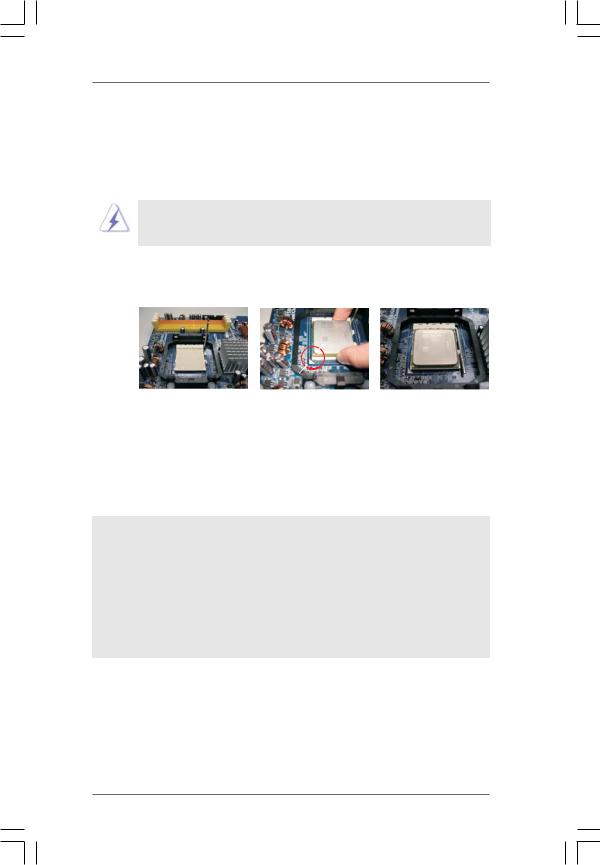
2.1CPU Installation
Step 1. Unlock the socket by lifting the lever up to a 90o angle.
Step 2. Position the CPU directly above the socket such that the CPU corner with the golden triangle matches the socket corner with a small triangle.
Step 3. Carefully insert the CPU into the socket until it fits in place.
The CPU fits only in one correct orientation. DO NOT force the CPU into the socket to avoid bending of the pins.
Step 4. When the CPU is in place, press it firmly on the socket while you push down the socket lever to secure the CPU. The lever clicks on the side tab to indicate that it is locked.
Lever 90° Up
|
CPU Golden Triangle |
|
|
Socket Corner Small Triangle |
|
STEP 1: |
STEP 2 / STEP 3: |
STEP 4: |
Lift Up The Socket Lever |
Match The CPU Golden Triangle |
Push Down And Lock |
|
To The Socket Corner Small |
The Socket Lever |
|
Triangle |
|
2.2 Installation of CPU Fan and Heatsink
After you install the CPU into this motherboard, it is necessary to install a larger heatsink and cooling fan to dissipate heat. You also need to spray thermal grease between the CPU and the heatsink to improve heat dissipation. Make sure that the CPU and the heatsink are securely fastened and in good contact with each other. Then connect the CPU fan to the CPU FAN connector (CPU_FAN1, see Page 10, No. 3). For proper installation, please kindly refer to the instruction manuals of the CPU fan and the heatsink.
13
2.3 Installation of Memory Modules (DIMM)
This motherboard provides four 240-pin DDRII (Double Data Rate II) DIMM slots, and supports Dual Channel Memory Technology. For dual channel configuration, you always need to install identical (the same brand, speed, size and chiptype) DDRII DIMM pair in the slots of the same color. In other words, you have to install identical DDRII DIMM pair in Dual Channel A (DDRII_1 and DDRII_2; Yellow slots; see p.10 No.6) or identical DDRII DIMM pair in Dual Channel B (DDRII_3 and DDRII_4; Orange slots; see p.10 No.7), so that Dual Channel Memory Technology can be activated. This motherboard also allows you to install four DDRII DIMMs for dual channel configuration, and please install identical DDRII DIMMs in all four slots. You may refer to the Dual Channel Memory Configuration Table below.
Dual Channel Memory Configurations
|
DDRII_1 |
DDRII_2 |
DDRII_3 |
DDRII_4 |
|
(Yellow Slot) |
(Yellow Slot) |
(Orange Slot) |
(Orange Slot) |
(1) |
Populated |
Populated |
- |
- |
(2) |
- |
- |
Populated |
Populated |
(3)* |
Populated |
Populated |
Populated |
Populated |
|
|
|
|
|
*For the configuration (3), please install identical DDRII DIMMs in all four slots.
1.If you want to install two memory modules, for optimal compatibility and reliability, it is recommended to install them in the slots of the same color. In other words, install them either in the set of yellow slots (DDRII_1 and DDRII_2), or in the set of orange slots (DDRII_3 and DDRII_4).
2.If only one memory module or three memory modules are installed in the DDRII DIMM slots on this motherboard, it is unable to activate the Dual Channel Memory Technology.
3.If a pair of memory modules is NOT installed in the same Dual Channel, for example, installing a pair of memory modules in DDRII_1 and DDRII_3, it is unable to activate the Dual Channel Memory Technology .
4.It is not allowed to install a DDR memory module into DDRII slot; otherwise, this motherboard and DIMM may be damaged.
14
Installing a DIMM
Please make sure to disconnect power supply before adding or removing DIMMs or the system components.
Step 1. Unlock a DIMM slot by pressing the retaining clips outward.
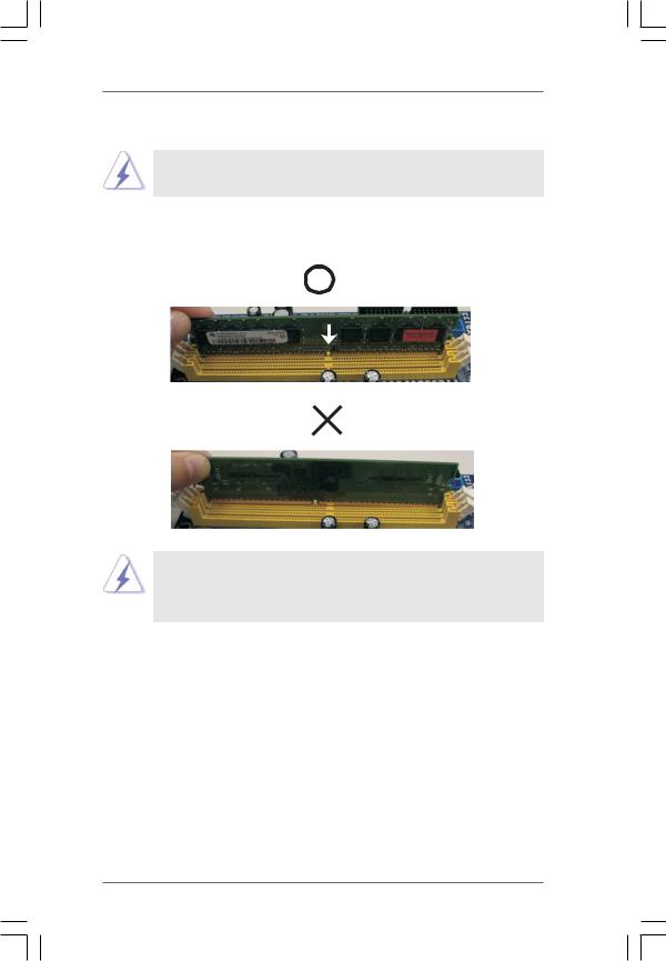
Step 2. Align a DIMM on the slot such that the notch on the DIMM matches the break on the slot.
 notch
notch  break
break
 notch
notch  break
break
The DIMM only fits in one correct orientation. It will cause permanent damage to the motherboard and the DIMM if you force the DIMM into the slot at incorrect orientation.
Step 3. Firmly insert the DIMM into the slot until the retaining clips at both ends fully snap back in place and the DIMM is properly seated.
15

2.4 Expansion Slots (PCI and PCI Express Slots)
There are 3 PCI slots and 3 PCI Express slots on this motherboard.
PCI Slots: PCI slots are used to install expansion cards that have the 32-bit PCI interface.
PCIE Slots: PCIE1 / PCIE3 (PCIE x1 slot) is used for PCI Express cards with x1 lane width cards, such as Gigabit LAN card, SATA2 card, etc. PCIE2 (PCIE x16 slot) is used for PCI Express cards with x16 lane width graphics cards.
Installing an expansion card
Step 1. Before installing the expansion card, please make sure that the power supply is switched off or the power cord is unplugged. Please read the documentation of the expansion card and make necessary hardware settings for the card before you start the installation.
Step 2. Remove the system unit cover (if your motherboard is already installed in a chassis).
Step 3. Remove the bracket facing the slot that you intend to use. Keep the screws for later use.
Step 4. Align the card connector with the slot and press firmly until the card is completely seated on the slot.
Step 5. Fasten the card to the chassis with screws. Step 6. Replace the system cover.
16
2.5 Jumpers Setup
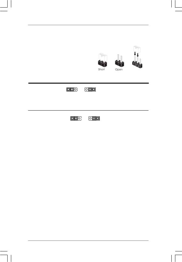
The illustration shows how jumpers are setup. When the jumper cap is placed on pins, the jumper is “Short”. If no jumper cap is placed on pins, the jumper is “Open”. The illustration shows a 3-pin jumper whose pin1 and
pin2 are “Short” when jumper cap is placed on these 2 pins.
Jumper |
|
Setting |
|
PS2_USB_PW1 |
1_2 |
2_3 |
Short pin2, pin3 to enable |
(see p.10, No. 1) |
+5V |
+5VSB |
+5VSB (standby) for PS/2 or |
|
USB wake up events. |
||
|
|
|
Note: To select +5VSB, it requires 2 Amp and higher standby current provided by power supply.
Clear CMOS Jumper |
1_2 |
2_3 |
(CLRCMOS1) |
|
|
(see p.10, No. 9) |
Default |
Clear CMOS |
Note: CLRCMOS1 allows you to clear the data in CMOS. The data in CMOS includes system setup information such as system password, date, time, and system setup parameters. To clear and reset the system parameters to default setup, please turn off the computer and unplug the power cord from the power supply. After waiting for 15 seconds, use a jumper cap to short pin2 and pin3 on CLRCMOS1 for 5 seconds. However, please do not clear the CMOS right after you update the BIOS. If you need to clear the CMOS when you just finish updating the BIOS, you must boot up the system first, and then shut it down before you do the clear-CMOS action.
17
 Loading...