

Page 1

RSGu3502
Residential Seamless Mobility Gateway
User Guide
Page 2

Copyright © 2007 RSGu3502 Residential Seamless Mobility Gateway by Motorola, Inc.
All rights reserved. No part of this publication may be reproduced in any f orm or by any means or used to make any derivative work (such as translation,
transformation or adaptation) without written permission from Motorola, Inc.
MOTOROLA and the Stylized M logo and SURFboard are registered in the US Patent and Trademark Office. Micr osoft Windows XP, and Windows 2000
are registered trademarks of Microsoft Corporation in the United States and/or other countries. Microsoft Windows screen shots are used by permission
of Microsoft Corporation. Wi-Fi is a registered trademark of the Wi-Fi Alliance, Inc. All other product or service names are the property of their
respective owners.
Motorola reserves the right to revise this publication and to make changes in content f r om time to time without obligation on the part of Motorola to provi de
notification of such revision or change. Motorola provides this guide without warranty of any kind, either implied or expressed, including, but not limited to,
the implied warranties of merchantability and fitness for a particul ar purpose. Motorola may make improvements or changes in the product(s) described in
this manual at any time.
Page 3

Table of Contents
Safety and Compliance Information ............................................................................... v
Important VoIP Telephone Service and 112 Information for Denmark ................................v
Internet Telephone Service and 999/112 in the United Kingdom .......................................vi
Internet Telephone Service and 911 in Canada.................................................................. vii
Internet Telephone Service and 911 in the United States................................................. viii
Important Safety Information..............................................................................................ix
FCC and IC Compliance Information............................................................................ xiii
FCC Interference Statement............................................................................................. xiii
FCC Radiation Exposure Statement ................................................................................. xiv
Industry Canada (IC) Statement........................................................................................xiv
IC Radiation Exposure Statement......................................................................................xv
Wireless LAN Information .................................................................................................xv
Restrictions on the Use of Wireless Devices ...................................................................xvi
International Declaration of Conformity ........................................................................... xvii
Overview ........................................................................................................................... 1
RSGu3502 Front Panel Overview ....................................................................................... 3
RSGu3502 Rear Panel Overview ........................................................................................ 5
Positioning Your RSGu3502 for Optimal Wireless Performance ........................................ 6
Anti-Fraud Protection Information.................................................................................. 7
If your device is stolen .......................................................................................................7
SIM Fraud Control...............................................................................................................7
Table of Contents i
Page 4

Table of Contents
Connecting Your RSGu3502.............................................................................................9
Troubleshooting RSGu3502 Connections .........................................................................10
Connecting Wirelessly to the RSGu3502 ..........................................................................12
RSGu3502 Setup — Basic Configurations ....................................................................13
Logging into the RSGu3502 ..............................................................................................14
Exporting the RSGu3502 Configuration ............................................................................14
Importing the Saved Configuration....................................................................................15
Restoring the Defaults for the RSGu3502.........................................................................15
WAN Configuration ...........................................................................................................16
WAN Setup for PPPoE (DSL) ............................................................................................17
WAN Setup for a Static IP Address (Cable Modem) .........................................................19
WAN Setup for DHCP (Cable Modem)..............................................................................20
Setup - LAN Configuration.................................................................................................21
RSGu3502 — Advanced Configuration .........................................................................25
Port Forwarding.................................................................................................................26
DMZ Settings ....................................................................................................................28
Custom Port Forwarding ...................................................................................................29
IP Filters ............................................................................................................................31
Custom IP Filters...............................................................................................................33
LAN Clients .......................................................................................................................35
Web Filters ........................................................................................................................36
Dynamic DNS Client..........................................................................................................37
ii Table of Contents
Page 5

Multicast ........................................................................................................................... 38
Static Routing ................................................................................................................... 39
Dynamic Routing .............................................................................................................. 40
Remote Web Access........................................................................................................ 42
Remote SSH Access ........................................................................................................ 43
Ethernet Switch................................................................................................................ 44
RSGu3502 — Tools......................................................................................................... 45
Restore Defaults............................................................................................................... 46
Import/Export Configuration ............................................................................................. 47
Remote Log — Router...................................................................................................... 48
Ping Test........................................................................................................................... 49
Restart .............................................................................................................................. 50
RSGu3502 — Status ....................................................................................................... 51
Network Statistics ............................................................................................................ 52
Connection Status ............................................................................................................ 53
DDNS Update Status........................................................................................................ 54
DHCP Clients ....................................................................................................................54
Product Information.......................................................................................................... 54
System Log – Router........................................................................................................ 54
RSGu3502 — Wireless Configuration ........................................................................... 55
Setting Up Your Wireless LAN (WLAN)............................................................................ 55
Establishing Security for Your Wireless LAN.................................................................... 57
Table of Content s
Table of Contents iii
Page 6

Table of Contents
Configuring WPA for Your Residential Gateway ...............................................................58
Configuring WEP on the Residential Gateway ..................................................................58
Creating an Access List for Your Wireless LAN ................................................................60
Configuring TCP/IP..........................................................................................................61
Configuring TCP/IP in Windows 2000 ...............................................................................61
Configuring TCP/IP in Windows XP...................................................................................66
Verifying the IP Address in Windows 2000 or Windows XP .............................................69
Frequently Asked Questions ..........................................................................................71
Troubleshooting Your RSGu3502 ..................................................................................73
Resetting All of Your Equipment .......................................................................................74
Glossary ...........................................................................................................................75
RSGu3502 — Software License .....................................................................................83
iv Table of Contents
Page 7

Safety and Compliance Information
Important VoIP Telephone Service and 112 Information for Denmark
Your VoIP Telephone Company provides customer with access to public emergency call services. When you
dial 112, your call is routed from their network to emergency operators who will handle your call. Contact
your provider for information about their VoIP 112 services.
IMPORTANT: When using this residential gateway, you CANNOT make any calls,
including an emergency call, and the emergency call operator WILL NOT be able to
locate where you are calling from, under the following circumstances:
!
When using this residential gateway, you may be able to make an emergency call to an operator, but it may
not be possible to locate where you are calling from, under the following circumstances:
• You have changed the physical address of your voice gateway, and you did not update or otherwise
advise your VoIP telephone service provider of this change.
• You are using a non-Danish telephone number.
• There are delays in making your location information available in or through the local automatic location
information database.
Note:
Your VoIP service provider, not Motorola, is responsible for the provisioning of telephone services through
this equipment. Motorola shall not be liable for, and expressly disclaims, any direct or indirect liabilities, damages, losses, claims, demands, actions, causes of action, risks or harms arising from or related to the services provided through this equipment.
• Your broadband Internet Service Provider (ISP) connection goes down, is lost, or
otherwise fails
• You lose electrical power
• Your broadband, ISP, or VoIP telephone service is suspended or terminated.
Safety and Compliance Information v
Page 8

Safety and Compliance Information
Internet Telephone Service and 999/112 in the United Kingdom
Your VoIP Telephone Company provides customer with access to public emergency call services. When you
dial 999/112, your call may be routed from your VoIP provider’s network to a national emergency operator
who will handle your call. Contact your provider for information about their VoIP 999/112 services.
IMPORTANT: When using this residential gateway, you CANNOT make any calls,
including an emergency call, and 999 location services WILL NOT be available, under the
following circumstances:
!
When using this residential gateway, you may be able to make an emergency call to an operator, but E999
location services may not be available, under the following circumstances:
• You have changed the physical address of your voice gateway, and you did not update or otherwise
advise your VoIP telephone provider of this change.
• You are using a non-U.K. telephone number.
• There are delays in making your location information available in or through the local automatic location
information database.
• Your broadband Internet Service Provider (ISP) connection goes down, is lost, or
otherwise fails
• You lose electrical power
• Your broadband, ISP, or VoIP service is suspended or terminated
Note:
Your VoIP service provider, not Motorola, is responsible for the provision of VoIP telephone services through
this equipment. Motorola shall not be liable for, and expressly disclaims, any direct or indirect liabilities, damages, losses, claims, demands, actions, causes of action, risks or harms arising from or related to the services provided through this equipment.
vi Safety and Compliance Information
Page 9

Safety and Compliance Information
Internet Telephone Service and 911 in Canada
Your VoIP telephone company provides customer with access to public emergency call services. VoIP
telephone companies may offer a form of 9-1-1 service (9-1-1 Dialing) that is similar to traditional 9-1-1 (911)
service but could have some important differences and limitations when compared with enhanced 9-1-1
service (E911) available in most locations in conjunction with traditional telephone service. Contact your
provider for information about their VoIP 911 services.
IMPORTANT: When using this residential gateway, you CANNOT make any calls,
including an emergency call, and E911 location services WILL NOT be available, under
the following circumstances:
!
You should inform any household residents, guests and other persons who may be present at the physical
location where you utilize VoIP telephone service, of the important differences in and possible limitations of
VoIP 9-1-1 Dialing services.
Note:
Your VoIP service provider, not Motorola, is responsible for the provisioning of telephone services through
this equipment. Motorola shall not be liable for, and expressly disclaims, any direct or indirect liabilities,
damages, losses, claims, demands, actions, causes of action, risks or harms arising from or related to the
services provided through this equipment.
• Your broadband Internet Service Provider (ISP) connection goes down, is lost, or
otherwise fails
• You lose electrical power
• Your broadband, ISP, or VoIP service is suspended or terminated
Safety and Compliance Information vii
Page 10

Safety and Compliance Information
Internet Telephone Service and 911 in the United States
IMPORTANT: When using this residential gateway, you CANNOT make any calls,
including an
the following circumstances:
!
When using this residential gateway, you may be able to make an emergency call to an operator, but E911 location
services may not be available, under the following circumstances:
• You have changed the physical address of your residential gateway, and you did not update or otherwise
advise your service provider of this change.
• You are using a non-U.S. telephone number.
• There are delays in making your location information available in or through the local automatic location
information database.
Contact your VoIP Service Provider for additional information on their 911 protocols.
• Your broadband Internet Service Provider (ISP) connection goes down, is lost, or
otherwise fails
• You lose electrical power
• Your broadband, ISP, or VoIP service is suspended or terminated
emergency call, and E911 location services WILL NOT be available, under
Note:
Your VoIP Service Provider, not Motorola, is responsible for the provision of telephone services through this
equipment. Motorola shall not be liable for, and expressly disclaims, any direct or indirect liabilities, damages, losses, claims, demands, actions, causes of action, risks or harms arising from or related to the services provided through this equipment.
viii Safety and Compliance Information
Page 11

Safety and Compliance Information
Important Safety Information
When using your telephone equipment, basic safety precautions should always be followed to reduce the
risk of fire, electric shock, and injury to persons, including the following:
• Read all of the instructions listed here and/or in the user manual before you operate this device. Give
particular attention to all safety precautions. Retain the instructions for future reference.
• This device must be installed and used in strict accordance with manufacturer's instructions as
described in the user documentation that is included with the device.
• Comply with all warning and caution statements in the instructions. Observe all warning and caution
symbols that are affixed to this device.
• To prevent fire or shock hazard, do not expose this device to rain or moisture. The device must not be
exposed to dripping or splashing. Do not place objects filled with liquids, such as vases, on the device.
• To prevent electric shock, this device may require a grounding conductor in the line cord. Connect the
device to a grounding type AC wall outlet using the power cord supplied with the device.
• This device was qualified under test conditions that included the use of the supplied cables between
systems components. To ensure regulatory and safety compliance, use only the provided power and
interface cables and install them properly.
Safety and Compliance Information ix
Page 12

Safety and Compliance Information
• Different types of cord sets may be used for connections to the main supply circuit. Use only a main line
cord that complies with all applicable device safety requirements of the country of use.
• Installation of this device must be in accordance with national wiring codes and conform to local
regulations.
• Operate this device only from the type of power source indicated on the device's marking label. If you
are not sure of the type of power supplied to your home, consult your dealer or local power company.
• Do not overload outlets or extension cords, as this can result in a risk of fire or electric shock.
Overloaded AC outlets, extension cords, frayed power cords, damaged or cracked wire insulation, and
broken plugs are dangerous. They may result in a shock or fire hazard.
• Route power supply cords so that they are not likely to be walked on or pinched by items placed upon or
against them. Pay particular attention to cords where they are attached to plugs and convenience
receptacles, and examine the point where they exit from the device.
• Place this device in a location that is close enough to an electrical outlet to accommodate the length of
the power cord.
• Place device to allow for easy access when disconnecting the power cord of the device from the AC
wall outlet.
x Safety and Compliance Information
Page 13

Safety and Compliance Information
• Do not connect the plug into an extension cord, receptacle, or other outlet unless the plug can be fully
inserted with no part of the blades exposed.
• Place this device on a stable surface.
• It is recommended that the customer install an AC surge protector in the AC outlet to which this device
is connected. This is to avoid damaging the device by local lightning strikes and other electrical surges.
• Postpone installation until there is no risk of thunderstorm or lightning activity in the area.
• Avoid using a telephone (other than a cordless type) during an electrical storm. There may be a remote
risk of electric shock from lightning. For added protection, unplug the device from the wall outlet and
disconnect the cables to avoid damage to this device due to lightning and power surges.
• Do not cover the device or block the airflow to the device with any other objects. Keep the device away
from excessive heat and humidity and keep the device free from vibration and dust.
• Wipe the device with a clean, dry cloth. Never use cleaning fluid or similar chemicals. Do not spray
cleaners directly on the device or use forced air to remove dust.
• CAUTION: To reduce the risk of fire, use only No. 26 AWG or larger (e.g., 24 AWG) UL Listed or CSA
Certified Telecommunication Line Cord, or national equivalent.
• Disconnect TNV circuit connector(s) before disconnecting power.
Safety and Compliance Information xi
Page 14

Safety and Compliance Information
• Disconnect TNV circuit connector before removing cover.
• Do not use this product near water; for example, near a bathtub, washbowl, kitchen sink or laundry tub,
in a wet basement, or near a swimming pool.
• Do not use the telephone to report a gas leak in the vicinity of the leak.
• Use only the power cord and batteries indicated in this manual. Do not dispose of batteries in a fire. They
may explode. Check with local codes for possible disposal instructions.
• Upon completion of any service or repairs to this device, ask the service technician to perform safety
checks to determine that the device is in safe operating condition.
• Do not open the device. Do not perform any servicing other than that contained in the installation and
troubleshooting instructions. Refer all servicing to qualified service personnel.
• SAVE THESE INSTRUCTIONS
xii Safety and Compliance Information
Page 15

FCC and IC Compliance Information
FCC and IC Compliance Information
FCC Interference Statement
This equipment has been tested and found to comply with the limits for a Class B digital device, pursuant to
part 15 of the FCC Rules. These limits are designed to provide reasonable protection against harmful interference in a residential environment. This equipment generates, uses, and can radiate radio frequency
energy and, if not installed and used in accordance with the instructions, may cause harmful interference to
radio communications. However, there is no guarantee that interference will not occur in a particular installation. If this equipment does cause harmful interference to radio or television reception, which can be determined by turning the device off and on, the user is encouraged to try to correct the interference by one or
more of the following measures:
• Reorient or relocate the receiving antenna.
• Increase the separation between the device and receiver.
• Connect the equipment into an outlet on a circuit different from that to which the receiver is connected.
• Consult the dealer or an experienced radio/TV technician for help.
This device complies with part 15 of the FCC Rules. Operation is subject to the following two conditions: (1)
This device may not cause harmful interference, and (2) This device must accept any interference received,
including interference that may cause undesired operation.
FCC CAUTION: Any changes or modifications not expressly approved by Motorola for compliance could void
the user's authority to operate the equipment.
FCC and IC Compliance Information xiii
Page 16

FCC and IC Compliance Information
FCC Radiation Exposure Statement
IMPORTANT NOTE:
This equipment complies with FCC radiation exposure limits set forth for an uncontrolled environment. To
comply with the FCC RF exposure compliance requirements, the separation distance between the antenna
and any person's body (including hands, wrists, feet and ankles) must be at least 20 cm (8 inches).
This transmitter must not be co-located or operated in conjunction with any other antenna or transmitter.
The availability of some specific channels and/or operational frequency bands are country dependent and are
firmware programmed at the factory to match the intended destinations. The firmware setting is not accessible by the end user.
Industry Canada (IC) Statement
This device complies with RSS-210 of the Industry Canada Rules. Operation is subject to the following two
conditions:
1 This device may not cause interference, and
2 This device must accept any interference, including interference that may cause undesired operation of
the device.
This device has been designed to operate with an antenna having a maximum gain of
having a higher gain is strictly prohibited per regulations of Industry Canada. The required antenna impedance is 50 ohms.
To reduce potential radio interference to other users, the antenna type and its gain should be so
chosen that the equivalent isotropically radiated power (e.i.r.p) is not more than that permitted for successful
communications.
xiv FCC and IC Compliance Information
2dBi. An antenna
Page 17

FCC and IC Compliance Information
IC Radiation Exposure Statement
MPORTANT NOTE:
This equipment complies with IC radiation exposure limits set forth for an uncontrolled environment. This
equipment should be installed and operated with a minimum distance of 20 cm (approximately 8 inches)
between the radiator and your body.
This Class B digital apparatus complies with Canadian ICES-003.Cet appareil numérique de la classe B est
conforme à la norme NMB-003 du Canada.
Wireless LAN Information
This device is a wireless network product that uses Direct Sequence Spread Spectrum (DSSS) radio technology. The device is designed to be inter-operable with any other wireless DSSS product that complies with:
• The IEEE 802.11 Standard on Wireless LANs (Revision B and Revision G), as defined and approved by
the Institute of Electrical Electronics Engineers
FCC and IC Compliance Information xv
Page 18

FCC and IC Compliance Information
Restrictions on the Use of Wireless Devices
In some situations or environments, the use of wireless devices may be restricted by the proprietor of the
building or responsible representatives of the organization: for example, using wireless equipment in any
environment where the risk of interference to other devices or services is perceived or identified as harmful.
If you are uncertain of the applicable policy for the use of wireless equipment in a specific organization
or environment, you are encouraged to ask for authorization to use the device prior to turning on
the equipment.
The manufacturer is not responsible for any radio or television interference caused by unauthorized modification of the devices included with this product, or the substitution or attachment of connecting cables and
equipment other than specified by the manufacturer. Correction of the interference caused by such unauthorized modification, substitution, or attachment is the responsibility of the user.
The manufacturer and its authorized re-sellers or distributors are not liable for any damage or violation of
government regulations that may arise from failing to comply with these guidelines.
xvi FCC and IC Compliance Information
Page 19

FCC and IC Compliance Information
International Declaration of Conformity
We,
Motorola, Inc.
Connected Home Solutions
101 Tournament Drive
Horsham, PA 19044, USA
1-215-323-1000
declare under our sole responsibility that the
RSGu3502 Residential Seamless Mobility Gateway
To which the declaration relates is in conformity with the following standards:
EN 60950-1
EN 300 328
EN 301 489-1/-17
EN 61000-3-2
EN 61000-3-3
The following provisions of the Directive(s) of the Council of the European Union:
EMC Directive 89/336/EEC
Low Voltage Directive 73/23/EEC
R&TTE Directive 1999/5/EC
Waste Electrical and Electronic Equipment (WEEE) Directive 2002/96/EC
Restriction of the Use of Certain Hazardous Substances in Electrical Equipment (RoHS)
Directive 2002/95/EC
FCC and IC Compliance Information xvii
Page 20

FCC and IC Compliance Information
Caring for the Environment by Recycling
When you see this symbol on a Motorola product, do not dispose of the product with
residential or commercial waste.
Recycling your Motorola Equipment
Please do not dispose of this product with your residential or commercial waste. Some countries or regions, such as the European Union, have set up systems to collect and recycle
electrical and electronic waste items. Contact your local authorities for information about
practices established for your region. If collection systems are not available, call Motorola
Customer Service for assistance.
xviii FCC and IC Compliance Information
Page 21
Overview
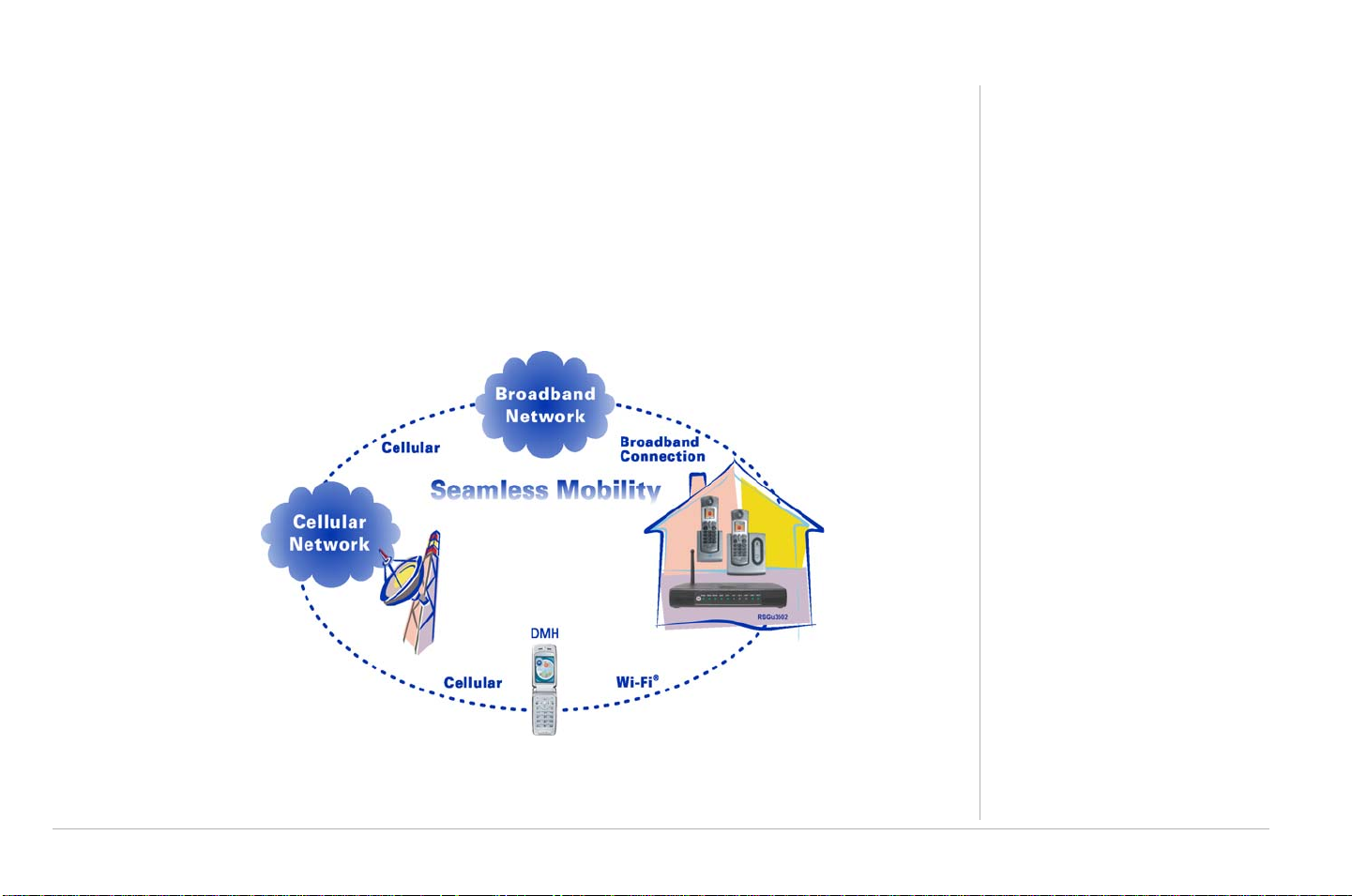
Congratulations on your purchase of a Motorola RSGu3502 Residential Seamless Mobility Gateway. A key
feature of the RSGu3502 is the ability to seamlessly transfer calls between Broadband and
Cellular Networks.
Construction materials and other objects, such as appliances and televisions, often interfere with mobile
service indoors. Use the RSGu3502 with a dual mode mobile handset (DHM) and you can use your home’s
WiFi™ network to stay connected. Voice traffic is prioritized over Internet traffic, giving you high-quality
voice calls even while surfing the Web.
You will need:
• A computer with Internet
browsing capability
• An established DSL or cable
Internet connection
• Windows
Additional Needs
®
2000, Windows XP
™
• For a DSL connection only, your
user name and password
• For a cable modem connection
using static IP addresses only,
your IPaddress, subnet mask,
default gateway, and DNS and
server IP address or addresses
Overview 1
Page 22

Overview
In the box with your RSGu3502:
RSGu3502 Features
Your new residential gateway is designed to:
• Support up to two telephone lines with full-featured service (Voice mail, caller ID, call waiting, three-way
calling, and other CLASS services)
• Provide seamless mobile and landline voice and data communication
AC Adapter
CD ROM w/ User Guide
Ethernet Cables
RSGu3502
Quick Start
Guide
CD ROM
Vertical Mounting Stand
(not pictured)
• Optimize dual-mode handset battery performance
• Plug and play—plugs into any broadband connection (cable or DSL)
• Give voice-over-data prioritization (talk on the phone while using the Internet, without a noticeable
reduction in voice quality)
• Eliminate the need for stand-alone routers, hubs, and access points—the RSGu3502 has a built-in router
and firewall with 802.11b/g wireless access point
• Allow VPN pass-through for remote access via IPSEC/PPTP/L2TP NAT tunneling
2Overview
Page 23
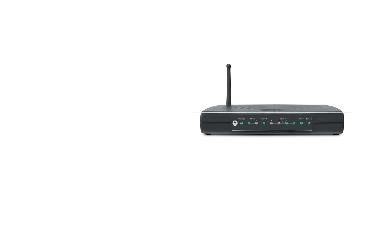
RSGu3502 Front Panel Overview
Light Description
Wireless Indicates the status of the wireless network:
• Solid green, the wireless network is available.
• Green and flashing, there is wireless network activity.
• Off, the wireless network is not engaged.
Phone 1, 2 • Solid green, registration is complete, the phone for that line is on hook and
ready for use. No voice mail present.
• Green and flashing, registration is complete, the phone is ringing,
and/or voice mail is present.
• Orange and flashing, indicates that the phone is off hook and no SIM
card is present.
• Flashing in unison with the other LED lights, the residential gateway
is downloading a firmware upgrade. Please do not unplug or
disconnect your residential gateway while it is downloading
firmware.
• Red blinking, phone off hook and registration error.
• LED off, registration error, the phone is on hook, and/or no SIM card
is present. You cannot use it for phone calls.
Overview
Internet Indicates the Internet connection speed:
• Solid green, your connection speed is 100Base-T
• Solid yellow, your connection speed is 10Base-T
The LED flashes when there is activity on the Internet connection.
Overview 3
Page 24

Overview
Light Description
Ethernet
1, 2, 3, and 4
Power If the Power LED is red or orange — flashing or solid — restart the residential gateway.
Pairing This is a future feature. It will be enabled in a future update.
Indicates that a device is connected to the port and the speed of the Ethernet connection:
• Off, no device is connected to the port
• Solid green, a device is connected to the port (100Base-T)
• Solid yellow, a device is connected to the port (10Base-T)
A flashing yellow or green LED indicates that there is activity on the Ethernet connection.
During the power up, the residential gateway flashes several times while connecting, retrieving the IP
address, and downloading configuration information.
• Solid green, configuration download complete.
• During firmware downloads (optional), the Phone and Power LEDs flash rapidly. Please do not unplug
or disconnect your residential gateway while it is downloading firmware.
4Overview
Page 25
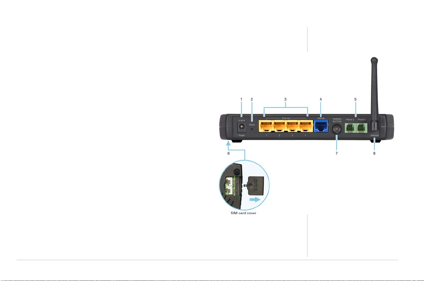
RSGu3502 Rear Panel Overview
Key Item Description
1Power Connector for the AC power adapter.
2 Reset One quick press will restart the unit.
Hold the button for 10 seconds to reset the unit.
Overview
3 Ethernet 1, 2,
3, 4
4 Internet Connect your cable or DSL modem to the RSGu3502.
5 Phone
1and2
6SIM Card
Compartment
7Pairing Future feature
8Antenna Rotatable antenna used for wireless connections.
Use the yellow Ethernet ports to connect up to four devices
(computers, gaming machines, printers, etc.)
Connect one or two phones to one and two (optional).
Holds the SIM Card(s) used to make and receive calls on the
landline phone connected to the residential gateway.
A valid and active SIM card must be connected to the
corresponding telephone port (e.g., If your phone is
connected to port one insert your SIM card in slot one).
Overview 5
Page 26

Overview
Positioning Your RSGu3502 for Optimal Wireless Performance
Review the guidelines below before deciding where to place your RSGu3502 in order to achieve the best
wireless performance:
• Connect at least one computer through a wired Ethernet connection.
• Placing your RSGu3502 in the physical center of your network is best, because its antenna sends out signals in all
directions.
• Placing the RSGu3502 in a higher location, such as on top of a cabinet, helps disperse the signal cleanly , especially
to upper floors.
• If possible, position your RSGu3502 in direct line of sight with other home network devices using
a wireless connection.
• Avoid placing the RSGu3502 next to large, solid objects like computer cases, monitors, walls, fireplaces, etc. This
helps the signal penetrate more cleanly.
• Other wireless devices, such as televisions, radios, microwaves, or 2.4 GHz cordless telephones, can interfere with
the signal. Keep these devices away from the RSGu3502.
• Mirrors, especially those that are silver-coated, can reduce transmission performance.
6Overview
Page 27

Anti-Fraud Protection Information
Anti-Fraud Protection Information
To prevent the RSGu3502 Residential Gateway and/or your Subscriber Identity Module (SIM) Card from
being stolen and reused, please incorporate the security options listed below:
If your device is stolen
Immediately notify your service provider if the RSGu3502 is stolen.
SIM Fraud Control
Your service provider will give you a PIN that you are prompted to enter at every power-up. The SIM PIN is
enabled when you purchase your RSGu3502.
To enter you SIM PIN, first make sure your telephone is connected:
1 Power up your residential gateway.
2 Wait for your handset to ring.
3 Pick up the telephone handset. You will hear a stutter tone.
4 Enter you SIM PIN. If you enter the incorrect PIN you will hear the stutter tone again.
5 Listen for a dial tone. When you hear the dial tone, you have completed the validation process.
!
CAUTION:
After two incorrect PIN entries, the system hangs up and blocks the SIM PIN. Contact
your service provider for additional assistance.
Anti-Fraud Protection Information 7
Page 28

Anti-Fraud Protection Information
Use this space to keep your PIN information
8 Anti-Fraud Protection Information
Page 29
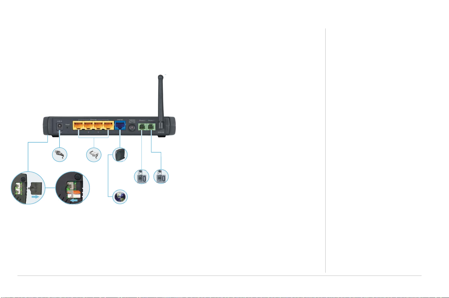
Connecting Your RSGu3502
NOTES: At least one computer on your network must be connected to the RSGu3502 using an Ethernet cable. Also, to prevent damage, only insert your SIM card with the power off.
1 Shut down your computer and unplug your
cable or DSL modem power cord.
2 Disconnect your computer from the modem.
Do not disconnect your modem from the cable
or phone line that provides your Internet
RSGu3502
connection.
3 Connect one end of the blue Ethernet cable to
the Ethernet port on your modem. Plug the
other end to the blue Ethernet port on the rear
panel of your residential gateway.
Power
Four-Port
Ethernet Router
Cable or
DSL Modem
4 Connect one end of the yellow Ethernet cable
to the yellow Ethernet port on your residential
gateway, and the other end of the cable to the
Phone
Phone
port on your computer.
5 Open the SIM slot and insert your card. (Note:
Remove SIM card cover Insert SIM card
Internet
Place your SIM card and telephone in the
corresponding ports (SIM Port 1:Phone1/SIM
Port2:Phone2). Replace the door.
6 Connect a landline telephone.
7 Plug your cable or DSL modem back into an electrical outlet.
8 Connect the power adapter to the Power port on the rear panel of the RSG, and plug the other end into
an electrical outlet.
Connecting Your RSGu3502 9
Page 30

Connecting Your RSGu3502
9 Turn on your computer. The Ethernet light on the RSGu3502 front panel should light.
10 Test your connection. Open a web browser and enter any website address (you can try
www.motorola.com). If you have DSL, you will need to enter your Username and Password (“WAN
Setup for PPPoE (DSL)” on page 17). If you can access the site, you have successfully installed your
residential gateway.
11 Repeat step four to connect additional devices using Ethernet cables.
Troubleshooting RSGu3502 Connections
If your test (STEP 10) is not successful, and you connect to the Internet using a:
Cable Modem — Turn your cable modem off again for at least 10 minutes. If this does not correct your prob-
lem, you may need to register your RSGu3502 with your cable provider. Please contact them to update your
information. Be sure to have the WAN MAC ID (located on the bottom of the RSGu3502) available.
DSL Modem — You may need to set the PPPoE configurations.
1 Open a web browser from a computer connected to one of the RSGu3502 Ethernet ports.
2 Ty p e http://192.168.15.1 in the address field and press ENTER to access the sign in window.
3 Ty p e router in the Username and Password fields (the default is router for both fields).
4 Click SETUP (located on the top menu bar), and then click on WAN Configuration (located on menu bar
at the left side of the page).
10 Connecting Your RSGu3502
Page 31

Connecting Your RSGu3502
5 Select PPPoE from the Type drop down menu. Note: It is recommended that the NAT and Firewall
options remain checked.
6 Type the Username and Password you normally use to log into your DSL service.
7 Ty p e 0 i n th e Keep Alive field to ensure that your DSL link is always active.
8 Click Connect to start your Internet connection and then Click Save.
9 Open a web browser and enter a web address (try www.motorola.com). If you can access the site, you
have successfully completed the installation process.
Connecting Your RSGu3502 11
Page 32

Connecting Your RSGu3502
Connecting Wirelessly to the RSGu3502
To connect to your RSGu3502 wirelessly, your computer must have a 802.11b or 802.11g wireless adapter
installed. If all wireless security and encryption are disabled on the adapter and the RSGu3502, the computer will automatically connect to the residential gateway.
Note: Motorola ships the RSGu3502 with all wireless security functions disabled.
Remember, at least one computer must be connected to the RSGu3502 using a wired connection in order
to perform the configuration. Do not attempt to configure the RSGu3502 over a wireless connection. After
your wireless LAN is operational, enable security.
RSGu3502
Wi-Fi
Wireless Access Point
12 Connecting Your RSGu3502
Power
Remove SIM card cover Insert SIM card
Four-Port
Ethernet Router
Cable or
DSL Modem
Internet
Phone
Phone
Page 33

RSGu3502 Setup — Basic Configurations
In most cases, you can start using your RSGu3502 with no modifications to the default settings. When you
need to or wish to modify the settings, the residential gateway has an easy to use GUI interface. Each section is defined on the HOME page.
RSGu3502 Setup — Basic Configurations 13
Page 34

RSGu3502 Setup — Basic Configurations
Logging into the RSGu3502
1 Open a Web browser on a computer connected to the RSGu3502.
2 Ty p e http://192.168.15.1 in the address field, and press enter.
3 Ty p e router in both the Username and Password fields (the default for both fields is “router”).
4 Click Log In to display the HOME page.
TIP:
*
Exporting the RSGu3502 Configuration
If you decide to modify the current RSGu3502 configuration, it is recommend that you create a backup. Follow the steps below to export the current configuration.
1 Click TOOLS from the top menu.
2 Click Import/Export Configuration on the side menu.
3 Click Export. The residential gateway configuration is saved to a file named config.bin on your
computer’s hard drive.
If DHCP is enabled on each computer connected to your network (LAN), there is no need to
change the default LAN settings. It is recommended that you do not change the LAN settings
unless you have sufficient networking knowledge.
14 RSGu3502 Setup — Basic Configurations
CD ROM
Page 35

RSGu3502 Setup — Basic Configurations
Importing the Saved Configuration
To return to the previous configuration, import the saved configuration.
1 Click TOOLS.
2 Click Import/Export Configuration.
3 Click Import. A new import window opens.
4 Click Browse or type the path and filename of the item you wish to import.
5 Click Import. The update status appears at the bottom of the window. When the update is
complete, the residential gateway restarts automatically. You will need to log in again.
Restoring the Defaults for the RSGu3502
1 Click TOOLS.
2 Click Restore Defaults on the side menu.
3 Click the Restore Defaults button.
RSGu3502 Setup — Basic Configurations 15
Page 36

RSGu3502 Setup — Basic Configurations
WAN Configuration
After logging into the residential gateway:
1 Click SETUP.
2 Click WAN Configuration.
3 Select PPPoE, Static, or DHCP fr om the pull dow n menu .
PPPoE
Used with all DSL modems. See WAN Setup for PPPoE (DSL).
Static
For some cable modems, the cable company assigns the cable modem a static (unchanging) IP address. You
must provide the IP address, subnet mask, default gateway, and one to three domain name server (DNS)
addresses. See WAN Setup for a Static IP Address (Cable Modem).
DHCP
Most cable modems have a dynamic IP address assigned by the cable company DHCP server. Typically, no
additional configuration is needed for the residential gateway. See DCHCP Settings.
16 RSGu3502 Setup — Basic Configurations
Page 37

WAN Setup for PPPoE (DSL)
Field or Button Description
RSGu3502 Setup — Basic Configurations
Options
User name
Password
Keep Alive
• NAT — Enables Network Address Translation (It is recommended that this item
remain selected)
• Firewall — Enables the residential gateway firewall (It is recommended that this item
remain selected)
Your PPPoE user name provided by your DSL provider.
Your PPPoE password provided by your DSL provider.
Enables persistent connection to the internet.
RSGu3502 Setup — Basic Configurations 17
Page 38

RSGu3502 Setup — Basic Configurations
Field or Button Description
Authentication Sets the authentication:
• Auto — Automatic
• CHAP — Challenge Handshake Authentication Protocol
• PAP — Password Authentication Protocol
Microsoft CHAP v2 is supported in the Auto and CHAP options. MS CHAP v1 is not
supported.
MTU The maximum transmission unit for the DSL connection. It is a negotiated value that
represents the maximum size in bytes of the packets sent over the connection. The default
is 1492. The maximum is 1500. The minimum is 64.
Override MAC If your cable or DSL provider associates a particular service to a specific device, such as
your computer, select this field and type that MAC address in the MAC field to use as a
“virtual” WAN MAC address instead of the residential gateway MAC address. By default,
the MAC address printed on the residential gateway is displayed in this field.
Restore Restores the actual residential gateway MAC address.
Enforce MTU If enabled (the default), all TCP segments must have a size within the PPPoE MTU. If you
disable this, you may have problems accessing some Internet sites.
Debug Enables PPPoE debugging for use by technical support personnel only.
Connect Establishes the DSL connection.
Disconnect Ends the DSL connection. If you disconnect your DSL connection, your VoIP service cannot
18 RSGu3502 Setup — Basic Configurations
work.
Page 39

WAN Setup for a Static IP Address (Cable Modem)
RSGu3502 Setup — Basic Configurations
Options
• NAT — EnablesNetwork Address Translation (It is recommended that this item remain selected)
• Firewall — Enables the residential gateway firewall (It is recommended that this item remain
selected)
Type the following in dotted-decimal format as assigned by your cable provider.
IP Address
Mask
Gateway
Override MAC
Default Gateway
DNS 1, 2, and 3
The static IP address
The subnet mask
The gateway IP address
If your cable or DSL provider associates a particular service to a specific device, such as your
computer, select this field and type that MAC address in the MAC field to use as a “virtual”
WAN MAC address instead of the residential gateway MAC address. By default, the MAC
address printed on the residential gateway is displayed in this field.
The default gateway IP address
One to three domain name server IP addresses
RSGu3502 Setup — Basic Configurations 19
Page 40

RSGu3502 Setup — Basic Configurations
WAN Setup for DHCP (Cable Modem)
Options
Optional fields and buttons are:
Override MAC
Restore
Renew
Release
20 RSGu3502 Setup — Basic Configurations
• NAT — Enables Network Address Translation (It is recommend that this item remain selected)
• Firewall — Enables the residential gateway firewall (It is recommend that this item remain
selected)
If your cable or DSL provider associates a particular service to a specific device, such as
your computer, select this field and type that MAC address in the MAC field to use as a
“virtual” WAN MAC address instead of the residential gateway MAC address. By default,
the MAC address printed on the residential gateway is displayed in this field.
Restores the actual residential gateway MAC address.
Requests a new WAN IP address for your residential gateway from the DHCP server.
Releases the residential gateway WAN IP address.
Page 41

RSGu3502 Setup — Basic Configurations
Setup - LAN Configuration
If DHCP is enabled on all of the computers on your home network (LAN), you should not need to change any
of the default LAN settings. For information about enabling DHCP, see “Configuring TCP/IP” on page 61.
Unless you have sufficient networking knowledge, we recommend not changing any LAN settings.
RSGu3502 Setup — Basic Configurations 21
Page 42

RSGu3502 Setup — Basic Configurations
Field or Button Description
Subnet IP Address
Netmask
Host Name
Domain
Enable DHCP Server
Assign ISP DNS,
SNTP
Sets your LAN subnetwork IP address in dotted-decimal format. We recommend not
changing the default 192.168.15 .1.
Sets the residential gateway subnet mask, in dotted-decimal format. The default is
255.255.255.0, which enables the residential gateway router to support up 253 users
connected through multiple hubs, switches, routers, or wireless access points.
Sets the residential gateway host name. It can contain any alphanumeric characters,
except spaces.
Sets the domain name. It is used in conjunction with the host name to uniquely identify
the residential gateway. To access the web pages of the residential gateway, you can
type 192.168.15.1 (the IP address) or mygateway1.Motorola_VT (hostmame.domain).
If selected, the DHCP server on the residential gateway assigns IP addresses to the
computers and other hosts on your network, if they have DHCP enabled (see
“Configuring TCP/IP” on page 61). By default, the residential gateway DHCP server is
enabled.
If there is another DHCP server running on your network (on another router), you must
disable one of the DHCP servers.
The residential gateway will use the DNS servers and time server (SNTP) provided
by your ISP.
22 RSGu3502 Setup — Basic Configurations
Page 43

Field or Button Description
RSGu3502 Setup — Basic Configurations
Start IP
End IP
Sets the first IP address assigned by the DHCP server, in dotted-decimal format. It must
be greater than the IP address value of the residential gateway. For example, if the IP
address of the residential gateway is 192.168.15.1 (default), the starting IP address
must be 192 .16 8.15.2 (or higher).
Sets the final IP address assigned by the DHCP server, in dotted-decimal format. It
cannot exceed the subnet limit of 254. For example, the default is 192.168.15.254. If the
DHCP server runs out of DHCP addresses, users cannot access network resources. If
this happens, increase the End IP (to the limit of 254) or reduce the Lease Time.
If you change Start IP or End IP, be sure they are in the range specified by the Subnet IP
Address and Netmask. For example, if the residential gateway IP address is
192.168.15.1 (the default) and you set Start IP and End IP to 192.168.0.2 and
192.168.0.100 respectively, computers with DHCP enabled cannot communicate with
the residential gateway.
RSGu3502 Setup — Basic Configurations 23
Page 44

RSGu3502 Setup — Basic Configurations
Field or Button Description
Lease Time
Enable DHCP Relay
Relay IP
Server and Relay Off
Sets the time, in seconds, that a network computer remains connected to the
residential gateway using its current assigned IP address. At the end of this time, the
DHCP server renews the lease or assigns the computer a new IP address. The default
is 3600 seconds (1 hour). The maximum is 999999 seconds (about 278 hours).
If selected, the residential gateway forwards requests and responses between the
computers on your network (the DHCP clients) and the DHCP server you chose to use
for your network.
If you select Enable DHCP Relay, type the IP address of the DHCP server in
dotted-decimal format.
If selected, you must carefully configure the IP address, Subnet Mask, and DNS
settings of every host on your network. Do not assign the same IP address to more
than one host. Your residential gateway must be on the same subnet as the
other hosts.
24 RSGu3502 Setup — Basic Configurations
Page 45

RSGu3502 — Advanced Configuration
See the main Advanced page for quick descriptions of each feature.
*
TIP: A red bullet point indicates that the feature is not enabled; a green bullet point indicates that
the feature is enabled. Universal Plug and Play (UPnP) requires one active WAN connection and
the host should support this feature.
RSGu3502 — Advanced Configuration 25
Page 46

RSGu3502 — Advanced Configuration
Port Forwarding
Port forwarding enables you to direct incoming traffic to specific LAN hosts (computers on your network)
based on the protocol and port number. It is used to play Internet games or provide local services (such as
web hosting) for a LAN group.
Port forwarding is also referred to as “virtual servers.” Use Port Forwarding to apply predefined rules, and, if
you have the necessary networking knowledge, create, edit, or delete your own port forwarding rules. You
can also add a computer to the DMZ.
26 RSGu3502 — Advanced Configuration
Page 47

RSGu3502 — Advanced Configuration
Field or Button Description
Allow Incoming Ping Enables the residential gateway to respond to a ping from the Internet.
LAN IP Selects the IP address to host the service.
New IP Displays the LAN Clients window to reserve an IP address.
DMZ Displays the IP Filters page.
Custom Port
Forwarding
Available Rules Lists the available rules in the selected Category.
View Displays the protocols and port ranges for the selected Available Rule. For example,
Add Adds the selected Available Rule to the Applied Rules list.
Remove Deletes the selected rule from the Applied Rules list.
Applied Rules Lists the IP filtering rules you selected to apply for each given category.
Displays the DMZ Settings page.
if you select Alien vs. Predator and click View, the following is displayed:
Click Cancel to return to the Port Forwarding page.
RSGu3502 — Advanced Configuration 27
Page 48

RSGu3502 — Advanced Configuration
DMZ Settings
Configuring a computer as a demilitarized zone (DMZ) forwards any network traffic that is not redirected to
another computer through port forwarding to the IP address of the computer. This allows access to the DMZ
host from the Internet.
Field Description
Enable DMZ Enables or disables the DMZ feature. It is disabled by default.
Select a LAN IP Address Selects the LAN IP address of the DMZ computer to expose to the Internet with no
protection from the RSGu3502 firewall. This may expose your network to security
risks.
LAN Clients Displays the LAN Clients page to configure the DMZ computer.
28 RSGu3502 — Advanced Configuration
Page 49

RSGu3502 — Advanced Configuration
Custom Port Forwarding
You can create up to 20 custom port forwarding entries to support specific services or applications, such as
concurrent NAT/NAPT operation.
Field Description
Enable It is selected by default and automatically applies when you click Save.
Application The name of the application for which ports are opened.
Protocol Can be TCP, UDP and TCP, or UDP.
Source IP Address Sets the source IP address from which incoming traffic is allowed.
Source Netmask Sets a subnet mask used in conjunction with the Source IP Address to set a range of IP
addresses. Enter 0.0.0.0 for all.
RSGu3502 — Advanced Configuration 29
Page 50

RSGu3502 — Advanced Configuration
Field Description
Destination IP Address The LAN’s destination IP address for incoming traffic.
Destination Netmask Subnet mask used in conjunction with the Destination IP Address to set a range of IP
addresses. The default is 255.255.255.255.
Destination Port Start The starting port number that is opened for this application.
Destination Port End The ending port number that is opened for this application.
Destination Port Map Destination port mapped on the LAN (destination) side to which packets are forwarded.
There are two types of port mapping:
• One-to-one (one port mapped to one) (WAN = 500 to 600; LAN = 500 to 600)
• Multiple-to-one (several ports mapped to one) (WAN = 500 to 600; LAN = 700)
Wildcard (*) entries are allowed for the IP Address, Netmask, and Port range fields.
30 RSGu3502 — Advanced Configuration
Page 51

RSGu3502 — Advanced Configuration
IP Filters
IP filtering enables you to block applications and services based on the IP address of a LAN device. You can
apply one or more predefined IP filtering rules to one or more LAN computers. You can view the rules associated with a predefined filter and add the available rules for a given category. You can also create, edit, or
delete your own IP filter rules.
Field or Button Description
.
LAN IP The IP address in the LAN group to which the IP filters are applied.
New IP Displays the LAN Clients page.
Block All Traffic If selected, network access is blocked for the IP address.
Block Outgoing
Ping
If selected, outgoing pings are blocked for the IP address. Blocking outgoing pings can be
useful if a computer has a virus that attempts a Ping-of-Death denial of service attack.
RSGu3502 — Advanced Configuration 31
Page 52

RSGu3502 — Advanced Configuration
Field or Button Description
Custom IP Filters Displays the Custom IP Filters page
Category Sets the category for which rules are displayed in the Available Rules list — Games, VPN,
Audio/Video, Apps (applications), Servers, or User (custom rules you can define and edit).
Available Rules Predefined and user-defined IP filtering rules for each category.
View Displays the settings for the selected Available Rule.
Add Adds the selected Available Rule to the Applied Rules list.
Remove Removes the selected rule from the Applied Rules list.
Applied Rules Lists the IP filtering rules selected for the category.
32 RSGu3502 — Advanced Configuration
Page 53

RSGu3502 — Advanced Configuration
Custom IP Filters
You can define up to 20 custom filters to block services or applications based on the source and destination
IP address, subnet mask, TCP port, and protocol.
Field Description
Filter Name The IP filter rule name
Enable Selected by default and automatically applied when you click Save
Source IP The LAN source IP address assigned to outgoing traffic on which filtering is applied
Source Netmask Subnet mask of the source IP address
Destination IP Sets the destination IP address to which your source IP address is denied access
RSGu3502 — Advanced Configuration 33
Page 54

RSGu3502 — Advanced Configuration
Field Description
Destination
Netmask
Port Start The starting port number that will be blocked for this application
Port End The ending port number that will be blocked for this application
Protocol The options are TCP, UDP, TCP and UDP, ICMP, or Any
Subnet mask of the destination IP address. Enter 0.0.0.0 for all
34 RSGu3502 — Advanced Configuration
Page 55

RSGu3502 — Advanced Configuration
LAN Clients
To save a LAN IP address, enter the IP address, host name, and MAC address.
Field Description
Enter IP Address Type the static IP address to assign to the computer or other host. For that host, type its
Hostname (optional) and MAC address (required).
Dynamic
Addresses
Lists the currently assigned dynamic IP addresses and the hostname, MAC address, and
address Type (always Dynamic in this table) of the assigned computer.
To assign a dynamic IP address to the computer as a static IP address, select Reserve.
RSGu3502 — Advanced Configuration 35
Page 56

RSGu3502 — Advanced Configuration
Web Filters
Web Filters enable you to manage the type of web content that passes through your
residential gateway:
-
Field Description
Proxy Disabled by default.
Cookies Disabled by default.
Java Applets Disabled by default.
ActiveX Disabled by default.
Pop-Ups Disabled by default.
36 RSGu3502 — Advanced Configuration
Page 57

RSGu3502 — Advanced Configuration
Dynamic DNS Client
You can register your residential gateway with a DNS server to access the residential gateway from the
Internet using its host name.
Field Description
DDNS Server Selects a DDNS service provider from the list. A charge may occur, depending on the service
selected.
DDNS Client Enables or disables the DDNS client feature for the WAN connection. It is disabled by default.
User Name The user name assigned by the DDNS service provider.
Password The password assigned by the DDNS service provider.
Domain Name The dynamic domain name to be registered with the DDNS server.
RSGu3502 — Advanced Configuration 37
Page 58

RSGu3502 — Advanced Configuration
Multicast
Multicasting is a form of limited broadcast. UDP is used to send datagrams to all computers in a host group,
one or more hosts identified by the same destination IP address. The following statements apply to host
groups:
• Anyone can join or leave a host group.
• There are no restrictions on the host location.
• There are no restrictions on the number of members that may belong to a host group.
• A host may belong to multiple host groups.
• Non-members can send UDP datagrams to the host group.
Multicasting is useful when the same data needs to be sent to more than one device; for example, if one
device is responsible for acquiring data that many other devices need. Using multicasting uses less network
bandwidth than sending the same data to individual devices.
Multicasting also enables you to receive multicast video streams from multicast servers. The residential
gateway supports an Internet Group Management Protocol (IGMP) proxy that handles IGMP messages.
When enabled, the residential gateway acts as a proxy for a LAN host making requests to join and leave multicast groups.
Field Description
Enable IGMP
Multicast
38 RSGu3502 — Advanced Configuration
Enables an IGMP proxy for multicast messages. The residential gateway acts as a proxy for a
LAN computer requesting to join or leave multicast groups.
Page 59

RSGu3502 — Advanced Configuration
Static Routing
You can define up to 16 static routes in the residential gateway routing table for specific
WAN and LAN subnets.
Field Description
New Destination IPThe network IP address of the subnet. (You can also enter the IP address of each individual
station in the subnet.)
Mask The network mask of the destination subnet.
Gateway The IP address of the next hop through which traffic will flow towards the
destination subnet.
Metric Defines the number of hops between the network nodes through which data packets
travel. The default is 0, which means the subnet is directly one hop away on the LAN.
RSGu3502 — Advanced Configuration 39
Page 60

RSGu3502 — Advanced Configuration
Dynamic Routing
Enables you to define dynamic routes using Routing Information Protocol (RIP) to exchange routing information with other network routers across the WAN (Internet) and LAN interfaces.
Field Description
Enable RIP Enables RIP. Any RIP-enabled router:
• Sends automatic update packets containing its routing table periodically (every 30 seconds)
• Adds, deletes, or modifies routes in its routing table based on periodic updates from other
routers
• Responds to requests for its routing table
Protocol Sets the RIP version:
40 RSGu3502 — Advanced Configuration
• RIP v1 (UDP protocol)
• RIP v2 (multicast protocol)
• RIP v1 Compatible (UDP protocol with multicast format)
Routers using RIP v1 or a compatible protocol can communicate with each other, but not to
routers using RIP v2.
Page 61

Field Description
RSGu3502 — Advanced Configuration
Enable
Password
Password The password can have up to 16 characters.
Interface Normally, when it is enabled on a router, RIP dynamically provides routes on all configured
(Optional) RIP v2 enables simple plain-text password-based authentication for RIP packets. It is
disabled if RIP v1 is selected.
interfaces. On the residential gateway, you can select which routes are distributed through the
network:
• LAN — Sets the direction in which RIP messages are sent on the LAN interface
• WAN — Sets the direction in which RIP messages are sent on the WAN interface
The options for LAN and WAN are:
• Both — receive and send updates of the routing table to other routers on the interface
• In — receive but do not send routing updates on that interface
• Out — send but do not receive routing updates on the interface
• None — do not send or receive routing updates through the interface
RSGu3502 — Advanced Configuration 41
Page 62

RSGu3502 — Advanced Configuration
Remote Web Access
Web access control enables you to access the residential gateway remotely over the Web.
Field Description
Enable Enables and disables the remote web access feature.
Remote Network IPEnter the IP address of the remote host (for example, 10.10.10.1).
Remote Netmask Enter the subnet mask of the remote host.
Redirect Port You can enter a port in this field that is different from port 8080. The port you enter is
42 RSGu3502 — Advanced Configuration
viewed externally and mapped to port 8080 internally on the residential gateway.
Page 63

RSGu3502 — Advanced Configuration
Remote SSH Access
You can access the residential gateway remotely through secure shell (SSH) over the Internet.
Field Description
Enable Enables or disables remote SSH access.
Remote Host IP Sets the IP address of the remote SSH host.
Remote Netmask Sets the subnet mask of the remote SSH host.
RSGu3502 — Advanced Configuration 43
Page 64

RSGu3502 — Advanced Configuration
Ethernet Switch
If automatic detection does not work for some reason, you can configure Ethernet switch settings to meet
your requirements.
Field Description
Physical Ports 1 to 4 Sets the speed for Ethernet ports 1 to 4. It can be Auto detect (the default), 10 Mbps
half duplex, 10 Mbps full duplex, 100 Mbps half duplex, or 100 Mbps full duplex.
44 RSGu3502 — Advanced Configuration
Page 65

RSGu3502 — Tools
The TOOLS menu provides the following links:
• Restore Defaults — resets the residential gateway to the default configurations
• Import/Export Configuration — import or export the residential gateway configuration
• Remote Log — Router — specify the log messages the residential gateway sends to remote computers
• User Management — change the residential gateway password
• Ping Test — determine whether a computer can be reached over the network
• Restart — save the configuration or restart the residential gateway
RSGu3502 — Tools 45
Page 66

RSGu3502 — Tools
Restore Defaults
Button Description
Restore Defaults Restores the factory default configuration. Af ter you restore the de faults, you must log in again
to the residential gateway.
46 RSGu3502 — Tools
Page 67

Import/Export Configuration
Field or Button Description
Import Imports the selected configuration file. The update st atus appears at t he bottom of the window.
When the update is finished, the residential gat eway restarts and you will need to log in again.
Export Downloads a copy of the configuration file (config.bin) saved in the residential gateway flash
memory to your hard drive.
RSGu3502 — Tools
RSGu3502 — Tools 47
Page 68

RSGu3502 — Tools
Remote Log — Router
You can forward logged events to a remote computer. Each log message is assigned a severity level indicating its affect to the residential gateway functions.
Field Description
48 RSGu3502 — Tools
Log Level
Messages having the severity level you specify, or higher, are logged to the logging destination
you select. The levels are, in order of severity:
• Panic — system panic or other condition that causes the residential gateway to stop
functioning
• Alert — conditions that require immediate correction, such as a corrupted system database
• Critical — critical conditions, such as hard drive errors
• Error — error conditions that generally have less serious consequences than panic, alert, or
critical
• Warning — conditions that warrant monitoring
• Notice — conditions that are not errors but might warrant special handling; this is the default
Log Level setting
• Info — events or non-error conditions of interest
• Debug — software debugging messages; specify only when directed by a support
representative
Page 69

Field Description
RSGu3502 — Tools
Add an IP
Address
Select a logging
destination
Type the IP address of the remote host where you want log information sent and click Add. You
can add multiple IP addresses using the Add button. Any IP address you add here appears in the
Select a logging destination drop-down list.
From the list, select the IP address to which you want the log information sent.
Ping Test
Use this page to determine whether you can access an IP address from your computer.
Field or Button Description
Enter IP Address to ping
Sets the IP address to ping; the default is the residential gateway default IP address
192.168.15. 1.
Packet size
Sets the packet size of the ping test. The default is 64 bytes.
RSGu3502 — Tools 49
Page 70

RSGu3502 — Tools
Field or Button Description
Number of echo requests
Test
Sets how many times the IP address is pinged. The default is 3.
Starts the test. The results display in the scroll window:
• If the test is successful, you can access the IP address.
• If the test is unsuccessful, you should restart the residential gateway.
Restart
Field Description
Restart
Restarts the residential gateway.
Be sure to save the configuration before you restart. If you restart the residential gateway
without saving your changes, it reverts to the previously saved configuration. Your changes
are lost.
After you restart the residential gateway, you must log in again.
50 RSGu3502 — Tools
Page 71

RSGu3502 — Status
The STATUS menu provides links to view the Network Statistics, Connection Status, DDNS Update Status,
DHCP Clients, Product Information, and System Log — Router.
The Refresh button on every STATUS page, except for Product Information, refreshes the information so it is
up to date.
RSGu3502 — Status
RSGu3502 — Status 51
Page 72

RSGu3502 — Status
Network Statistics
Use this page to view, transmit, and receive statistics for the Ethernet (local network), WAN, or wireless
(Internet) interfaces.
52 RSGu3502 — Status
Page 73

Connection Status
Use this page to view the WAN connection status.
Field Description
Description A description of the connection component
Type The type of component
IP The IP address of the component
RSGu3502 — Status
State The component state — connected or disconnected
Online The amount of time it has been connected
Disconnect Reason The reason it was disconnected
RSGu3502 — Status 53
Page 74

RSGu3502 — Status
DDNS Update Status
The residential gateway DDNS client is disabled by default. When the DDNS client is enabled, it updates
every time the residential gateway gets a new IP address.
Field Description
DDNS Server
Status
Error
Sets the DDNS server — DynDNS or TZO
It can be one of:
• Updated — the IP address of the client has been changed and an update has been sent to the
DDNS server
• No change — the IP address of the client has not been changed
• Error — there is an error with the DDNS update
If the Status is Error, displays a description of the error.
DHCP Clients
Use this page to view the list of LAN DHCP client devices.
Product Information
Use this page to view product hardware and software information, such as model number, hardware revision, and the software and boot loader versions.
System Log – Router
The system log displays router-related events. Depending on the severity, the event is sent to a remote host
if remote logging is enabled on the Remote — Log Router page.
54 RSGu3502 — Status
Page 75

RSGu3502 — Wireless Configuration
Setting Up Your Wireless LAN (WLAN)
CAUTION To prevent unauthorized eavesdropping or access to WLAN data, you must enable wire-
less security. The default residential gateway settings provide no wireless security. After your WLAN is
!
operational, be sure to enable wireless security.
gateway Ethernet port to perform configuration. Do not attempt to configure the residential gateway
over a wireless connection.
Connect at least one computer to the residential
Setting Up Your Wireless LAN (WLAN) 55
Page 76

Setting Up Your Wireless LAN (WLAN)
1 Click the Wireless tab to access the features (Setup, Advanced, Security, Access List, Restart Wireless).
2 Click the Enable Wireless box.
3 Enter the Primary SSID information.
4 Select the Channel B/G from the pull down menu.
5 Select the 802.11 Mode (Mixed, B only B+, G only, G+)
Set the transmission protocol for your WLAN:
Mixed
B only
B+
G only
G+ -- 802.11g+
6 Click Save. You must use the Restart Wireless feature in order for your changes to take effect.
— 802.11b/g
— 802.11b only
— 802.11b+
— 802.11g
56 Setting Up Your Wireless LAN (WLAN)
Page 77

Establishing Security for Your Wireless LAN
Establishing Security for Your Wireless LAN
To prevent unauthorized viewing of data transmitted over your WLAN, you must encrypt your wireless transmissions.
If all of your wireless clients support WPA encryption, we recommend using WPA instead of WEP. The benefits of using WPA:
• Provides a much stronger encryption and is more secure
• Provides authentication to ensure that only authorized users can log on to your WLAN
• It is much easier to configure
• It uses a standard algorithm on all compliant products to generate a key from a textual passphrase
Establishing Security for Your Wireless LAN 57
Page 78

Configuring WPA for Your Residential Gateway
Configuring WPA for Your Residential Gateway
1 Select the WPA option on the Wireless Security page.
2 Select the encryption type (WPA, WPA2, WPA/WPA2).
3 Enter the Group Key Interval.
4 Select the Radius Server if the authentication type is remote; if it is local, select Pre-Shared Key.
5 Enter the IP Address, Port, Secret (code), and PSK String.
6 Click Save.
Configuring WEP on the Residential Gateway
Use Wired Equivalent Privacy (WEP) if you have wireless clients that do not support WPA.
CAUTION
!
1 Click the WEP radio button to display the page.
If you use WEP encryption, you must configure the same WEP key on the residential gateway access point and all wireless clients (stations). Never provide your
WEP key or passphrase to anyone who is not authorized to use your WLAN.
Notes: If you enable the multiple SSID, select the SSID to which you wish to apply wireless security.
Also, when you use the drop-down to select a SSID, click the Get Saved Profile button after each SSID
selection to ensure correct security profile is loaded.
2 Check the Enable WEP Wireless Security box to enable the setting.
3 Select the Authentication Type (Open, Shared, Both) from the pull down menu.
Open System — Any WLAN client can transmit data to other clients without authentication. (This is the
default when the Security Mode is set to WEP.)
58 Configuring WPA for Your Residential Gateway
Page 79

Configuring WEP on the Residential Gateway
Shared Key — Your RSGu3502 authenticates and transfers data to and from clients who have enabled
the shared key. It is a recommended setting.
Both — If both is selected, the access point will perform shared-key authentication, then open-system
authentication.
4 Select the active key index (0 to 3). Only one key can be active.
5 Enter the Encryption Key.
• 64-bit encryption;enter 10 hexadecimal digits for the 64bit encryption key. For use with wireless
clients that do not support 128-bit encryption only.
• 128-bit encryption; enter 26 hexadecimal digits for the 128-bit encryption key. Highly recommend for
stronger encryption; it is supported by the Motorola WN825G and WPCI810G wireless adapters and
most current wireless adapters.
• 256-bit encryption; enter 58 hexadecimal digits for the 256-bit encryption key.
6 Select the corresponding Cipher. You can select from 64 bits, 128-bits, and 256-bits. The key length
must match the WEP cipher.
TIP: Frequently changing your WEP key is highly recommend. Never give
*
your WEP to anyone who is not authorized to use your WLAN.
7 Click Save. You must restart the wireless system in order for the changes to take effect.
Configuring WEP on the Residential Gateway 59
Page 80

Creating an Access List for Your Wireless LAN
Creating an Access List for Your Wireless LAN
The default residential gateway wireless settings enable any computer with a compatible wireless adapter to
access your WLAN. To protect your network from unauthorized intrusions, you can restrict access to your
WLAN to a limited number of computers using the Access List feature.
• Only wireless clients configured with your network name can communicate with the residential gateway
• It is more difficult for unauthorized individuals who scan for unsecured WLANs to access your WLAN
60 Creating an Access List for Your Wireless LAN
Page 81

Configuring TCP/IP
All client computers on your network must be configured for TCP/IP (the protocol that controls communication among computers). To configure a computer, select the link with the corresponding operating system:
• Configuring TCP/IP in Windows 2000
• Configuring TCP/IP in Windows XP
• Follow the instructions in your Macintosh or UNIX user manual
After configuring TCP/IP, on all computers, perform one of the following to verify its IP address:
• Verifying the IP Address in Windows 2000 or Windows XP
• Follow the instructions in your Macintosh or UNIX user manual
Configuring TCP/IP in Windows 2000
1 On the Windows Desktop, click Start.
2 Select Settings and then Control Panel from the pop-up menus to display the Control Panel window:
Configuring TCP/IP 61
Page 82

Configuring TCP/IP
3 Double-click the Network and Dial-up Connections icon to display the Network and Dial-up
Connections window:
In the steps that follow, a connection number like 1, 2, 3, etc., is a reference that is displayed on computers
with multiple network interfaces. On computers with only one network interface, you may only see the
label: Local Area Connection.
4 Click Local Area Connection number. The value of number varies from system to system. The Local
Area Connection number Status window is displayed:
62 Configuring TCP/IP
Page 83

5 Click Properties. Information similar to the following window is displayed:
6 If Internet Protocol (TCP/IP) is in the list of components, TCP/IP is installed. You can skip to step 10.
If Internet Protocol (TCP/IP) is not in the list, click Install. The Select Network Component Type window
is displayed:
Configuring TCP/IP
Configuring TCP/IP 63
Page 84

Configuring TCP/IP
7 Click Protocol on the Select Network Component Type window and click Add. The Select Network
Protocol window is displayed:
8 Click Internet Protocol (TCP/IP).
9 Click OK. The Local Area Connection number Properties window is re-displayed.
10 Be sure the box next to Internet Protocol (TCP/IP) is checked.
64 Configuring TCP/IP
Page 85

11 Click Properties. The Internet Protocol (TCP/IP) Properties window is displayed:
12 Be sure Obtain IP address automatically and Obtain DNS server address automatically are
selected.
Configuring TCP/IP
13 Click OK to accept the TCP/IP settings and Click Close.
14 Click OK when prompted to restart the computer and click OK again.
Configuring TCP/IP 65
Page 86

Configuring TCP/IP
Configuring TCP/IP in Windows XP
1 On the Windows desktop, click Start.
2 Click Settings.
3 Click Network Connections. (Note: The display varies depending on your Windows XP view options.)
4 Click Network and Internet Connections to display the Network and Internet Connections window:
5 Right-click Local Area Connection. If more than one connection is displayed, be sure to select the one
for your network interface.
66 Configuring TCP/IP
Page 87

6 Select Properties from the pop-up menu to display the Local Area Connection Properties window:
7 On the Local Area Connection Properties window, select Internet Protocol (TCP/IP) if it is not selected.
Configuring TCP/IP
Configuring TCP/IP 67
Page 88

Configuring TCP/IP
8 Click Properties to display the Internet Protocol (TCP/IP) Properties window:
9 Be sure Obtain IP address automatically and Obtain DNS server address automatically are
selected.
68 Configuring TCP/IP
10 Click OK to close the TCP/IP Properties window.
11 Click OK to close the Local Area Connection Properties window.
Page 89

Verifying the IP Address in Windows 2000 or Windows XP
To check the IP address:
1 On the Windows Desktop, click Start.
2 Select Run. The Run window is displayed.
3 Ty p e cmd and click OK to display a command prompt window.
Configuring TCP/IP
4 Ty p e ipconfig and press
a normal configuration:
ENTER to display the IP configuration. A display similar to the following indicates
Configuring TCP/IP 69
Page 90

Configuring TCP/IP
If an Autoconfiguration IP Address is displayed, as in the following window, there is an incorrect
connection between the PC, the residential gateway, and the Internet:
70 Configuring TCP/IP
5 After verifying your connections, type ipconfig /renew and press
valid IP address is displayed as shown, Internet access should be available.
6 Ty p e exit and press
If after performing this procedure the computer cannot access the Internet, call your cable or DSL provider
for help.
ENTER to return to Windows.
ENTER to renew the IP address. If a
Page 91

Frequently Asked Questions
If you do not understand a term or abbreviation, check the Glossary.
Q What does the Motorola RSGu3502 Residential Gateway do?
A The RSGu3502 Residential Gateway is a stand-alone media terminal adapter (S-MTA) containing a home
router:
• As an S-MTA, it converts analog voice signals to and from a standard telephone to digital data that
can be transmitted through a broadband connection across the Internet. It provides an alternate
means to make voice calls.
• Its built-in router provides full network connectivity, a firewall, and VPN passthrough.
Q Will the RSGu3502 Residential Gateway work with a cable modem or DSL modem?
A Yes. The RSGu3502 Residential Gateway supports DHCP, which is specified for DOCSIS
modems, and PPPoE, which is used by most DSL providers.
Q Can I operate a virtual private network (VPN) application behind the RSGu3502?
A Yes. The RSGu3502 Residential Gateway supports IPSec and the most common VPN protocols.
Q Can I play online games through my RSGu3502?
A By default, the residential gateway blocks all unsolicited messages to the computer or local network as
a standard security measure. However, for online games that require some unsolicited messages to be
transmitted through the residential gateway, you can specify ports and IP addresses on which to allow
unsolicited messages. The RSGu3502 enables you to set up virtual servers or a DMZ.
®
cable
Frequently Asked Questions 71
Page 92

Frequently Asked Questions
Q How do I configure the RSGu3502?
A Most people can send and receive calls immediately after completing installation. You can configure
your home or office network through a GUI using a connected computer configured to obtain its IP
address using DHCP. Or, you can configure the computer statically to 192.168.15.xxx (xxx is from
2 to 254), subnet mask 255.255.255.0, and default gateway 192.168.15.1.
Q What is included with the built-in router?
A The RSGu3502 supports a firewall, RIP, port triggers, advanced ALGs such as RSVP, POP3, SNMP, and
streaming media. No separate routers are needed.
Q Is any Quality of Service (QoS) implemented on the RSGu3502 Residential Gateway?
A Although VoIP service is typically best-effort, the RSGu3502 provides upstream voice prioritization to
ensure that upstream voice data has priority over other Web data. This ensures good voice quality even
during heavy upstream data transfers, such as e-mail synchronization or file sharing.
72 Frequently Asked Questions
Page 93

Troubleshooting Your RSGu3502
Problem Possible Solutions
Power light is off
Cannot send or receive
data or phone calls
or
No dial tone
Check that the AC power adapter is properly plugged into the electrical outlet and
the RSGu3502.
Check that the electrical outlet is working.
If you subscribed to just one phone line, be sure your phone is connected to
Phone 1 port on the RSGu3502.
Check all other cabling between the modem, the RSGu3502, and the computer.
Be sure you used the cables provided with the RSGu3502. All Ethernet cables
must be straight-through cables.
Check the lights on the modem front panel. For information, see your cable or
DSL modem user guide.
Can you access Web pages? If not, check to see if your ISP (cable or DSL) is having connection issues in your area.
Be sure the telephone connected to the RSGu3502 is disconnected from the wall
jacks that traditional phone companies use.
Compare your device connections to those shown in “Connecting Your
RSGu3502” on page 9. The order in which you turn the devices on is very important. Review the order listed at the bottom of Resetting All of Your Equipment
(see page 74).
Troubleshooting Your RSGu3502 73
Page 94

Troubleshooting Your RSGu3502
Problem Possible Solutions
A computer cannot send
or receive data
My high-speed Internet
connection uses a USB
port, not an Ethernet
port
Check that the Ethernet cable is properly connected to the RSGu3502 and the
computer.
If you have a cable modem only, check that your TV is working and the picture is
clear. If you cannot receive TV channels, your cable data service will not function.
Contact your cable provider.
If you have a DSL modem only, check that your DSL service is working. Contact
your DSL provider.
You need to switch your high-speed Internet connection from USB to Ethernet to
use Internet Phone Service. If your computer does not have an Ethernet adapter,
you can purchase an Ethernet adapter or a USB to Ethernet Converter to connect
your computer to the RSGu3502, and ultimately the Internet.
Resetting All of Your Equipment
You can resolve many installation issues by resetting all of your equipment.
To reset all of your equipment:
1 Turn off your computer, RSGu3502 residential gateway, router (if you have one), and DSL or cable
modem.
2 Turn the devices back on, one at a time, in this order:
• Modem
• Router (if present)
• RSGu3502
• Computer
74 Troubleshooting Your RSGu3502
Page 95

Glossary
This glossary defines terms and abbreviations used in this manual.
10/100Base-T See Ethernet.
adapter A device or card that connects a computer, printer, or other peripheral device to the network or to
some other device. An Ethernet adapter connects a computer to the LAN.
broadband High-speed telecommunication over a wide range of frequencies, typically 256 Kbps or faster.
Broadband enables more information to be transmitted in less time. The most common broadband
service types available to homes and small-offices are cable modem and DSL. Both cable modem
and DSL are much faster than a traditional dial-up Internet connection.
broadband
provider
cable modem A device enabling a broadband connection to the Internet over cable television lines. It requires a
coaxial cable
(coax)
default gateway A designated router that forwards all traffic not addressed to a host on the local subnet.
DHCP A Dynamic Host Configuration Protocol server dynamically assigns IP addresses to client hosts on
If you have a cable modem, the cable company from which you subscribe to high-speed data
service. If you have a DSL modem, the telephone company from which you subscribe to
DSL service.
subscription for high-speed data service from your local cable provider.
A type of wire consisting of a center wire surrounded by insulation and a grounded shield of
braided wire traditionally used mainly to carry cable television signals. The shield minimizes
electrical and radio frequency interference.
an IP network. DHCP eliminates the need to manually assign static IP addresses by “leasing” an
IP address and subnet mask to each client. It enables the automatic reuse of unused IP addresses.
The RSGu3502 can simultaneously be a DHCP client and a DHCP server:
• A DHCP server assigns a WAN IP address to your RSGu3502.
• The RSGu3502 contains a built-in DHCP server that assigns private IP addresses to each
computer on its LAN.
Glossary 75
Page 96

Glossary
DMZ A “de-militarized zone” is one or more hosts logically located between a private LAN and the
Internet. A DMZ prevents direct access by outside users to private data. (The term comes from
the geographic buffers located between some conflicting countries such as North and South
Korea.) In a typical small DMZ configuration, the DMZ host receives requests from private LAN
users to access external web sites and initiates sessions for these requests. The DMZ host cannot
initiate a session back to the private LAN. Internet users outside the private LAN can access only
the DMZ host. You can use a DMZ to set up a web server or for gaming without exposing
confidential data.
DOCSIS The Data-Over-Cable Service Interface Specification define a standard interface for cable modems
to deliver data between a cable network and computer systems. Euro-DOCSIS is DOCSIS adapted
for use in Europe.
DNS The Domain Name System is the Internet system for converting domain names to IP addresses. A
DNS server contains a table matching domain names such as Internetname.com to IP addresses
such as 192.169.9.1. When you access the Web, a DNS server translates the URL displayed on the
browser to the destination website IP address. The DNS lookup table is a distributed Internet
database; no one DNS server lists all domain-to-IP address matches.
domain name
dotted-decimal
format
download To copy a file from one computer or other network device to another. You can use the Internet to
A unique name, such as motorola.com, that maps to an IP address. Domain names are typically
much easier to remember than IP addresses.
Method of representing an IP address or subnet mask using four decimal numbers called octets.
Each octet represents eight bits.
In a class C IP address, the octets are “network.network.network.host.” The first three octets
together represent the network address and the final octet is the host address. In the RSGu3502
LAN default configuration, 192.168.15 represents the network address. In the final octet, the host
address can be from 2 to 254.
download files from a server to your home computer. Your residential gateway downloads its
configuration file and firmware.
76 Glossary
Page 97

downstream In a cable data or DSL network, the direction of data received by your computer from
the Internet.
driver
DSL A digital subscriber line enables a broadband connection to the Internet over traditional telephone
dynamic IP
address
Ethernet The most widely used type of local area network (LAN). The most commonly installed Ethernet
F-type connector
firewall
flow
GUI
HFC
host Any computer or similar device supporting end-user applications or services with full two-way
hub
Software that enables a computer to interact with a network or other device. For example, there
are drivers for printers, monitors, graphics adapters, modems, Ethernet, USB, and
many others.
lines that support DSL. You need a subscription for DSL service from your local telephone
company.
An IP address that is temporarily leased to a host by a DHCP server. The opposite of static IP
address.
networks are called 10Base-T. 10Base-T provides transmission speeds up to 10 megabits per
second (Mbps), usually over twisted-pair wire. Fast Ethernet (100Base-T) provides transmission
speeds up to 100 Mbps.
A type of connector used to connect coaxial cable to equipment such as the RSGu3502.
A security software system on the RSGu3502 that enforces an access control policy between the
Internet and the RSGu3502 LAN.
A data path moving in one direction.
graphical user interface
A hybrid fiber/coaxial cable network uses fiber-optic cable as the trunk and coaxial cable to the
subscriber premises.
network access. Each host has a unique host number that combined with the network number
forms its IP address.
On a LAN, a device that connects multiple hosts to the LAN. A hub performs no data filtering. See
also router.
Glossary
Glossary 77
Page 98

Glossary
IGMP Internet Group Management Protocol
Internet A worldwide collection of interconnected networks, all using TCP/IP.
IP Internet Protocol is a set of standards that enable different types of computers to communicate
with one another and exchange data through the Internet. IP provides the appearance of a single,
seamless communication system and makes the Internet
a virtual network.
IP address An Internet Protocol address identifies a computer or other device on a TCP/IP network. Networks
using the TCP/IP protocol route messages based on the destination IP address.
IPSec The Internet Protocol Security protocols are authentication and encryption standards for secure
data exchange over the Internet.
ISP
LAN
MAC address The Media Access Control address uniquely identifies each device that can be connected to an
MHz Mega hertz. A measure of frequency; one MHz means one million cycles per second.
MPPC Microsoft Point-To-Point Compression protocol is a method for compressing PPP packets to
MPPE Microsoft Point-to-Point Encryption is a protocol for encrypting data across PPP and VPNs. It is
Internet service provider
A local area network provides a full-time, high-bandwidth connection over a limited area, such as a
building, campus, office, or home. The computers and other devices you connect to your
residential gateway, except for the telephones, form a LAN. Ethernet is the most widely used LAN
standard.
Ethernet network. It is permanently written to read-only memory (ROM) at the factory and printed
on your RSGu3502.
optimize processor and bandwidth usage for many simultaneous connections. MPPC is patented
in the United States by Hifn Inc.
frequently used in conjunction with MPPC.
78 Glossary
Page 99

NAT Network Address Translation is a standard for a LAN to use one set of IP addresses for internal
traffic and a second set of IP addresses for external traffic.
NAPT Network Address Port Translation is the most common form of translation between public and
private IP addresses.
network Two or more computers connected to communicate with each other. Networks have traditionally
been connected using some kind of wiring.
NIC Network interface card is another name for network adapter. A NIC is installed in an expansion slot
or can be built-in. Every Ethernet NIC has a MAC address permanently saved in its ROM.
OOB DTMF Out-of-Band Dual-Tone Multi-Frequency protocol for voice traffic.
PING A network utility that tests host reachability by sending a small packet to the host and waiting for a
reply. If you PING a computer IP address and receive a reply, you know the computer is reachable
over the network. It also stands for “Packet InterNet Groper.”
port On a computer or other electronic device, a port is a socket or plug used to physically connect it to
the network or to other devices.
n TCP/IP, a port is a number from 0 to 65536 used logically by a client program to specify a server
I
program. Ports 0 to 1024 are reserved.
port triggering A mechanism that enables incoming communication with specified applications. Primarily used for
gaming applications.
POTS “Plain old telephone service;” basic analog telephone service. POTS uses the lowest 4 kHz of
bandwidth on twisted pair wiring.
PPP Point-to-Point Protocol is a method to establish a network connection or session between hosts.
PPPoE
Point-to-Point Protocol over Ethernet is a specification for connecting to the Internet used with DSL
modems.
Glossary
Glossary 79
Page 100

Glossary
PPTP Point-to-Point Tunneling Protocol encapsulates other protocols to create VPNs. It is developed
jointly by several vendors.
private IP
address
PSTN
public IP
address
QoS
RIP Routing Information Protocol enables routers to exchange routing information with other network
RTP
RJ-11
RJ-45
router
server A dedicated computer that supplies files, data, or services to other “client” computers
An IP address assigned to a computer on the RSGu3502 LAN by the DHCP server on the
RSGu3502 for a specified lease time. Private IP addresses are used by the RSGu3502 LAN only;
they are invisible to devices on the Internet. See also public IP address.
The public switched telephone network is the traditional circuit-switched, voice-oriented telephone
network. See also POTS.
A public IP address is visible to devices on the Internet. See also private IP address.
quality of service
routers. Any RIP-enabled router:
• Sends automatic update packets containing its routing table periodically (every 30 seconds)
• Accepts periodic updates from other routers and adds, deletes, or modifies routes in its routing
table accordingly
• Responds to requests for its routing table
Real Time Protocol for voice traffic.
The most common type of connector for household or office phones.
The most common type of port for Ethernet networks.
On IP networks, a device connecting at least two networks, which may or may not be similar. A
router filters data based on the IP address, examining the source and destination IP addresses to
determine the best route on which to forward it.
or devices.
80 Glossary
 Loading...