

Page 1

IPC1500
IP Camera
STATIC VIEW
802.11g
User’s Guide
Page 2

Regulatory Approvals
FCC Statement
This equipment has been tested and found to comply with the limits for a Class B digital
device, pursuant to Part 15 of the FCC Rules. These limits are designed to provide reasonable
protection against harmful interference in a residential installation.
This equipment generates, uses and can radiate radio frequency energy and, if not installed and
used in accordance with the instructions, may cause harmful interference to radio communications. However, there is no guarantee that interference will not occur in a particular installation.
If this equipment does cause harmful interference to radio or television reception, which can be
determined by turning the equipment off and on, the user is encouraged to try to correct the
interference by one of the following measures:
Reorient or relocate the receiving antenna.
Increase the separation between the equipment and receiver.
Connect the equipment into an outlet on a circuit different from that to which the receiver
is connected.
Consult the dealer or an experienced radio/TV technician for help.
To assure continued compliance, any changes or modifications not expressly approved by the
party responsible for compliance could void the user's authority to operate this equipment.
(Example - use only shielded interface cables when connecting to computer or peripheral
devices).
FCC Radiation Exposure Statement
This equipment complies with FCC RF radiation exposure limits set forth for an uncontrolled
environment. This equipment should be installed and operated with a minimum distance of 20
centimeters between the radiator and your body.
This device complies with Part 15 of the FCC Rules. Operation is subject to the following two
conditions:
(1) This device may not cause harmful interference, and
(2) This device must accept any interference received, including interference that may cause
undesired operation.
This transmitter must not be co-located or operating in conjunction with any other antenna or
transmitter.
The antennas used for this transmitter must be installed to provide a separation distance of at
least 20 cm from all persons and must not be co-located or operating in conjunction with any
other antenna or transmitter.
Channel
The Wireless Channel sets the radio frequency used for communication.
•Access Points use a fixed Channel. You can select the Channel used. This allows you to
choose a Channel which provides the least interference and best performance. In the USA
and Canada, 11 channel are available. If using multiple Access Points, it is better if adjacent
Access Points use different Channels to reduce interference.
• In "Infrastructure" mode, Wireless Stations normally scan all Channels, looking for an
Access Point. If more than one Access Point can be used, the one with the strongest
signal is used. (This can only happen within an ESS.)
• If using "Ad-hoc" mode (no Access Point), all Wireless stations should be set to use the
same Channel. However, most Wireless stations will still scan all Channels to see if there
is an existing "Ad-hoc" group they can join.
CAUTION:
1) To comply with FCC RF exposure compliance requirements, a separation
distance of at least 20 cm must be maintained between the antenna of this
device and all persons.
2) This transmitter must not be co-located or operating in conjunction with
any other antenna or transmitter.
Page 3

Table of Contents
CHAPTER 1 INTRODUCTION.........................................................................................................1
Overview............................................................................................................................................1
Physical Details................................................................................................................................3
Package Contents............................................................................................................................5
CHAPTER 2 BASIC SETU P...............................................................................................................6
System Requirements .....................................................................................................................6
Installation ........................................................................................................................................6
Setup using the Windows Wizard ...............................................................................................8
CHAPTER 3 ADVANCED VIEWING SETUP............................................................................14
Introduction....................................................................................................................................14
Adjusting the Video Image.........................................................................................................14
Controlling User Access to the Video Stream.......................................................................17
Making Video available from the Internet.............................................................................18
Motion Detection Alerts ..............................................................................................................22
CHAPTER 4 WEB-BASED MANAGEMENT.............................................................................24
Introduction....................................................................................................................................24
Connecting to Wireless Network Camera..............................................................................24
Welcome Screen.............................................................................................................................25
View Video Screen........................................................................................................................26
Administration Menu ...................................................................................................................27
System Screen ................................................................................................................................28
LAN Screen.....................................................................................................................................30
DDNS Screen..................................................................................................................................31
Wireless Screen..............................................................................................................................32
Image Screen..................................................................................................................................34
Video Access Screen.....................................................................................................................36
User Database Screen...................................................................................................................39
Alerts Screen..................................................................................................................................40
Admin Login Screen .....................................................................................................................44
Status Screen..................................................................................................................................45
CHAPTER 5 VIEWING & RECORDING....................................................................................48
Overview..........................................................................................................................................48
Installation ......................................................................................................................................48
System Tray Icon..........................................................................................................................49
Main Screen....................................................................................................................................49
Viewing Live Video.......................................................................................................................50
Adding Cameras to the List .......................................................................................................51
Recording Video............................................................................................................................55
Viewing with your Web Browser..............................................................................................60
CHAPTER 6 TROUBLESHOOTING.............................................................................................64
Overview..........................................................................................................................................64
Problems ..........................................................................................................................................64
APPENDIX A SPECIFICATIONS ..................................................................................................66
Wireless Network Camera..........................................................................................................66
Regulatory Approvals..................................................................................................................67
Copyright Notice...........................................................................................................................68
i
Page 4

P/N: 9560GV0101
Copyright 2005. All Rights Reserved.
Document Version: 2.1
All trademarks and trade names are the properties of their respective owners.
ii
Page 5

1
Chapter 1
Introduction
This Chapter provides details of the Wireless Network Camera's features,
components and capabilities.
Overview
The Wireless Network Camera has an Integrated Microcomputer and a high quality CMOS
digital-Image-Sensor, enabling it to display high quality live streaming video over your wired
LAN, the Internet, and for the Wireless Network Camera, an 802.11g Wireless LAN.
Using enhanced MPEG -4 technologies, the Wireless Network Camera is able to stream high
quality video and audio directly to your PC. The high compression capabilities of MPEG-4
reduce network bandwidth requirements to amazingly low levels.
A convenient and user -friendly Windows program is provided for both viewing and recording
video. If necessary, you can even view video using your Web Browser, on a variety of software
platforms.
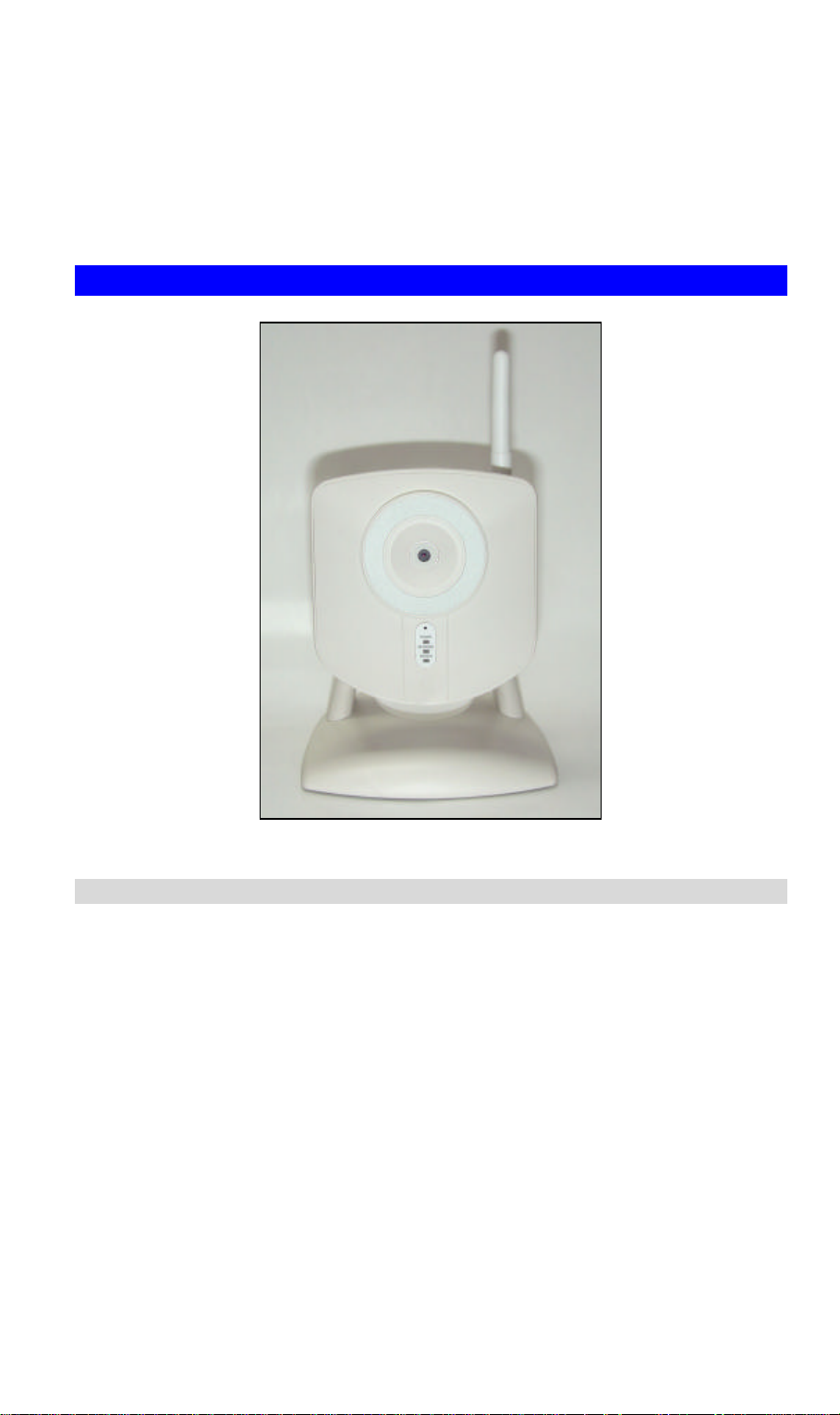
Figure 1: Wireless Network Camera
Features
• Standalone Design. The Wireless Network Camera is a standalone system with built -in
CPU and Video encoder. It requires only a power source and a connection to your LAN or
Wireless LAN.
• Suitable for Home, Business or Public Facilities. Whether for Home, Business or
Public Facility surveillance, or just for entertainment and fun, the Wireless Network
Camera has the features you need.
1
Page 6

• Multi-Protocol Support. Supporting TCP/IP networking, SMTP (E-mail), HTTP and
other Internet related pr otocols, the Wireless Network Camera can be easily integrated into
your existing network.
• Easy Configuration. A Windows-based Wizard is provided for initial setup.
Subsequent administration and management can be performed using a standard web
browser. The administrator can configure and manage the Wireless Network Camera via
the LAN or Internet.
• Viewing/Recording Utility. A user-friendly Windows utility is provided for viewing
live video. For periods when you are absent, or for scheduled recording, this application
also allows you to record video to an ASF file on your PC. The recorded files are in a
standard Windows Media format, and thus usable by a wide variety of programs if
required.
• Motion Detection. This feature can send you an E-mail when motion is detected. The
Wireless Network Camera will compare consecutive frames to detect changes caused by
the movement of large objects. This function only works indoor s due to the sensitivity of
the CMOS sensor. If desired, a short video can be included as an attachment to the E-mail.
• Flexible Scheduling. You can limit access to the video stream to specified times using
a flexible scheduling system. The Motion Detection feature can also have its own schedule,
so it is active only when required.
• Periodic Video Uploads. If desired, the Wireless Network Camera can periodically
upload a short video file to your FTP server.
• Audio Support. You can listen as well as look! Audio is included with the video if
desired. You can use either the built-in microphone or an external microphone.
Internet Features
• User-definable HTTP port number. This allows Internet Gateways to use “port
mapping” so the Wireless Network Camera and a Web Server can share the same Internet
IP address.
• DDNS Support. In order to view video over the Internet, users must know the Internet
IP address of the gateway used by the Wireless Network Camera. But if the Gateway has a
dynamic IP address, DDNS (Dynamic DNS) is required. Since many existing Gateways do
not support DDNS, this function is incorporated into the Wireless Network Camera.
• NTP (Network -Time-Protocol) Support. NTP allows the Wireless Network Camera
to calibrate its internal clock from an Internet Time-Server. This ensures that the time
stamp on Video from the Wireless Network Camera will be correct.
Security Features
• User Authentication. If desired, access to live video can be restricted to known users.
Users will have to enter their username and password before being able to view the video
stream. Up to 20 users can be entered.
• Password-Protected Configuration. Configuration data can be password protected, so
that it only be changed by the Wireless Network Camera Administrator.
Wireless Features
• Standards Compliant. The Wireless Network Camera complies with the IEEE802.11g
(DSSS) specifications for Wireless LANs.
• Supports both 802.11b and 802.11g Standards. The Wireless Network Camera
supports both 802.11b and 802.11g standards.
• Speeds to 54Mbps. All speeds up to the 802.11g maximum of 54Mbps are supported.
2
Page 7
• Wired and Wireless Net work Support. The Wireless Network Camera supports either
wired and wireless transmission.
• WEP Support. Full WEP support (64/128 Bit) on the Wireless interface is provided.
• WPA-PSK Support. The WPA-PSK (WPA1) standard is also supported, allowing
advanced encryption of wireless data.
Physical Details
Figure 2: Wireless Network Camera
Front
Lens No physical adjustment is required or possible for the lens, but you
should ensure that the lens cover remain clean. The image quality is
degraded if the lens cover is dirty or smudged.
Microphone The built-in microphone is mounted on the front. There is also a
connection for an external microphone on the rear. Connecting an
external microphone will disable the built-in microphone.
Power LED
(Green)
On - Power on.
Off - No power.
Blinking - The Ready LED will blink during start up. This will take
15 to 20 seconds.
3
Page 8

Wireless LED
(Amber)
LAN LED
(Amber)
(Wireless Network Camera only)
On - Wireless interface is active.
Off - Wireless interface is not available.
Blinking - Data is being transferred via the Wireless interface.
On - LAN port is connected to a hub or switch.
Off - LAN port is not connected.
Blinking - Data is being transmitted or received via the LAN port.
Rear
Antenna Attach the supplied antenna here. The antenna is adjustable; best
results are usually obtained with the antenna positioned vertically.
MIC In If required, an external microphone can be attached here. Attaching
a microphone here will disable the built-in microphone on the front.
Microphones designed to be used with PCs are usually compatible
with this microphone input.
Power Input Connect the supplied 5V power adapter here. Do not use other
power adapters; doing so may damage the camera.
LAN port Use a standard LAN cable to connect your Wireless Network
Camera to a 10/100BaseT hub or switch.
Note:
On the Wireless Network Camera, attaching the LAN cable will
disable the Wireless interface. Only 1 interface can be active at any
time.
Bottom
Reset Button This button is recessed; you need a pin or paper clip can be used to
depress it. It has two (2) functions, which can be activated at any
time the camera is in the "ready" mode.
• Restore Default IP Address. When pressed and released, the
Wireless Network Camera will reset its IP address to the default
value of 192.168.0.99.
• Restore Default IP Address, Administrator ID, and
Administrator password. When pressed and held or 3
seconds, the IP address, Administrator ID, and Administrator
Password settings will be set to their default values.
• IP address: 192.168.0.99
• Administrator ID: administrator
• Administrator Password: null (no password)
Note:
After this procedure is completed, the Ready LED will blink three
times to confirm that the reset was completed successfully.
4
Page 9

Package Co ntents
The following items should be included: If any of these items are damaged or missing, please
contact your dealer immediately.
1. The Wireless Network Camera
2. Installation CD -ROM
3. Quick Installation Guide
4. Power adapter
5. Camera Mount
6. Mounting Screws (for wall mounting)
7. Antenna (Wireless Network Camera only)
5
Page 10
2
Chapter 2
Basic Setup
This Chapter provides details of installing and configuring the Wireless
Network Camera.
System Requirements
• To use the LAN interface, a standard 10/100BaseT hub or switch and network cable is
required.
• To use the Wireless interface on the Wireless Network Camera, other Wireless devices
must be compliant with the IEEE802.11b or IEEE802.11g specifications. All Wireless
stations must use compatible settings.
Installation
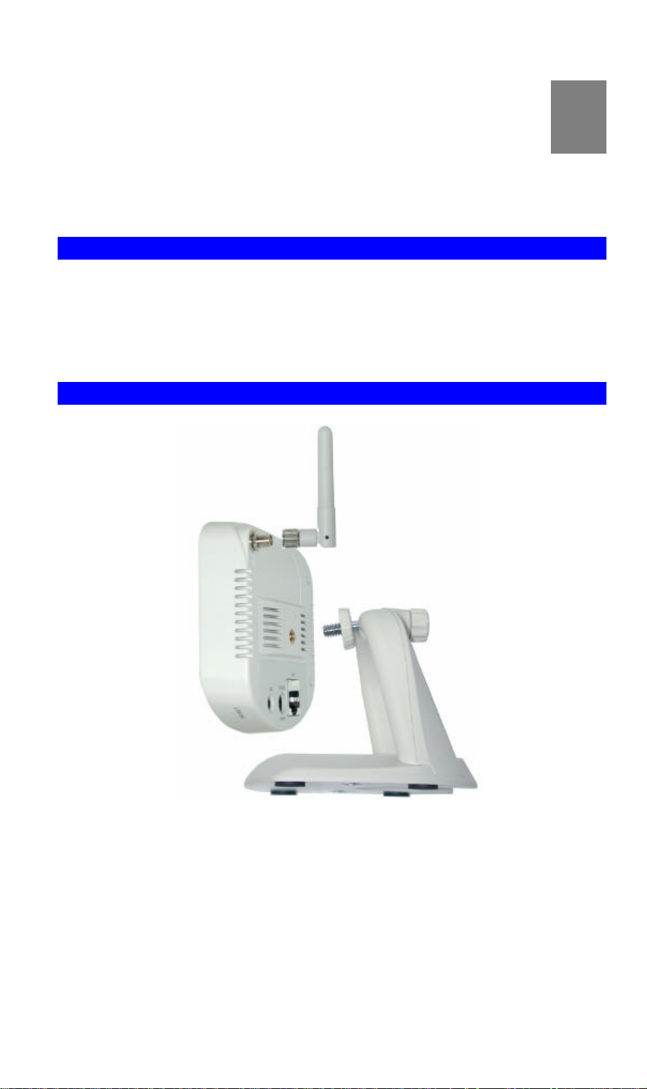
Figure 3: Camera Assembly
1. Assemble the Camera
Screw the supplied antenna to the mounting point on the rear.
Attach the Camera Mount to the camera, as shown in the diagram above.
2. Connect the LAN Cable
Connect the Wireless Network Camera to a 10/100BaseT hub or switch, using a standard
LAN cable.
6
Page 11

For the Wireless Network Camera, this disables the Wireless
Interface, because only one interface can be active. The LAN
interface is recommended for initial configuration.
The default Wireless settings for the Wireless Network Camera
are:
Mode: Infrastructure
ESSID: ANY
Wireless Security : Disabled
3. Power Up
Connect the supplied 5Vpower adapter to the Wireless Network Camera and power up.
Use only the power adapter provided. Using a different one may cause hardware damage.
4. Check the LEDs
• The Power LED will turn on briefly, then start blinking. It will blink during startup, which
takes 20 to 25 seconds.
After startup is completed, the Ready LED should remain ON.
• Either the LAN LED OR the Wireless LED should be ON.
For more information, refer to Front in Chapter 1.
7
Page 12
Setup using the Windows Wizard
Initial setup should be performed using the supplied Windows-based setup Wizard. This
program can locate the Wireless Network Camera even if its IP address is invalid for your
network. You can then configure the Wireless Network Camera with appropriate TCP/IP
settings for your LAN.
Subsequent administration can be performed with your Web browser, as explained in Chapter
3 - Web-based Administration.
Setup Procedure
1. Insert the supplied CD-ROM into your drive. If the setup program does not start
automatically, run Setup.exe in the root folder.
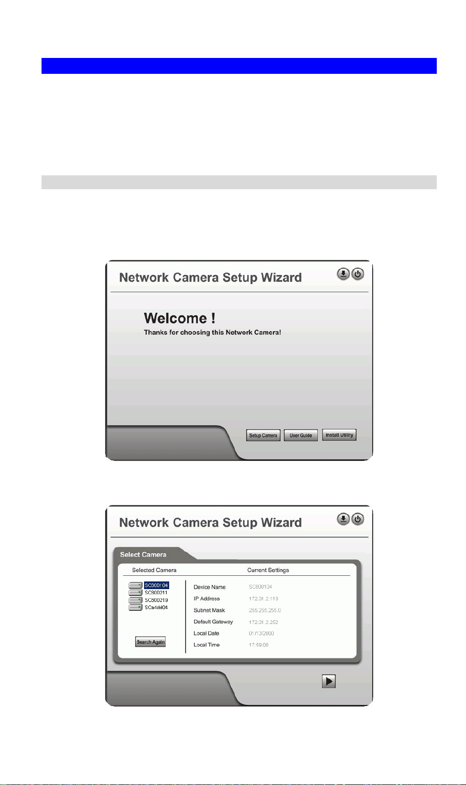
• You will see the Welcome screen shown below.
• Click the Setup Camera button to start the setup Wizard
Figure 4: Welcome Screen
2. The next screen, shown below, will list all the Wireless Network Cameras on your LAN.
Figure 5: Camera List Screen
8
Page 13
• Select the desired Camera from the list on the left. The current settings for the selected
Camera will be displayed in the table on the right.
• Click Next to continue.
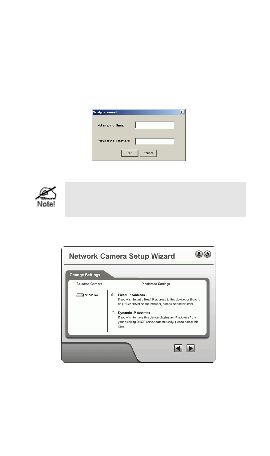
3. If the Administrator Name and Administrator Password have been set, you will be
prompted to enter them, as shown below.
• If using the default values, enter administrator for the name, and leave the
password blank.
• Otherwise, enter the Administrator Name and Administrator Password set on the User
screen.
Figure 6: Password Dialog
The Administrator Name and password can be set on the
"User" screen of the Web interface. The Web interface can be
accessed via the "Web UI" button on the final screen of the
Wizard.
4. On the following IP Address Settings screen, shown below, choose Fixed IP or Dynamic
IP.
Figure 7: Fixed or Dynamic IP Selection
• Fixed IP is recommended, and can always be used.
• Dynamic IP can only be used if your LAN has a DCHP Server.
Click Next to continue.
5. If you chose Fixed IP Address, the following TCP/IP Settings screen will be displayed.
9
Page 14

Figure 8: TCP/IP Settings
• Enter an unused IP Address from within the address range used on your LAN.
• The Subnet Mask and Default Gateway fields must match the values used by PCs on
your LAN.
• The Primary DNS address is required in order to use the E-mail alert or Dynamic
DNS features. Enter the DNS (Domain Name Server) address recommended by your
ISP.
• The Secondary DNS is optional. If provided, it will be used if the Primary DNS is
unavailable.
Click Next to continue.
6. For Wireless cameras, the following Wireless Settings screen is displayed next.
Figure 9: Wireless Settings
• Mode - If you have an Access Point, select Infrastructure. Otherwise, select Ad-hoc.
• ESSID - Enter the value used by your other Wireless devices.
• Domain - Select the domain to match your location.
10
Page 15

• Channel - For Ad-hoc mode, select the channel used by your other Wireless devices.
(For Infrastructure mode, the Access Point determines the channel used.)
7. Click Next to continue to the Security screen, shown below, choose Disabled, WEP or
WPA-PSK
Figure 10: Security Screen
8. If you chose WEP(64 or128) , the following screen is shown below.
Figure 11: WEP Key Settings
• WEP Authentication - Select the option used on your Wireless LAN.
• Keys - If using WEP, the default key must match the key used on your other Wireless
stations. The other keys are optional.
You can enter the key value directly, or generate a key by entering a string into the
Passphrase field, and clicking the Generate button.
9. If you chose the WPA-PSK option, the following screen is shown next.
11
Page 16
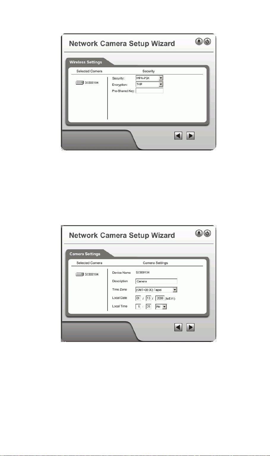
Figure 12:WPA-PSK Settings
• Encryption - Select the desired option. Wireless Stations must use the same method.
• Pre-Shared Key - Enter the key value. Data is encrypted using a key derived from the
network key. Other Wireless Stations must use the same network key. The PSK must
be from 8 to 63 characters in length.
Click Next to continue to the following screen.
10. This screen allows you to enter a suitable Description, and set the correct Time Zone,
Date, and Time. Make any desired changes, then click Next to continue.
Figure 13: Camera Settings
11. The next screen, shown below, displays all details of the Wireless Network Camera.
• Click Next if the settings are correct
• Click Back to modify any incorrect values.
12
Page 17
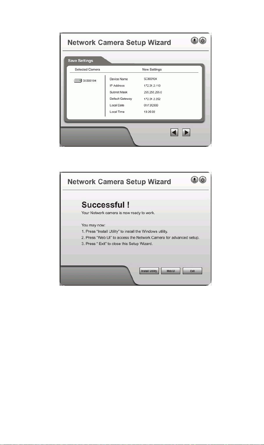
Figure 14: Save Settings
12. After clicking Next, you will see the screen below.
Figure 15: Final Screen
If desired, you can click the Web UI button to connect to the camera using your Web
Browser.
Clicking the Install Utility button will install the Viewing/Recording utility described in
Chapter 5.
13. Click Exit to end the Wizard.
Setup is now complete.
13
Page 18

3
Chapter 3
Advanced Viewing Setup
This Chapter provides information about the optional settings and features for
viewing video via the Wireless Network Camera. This Chapter is for
Administra tors only.
Introduction
After finishing setup via the Windows-based Wizard, the Wireless Network Camera can
immediately be used by all users on your LAN.
Refer to Chapter 5 - Viewing & Recording for details on viewing and recording live video.
This chapter describes some additional settings and options for viewing live Video:
• Adjusting the video image
• Controlling user access to the live video stream
• Making video available from the Internet
• Using the Motion Detection/E-mail feature
Adjusting the Video Image
If necessary, the Wireless Network Camera Administrator can adjust the Video image. Settings
are provided for:
• Image size - Select the desired size. The larger sizes require greater bandwidth.
• Image quality - This determines the degree of compression appl ied to the Video stream.
Higher quality requires greater bandwidth.
• Bandwidth/Frame Rate - You can select either of these (not both) to determine the
bandwidth required by the video stream.
• Exposure - Adjust the brightness of the image, if the Auto-Exposure does not give
satisfactory results.
• Color Balance - Select the correct color balance for your environment.
• Time Stamp - If enabled, the time will be displayed on the Video image.
• Text Overlay - If enabled, up to 20 characters can be superimposed on the Video image.
This is useful for identifying the camera.
• Audio - If desired, audio can be included in the video stream.
To Adjust the Video Image:
1. Connect to the Web-based interface of the Wireless Network Camera. (See Chapter 4 -
Web-based Management for details.)
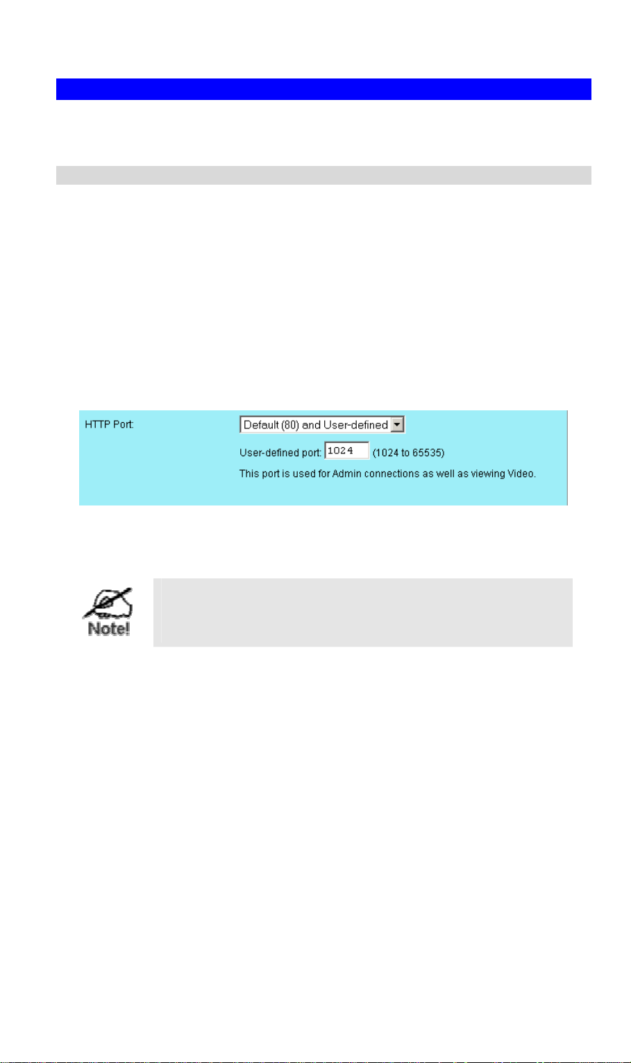
2. On the Administration menu, select Video Image. You will see a screen like the example
below.
14
Page 19
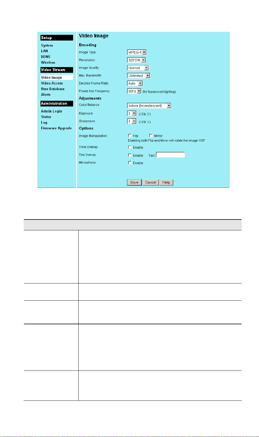
Figure 16: Video Image Screen
3. Make the required adjustments, as explained below, and save your changes.
Encoding
Image Type
Select the desired type:
• MPEG-4 gives smooth motion and high quality images, but the
video image quality will deteriorate if insufficient bandwidth is
available.
• JPEG requires more bandwidth than MPEG-4, but if the
bandwidth is insufficient, the frame rate will drop, and the
image quality will remain at the same level.
Resolution Select the desired video resolution format. The default resolution is
set to 320*240.
Image Quality Select the desired image quality. The default Image Quality is set to
Normal.
Note: Higher image quality requires more bandwidth.
Max. Bandwidth Select the desired Maximum bandwidth for the video stream. Note
that you can specify EITHER the Bandwidth OR the Frame Rate,
not both. If the Bandwidth is defined, the frame rate will be adjusted
as necessar y to achieve the specified bandwidth.
Desired Frame
Rate
The default value for bandwidth is Unlimited, which allows you to
specify the desired frame rate.
Select the desired frame rate for the camera. Reducing this will
lower the amount of bandwidth required by the camera.
Note that if you set the Bandwidth above, the Frame Rate must be
"Auto".
15
Page 20

Adjustment
Color Select the desired option to match the current environment and
lighting.
Exposure If necessary, you can adjust the exposure to obtain a better image.
For example, if the camera is facing a bright light, the image may be
too dark. In this case, you can increase the exposure.
Sharpness Select the desired option for the sharpness. You can select a
Sharpness value between -3 and 3.
Options
Image
Manipulation
The Flip setting will swap the image top-to-bottom, the Mirror
setting will swap the image left-to-right.
If the camera is mounted upside-down on the ceiling, check both the
Flip and Mirror settings to have the image rotated to the correct
position.
Time Overlay If enabled, the current time will be displayed on the Video image.
Text Overlay Enable this setting if you want text to be displayed on the Video
image, and enter the desired text - up to 20 characters. This feature
is often used to identify each camera when multiple cameras are
installed.
Microphone Enable audio recording by selecting this checkbox. Recording audio
will increase the bandwidth requirements slightly.
16
Page 21

Controlling User Access to the Video Stream
By default, all users can connect to the Wireless Network Camera and view live Video.
If desired, you can limit access to scheduled times, and also restrict access to known users.
To use these features
1. Connect to the Web-based interface of the Wireless Network Camera. (See Chapter 4 -
Web-based Management for details.)
2. On the Administration menu, select Video Access.
• To restrict the times when Video access is available, set the Access to Video Stream
setting to "Enable during Scheduled Periods" or "Disable during Scheduled Periods".
If either of these is selected, you need to use the Access Schedule button to define the
desired schedule.
• To force each user to login before viewing video, set the Viewer Authentication
setting to "Enable - Require Login".
Figure 17: Controlling User Access
• If Viewer Authentication is enabled, select User Database on the Administration
menu and create the desired users.
See Chapter 4 for further details about using the Video Access and User Database screens.
Viewing Video
• If the Video Stream is disabled, users cannot connect using either their Web Browser or
the Windows utility. However, viewing video is still possible by logging in as the
Administrator.
• When each user connects, they will be prompted for their username and password. They
must enter the name and password defined on the User Database screen.
• If using the Windows Viewing/Recording utility, the username and password can be
entered into the program, so that users do not need to provide the login data each time.
17
Page 22
Making Video available from the Internet
If your LAN is connected to the Internet, typically by a Broadband Gateway/Router and
Broadband m odem, you can make the Wireless Network Camera available via the Internet.
Wireless Network Camera Setup
The Wireless Network Camera configuration does NOT have be changed, unless:
• You wish to change the port number from the default value (1024).
• You wish to use the DDNS (Dynamic DNS) feature of the Wireless Network Camera.
HTTP Port Configuration
Normally, HTTP (Web) connections use port 80. Since the Wireless Network Camera uses
HTTP, but port 80 is likely to be used by a Web Server, you can use a different port for the
Wireless Network Camera. This port is called the User-defined Port.
The default User-defined Port is 1024. If you prefer to use a different port number, you can
specify the port number on the Wireless Network Camera's Video Access screen, as shown
below.
Figure 18: Video Access Screen
See Chapter 4 - Web-based Management for further details on using the Video Access screen.
Viewers need to know this port number in order to connect
and view live Video, so you must inform viewers of the
current port number.
DDNS (Dynamic DNS)
Many internet connections use a "Dynamic IP address", where the Internet IP address is
allocated whenever the Internet connection is established.
This means that other Internet users don't know the IP address, so can't establish a connection.
DDNS is designed to solve this problem, by allowing users to connect to your LAN using a
domain name, rather than an IP address.
To use DDNS:
1. Register for the DDNS service with a supported DDNS service provider. You can then
apply for, and be allocated, a Domain Name.
2. Enter and save the correct DDNS settings on the DDNS screen of the Wireless Network
Camera.
18
Page 23

Figure 19: DDNS Screen
3. Operation is then automatic:
• The Wireless Network Camera will then automatically contact the DDNS server
whenever it detects that the Internet IP address has changed, and inform the DDNS
server of the new IP address.
• Internet users can then connect to your LAN using the Domain Name allocated by the
DDNS service provider.
Router/Gateway Setup
Your Router or Gateway must be configured to pass incoming TCP (HTTP) connections (from
Viewers) to the Wireless Network Camera. The Router/Gateway uses the Port Number to
determine which incoming connections are intended for the Wireless Network Camera.
This feature is normally called Port Forwarding or Virtual Servers, and is illustrated below.
The Port Forwarding/Virtual Server entry tells the Router/Gateway that incoming TCP
connections on port 1024 should be passed to the Wireless Network Camera. If necessary,
check the user manual for your Router/Gateway for further details.
19
Page 24
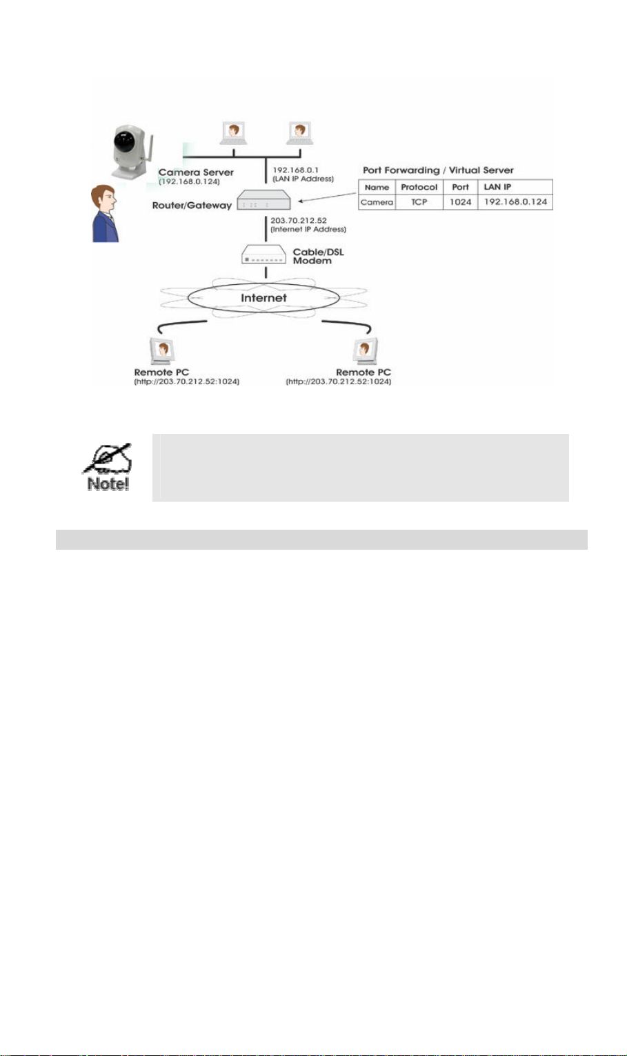
Figure 20: Connecting via the Internet
The "Port" for the Port Forwarding / Virtual Server entry
above is the "User-defined Port" number specified on the
Video Access screen of the Wireless Network Camera.
Viewing via the Internet
Clients (viewers) will also need a broadband connection; dial -up connections are NOT
recommended.
Using the Windows Viewing/Recording Utility
If using the Windows Viewing/Recording Utility, the details of the Wireless Network Camera
must be entered on the Internet tab of the Add Camera screen.
20
Page 25
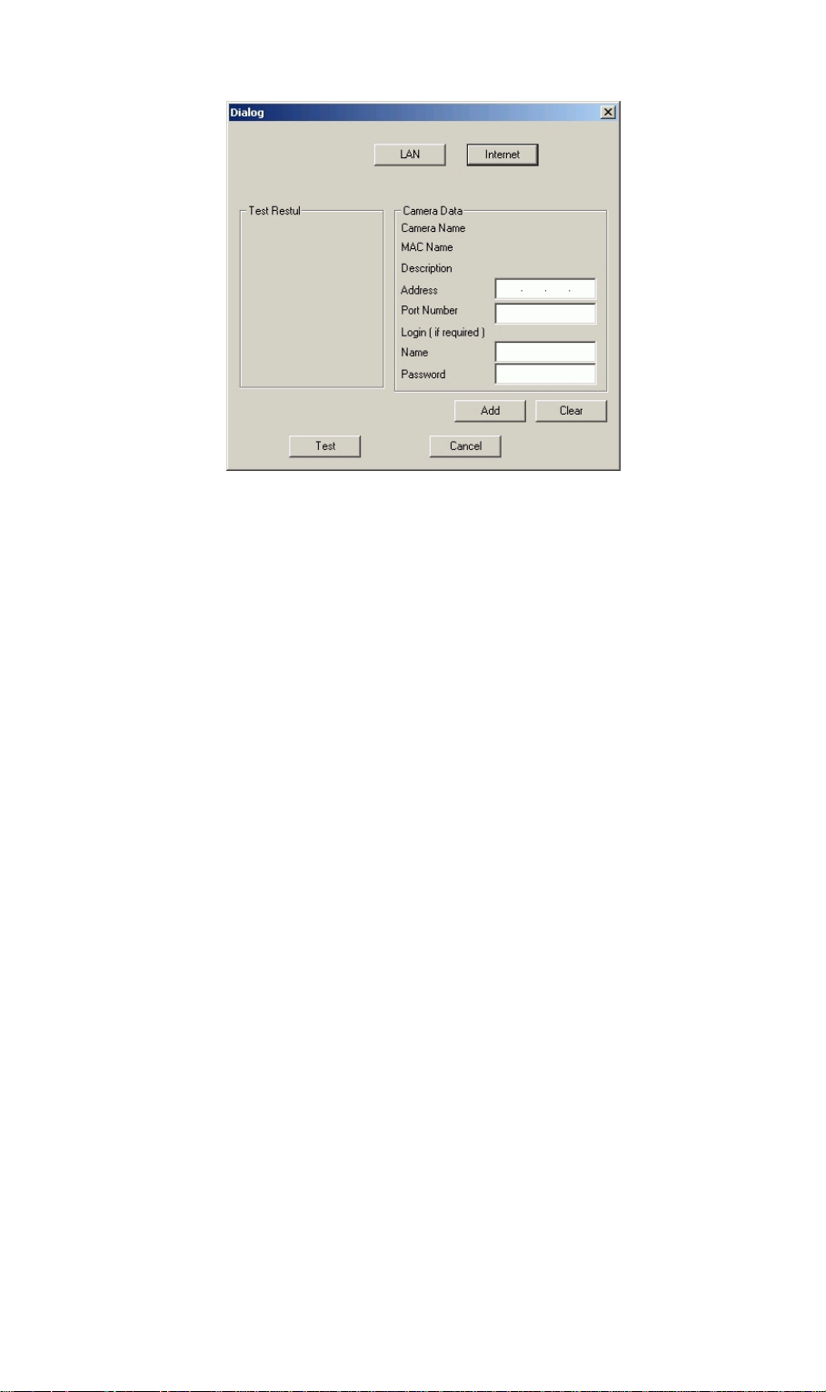
Figure 21: Add Camera from Internet
You can then select the camera in the Cameras list on the main screen, and click View to
establish a connection and view live video.
See Chapter 5 - Viewing and Recording for full details on using the Windows
Viewing/Recording utility.
Using your Web Browser
If using your Web browser, you need to know the address of the camera (either the Internet IP
address or the Domain name) and the correct port number.
Enter the address of the Wireless Network Camera, and its port number, in the Address (or
Location) field of your Browser.
Example - IP address:
HTTP://203.70.212.52:1024
Where the Router/Gateway's Internet IP address is 203.70.212.52 and the "Second Port"
number on the Wireless Network Camera is 1024.
Example - Domain Name:
HTTP://mycamera.dyndns.tv:1024
Where the Router/Gateway's Domain name is mycamera.dyndns.tv and the "Second
Port" number on the Wireless Network Camera is 1024.
See Chapter 5 -Viewing and Recording for further details of viewing Video using either the
Windows Viewing/Recording utility or your Web Browser.
21
Page 26
Motion Detection Alerts
The Motion Detection feature can generate an Alert when motion is detected.
The Wireless Network Camera will compare consecutive frames to detect changes caused by
the movement of large objects.
But the motion detector can also be triggered by:
• Sudden changes in the level of available light
• Movement of the camera itself.
Try to avoid these situations. The motion detection feature works best in locations where there
is good steady illumination, and the camera is mounted securely. It cannot be used outdoors
due to the sensitivity of the CMOS sensor.
To Use Motion Detection Alerts
Using the Web-based interface on the Wireless Network Camera, select the Alerts screen, then
configure this screen as described below.
Figure 22: Motion Detection/E-mail Alert
1. Select one of the Enable options in the Motion Detection Alerts select list.
2. Click the Area/Sensitivity button, and set the area or areas of the video image to be
examined for movement. You can define up to 4 areas, and set the motion sensitivity
individually for each area.
22
Page 27

3. If using a schedule, click the Alert Schedule button and define the desired schedule.
4. Set the desired options for the Delay between Alerts and the Video file to accompany the
Alert.
5. To have alerts sent by E -mail:
• Enable the E-Mail Alerts checkbox
• Enable and enter at least one (1) E-mail address
• Select or enter the desired options for Attachment, From and Subject fields..
• Click the SMTP Server button, and enter details of the SMTP Server used to send the
E-mail.
• In the E-mail Alerts section, select the desired options
6. To have alerts sent to your FTP Server:
• Enable the FTP Alerts checkbox
• Enter details of your FTP Server in the fields provided.
7. Save (Apply) your changes.
23
Page 28

4
Chapter 4
Web-based Management
This Chapter provides Setup details of the Wireless Network Camera’s Webbased Interface. This Chapter is for Administrators only.
Introduction
The Wireless Network Camera can be configured using your Web Browser. The Wireless
Network Camera must have an IP address which is compatible with your PC.
The recommended method to ensure this is to use the supplied Windows-based Wizard, as
described in the previous chapter.
Connecting to Wireless Network Camera
• If you have run the Windows-based setup Wizard, the final screen provided a button Web
UI. Clicking this button will immediately connect to the Wireless Network Camera, using
your Web Browser.
• If using only your Web Browser, use the following procedure to establish a connection
from your PC to the Wireless Network Camera:
• Once connected, you can add the Wireless Network Camera to your Browser's Favorites
or Bookmarks.
Connecting using your Web Browser
1. Start your WEB browser.
2. In the Address box, enter "HTTP://" and the IP Address of the Wireless Network Camera,
as in this example, which uses the Wireless Network Camera's default IP Address:
HTTP://192.168.0.99
3. If the Administrator ID and Password have been set, you will then be prompted for a
username and password. Enter the name and password you assigned.
24
Page 29

Welcome Screen
When you connect, the following screen will be displayed.
Figure 23: Welcome Screen
The menu options available from this screen are:
• Exit - Terminate the connection to the Wireless Network Camera.
• View Video - View live Video using your Web Browser.
• Administration - Access the Administration menu.
These options are explained in the following sections.
25
Page 30

View Video Screen
To view live video in your Browser, click the View Video link.
You may see a prompt regarding an "OCX" file, like the example below.
You must install this OCX file in order to view the Video.
Click "Yes" .
Figure 24 ActiveX OCX Prompt
Video will start playing automatically. There may be a delay of a few seconds while the video
stream is buffered.
26
Page 31

Administration Menu
Clicking on Administration on the menu provides access to all the settings for the Wireless
Network Camera.
The Administration menu contains the following options:
Setup
• System
• LAN
• DDNS
• Wireless
Video Stream
• Video Image
• Video Access
• Users
• Alerts
Administration
• Admin Login
• Status
• Log
• Firmware Upgrade
These options are explained in the following sections.
27
Page 32

System Screen
After clicking Administration on the main menu, or selecting System on the Administration
menu, you will see a screen like the example below.
Figure 25: System Screen
Data - System Screen
System Settings
Device Name This displays the name for the Wireless Network Camera.
Description This field is used for entering a description, such as the location of the
Wireless Network Camera.
LED Operation Enable this if you want to use this function.
Date & Time
Current Date &
Time
Timezone Choose the Timezone for your location from the drop-down list.
Network Time
Protocol
It displays the current date and time. If it's not correct, click the Change
button to modify the time settings.
If your location is currently using Daylight Saving, enable the Adjust
for daylight saving checkbox.
You must UNCHECK this checkbox when Daylight Saving
finishes .
Enable or disable the Time Server feature as required.
If Enabled, the Wireless Network Camera will contact a Network Time
Server at regular intervals and update its internal timer.
NTP Server
Address
Enter the address for the desired NTP server.
28
Page 33

Update The Schedule determines how often the Wireless Network Camera
contacts the NTP Server.
Select the desired options.
29
Page 34

LAN Screen
This screen is displayed when the LAN menu option is clicked.
Figure 26: LAN Screen
Data - LAN Screen
LAN
MAC Address It displays the current MAC address.
Obtain Address
Automatically
Fixed IP Addres s If selected, you must assign the following data to the Wireless
Obtain DNS server
address
automatically
Use the following
DNS server address
If selected, the Wireless Network Camera will obtain its IP address
and related information from a DHCP Server. Only select this
option if your LAN has a DHCP Server.
Network Camera.
• IP Address - Enter an unused IP address from the address
range used on your LAN.
• Subnet Mask - Use the same value as PCs on your LAN.
• Default Gateway - Use the same value as PCs on your LAN.
If selected, the Wireless Network Camera will obtain the DNS
server address automatically.
• Primary DNS server - Use the same value as PCs on your
LAN. Normally, your ISP will provide this address.
• Secondary DNS server - This is optional. If entered, this DNS
will be used if the Primary DNS does not respond.
30
Page 35

DDNS Screen
Many internet connections use a "Dynamic IP address", where the Internet IP address is
allocated whenever the Internet connection is established.
This means that other Internet users don't know the IP address, so can't establish a connection.
DDNS is designed to solve this problem, as follows:
• You must register for the DDNS service with a DDNS service provider. The DDNS
Service provider will allocate a Domain Name to you upon request.
• The DDNS settings on the DDNS screen above must be correct.
• The Wireless Network Camera will then contact the DDNS server whenever it detects that
the Internet IP address has changed, and inform the DDNS server of the new IP address.
(The Check WAN IP Schedule determines how often the Wireless Network Camera checks
if the Internet IP address has changed.)
This system allows other internet users to connect to you using the Domain Name allocated by
the DDNS service provider.
This screen is displayed when the DDNS menu option is clicked.
Figure 27: DDNS Screen
Data - DDNS Screen
DDNS
DDNS
Enable/Disable
Service Provider Choose a service provider from the list.
Host Name Enter the host name (Domain Name) allocated to you by the DDNS
Account Enter the login name for the DDNS account.
Enable or disable the DDNS function, as required.
Only enable this feature if you have registered for the DDNS
Service with a DDNS Server provider.
Server provider.
31
Page 36

Password Enter the password for the DDNS account.
Check WAN IP
Address
Set the schedule for checking if the Internet IP address has
changed. If the IP address has changed, the DDNS Server will be
notified.
Wireless Screen
This screen is displayed when the Wireless menu option is clicked.
Figure 28: Wireless Screen
Data - Wireless Screen
Wireless Setting (Wireless Network Camera only)
Mode The Connection Mode determines the type of wireless
communication used by the Wireless Network Camera.
• If you have an Access Point, select Infrastructure.
• Otherwise, select Ad-hoc.
SSID This must match the value used by other devices on your wireless
LAN.
Note! The SSID is case sensitive.
Domain
32
Page 37

Channel No.
• In Infrastructure mode, this setting is ignored. The Wireless
Network Camera will use the Channel set on the Access Point.
• For Ad-hoc mode, select the Channel you wish to use on your
Wireless Network Camera. Other Wireless stations should use
the same setting.
• If you experience interference (shown by lost connections
and/or slow data transfers) you may need to experiment with
different channels to see which one is the best.
Security
Security System Select the desired option, and then enter the settings for the selected
method:
• Disabled - No security is used. Anyone using the correct SSID
can connect to your network.
• WEP - The 802.11b standard. Data is encrypted before
transmission, but the encryption system is not very strong.
• WPA-PSK - Like WEP, data is encrypted before transmission.
WPA is more secure than WEP, and should be used if possible.
WPA-PSK is the version of WPA which does NOT require a
Radius Server on your LAN.
WEP
Authentication Type Normally this can be left at the default value of "Automatic." If that
fails, select the appropriate value - "Open System" or "Shared
Key." Check your wireless card's documentation to see what
method to use.
Note: In Infrastructure mode, either setting will normally work,
since most Access Points can use both methods.
WEP Encryption Select the WEP Encryption level:
• 64-bit (sometimes called 40-bit) encryption
• 128-bit encryption
WEP Keys
• Use the radio buttons to select the default key.
• Enter the key value you wish to use. Other stations must have
the same key values.
• Keys must be entered in Hex. Hex characters are the digits ( 0
~ 9 ) and the letters A ~ F.
• Click Clear Keys to set the Keys to be blank.
Passphrase Enter a word or group of printable characters in the Passphrase box
and click the "Generate Key" button to automatically configure the
WEP Key(s). If encryption strength is set to 64 bit, then each of the
four key fields will be populated with key values. If encryption
strength is set to 128 bit, then only the selected WEP key field will
be given a key value.
WPA-PSK
WPA Shared Key Enter the key value. Data is encrypted using a key derived from the
network key. Other Wireless Stations must use the same network
key. The PSK must be from 8 to 63 characters in length.
33
Page 38

Image Screen
This screen is displayed when the Image menu option is clicked.
Figure 29: Image Screen
Data - Image Screen
Encoding
Image Type
Resolution Select the desired video resolution format. The default resolution is
Image Quality Select the desired image quality. The default Image Quality is set to
Max. Bandwidth Select the desired Maximum bandwidth for the video stream. Note
Select the desired type:
• MPEG-4 gives smooth motion and high quality images, but the
video image quality will deteriorate if insufficient bandwidth is
available.
• JPEG requires more bandwidth than MPEG-4, but if the
bandwidth is insufficient, the frame rate will drop, and the
image quality will remain at the same level.
set to 320*240.
Normal.
Note: Higher image quality requires more bandwidth.
that you can specify EITHER the Bandwidth OR the Frame Rate,
not both. If the Bandwidth is defined, the frame rate will be adjusted
as necessary to achieve the specified frame rate.
The default values for bandwidth is Unlimited, which allows you to
specify the desired frame rate.
34
Page 39

Desired Frame
Rate
Select the desired frame rate for the camera. Reducing this will
lower the amount of bandwidth required by the cam era.
Power line
frequency
Adjustment
Color Select the desired option to match the current environment and
lighting.
Exposure If necessary, you can adjust the exposure to obtain a better image.
For example, if the camera is facing a bright light, the image may be
too dark. In this case, you can increase the exposure.
Sharpness Select the desired option for the sharpness. You can select a
Sharpness value between -3 and 3.
Options
Image
Manipulation
The Flip setting will swap the image top-to-bottom, the Mirror
setting will swap the image left-to-right.
If the camera is mounted upside-down on the ceiling, check both the
Flip and Mirror settings to have the image rotated to the correct
position.
Time Overlay If enabled, the current time will be displayed on the Video image.
Text Overlay Enable this setting if you want text to be displayed on the Video
image, and enter the desired text - up to 20 characters. This feature
is often used to identify each camera when multiple cameras are
installed.
Microphone Enable audio by checking this checkbox. Using Audio will increase
the bandwidth requirements slightly.
35
Page 40

Video Access Screen
This screen is displayed when the Video Access option on the Administration menu is clicked.
Figure 30: Video Access Screen
Data - Video Access Screen
Video Access
Access to Video
Stream
Access Schedule
Select the desired option:
• Enable - Camera is always enabled.
• Disable - Camera is disabled (no video stream), and will remain
disabled until you enable it.
• Enable during scheduled periods - Camera is available during
the scheduled periods, and unavailable at other times. If this
option is selected, you need to define a schedule. If no schedule
is defined, the camera is always disabled.
• Disable during scheduled periods - Camera is unavailable
during the scheduled periods, and available at other times. If
this option is selected, you need to define a schedule. If no
schedule is defined, the camera is always enabled.
Note that regardless of which setting is chosen, the Administrator
can ALWAYS access the camera and view live video.
Click this button to open a sub-window where you can define the
desired schedule.
36
Page 41

Viewer
Authentication
Select the desired option for the Viewer Authentication.
• Disable - No login required
• If selected, users do not have to provide a username and
password when they connect to the camera to view video.
• Enable - Require login
• If selected, users will be prompted for a username and password
when they connect to the camera to view video. The camera
administrator must use the "User Database" menu option to
create the desired users.
HTTP Port This sets the por t number for HTTP (Web) connections to the
Camera, whether for administration or viewing video. Select the
desired option:
• Default (port 80)
Users (and the Camera Administrator) can use port 80 only.
• Default (80) and User-defined
If you choose this option, you can connect using either port 80
or the user -defined port. You must enter the user-defined port
number (between 1024 to 65535) in the field provided
37
Page 42

Schedule Screen
This screen is displayed when the Access Schedule button on the Video Access screen is
clicked.
Figure 31: Schedule Screen
Data - Schedule
Period List This displays all periods you have entered into the database. If you
have not entered any periods, this list will be empty.
Delete Period Use the Delete Period button to remove the selected item in the list.
Add Period
Day Choose the desired option for the period.
Start Time Enter the start time using a 24 hr clock.
End Time Enter the end time using a 24 hr clock.
Add to Schedule Use this button to add a new period.
38
Page 43

User Database Screen
This screen is displayed when the User Database option on the Administration menu is clicked.
Figure 32: User Database Screen
Data - User Database Screen
Existing Users
User List This displays al l users you have entered into the User database. If
you have not entered any users, this list will be empty.
Buttons Use the Edit, Delete, Delete All buttons to manage the user database.
User Properties
User Name
User Password
Confirm Password Re-enter the password for the Administrator, to ensure it is correct.
• Enter the name for the user here. Spaces, punctuation, and
special characters must NOT be used in the name.
• The name is case insensitive (case is ignored), so you can not
have 2 names which differ only by case.
The password for the Administrator.
39
Page 44

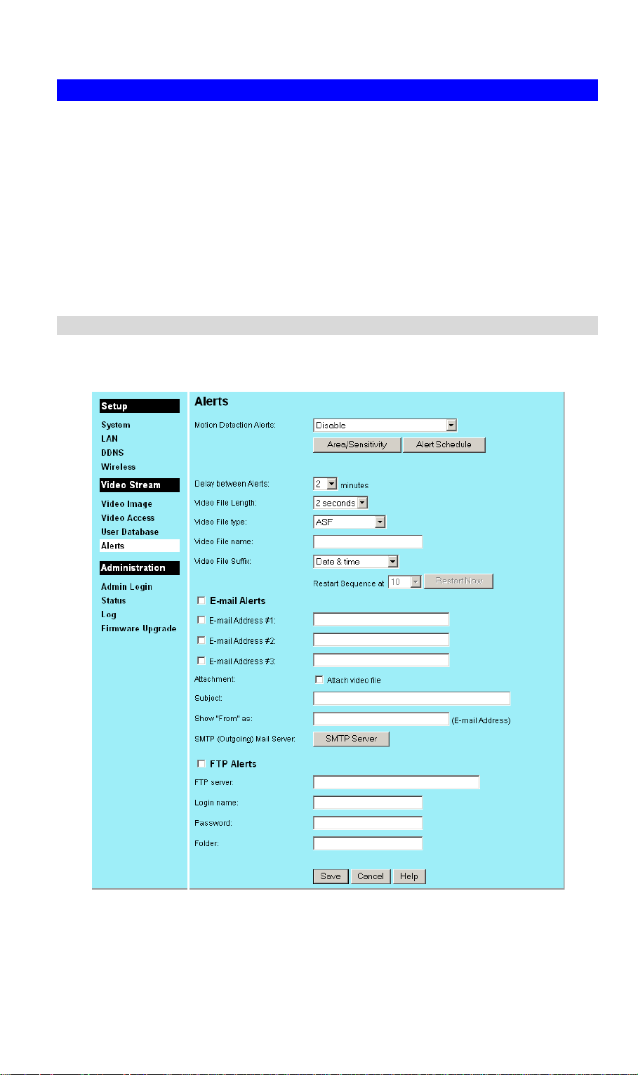
Alerts Screen
This screen is displayed when the Alerts option on the Administration menu is clicked.
.
Figure 33: Alerts Screen
40
Page 45

Data – Alerts Screen
Alerts
Motion Detection
Alerts
Area/Sensitivity
Button
Alerts can be sent when motion is detected. Select the desired
option:
• Disable - Motion detection alerts are disabled.
• Enable - Motion detection alerts are always on.
• Enable during scheduled periods - Motion detection alerts are
enabled during the scheduled periods, and disabled at other
times. Click the "Alert Schedule" button to create a suitable
schedule.
• Disable during scheduled periods - Motion detection alerts are
disabled during the scheduled periods, and enabled at other
times. Click the "Alert Schedule" button to create a suitable
schedule.
Note: If Motion Detection Alerts are enabled, you must enable and
configure either the E-mail or FTP sections in order to have an alert
sent. If neither E-mail nor FTP is enabled, the only action when
motion is detected is to record this event in the system log.
Click this button to enter the motion detection sub- screen. You can
set the area or areas of the video image to be examined, and adjust
the sensitivity of detection for each area.
Note: Motion detection can be triggered by rapid changes in
lighting condition, as well as by moving objects. For this reason, it
should only be used indoors.
Alert Schedule
Button
Delay between
Alerts
Video File Length Select the desired length. The size of the file depends on this setting,
Video File Type Select the desired type for the video file.
Video File Name Enter the name of the Video file.
Video File Suffix Select the desired option for the video file suffix.
If using a schedule, use this button to open a sub-window where you
can define a suitable schedule.
Use this to ensure your E -mail inbox or FTP Server is not flooded
with alerts. Select the desired time delay between alerts.
and also the Video size and degree of compression.
• None - the filename above is used for every file. For FTP alerts,
this will cause the previous file to be overwritten; only one file
will be available on the FTP server.
• Date & time - the date and time will be appended to the
filename above. This will ensure every file has a unique name.
• Sequence number
• This option will append a number to the specified filename. The
sequence number will eventually restart, so the filename will be
re-used. On an FTP Server, this will overwrite the previous file.
41
Page 46

Restart Sequence If using "Sequence number" for the file suffix, you can use this
setting to determine how often the sequence restarts.
Select the desired option for the Restart Sequence.
Click the Restart Now button if you wish to restart the Sequence
Number immediately.
E-Mail Alerts
Enable Check the box to enable the E-Mail Alert feature. E-mails are sent
when motion is detected.
Note:
Motion detection can be triggered by rapid changes in lighting
condition, as well as by moving objects. For this reason, it should
only be used indoors.
E-mail Address Enter at least one (1) E-Mail address; the 2nd and 3rd addresses are
optional. The E-mail alert will be sent to the E -mail address or
addresses specified here.
Attachment Enable this if you want to send a Video file as an attachment with
the E -mail alert.
Subject Enter the desired text to be shown as the "Subject" for the E-Mail
when it is received. Subject can not exceed 48 alphanumeric
characters.
Show "From" as Enter the E-mail address to be shown in the "From" field when the
E-mail is received.
SMTP(Outgoing)
Mail Server
Click the SMTP Server button to enter or modify the SMTP settings
in the resulting sub-screen.
Note: The same SMTP server is used for all E-mail operations.
FTP Alerts
FTP Alerts Use the checkbox to enable the FTP Alerts feature as required. If
enabled, you must enter details of the FTP Server.
FTP Server Enter the name or IP address of the FTP Server.
Login name Enter the Login name required to gain access to the FTP server.
Password Enter the password required to gain access to the FTP server.
Folder Enter the path to the desired folder on the FTP Server. The alert files
will be saved to this folder. Ensure the login above provides
Read/Write access to this folder.
42
Page 47

SMTP Server Screen
This screen is displayed when the SMTP Server button on the Alerts screen is clicked.
Figure 34: SMTP Screen
Data - SMTP
SMTP Server
Address
Authentication Select the desired Authentication type for the SMTP Server.
SMTP Login name Enter your login name for the SMTP Server.
SMTP Password Enter your password for the SMTP Server.
POP server name Enter the name for the POP Server.
Enter the address of the SMTP (Simple Mail Transport Protocol)
Server to be used to send E -Mail.
43
Page 48

Admin Login Screen
.
Figure 35: Admin Login Screen
Data - Admin Login Screen
Password
Administrator
Login Name
Administrator
Password
Verify Password Re-enter the password for the Administrator, to ensure it is correct.
• Enter the name for the Administrator here. Spaces, punctuation,
and special characters must NOT be used in the name.
• The name is case insensitive (case is ignored), so you can not have
2 names which differ only by case.
The password for the Administrator.
44
Page 49

Status Screen
.
Figure 36: Status Screen
Data - Status Screen
System
Device Name This shows the name of the Wireless Network Camera.
Description This shows the description of the Wireless Network Camera, such as
location.
F/W version The version of the current firmware installed.
You can upgrade the Firmware by clicking the Upgrade Firmware
button. You need to obtain the firmware upgrade file first.
Network
MAC Address The current IP address of the Wireless Network Camera.
IP Address The IP Address of the Wireless Network Camera.
Network Mask The network mask associated with the IP address above.
Gateway The IP Address of the remote Gateway associated with the IP Address
above.
Wireless (Wireless Network Camera Only)
Network Type This shows the Network Type currently in use (Ad-hoc or
Infrastructure).
SSID This displays the wireless SSID.
45
Page 50

Channel This shows the wireless channel currently used.
Security The current security setting for Wireless connections.
Video
Video Type This displays the compression type of the video stream (e.g. MPEG-4).
Resolution The image size of the video stream.
Current Viewers This shows how many viewers are currently viewing the Video stream.
Buttons
Refresh Update the log and any other data on screen.
Restart Restart (reboot) the Wireless Network Camera.
Note: This will break any existing connections. Anyone watching or
recording live video will lose their connection.
Factory Defaults Use this to restore ALL settings to their factory default values.
• Anyone watching or recording live video will lose their
connection.
• If you previously changed the IP address of the Wireless Network
Camera from its default value, this operation will change the IP
address back to the default value.
If the IP address changes, you will have to use the default IP
address to re-connect.
• The default IP address is 192.168.0.99
46
Page 51

Upgrade Firmware Screen
This screen is displayed when you click the Firmware Upgrade button on the Status screen.
Figure 37: Firmware Upgrade Screen
This screen allows you upgrade the Firmware (software) in your Wireless Network Camera.
Before using this screen, your must download the upgrade file to your PC.
Then follow this procedure:
1. Click the Browse button, and locate the upgrade file.
2. Select this file, and click OK. The filename will then appear in the Upgrade File field.
3. Click the Start Upgrade button to transfer the file to the Wireless Network Camera and
start the upgrade procedure.
Note:
• The upgrade may take several minutes.
• When the upgrade is completed, the Wireless Network Camera will restart. This will cause
any existing connections to be terminated. Any users viewing or recording the video will
see this as an error.
47
Page 52

5
Chapter 5
Viewing & Recording
This Chapter describes how to view and record the live video stream
generated by the Wireless Network Camera.
Overview
The recommended method to view video is to use the supplied Windows Viewing/Recording
utility.
Installation
1. Insert the supplied CD-ROM into your drive. If the setup program does not start
automatically, run Setup.exe in the root folder. You will see the Welcome screen shown
below.
Figure 38: Welcome Screen
2. Click the Install Utility button to start the installation of the Viewing/Recording Utility.
3. Follow the prompts to complete the installation.
48
Page 53

System Tray Icon
When started, the program will create an icon in the Windows system tray on the taskbar, as
shown below.
Figure 39: Sy stem Tray Icon
This Icon has the following functions:
• Animation - If a recording is in progress, this icon will be animated. Otherwise, it is
stationary.
• Hover - Hovering your mouse over this icon will generate a pop-up informing you of the
current status.
• Double-click - This will display the main screen, shown below.
• Right Click - This provides a menu which allows you to view program details, view the
main screen, or terminate the program.
Main Screen
When started, a screen like the example below will be displayed.
Figure 40: Main Screen
49
Page 54

Viewing Live Video
You can view live video in the main screen. The built-in software can let you view up to 16
cameras on a single computer screen at one central location.
The Icons allow you to control the cameras and video streams.
Exit - Click this to exit the program.
Shrink to task bar - Use this to minimize the program.
Play - Use this to re-start viewing, after using the Stop or Pause button.
Pause - Use this to temporarily stop the connection to the camera
Stop. This will terminate the connection to the camera, halting both the viewing
and the recording (if in progress).
Record. Click this to start recording the current video stream.
While recording, this button will be blue. To stop recording, click the Stop
button.
Snapshot Click this to take a single JPEG “snapshot” image of the current video.
You can use the “Preferences” to set the folder where these images are stored.
Zoom. This can be used to select the Audio stream which can be heard. (Only
one audio stream can be selected at any time.) If the camera does not support
audio, or if audio is disabled on the camera, this option is unavailable, and a red
“X” will cover this icon.
Flip - Click this to have the image rotated to the correct position.
Mirror - Click this to have the image rotated to the correct position.
Rotate - Click this to have the image rotated to the correct position.
Mute - This can be used to select the Audio stream which can be hear d. (Only
one audio stream can be selected at any time.) If the camera does not support
audio, or if audio is disabled on the camera, this option is unavailable, and this
icon will be displayed.
50
Page 55

Adding Cameras to the List
To add a camera to the Channel List, click the Setup button on the main screen. You will see a
screen like the example below.
Figure 41: Channel List Tab Screen
• Click the Add button.
• The Cameras on LAN panel, on the left, displays all Wireless Network Camera found on
your LAN. This list can be updated by clicking the Refresh button.
• The Camera Data panel, on the right, displays the data for the selected camera.
51
Page 56

Figure 42: Add Camera from LAN
To add a camera to the Camera List on the main screen:
1. Select a camera in the list on the left.
2. Check that the Camera Data shown on the right is correct. See below for details.
3. Click the Add button. The camera will now appear in the Channel List on the TabCamCfg
screen.
Camera Data - LAN
Camera Name This is the default name for the Wireless Network Camera, and cannot
be changed.
Address The current IP address of the Wireless Network Camera.
Port Number This will normally display "80". Only change this if requested to do so
by the Wireless Network Camera Administrator.
Login The camera Administrator can require that users provide a username and
password before being allowed to view the live video.
• If the Administrator has not enabled this option, the Login fields can
be left blank.
• Otherwise, you must enter the username and password allocated to
your by Administrator.
You can add the same Camera twice, once for the LAN (using
the LAN IP address), and again for the Internet (using the
Internet IP address). This will allow viewing the camera whether
you are on the same LAN as the camera or in a remote location.
52
Page 57

Adding Cameras on the Internet
If the Wireless Network Camera you wish to add is not on your LAN, but is available via the
Internet, click the Internet button. You will see a screen like the example below.
Figure 43: Add Camera from Internet
To add a camera to the Camera List on the main screen:
1. Enter the Camera Data on the panel on the right. See below for details.
2. Click the Test button to check that a conn ection and login can be performed successfully.
3. Click the Add button. The camera will now appear in the Channel List on the main screen.
Camera Data - Internet
Device Name This is the default name for the Wireless Network Camera, and cannot
be changed.
This field will be displayed automatically once a connection to the
Wireless Network Camera has been established.
Description This displays the description entered by the Wireless Network Camera
Administrator.
This field will be displayed automatically once a connection to the
Wireless Network Camera has been established.
Address Enter the Domain Name or Internet IP address of the desired Wireless
Network Camera.
Port Number Enter the port number used by the Wireless Network Camera. The
Wireless Network Camera Administrator can advise you of the port to
use. The default value is 1024.
Login The camera Administrator can require that users provide a username and
password before being allowed to view the live video.
• If the Administrator has not enabled this option, the Login fields can
be left blank.
• Otherwise, you must enter the username and password allocated to
your by Administrator.
53
Page 58

You can add the same Camera twice, once for the LAN, and
again for the Internet. This will allow viewing the camera
whether you are on the same LAN as the camera or in a remote
location.
54
Page 59

Recording Video
You can record Video while watching, or schedule recordings to occur when you are absent.
Recordings are stored in a standard Microsoft ASF file format, and can be played using
Microsoft Media Player.
Before doing any recording, you should review the recording settings to ensure they are
suitable for your PC.
Recording Preferences
To set the Recording Preferences, click the Setting tab on the TabCamCfg screen. You will see
a screen like the example below.
Figure 44: Recording Preferences
If necessary, change these settings to suit your environment.
Directory
Recording This is the Drive and Folder on your PC where recorded files will be
placed. You need a drive which has large amounts (Gigabytes) of free
space. Click the Browse button to select the drive and folder.
Note that file names are automatically assigned, using the date and time.
Snapshot This shows the location where snapshot images (still images, in JPEG
format) will be stored. You can use the Browse button to select the
desired drive and folder
55
Page 60

Recording Time Frame
Maximum time
frame for
Instant
This sets the maximum size of a recording which is started by clicking
the Record button on the main screen.
If the recording is not stopped manually, it will be terminated after the
time period indicated here.
Disk Allocation for Recording
Total Space It displays the total space of the disk.
Available Space It displays the available space of the disk.
Enable
Enable this if you want to use this feature.
Diskspace limit
Used Space It displays the used space of the disk.
Maximum Enter the value for the maximum space for recording.
Overwrite
oldest file
The utility will overwrite the old files if the space is not enough for
recording.
Stop Recording It will stop recording if the space is not enough.
Start Info
Launch Viewer
Check this to have this utility start when Windows starts.
Recorder...
Auto start
video...
Check this if you wish to have the utility connect to the specified
cameras as soon as the utility starts.
56
Page 61

Live Recordings
You can start and stop recording from the Main screen, using the controls provided.
Exit - Click this to exit the program.
Shrink to task bar - Use this to minimize the program.
Play - Use this to re-start viewing, after using the Stop or Pause button.
Pause - Use this to temporarily stop the connection to the camera
Stop. This will terminate the connection to the camera, halting both the viewing
and the recording (if in progress).
Record. Click this to start recording the current video stream.
While recording, this button will be blue. To stop recording, click the Stop
button.
Snapshot Click this to take a single JPEG “snapshot” image of the current video.
You can use the “Preferences” to set the folder where these images are stored.
Zoom. This can be used to select the Audio stream which can be heard. (Only
one audio stream can be selected at any time.) If the camera does not support
audio, or if audio is disabled on the camera, this option is unavailable, and a red
“X” will cover this icon.
Flip - Click this to have the image rotated to the correct position.
Mirror - Click this to have the image rotated to the correct position.
Rotate - Click this to have the image rotated to the correct position.
Mute - This can be used to select the Audio stream which can be heard. (Only
one audio stream can be selected at any time.) If the camera does not support
audio, or if audio is disabled on the camera, this option is unavailable, and this
icon will be displayed.
57
Page 62

Scheduled Recordings
Recordings can be scheduled at any time, for any known Wireless Network Camera. (Of course,
your PC must be ON at the scheduled time.)
To use this feature, click the Scheduled Recording button under the Channel List tab. You
will see a screen like the example below.
Figure 45: Scheduled Recording List
This screen lists all scheduled recordings. For each recording, the following data is shown:
• Type - Indicates if the recording is One Time, Everyday, or on a particular day each week.
• Start Date - The date the recording will be made. If the recording schedule is repetitive,
this is the date of the next recording.
• Start Time - The time the recording will be made.
• Duration - Indicates the duration of the recording.
If a scheduled recording is selected, the Delete button can be used to delete the selected entry.
Data - Schedule Definition
Camera Select the camera to be used. If the desired camera is not listed, you
must define by using the Add button on the screen.
Cycle Select the desired option:
• One Time - Only one (1) recording is made, on the specified date,
at the specified time.
• Everyday - The recording is made every day, at the specified time.
The Start Day indicates when the first recording will be made.
• Mon ~ Fri - The recording is made from Monday through Friday
each week. The Start Day indicates when the first recording will be
made.
• Sat ~ Sun - The recording is ma de from Saturday through Sunday
58
Page 63

each week. The Start Day indicates when the first recording will be
made.
• Every Sunday, Every Monday, … - The recording is made on the
specified day each week. The Start Day indicates when the schedule
becomes active.
Start Date Select the desired date.
• For a single recording, this is the day the recording will be made.
• For daily (Everyday) recordings, this is the starting date.
• For weekly recordings, this determines when the schedule becomes
active.
Start Time Select the desired start time.
Duration Enter or select the desired duration of the recording.
59
Page 64

Viewing with your Web Browser
The recommended method to view live video from the Wireless Network Camera is to use the
Windows utility.
However, you can also use your Web browser if necessary.
Viewing over your LAN
To establish a connection from your PC to the Wireless Network Camera:
1. Start your WEB browser.
2. In the Address box, enter "HTTP://" and the IP Address of the Wireless Network Camera,
as in this example, which uses the Wireless Network Camera's default IP Address:
HTTP://192.168.0.99
3. If the Administrator has enabled the user security feature, you will then be prompted for a
username and password.
Enter the name and password assigned to you by the Wireless Netw ork Camera
administrator.
4. When you connect, the following screen will be displayed.
Figure 46: Home Screen
5. Click View Video to see a screen like the example below.
60
Page 65

Figure 47: View Video Screen
• If using Internet Explorer on Windows, you may see a prompt regarding an "OCX" file,
like the example below.
You must install this OCX file in order to view the Video. Click "Yes".
Figure 48 ActiveX OCX Prompt
• Video will start playing automatically. There may be a delay of a few seconds while the
video stream is buffered.
61
Page 66

Viewing via the Internet
If the LAN with the Wireless Network Camera is connected to the Internet, and configured
correctly, you can connect to the Wireless Network Camera via the Internet.
See Making Video available from the Internet in Chapter 3 for details of the required LAN
configuration.
To establish a connection from your PC to the Wireless Network Camera via the Internet:
1. Obtain the Internet address and port number of the Wireless Network Camera from the
Administrator.
2. Start your WEB browser.
3. In the Address box, enter the following:
HTTP://Internet_Address:port_number
Example using an IP address:
HTTP://203.70.212.52:1024
Where the Router/Gateway's Internet IP address is 203.70.212.52 and the "Second
Port" number on the Wireless Network Camera is 1024.
Example using a Domain Name:
HTTP://mycamera.dyndns.tv:1024
Where the Router/Gateway's Internet Domain name (using DDNS in this example) is
mycamera.dyndns.tv and the "Second Port" number on the Wireless Network
Camera is 1024.
4. If the Administrator has enabled the user validation feature, you will then be prompted for
a username and password.
Enter the name and password assigned to you by the Wireless Network Camera
administrator.
5. When you connect, the following screen will be displayed.
Figure 49: Home Screen
62
Page 67

6. Click View Video to see a screen like the example below.
Figure 50: View Video Screen
• If using Internet Explorer on Windows, you may see a prompt regarding an "OCX" file,
like the example below.
You must install this OCX file in order to view the Video. Click "Yes".
Figure 51 ActiveX OCX Prompt
• Video will start playing automatically. There may be a delay of a few seconds while the
video stream is buffered.
Note:
Viewers need a broadband Internet connection to view video effectively. Dial-up connections
are NOT recommended.
63
Page 68

6
Chapter 6
Troubleshooting
This chapter covers the most likely problems and their solutions.
Overview
This chapter covers some common problems that may be encountered while using the Wireless
Network Camera and some possible solutions to them. If you follow the suggested steps and
the Wireless Network Camera still does not function properly, contact your dealer for further
advice.
Problems
Problem 1:
Solution 1: It is possible that your PC's IP address is not compatible with the IP
Problem 2:
Solution 2: Check the following:
I can't connect to the Wireless Network Camera with my Web
Browser to configure it.
address of the Wireless Network Camera.
Use the Windows utility to configure the Wireless Network Camera with a
valid IP address.
The Windows utility doesn't list any Wireless Network Cameras.
• The Wireless Network Camera is installed, LAN connections are OK,
it is powered ON and startup is complete.
• Ensure that your PC and the Wireless Network Camera are on the
same network segment. (If you don't have a router, this must be the
case.)
• Ensure that your PC has the TCP/IP network protocol loaded. In
Windows, this is done by using Control Panel-Network. If an entry for
TCP/IP -> Network card is not listed, use Add - Protocol - Microsoft -
TCP/IP to add it.
You then need to select the new entry (TCP/IP -> Network card), click
Properties, and configure the IP Address tab.
• If your LAN has a DHCP
Server, you can select "Obtain an IP Address automatically".
• Otherwise, you must
select "Specify an IP Address", and enter values for IP Address,
Subnet Mask, and Gateway. All devices on your LAN must use
compatible values. Remember that each device needs a unique IP
Address, and the same Subnet Mask.
Problem 3
Solution 3 You SHOULD be prompted for a user name and password if trying to
When I try to connect to the Wireless Network Camera, I get
prompted for a user name and password.
access the Administration menu.
Enter the Administrator ID and Password set on the User screen.
64
Page 69

If you are just trying to view Video, the User Name/Password prompt
indicates that the Administrator has restricted access to specified users.
Ask the Administrator for your User Name and Password.
Problem 4
Solution 4
Problem 5
Solution 5
Problem 6
Solution 6
I can't connect to the Wireless Network Camera using a Wireless
connection.
1) If a LAN cable is connected to the LAN port, the Wireless interface is
disabled. Only one interface can be active.
2) Check that your PC and the Wireless Network Camera have compatible
Wireless settings.
• Mode (Infrastructure or Ad-hoc) must be correct.
• ESSID must match.
• WEP settings must match.
• In Ad-hoc mode, the Channel should match, although this is often not
required.
Video quality may suddenly deteriorate.
This can happen when an additional viewer connects to the Wireless
Network Camera, overloading the camera or the available bandwidth. The
image size and quality can be adjusted to cater for the required number of
viewers and the available bandwidth.
The motion detection feature doesn't send me any E-mails.
It may be that the SMTP (Simple Mail Transport Protocol) server used by
the Wireless Network Camera to send the E-mail will not accept mail from
the Wireless Network Camera. Try using a different SMTP server. The
Wireless Network Camera derives the address of the SMTP server from
the E -mail address you enter in the Show "From" as: field.
Problem 7
Solution 7
Problem 8
Solution 8
Using the motion detection feature, I receive E-mails which don't show
any moving objects.
The motion detection feature doesn't actually detect motion. It compares
frames to see if they are different. Major differences between frames are
assumed to be caused by moving objects.
But the motion detector can also be triggered by:
• Sudden changes in the level of available light
• Movement of the camera itself.
Try to avoid these situations. The motion detection feature works best in
locations where there is good steady illumination, and the camera is
mounted securely. This feature can NOT be used if the camera is outdoors.
The image is blurry.
Try cleaning the lens, and adjusting the focus ring.
65
Page 70

A
Appendix A
Specifications
Wireless Network Camera
Model Wireless Network Camera
Dimensions 164 mm (L) * 88 mm (W)* 54 mm (H)
6.4 inch (L) * 3.5 inch (W) * 2.1 inch (H)
Operating Temper ature
Storage Temperature
Network Protocols: TCP/IP, DHCP, SMTP, NTP, HTTP
Network Interface: 1 Ethernet 10/100BaseT (RJ45) LAN connection
Wireless interface IEEE 802.11b/802.11g compatible, Infrastructure/Ad-hoc mode,
LEDs 3
Power Adapter 5V DC External
0° C to 40° C
-10° C to 70° C
WEP/WPA-PSK security support, roaming support
66
Page 71

Regulatory Approvals
CE Approvals
The Wireless Network Camera and the Ethernet Network Camera meet the guidelines of the
European Union and comply with the 99/5/EEC and RTTE 99/5EG directives, including the
following standards:
• EN60950
• EN300 328-2
• EN301 489-1
• EN301 489-17
This is a Class B product. In a domestic environment this product may cause radio interference
in which case the user may be required to take adequate measures .
67
Page 72

Copyright Notice
Many software components are covered by the GNU GPL (General Public License). Some are
covered by other Licenses as listed in the table below.
Details of each applicable license are contained in the following section.
No Warranty
THIS SOFTWARE IS PROVIDED BY THE AUTHOR AND CONTRIBUTORS ``AS IS''
AND ANY EXPRESS OR IMPLIED WARRANTIES, INCLUDING, BUT NOT LIMITED
TO, THE IMPLIED WARRANTIES OF MERCHANTABILITY AND FITNESS FOR A
PARTICULAR PURPOSE ARE DISCLAIMED. IN NO EVENT SHALL THE AUTHOR
OR CONTRIBUTORS BE LIABLE FOR ANY DIRECT, INDIRECT, INCIDENTAL,
SPECIAL, EXEMPLARY, OR CONSEQUENTIAL DAMAGES (INCLUDING, BUT NOT
LIMITED TO, PROCUREMENT OF SUBSTITUTE GOODS OR SERVICES; LOSS OF
USE, DATA, OR PROFITS; OR BUSINESS INTERRUPTION) HOWEVER CAUSED AND
ON ANY THEORY OF LIABILITY, WHETHER IN CONTRACT, STRICT LIABILITY, OR
TORT (INCLUDING NEGLIGENCE OR OTHERWISE) ARISING IN ANY WAY OUT OF
THE USE OF THIS SOFTWARE, EVEN IF ADVISED OF THE POSSIBILITY OF SUCH
DAMAGE.
Network Camera copyright information
Package source codes License
rrload GPL
uClinux-2.4.19.uc1
busybox-0.60.3
tinylogin-1.02
inetutils-1.3.2
thttpd-2.20b-rr
uClibc-0.9.5 LGPL
Lan driver (DM9000)
cgi-lib
Cgihtml
Ntp-4.1.0-4.src.rpm GPL
Cron-small version
Dhcpcd-1.3.22-p11
Smtpclient-1.0.0
Upnpsdk-1.0.4
ez-ipupdate-3.0.11b7
GPL
GPL
GPL
GPL
See following
GPL
Copyright cgi-LIB
Free SW
GPL
GPL
GPL
GPL
GPL
68
Page 73

thttpd License
Copyright 1995,1998,1999,2000 by Jef Poskanzer <jef@acme.com>. All rights reserved.
Redistribution and use in source and binary forms, with or without modification, are permitted
provided that the following conditions are met:
1. Redistributions of source code must retain the above copyright notice, this list of conditions
and the following disclaimer.
2. Redistributions in binary form must reproduce the above copyright notice, this list of
conditions and the following disclaimer in the documentation and/or other materials provided
with the distribution.
THIS SOFTWARE IS PROVIDED BY THE AUTHOR AND CONTRIBUTORS ``AS IS''
AND ANY EXPRESS OR IMPLIED WARRANTIES, INCLUDING, BUT NOT LIMITED
TO, THE IMPLIED WARRANTIES OF MERCHANTABILITY AND FITNESS FOR A
PARTICULAR PURPOSE ARE DISCLAIMED. IN NO EVENT SHALL THE AUTHOR
OR CONTRIBUTORS BE LIABLE FOR ANY DIRECT, INDIRECT, I NCIDENTAL,
SPECIAL, EXEMPLARY, OR CONSEQUENTIAL DAMAGES (INCLUDING, BUT NOT
LIMITED TO, PROCUREMENT OF SUBSTITUTE GOODS OR SERVICES; LOSS OF
USE, DATA, OR PROFITS; OR BUSINESS INTERRUPTION) HOWEVER CAUSED AND
ON ANY THEORY OF LIABILITY, WHETHER IN CONTRACT , STRICT LIABILITY, OR
TORT (INCLUDING NEGLIGENCE OR OTHERWISE) ARISING IN ANY WAY OUT OF
THE USE OF THIS SOFTWARE, EVEN IF ADVISED OF THE POSSIBILITY OF SUCH
DAMAGE.
69
Page 74

cgi-LIB Copyright Notice
Author: Noel V Aguilar
Version: 1.4
Filename: cgi -lib.h
Program Library: CGI -LIB
Feel free to use, copy, reference, or modify this program in any way.
Support public domain freeware.
For updates or to report bugs go to my home page
http://www.geocities.com/SiliconValley/Vista/6493/
The web page for the library is:
http://www.geocities.com/SiliconValley/Vista/6493/cgi-lib.html
Disclaimer
THE INFORMATION, CODE AND EXECUTABLE PROVIDED ARE PROVIDED "AS IS"
WITHOUT WARRANTY OF ANY KIND, EITHER EXPRESS OR IMPLIED, INCLUDING
BUT NOT LIMITED TO THE IMPLIED WARRANTIES OF MERCHANTABILITY AND
FITNESS FOR A PARTICULAR PURPOSE. IN NO EVENT SHALL NOEL V AGUILAR
BE LIABLE FOR ANY DAMAGES WHATSOEVER INCLUDING DIRECT, INDIRECT,
INCIDENTAL, CONSEQUENTIAL, LOSS OF BUSINESS PROFITS OR SPECIAL
DAMAGES. ALL THE INFORMATION, CODE AND EXECUTABLES ARE FOR
EDUCATIONAL PURPOSES ONLY.
70
Page 75

GNU General Public License
GNU GENERAL PUBLIC LICENSE
Version 2, June 1991
Copyright (C) 1989, 1991 Free Software Foundation, Inc.
59 Temple Place, Suite 330, Boston, MA 02111-1307 USA
Everyone is permitted to copy and distribute verbatim copies of this license document, but
changing it is not allowed.
Preamble
The licenses for most software are designed to take away your freedom to share and change it.
By contrast, the GNU General Public License is intended to guarantee your freedom to share
and change free software--to make sure the software is free for all its users. This General
Public License applies to most of the Free Software Foundation's software and to any other
program whose authors commit to using it. (Some other Free Software Foundation software is
covered by the GNU Library General Public License instead.) You can apply it to your
programs, too.
When we speak of free software, we are referring to freedom, not price. Our General Public
Licenses are designed to make sure that you have the freedom to distribute copies of free
software (and charge for this service if you wish), that you receive source code or can get it if
you want it, that you can change the sof tware or use pieces of it in new free programs; and that
you know you can do these things.
To protect your rights, we need to make restrictions that forbid anyone to deny you these rights
or to ask you to surrender the rights. These restrictions translate to certain responsibilities for
you if you distribute copies of the software, or if you modify it.
For example, if you distribute copies of such a program, whether gratis or for a fee, you must
give the recipients all the rights that you have. You must make sure that they, too, receive or
can get the source code. And you must show them these terms so they know their rights.
We protect your rights with two steps: (1) copyright the software, and (2) offer you this license
which gives you legal permission to copy, distribute and/or modify the software.
Also, for each author's protection and ours, we want to make certain that everyone understands
that there is no warranty for this free software. If the software is modified by someone else and
passed on, we want its recipients to know that what they have is not the original, so that any
problems introduced by others will not reflect on the original authors' reputations.
Finally, any free program is threatened constantly by software patents. We wish to avoid the
danger that redistributors of a free program will individually obtain patent licenses, in effect
making the program proprietary. To prevent this, we have made it clear that any patent must
be licensed for everyone's free use or not licensed at all. The precise terms and conditions for
copying, distribution and modification follow.
GNU GENERAL PUBLIC LICENSE
Terms And Conditions For Copying, Distribution And Modification
0. This License applies to any program or other work which contains a notice placed by the
copyright holder sa ying it may be distributed under the terms of this General Public License.
The "Program", below, refers to any such program or work, and a "work based on the
Program" means either the Program or any derivative work under copyright law: that is to say,
a work containing the Program or a portion of it, either verbatim or with modifications and/or
71
Page 76

translated into another language. (Hereinafter, translation is included without limitation in the
term "modification".) Each licensee is addressed as "you".
Activities other than copying, distribution and modification are not covered by this License;
they are outside its scope. The act of running the Program is not restricted, and the output from
the Program is covered only if its contents constitute a work based on the Program
(independent of having been made by running the Program). Whether that is true depends on
what the Program does.
1. You may copy and distribute verbatim copies of the Program's source code as you receive it,
in any medium, provided that you conspicuously and appropriately publish on each copy an
appropriate copyright notice and di sclaimer of warranty; keep intact all the notices that refer to
this License and to the absence of any warranty; and give any other recipients of the Program a
copy of this License along with the Program.
You may charge a fee for the physical act of transferring a copy, and you may at your option
offer warranty protection in exchange for a fee.
2. You may modify your copy or copies of the Program or any portion of it, thus forming a
work based on the Program, and copy and distribute such modifications or work under the
terms of Section 1 above, provided that you also meet all of these conditions:
a) You must cause the modified files to carry prominent notices stating that you changed the
files and the date of any change.
b) You must cause any work that you distribute or publish, that in whole or in part contains or
is derived from the Program or any part thereof, to be licensed as a whole at no charge to all
third parties under the terms of this L icense.
c) If the modified program normally reads commands interactively when run, you must cause it,
when started running for such interactive use in the most ordinary way, to print or display an
announcement including an appr opriate copyright notice and a notice that there is no warranty
(or else, saying that you provide a warranty) and that users may redistribute the program under
these conditions, and telling the user how to view a copy of this License. (E xception: if the
Program itself is interactive but does not normally print such an announcement, your work
based on the Program is not required to print an announcement.)
These requirements apply to the modified work as a whole. If identifiable sections of that
work are not derived from the Program, and can be reasonably considered independent and
separate works in them selves, then this License, and its terms, do not apply to those sections
when you distribute them as separate works. But when you distribute the same sections as part
of a whole which is a work based on the Program, the distribution of the whole must be on the
terms of this License, whose permissions for other licensees extend to the entire whole, and
thus to each and every part regardless of who wrote it. Thus, it is not the intent of this section
to claim rights or contest your rights to work written entirely by you; rather, the intent is to
exercise the right to control the distribution of derivative or collective works based on the
Program.
In addi tion, mere aggregation of another work not based on the Program with the Program (or
with a work based on the Program) on a volume of a storage or distribution medium does not
bring the other work under the scope of this License.
3. You may copy and distribute the Program (or a work based on it, under Section 2) in object
code or executable form under the terms of Sections 1 and 2 above provided that you also do
one of the following:
72
Page 77

a) Accompany it with the complete corresponding machine-readable source code, which must
be distributed under the terms of Sections 1 and 2 above on a medium customarily used for
software interchange; or,
b) Accompany it with a written offer, valid for at least three years, to give any third party, for a
charge no more than your cost of physically performing source distribution, a complete
m achine-readable copy of the corresponding source code, to be distributed under the terms of
Sections 1 and 2 above on a medium customarily used for software interchange; or,
c) Accompany it with the information you received as to the offer to distribute corresponding
source code. (This alternative is allowed only for noncommercial distribution and only if you
received the program in object code or executable form with such an offer, in accord with
Subsection b above.)
The source code for a work means the preferred form of the work for making modifications to
it. For an executable work, complete source code means all the source code for all modules it
contains, plus any associated interface definition files, plus the scripts used to control
compilation and installation of the executable. However, as a special exception, the source
code distributed need not include anything that is normally distributed (in either source or
binary form) with the major components (compiler, kernel, and so on) of the operating system
on which the executable runs, unless that component itself accompanies the executable.
If distribution of executable or object code is made by offering access to copy from a
designated place, then offering equivalent access to copy the source code from the same place
counts as distribution of the source code, even though third parties are not compelled to copy
the source along with the object code.
4. You may not copy, modify, sublicense, or distribute the Program except as expressly
provided under this License. Any attempt otherwise to copy, modify, sublicense or distribute
the Program is void, and will automatically terminate your rights under this License. However,
parties who have received copies, or rights, from you under this License will not have their
licenses terminated so long as such parties remain in full compliance.
5. You are not required to accept this License, since you have not signed it. However, nothing
else grants you permission to modify or distribute the Program or its derivative works. These
actions are prohibited by law if you do not accept this License. Therefore, by modifying or
distributing the Program (or any work based on the Program), you indicate your acceptance of
this License to do so, and all its terms and conditions for copying, distributing or modifying the
Program or works based on it.
6. Each time you redistribute the Program (or any work based on the Program), the recipient
automatically receives a license from the original licensor to copy, distribute or modify the
Program subject to these terms and conditions. You may not impose any further restrictions on
the recipients' exercise of the rights granted herein. You are not responsible for enforcing
compliance by third parties to this License.
7. If, as a consequence of a court judgment or allegation of patent infringement or for any
other reason (not limited to patent issues), conditions are imposed on you (whether by court
order, agreement or otherwise) that contradict the conditions of this License, they do not
excuse you from the conditions of this License. If you cannot distribute so as to satisfy
simultaneously your obligations under this License and any other pertinent obligati ons, then as
a consequence you may not distribute the Program at all. For example, if a patent license
would not permit royalty-free redistribution of the Program by all those who receive copies
73
Page 78

directly or indirectly through you, then the only way you could satisfy both it and this License
would be to refrain entirely from distribution of the Program.
If any portion of this section is held invalid or unenforceable under any particular circumstance,
the balance of the section is intended to apply and the section as a whole is intended to apply in
other circumstances.
It is not the purpose of this section to induce you to infringe any patents or other property right
claims or to contest validity of any such claims; this section has the sole purpose of protecting
the integrity of the free software distribution system, which is implemented by public license
practices. Many people have made generous contributions to the wide range of software
distributed through that system in reliance on consistent applicati on of that system; it is up to
the author/donor to decide if he or she is willing to distribute software through any other
system and a licensee cannot impose that choice.
This section is intended to make thoroughly clear what is believed to be a consequence of the
rest of this License.
8. If the distribution and/or use of the Program is restricted in certain countries either by
patents or by copyrighted interfaces, the original copyright holder who places the Program
under this License may add an explicit geographical distribution limitation excluding those
countries, so that distribution is permitted only in or among countries not thus excluded. In
such case, this License incorporates the limitation as if written in the body of this License.
9. The Free Software Foundation may publish revised and/or new versions of the General
Public License from time to time. Such new versions will be similar in spirit to the present
version, but may differ in detail to address new problems or concerns.
Each version is given a distinguishing version number. If the Program specifies a version
number of this License which applies to it and "any later version", you have the option of
following the terms and conditions either of that version or of any later version publ ished by
the Free Software Foundation. If the Program does not specify a version number of this
License, you may choose any version ever published by the Free Software Foundation.
10. If you wish to incorporate parts of the Program into other free programs whose distribution
conditions are different, write to the author to ask for permission. For software which is
copyrighted by the Free Software Foundation, write to the Free Software Foundation; we
sometimes make exceptions for this. Our decision will be guided by the two goals of
preserving the free status of all derivatives of our free software and of promoting the sharing
and reuse of software generally.
NO WARRANTY
11. BECAUSE THE PROGRAM IS LICENSED FREE OF CHARGE, THERE IS NO
WARRANTY FOR THE PROGRAM, TO THE EXTENT PERMITTED BY APPLICABLE
LAW. EXCEPT WHEN OTHERWISE STATED IN WRITING THE COPYRIGHT
HOLDERS AND/OR OTHER PARTIES PROVIDE THE PROGRAM "AS IS" WITHOUT
WARRANTY OF ANY KIND, EITHER EXPRESSED OR IMPLIED, INCLUDING, BUT
NOT LIMITED TO, THE IMPLIED WARRANTIES OF MERCHANTABILITY AND
FITNESS FOR A PARTICULAR PURPOSE. THE ENTIRE RISK AS TO THE QUALITY
74
Page 79

AND PERFORMANCE OF THE PROGRAM IS WITH YOU. SHOULD THE PROGRAM
PROVE DEFECTIVE, YOU ASSUME THE COST OF ALL NECESSARY SERVICING,
REPAIR OR CORRECTION.
12. IN NO EVENT UNLESS REQUIRED BY APPLICABLE LAW OR AGREED TO IN
WRITING WILL ANY COPYRIGHT HOLDER, OR ANY OTHER PARTY WHO MAY
MODIFY AND/OR REDISTRIBUTE THE PROGRAM AS PERMITTED ABOVE, BE
LIABLE TO YOU FOR DAMAGES, INCLUDING ANY GENERAL, SPECIAL,
INCIDENTAL OR CONSEQUENTIAL DAMAGES ARISING OUT OF THE USE OR
INABILITY TO USE THE PROGRAM (INCLUDING BUT NOT LIMITED TO LOSS OF
DATA OR DATA BEING RENDERED INACCURATE OR LOSSES SUSTAINED BY
YOU OR THIRD PARTIES OR A FAILURE OF THE PROGRAM TO OPERATE WITH
ANY OTHER PROGRAMS), EVEN IF SUCH HOLDER OR OTHER PARTY HAS BEEN
ADVISED OF THE POSSIBILITY OF SUCH DAMAGES.
END OF TERMS AND CONDITIONS
75
Page 80

Lesser GNU General Public License
GNU LESSER GENERAL PUBLIC LICENSE
Version 2.1, February 1999
Copyright (C) 1991, 1999 Free Software Foundation, Inc.
59 Temple Place, Suite 330, Boston, MA 02111-1307 USA
Everyone is permitted to copy and distribute verbatim copies of this license document, but
changing it is not allowed.
[This is the first released version of the Lesser GPL. It also counts as the successor of the
GNU Library Public License, version 2, hence the version number 2.1.]
Preamble
The licenses for most software are designed to take away your freedom to share and change it.
By contrast, the GNU General Public Licenses are intended to guarantee your freedom to share
and change free software--to make sure the software is free for all its users.
This license, the Lesser General Public License, applies to some specially designated software
packages --typically libraries--of the Free Software Foundation and other authors who decide to
use it. You can use it too, but we suggest you first think carefully about whether this license or
the ordinary General Public License is the better strategy to use in any particular case, based on
the explanations below.
When we speak of free software, we are referring to freedom of use, not price. Our General
Public Licenses are designed to make sure that you have the freedom to distribute copies of
free software (and charge for this service if you wish); that you receive source code or can getit
if you want it; that you can change the software and use pieces of it in new free programs; and
that you are informed that you can do these things.
To protect your rights, we need to make restrictions that forbid distributors to deny you these
rights or to ask you to surrender these rights. These restrictions translate to certain
responsibilities for you if you distribute copies of the library or if you modify it.
For example, if you distribute copies of the library, whether gratis or for a fee, you must give
the recipients all the rights that we gave you. You must make sure that they, too, receive or can
get the source code. If you link other code with the library, you must provide complete object
files to the recipients, so that they can relink them with the library after making changes to the
library and recompiling it. And you must show them these terms so they know their rights.
We protect your rights with a two-step method: (1) we copyright the
library, and (2) we offer you this license, which gives you legal permission to copy, distribute
and/or modify the library.
To protect each distributor, we want to make it very clear that there is no warranty for the free
library. Also, if the library is modified by someone else and passed on, the recipients should
know that what they have is not the original version, so that the original author's reputation will
not be affected by problems that might be introduced by others.
Finally, software patents pose a constant threat to the existence of any free program. We wish
to make sure that a company cannot effectively restrict the users of a free program by obtaining
a restrictive license from a patent holder. Therefore, we insist that any patent license obtained
76
Page 81

for a version of the library must be consistent with the full freedom of use specified in this
license.
Most GNU software, including some libraries, is covered by the ordinary GNU General Public
License. This license, the GNU Lesser General Public License, applies to certain designated
libraries, and is quite different from the ordinary General Public License. We use this license
for certain libraries in order to permit linking those libraries into non-free programs.
When a progr am is linked with a library, whether statically or using a shared library, the
combination of the two is legally speaking a combined work, a derivative of the original library.
The ordinary General Public License therefore permits such linking only if the entire
combination fits its criteria of freedom. The Lesser General Public License permits more lax
criteria for linking other code with the library.
We call this license the "Lesser" General Public License because it does Less to protect the
user's freedom than the ordinary Genera Public License. It also provides other free software
developers Less of an advantage over competing non-free programs. These disadvantages are
the reason we use the ordinary General Public License for many libraries. However, the Lesser
license provides advantages in certain special circumstances.
For example, on rare occasions, there may be a special need to encourage the widest possible
use of a certain library, so that it becomes a de-facto standard. To achieve this, non-free
programs must be allowed to use the library. A more frequent case is that a free library does
the same job as widely used non-free libraries. In this case, there is little to gain by limiting the
free library to free software only, so we use the Lesser General Public License.
In other cases, permission to use a particular library in non-free programs enables a greater
number of people to use a large body of free software. For example, permission to use the
GNU C Library in non-free programs enables many more people to use the whole GNU
operating system, as well as its variant, the GNU/Linux operating system.
Although the Lesser General Public License is Less protective of the users' freedom, it does
ensure that the user of a program that is linked with the Library has the freedom and the
wherewithal to run that program using a modified version of the Library.
The precise terms and conditions for copying, distribution and modification follow. Pay close
attention to the difference between a "work based on the library" and a "work that uses the
library". The former contains code derived from the library, whereas the latter must be
combined with the library in order to run.
GNU LESSER GENERAL PUBLIC LICENSE
TERMS AND CONDITIONS FOR COPYING, DISTRIBUTION AND
MODIFICATION
0. This License Agreement applies to any software library or other program which contains a
notice placed by the copyright holder or other authorized party saying it may be distributed
under the terms of this Lesser General Public License (also called "this License").Each licensee
is addressed as "you".
A "library" means a collection of software functions and/or data prepared so as to be
conveniently linked with application programs(which use some of those functions and data) to
form executables.
The "Library", below, refers to any such software library or work which has been distributed
under these terms. A "work based on the Library" means either the Library or any derivative
work under copyright law: that is to say, a work containing the Library or a portion of it, either
77
Page 82

verbatim or with modifications and/or translated straightforwardly into another language.
(Hereinafter, translation is included without limitation in the term "modification".)
"Source code" for a work means the preferred form of the work for making modifications to it.
For a library, complete source code means all the source code for all modules it contains, plus
any associated interface definition files, plus the scripts used to control compilation and
installation of the library.
Activities other than copying, distribution and modification are not covered by this License;
they are outside its scope. The act of running a program using the Library is not restricted, and
output from such a program is covered only if its contents constitute a work based on the
Library (independent of the use of the Library in a tool for writing it). Whether that is true
depends on what the Library does and what the program that uses the Library does.
1. You may copy and distribute verbatim copies of the Library's complete source code as you
receive it, in any medium, provided that you conspicuously and appropriately publish on each
copy an appropriate copyright notice and disclaimer of warranty; keep intact all the notices that
refer to this License and to the absence of any warranty; and distribute a copy of this License
along with the Library. You may charge a fee for the physical act of transferring a copy, and
you may at your option offer warranty protection in exchange for a fee.
2. You may modify your copy or copies of the Library or any portion of it, thus forming a work
based on the Library, and copy and distribute such modifications or work under the terms of
Section 1above, provided that you also meet all of these conditions:
a) The modified work must itself be a software library.
b) You must cause the files modified to carry prominent notices stating that you changed the
files and the date of any change.
c) You must cause the whole of the work to be licensed at no charge to all third parties under
the terms of this License.
d) If a facility in the modified Library refers to a function or a table of data to be supplied by an
application program that uses the facility, other than as an argument passed when the facility is
invoked, then you must make a good faith effort to ensure that, in the event an application does
not supply such function or table, the facility still operates, and performs whatever part of its
purpose remains meaningful.
(For example, a function in a library to compute square roots has a purpose that is entirely
well-defined independent of the application. Therefore, Subsection 2d requires that any
application-supplied function or table used by this function must be optional: if the application
does not supply it, the square root function must still compute square roots.)
These requirements apply to the modified work as a whole. If identifiable sections of that
work are not derived from the Library, and can be reasonably considered independent and
separate works in themselves, then this License, and its terms, do not apply to those sections
when you distribute them as separate works. But when you distribute the same sections as part
of a whole which is a work based on the Library, the distribution of the whole must be on the
terms of this License, whose permissions for other licensees extend to the entire whole, and
thus to each and every part regardless of who wrote it.
Thus, it is not the intent of this section to claim rights or contest your rights to work written
entirely by you; rather, the intent is to exercise the right to control the distribution of derivative
or collective works based on the Library.
78
Page 83

In addition, mere aggregation of another work not based on the Library with the Library (or
with a work based on the Library) on a volume of a storage or distribution medium does not
bring the other work under the scope of this License.
3. You may opt to apply the terms of the ordinary GNU General Public License instead of this
License to a given copy of the Library. To do this, you must alter all the notices that refer to
this License, so that they refer to the ordinary GNU General Public License, version 2, instead
of to this License. (If a newer version than version 2 of the ordinary GNU General Public
License has appeared, then you can specify that version instead if you wish.) Do not make any
other change in these notices.
Once this change is made in a given copy, it is irreversible for that copy, so the ordinary GNU
General Public License applies to all subsequent copies and derivative works made from that
copy.
This option is useful when you wish to copy part of the code of the Library into a program that
is not a library.
4. You may copy and distribute the Library (or a portion or derivative of it, under Section 2) in
object code or executable form under the terms of Sections 1 and 2 above provided that you
accompany it with the complete corresponding machine-readable source code, which must be
distributed under the terms of Sections 1 and 2 above on a medium customarily used for
software interchange.
If distribution of object code is made by offering access to copy from a designated place, then
offering equivalent access to copy the source code from the same place satisfies the
requirement to distribute the source code, even though third parties are not compelled to copy
the source along with the object code.
5. A program that contains no derivative of any portion of the Library, but is designed to work
with the Library by being compiled or linked with it, is called a "work that uses the Library".
Such a work, in isolation, is not a derivative work of the Library, and therefore falls outside the
scope of this License.
However, linking a "work that uses the Library" with the Library creates an executable that is a
derivative of the Library (because it contains portions of the Library), rather than a "work that
uses the library". The executable is therefore covered by this License. Section 6 states terms
for distribution of such executables.
When a "work that uses the Library" uses material from a header file that is part of the Library,
the object code for the work may be a derivative work of the Library even though the source
code is not. Whether this is true is especially significant if the work can be l inked without the
Library, or if the work is itself a library. The threshold for this to be true is not precisely
defined by law.
If such an object file uses only numerical parameters, data structure layouts and accessors, and
small macros and small inlin e functions (ten lines or less in length), then the use of the
objectfile is unrestricted, regardless of whether it is legally a derivative work. (Executables
containing this object code plus portions of the Library will still fall under Section 6.)
Otherwise, if the work is a derivative of the Library, you may distribute the object code for the
work under the terms of Section 6.Any executables containing that work also fall under Section
6,whether or not they are linked directly with the Library itself.
79
Page 84

6. As an exception to the Sections above, you may also combine or link a "work that uses the
Library" with the Library to produce a work containing portions of the Library, and distribute
that work under terms of your choice, provided that the terms permit modification of the work
for the customer's own use and reverse engineering for debugging such modifications.
You must give prominent notice with each copy of the work that the Library is used in it and
that the Library and its use are covered by this License. You must supply a copy of this
License. If the work during execution displays copyright notices, you must include the
copyright notice for the Library among them, as well as a reference directing the user to the
copy of this License. Also, you must do one of these things:
a) Accompany the work with the complete corresponding machine-readable source code for the
Library including whatever changes were used in the work (which must be distributed under
Sections 1 and 2 above); and, if the work is an executable linked with the Library, with the
complete machine-readable "work that uses the Library", as object code and/or source code, so
that the user can modify the Library and then relink to produce a modified executable
containing the modified Library. (It is understood that the user who changes the contents of
definitions files in the Library will not necessarily be able to recompile the application to use
the modified definitions.)
b) Use a suitable shared library mechanism for linking with the Library. A suitable mechanism
is one that (1) uses at run time a copy of the library already present on the user's computer
system, rather than copying library functions into the executable, and (2) will operate properly
with a modified version of the library, if the user installs one, as long as the modified version is
interface-compatible with the version that the work was made with.
c) Accompany the work with a written offer, valid for at least three years, to give the same user
the materials specified in Subsection 6a, above, for a charge no more than the cost of
performing this distribution.
d) If distribution of the work is made by offering access to copy from a designated place, offer
equivalent access to copy the above specified materials from the same place.
e) Verify that the user has already received a copy of these materials or that you have already
sent this user a copy.
For an executable, the required form of the "work that uses the Library" must include any data
and utility programs needed for repr oducing the executable from it. However, as a special
exception, the materials to be distributed need not include anything that is normally distributed
(in either source or binary form) with the major components (compiler, kernel, and so on) of
the operating system on which the executable runs, unless that component itself accompanies
the executable.
It may happen that this requirement contradicts the license restrictions of other proprietary
libraries that do not normally accompany the operating system. Such a contradiction means
you cannot use both them and the Library together in an executable that you distribute.
7. You may place library facilities that are a work based on the Library side-by-side in a single
library together with other library facili ties not covered by this License, and distribute such a
combined library, provided that the separate distribution of the work based on the Library and
of the other library facilities is otherwise permitted, and provided that you do these two things:
a) Accompany the combined library with a copy of the same work based on the Library,
uncombined with any other library facilities. This must be distributed under the terms of the
Sections above.
b) Give prominent notice with the combined library of the fact that part of it is a work based on
the Library, and explaining where to find the accompanying uncombined form of the same
work.
80
Page 85

8. You may not copy, modify, sublicense, link with, or distribute the Library except as
expressly provided under this License. Any attempt otherwise to copy, modify, sublicense, link
with, or distribute the Library is void, and will automatically terminate your rights under this
License. However, parties who have received copies, or rights, from you under this License
will not have their licenses terminated so long as such parties remain in full compliance.
9. You are not required to accept this License, since you have not signed it. However, nothing
else grants you permission to modify or distribute the Library or its derivative works. These
actions are prohibited by law if you do not accept this License. Therefore, by modifying or
distributing the Library (or any work based on the Library), you indicate your acceptance of
this License to do so, and all its terms and conditions for copying, distributing or modifying the
Library or works based on it.
10. Each time you redistribute the Library (or any work based on the Library), the recipient
automatically receives a license from the original licensor to copy, distribute, link with or
modify the Library subject to these terms and conditions. You may not impose any further
restrictions on the recipients' exercise of the rights granted herein. You are not responsible for
enforcing compliance by third parties with this License.
11. If, as a consequence of a court judgment or allegation of patent infringement or for any
other reason (not limited to patent issues), conditions are imposed on you (whether by court
order, agreement or otherwise) that contradict the conditions of this License, they do not
excuse you from the conditions of this License. If you cannot distribute so as to satisfy
simultaneously your obligations under this License and any other pertinent obligations, then as
a consequence you may not distribute the Library at all. For example, if a patent license would
not permit royalty-free redistribution of the Library by all those who receive copies directly or
indirectly through you, then the only way you could satisfy both it and this License would be to
refrain entirely from distribution of the Library. If any portion of this section is held invalid or
unenforceable under any particular circumstance, the balance of the section is intended to apply,
and the section as a whole is intended to apply in other circumstances. It is not the purpose of
this section to induce you to infringe any patents or other property right claims or to contest
validity of any such claims; this section has the sole purpose of protecting the integrity of the
free software distribution system which is implemented by public license practices. Many
people have made generous contributions to the wide range of software distributed through that
system in reliance on consistent application of that system; it is up to the author/donor to
decide if he or she is willing to distribute software through any other system and a licensee
cannot impose that choice. This section is intended to make thoroughly clear what is believed
to be a consequence of the rest of this License.
12. If the distribution and/or use of the Library is restricted in certain countries either by
patents or by copyrighted interfaces, the original copyright holder who places the Library under
this License may add an explicit geographical distribution limitation excluding those countries,
so that distribution is permitted only in or among countries not thus excluded. In such case, this
License incorporates the limitation as if written in the body of this License.
13. The Free Software Foundation may publish revised and/or new versions of the Lesser
General Public License from time to time. Such new versions will be similar in spirit to the
present version, but may differ in detail to address new problems or concerns. Each version is
given a distinguishing version number. If the Library specifies a version number of this
License which applies to it and "any later version", you have the option of following the terms
81
Page 86

and conditions either of that version or of any later version published by the Free Software
Foundation. If the Library does not specify a license version number, you may choose any
version ever published by the Free Software Foundation.
14. If you wish to incorporate parts of the Library into other free programs whose distribution
conditions are incompatible with these, write to the author to ask for permission. For software
which is copyrighted by the Free Software Foundation, write to the Free Software Foundation;
we sometimes make exceptions for this. Our decision will be guided by the two goals of
preserving the free status of all derivatives of our free software and of promoting the sharing
and reuse of software generally.
NO WARRANTY
15. BECAUSE THE LIBRARY IS LICENSED FREE OF CHARGE, THERE IS NO
WARRANTY FOR THE LIBRARY, TO THE EXTENT PERMITTED BY APPLICABLE
LAW.
EXCEPT WHEN OTHERWISE STATED IN WRITING THE COPYRIGHT HOLDERS
AND/OR OTHER PARTIES PROVIDE THE LIBRARY "AS IS" WITHOUT WARRANTY
OF ANY KIND, EITHER EXPRESSED OR IMPLIED, INCLUDING, BUT NOT LIMITED
TO, THE IMPLIED WARRANTIES OF MERCHANTABILITY AND FITNESS FOR A
PARTICULAR PURPOSE. THE ENTIRE RISK AS TO THE QUALITY AND
PERFORMANCE OF THE LIBRARY IS WITH YOU. SHOULD THE LIBRARY PROVE
DEFECTIVE, YOU ASSUME THE COST OF ALL NECESSARY SERVICING, REPAIR
OR CORRECTION.
16. IN NO EVENT UNLESS REQUIRED BY APPLICABLE LAW OR AGREED TO IN
WRITING WILL ANY COPYRIGHT HOLDER, OR ANY OTHER PARTY WHO MAY
MODIFY AND/OR REDISTRIBUTE THE LIBRARY AS PERMITTED ABOVE, BE
LIABLE TO YOU FOR DAMAGES, INCLUDING ANY GENERAL, SPECIAL,
INCIDENTAL OR CONSEQUENTIAL DAMAGES ARISING OUT OF T HE USE OR
INABILITY TO USE THE LIBRARY (INCLUDING BUT NOT LIMITED TO LOSS OF
DATA OR DATA BEING RENDERED INACCURATE OR LOSSES SUSTAINED BY
YOU OR THIRD PA RTIES OR A FAILURE OF THE LIBRARY TO OPERATE WITH
ANY OTHER SOFTWARE), EVEN IF SUCH HOLDER OR OTHER PARTY HAS BEEN
ADVISED OF THE POSSIBILITY OF SUCH DAMAGES.
END OF TERMS AND CONDITIONS
82
 Loading...