

Page 1

KIO 632 CC
English
GB
Operating Instructions
HOB
Contents
Operating Instructions,1
Description of the appliance-Control Panel,2
Installation,7
Start-up and use,9
Precautions and tips,13
Care and maintenance,14
Technical description of the models,14
Français
FR
Mode d’emploi Manutenção e cuidados
TABLE DE CUISSON
Sommaire
Mode d’emploi,1
Description de l’appareil-Tableau de bord, 2
Installation,15
Mise en marche et utilisation,17
Précautions et conseils, 21
Nettoyage et entretien,22
Description technique des modèles,22
ES
Español
Manual de instrucciones
ENCIMERA
Sumario
Manual de instrucciones,1
Descripción del aparato-Panel de control,2
Instalación,23
Puesta en funcionamiento y uso,25
Precauciones y consejos,29
Mantenimiento y cuidados,30
Descripción técnica de los modelos,30
Deutsch
DE
Bedienungsanleitung
KOCHFELD
Inhaltsverzeichnis
Bedienungsanleitung,1
Beschreibung des Gerätes- Bedienfeld,2
Installation, 39
Inbetriebsetzung und Gebrauch,41
Vorsichtsmaßregeln und Hinweise, 45
Reinigung und Pflege, 45
Technische Beschreibung der Modelle, 46
Italiano
IT
Istruzioni per l’uso
PIANO COTTURA
Sommario
Istruzioni per l’uso,1
Descrizione dell’apparecchio- Pannello di controllo,2
Installazione, 47
Avvio e utilizzo,49
Precauzioni e consigli,53
Manutenzione e cura,54
Descrizione tecnica dei modelli,54
Nederland
NL
Gebruiksaanwijzing
KOOKPLAAT
Inhoud
Gebruiksaanwijzing,1
Beschrijving van het apparaat-Bedieningspaneel,2
Installatie, 55
Starten en gebruik, 57
Voorzorgsmaatregelen en advies,61
Onderhoud en verzorging,62
Technische beschrijving van de modellen,62
PL
Polski
Instrukcja obsługi
PŁYTA GRZEJNA
Spis treści
Instrukcja obsługi,1
Opis urządzenia-Panel sterowania,2
Instalacja,63
Uruchomienie i użytkowanie,65
Zalecenia i środki ostrożności,69
Konserwacja i utrzymanie,70
Opis Techniczny,70
PT
Português
Instruções para a utilização
PLANO
Índice
Instruções para a utilização,1
Descrição do aparelho-Painel de comandos,2
Instalação, 31
Início e utilização, 33
Precauções e conselhos,37
Manutenção e cuidados,38
Descrição técnica dos modelos,38
Русский
RS
Руководство по
эксплуатации
ВАРОЧНАЯ ПАНЕЛЬ
Содержание
Руководство по
Описание изделия-
Монтаж,71
Bарочная панель,73
Предосторожности и рекомендации,77
Техническое обслуживание и уход,78
Техническое обслуживание,80
эксплуатации
Панель управления
,1
,2
Page 2
2
Description of the appliance
Control panel
GB
Description de l’appareil
Tableau de bord
FR
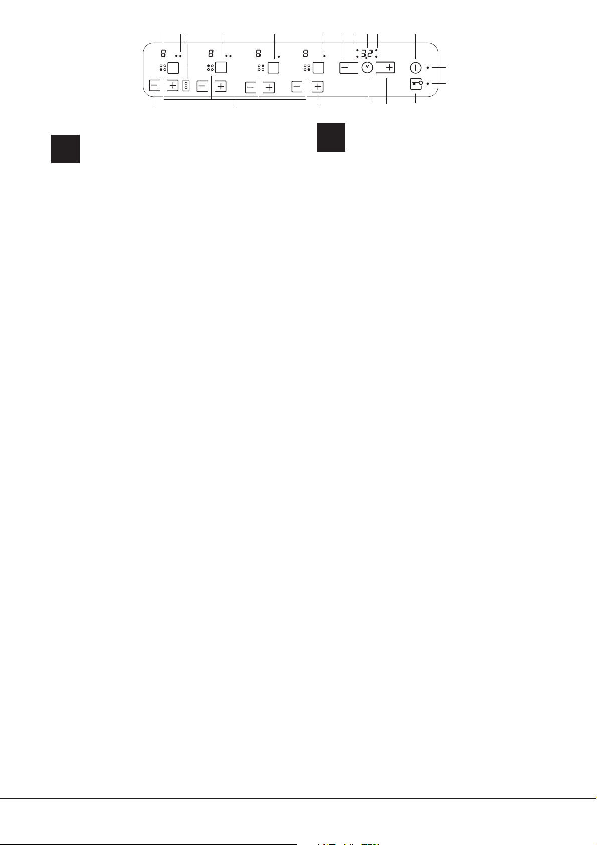
The control panel described in this manual is only a representative
example: it may not exactly match the panelon your appliance.
1 INCREASE TIME button increases the time value set on the
timer (see Start-up and use).
2 DECREASE TIME button decreases the time value set on
the timer (see Start-up and use).
3 INCREASE POWER button switches on the hotplate and
controls the power (see Start-up and use).
4 REDUCE POWER button controls the power and switches
off the hotplate (see Start-up and use).
5 COOKING ZONE SELECTED indicator shows a particular
cooking zone has been selected and therefore various
adjustments are possible.
6 POWER indicator provides a visual display for the current
heat level.
7 ON/OFF button switches the appliance on and off.
8 ON/OFF indicator light shows whether the appliance is on or
off.
9 PROGRAMME TIMER* button controls the cooking
programme times (see Start-up and use).
10 PROGRAMME TIMER* display shows which programme
has been selected (see Start-up and use).
11 COOKING ZONE PROGRAMMED* indicator lights show
which cooking zones are being used during a cooking
programme (see Start-up and use).
12 CONTROL PANEL LOCK button prevents accidental
changes to the hob settings (see Start-up and use).
13 CONTROL PANEL LOCK indicator light shows the control
panel has been locked (see Start-up and use).
14 BOOSTER button* activates the booster function - 3000 W -
of the cooking zone (see Start-up and use).
15 BOOSTER indicator light* shows that the booster function
has been activated.
16 TIMER* indicator light shows that the timer has been
activated
17 FLEXI ZONE button - activates the FLEXI ZONE mode
18 FLEXI ZONE indicator light shows FLEXI ZONE function
has been activated
19 MAX button- allows for an immediate activation of the
cookinfg zone on the maximum power level: 9
! This product complies with the requirements of the latest
European Directive on the limitation of power consumption of
the standby mode.
If no operations are carried out for a period of 2 minutes, after
the residual heat indicator lights turn off and the fan stops
(if present), the appliance automatically switches to the “off
mode”.
The appliance resumes the operating mode once the ON/OFF
button is pressed.
Le tableau de bord qui est
décrit n.a qu.une valeur d.exemple :
il peut ne pas correspondre au modèle acheté.
1 Touche AUGMENTATION DU TEMPS pour augmenter le temps
du programmateur (voir Mise en marche et utilisation).
2 Touche DIMINUTION DU TEMPS pour diminuer le temps du
programmateur (voir Mise en marche et utilisation).
3 Touche AUGMENTATION DE PUISSANCE pour allumer le foyer
et régler sa puissance (voir Mise en marche et utilisation).
4 Touche DIMINUTION DE PUISSANCE pour régler la puissance
et éteindre le foyer (voir Mise en marche et utilisation).
5 Voyant FOYER SELECTIONNÉ pour signaler que le foyer
correspondant a été sélectionné et que les régulations sont
donc possibles.
6 Indicateur de PUISSANCE : une colonne lumineuse pour
signaler le niveau de puissance atteint.
7 Touche ON/OFF pour allumer ou éteindre l’appareil.
8 Voyant ON/OFF : il signale si l’appareil est allumé ou éteint.
9 Touche PROGRAMMATEUR pour programmer la durée d’une
cuisson (voir Mise en marche et Utilisation).
10 Affi cheur PROGRAMMATEUR : pour affi cher les choix
correspondant à la programmation (voir Mise en marche et
utilisation).
11 Voyants FOYER PROGRAMMÉ : ils indiquent les foyers
quand une programmation est lancée (voir Mise en marche et
utilisation).
12 Touche VERROUILLAGE DES COMMANDES pour empêcher
toute intervention extérieure sur les réglages de la table de
cuisson (voir Mise en marche et Utilisation).
13 Voyant COMMANDES VERROUILLÉES : pour signaler
le verrouillage des commandes (voir Mise en marche et
Utilisation).
14 Touche BOOSTER pour brancher la suralimentation - 3000 W –
du foyer (voir Mise en marche et utilisation).
15 Voyant BOOSTER il signale que la fonction de suralimentation
du booster est activée.
16 Voyant MINUTEUR il signale que le minuteur est activé
17Touche FLEXI ZONE- pour utiliser la zone de cuisson FLEXI
ZONE
18 Voyant FLEXI ZONE il signale que la fonction du FLEXI
ZONE est activée.
19 Touche MAX - pour allumer le foyer à son niveau maximum 9.
! Ce produit est conforme à la nouvelle Directive Européenne sur
la réduction de la consommation d’énergie en mode standby.
Sans opérations pendant 2 minutes, après l’extinction des
voyants de chaleur résiduelle et l’arrêt du ventilateur (si existants),
l’appareil se place automatiquement en „off mode”.
Pour remettre l’appareil en mode de fonctionnement normal,
appuyer sur la touche ON/OFF.
* Only available in certain models.
* N’existe que sur certains modèles
Booster
Max
Max
Booster
13
1
2
3
5
4
6
7
8
9
10
11
12
14
15
17
18 16
19
Page 3

GB
3
Descripción del aparato
Panel de control
ES
Descrição do aparelho
Painel de comandos
PT
El panel de control se describe a continuación a modo de ejemplo: puede
no ser una exacta reproducción del
modelo adquirido.
1 Botón AUMENTO TIEMPO para aumentar el tiempo del
temporizador (ver Puesta en funcionamiento y modo de
empleo).
2 Botón DISMINUCIÓN TIEMPO para disminuir el tiempo
del temporizador (ver Puesta en funcionamiento y modo de
empleo).
3 Botón AUMENTO DE POTENCIA para encender la placa y
regular la potencia (ver Puesta en funcionamiento y uso).
4 Botón DISMINUCIÓN DE POTENCIA para regular la potencia
y apagar la placa (ver Puesta en funcionamiento y uso).
5 Piloto ZONA DE COCCIÓN SELECCIONADA indica que ha
sido seleccionada dicha zona de cocción y, por lo tanto, se
pueden realizar las distintas regulaciones
6 Indicador de POTENCIA: indica visualmente el nivel de calor
alcanzado.
7 Botón ON/OFF para encender y apagar el aparato.
8 Piloto ON/OFF: indica si el aparato está encendido o
apagado.
9 Botón TEMPORIZADOR DE PROGRAMACIÓN para
programar la duración de una cocción (ver Puesta en
funcionamiento y uso).
10 Display TEMPORIZADOR DE PROGRAMACIÓN: visualiza las
selecciones correspondientes a la programación (ver Puesta
en funcionamiento y uso).
11 Pilotos ZONA DE COCCIÓN PROGRAMADA: indican las
zonas de cocción cuando comienza una programación (ver
Puesta en funcionamiento y uso).
12 Botón BLOQUEO DE MANDOS para impedir modificaciones
fortuitas a las regulaciones de la encimera (ver Puesta en
funcionamiento y uso).
13 Piloto MANDOS BLOQUEADOS: indica que se ha producido
el bloqueo de los mandos (ver Puesta en funcionamiento y
uso).
14 Botón BOOSTER para encender la sobrealimentación -3000
vatios -de la zona de cocción (ver Puesta en funcionamiento y
uso ).
15 Piloto BOOSTER indica que está activada la función de
sobrealimentación booster.
16 Piloto CONTADOR DE MINUTOS indica que se ha activado
el contador de minutos
17 Botón FLEXI ZONE- para utilizar la zona de
cocción FLEXI ZONE
18 Piloto FLEXI ZONE indica que está activada la función FLEXI
ZONE.
19Botón MÁX. - enciende la zona de cocción de
nivel máximo 9
! Este producto satisface los requisitos establecidos por la
nueva Directiva europea sobre la limitación de los consumos
energéticos en standby.
Si no se realizan operaciones por 2 minutos, una vez que se
apagan los luces piloto del calor residual y del ventilador (si
están presentes), el aparato se coloca de forma automática en
el modo “off mode”.
El aparato vuelve al modo operativo utilizando la tecla ON/OFF.
O painel de comandos descrito a seguir está representado para
fins explicativos: pode não ser uma exacta
reprodução do modelo comprado.
1 Botão AUMENTAR TEMPO para aumentar o tempo do
timer (veja Início e utilização).
2 Botão DIMINUIR TEMPO para diminuir o tempo do timer
(veja Início e utilização).
3 Botão AUMENTO POTÊNCIA para ligar a chapa e regular
a potência (veja Início e utilização).
4 Botão DIMINUIÇÃO POTÊNCIA para regular a potência e
desligar a chapa (veja Início e utilização).
5 Indicador luminoso ZONA DE COZEDURA
SELECCIONADA indica que a zona de cozedura relativa
foi seleccionada e são portanto possíveis as várias
regulações.
6 Indicador POTÊNCIA sinaliza visualmente o nível de calor
alcançado.
7 Botão ON/OFF para ligar e desligar o aparelho.
8 Indicador ON/OFF: sinaliza se o aparelho está aceso ou
apagado.
9 Botão TIMER DE PROGRAMAÇÃO para regular a
programação da duração de uma cozedura (veja Início e
utilização).
10 Display TIMER DE PROGRAMAÇÃO: visualiza as
escolhas relativas à programação (veja Início e utilização).
11 Indicadores luminosos ZONA DE COZEDURA
PROGRAMADA: indicam as zonas de cozedura quando
se inicia uma programação (veja Início e utilização).
12 Botão BLOQUEIO DOS COMANDOS para impedir
modifi cações acidentais das regulações do plano de
cozedura (veja Início e utilização).
13 Indicador luminoso COMANDOS BLOQUEADOS: sinaliza
o bloqueio dos comandos (veja Início e utilização).
14 Botão BOOSTER para ligar a super alimentação - 3000 W
- da zona de cozedura (veja Início e Utilização).
15 Indicador luminoso BOOSTER indica que está activa a
função de super alimentação booster.
16 Indicador luminoso CONTADOR DE MUNITOS indica que
está activo o contador de minutos.
17 Botão FLEXI ZONE- para utilizar a zona de cozedura
FLEXI ZONE
18 Indicador luminoso FLEXI ZONE indica que está activa a
funçãoFLEXI ZONE.
19 Botão MAX - para ligar a zona de cozedura no nível
máximo 9
! Este produto satisfaz os requisitos impostos pela nova
Directiva Europeia sobre a limitação dos consumos
energéticos em stand-by.
Se não se efectuarem operações por 2 minutos, depois que
os indicadores de calor resíduo e da ventoinha (se presentes)
se desligarem, o aparelho coloca-se automaticamente na
modalidade “off mode”.
O aparelho voltará para a modalidade operativa ao carregar
na tecla ON/OFF.
* Presente sólo en algunos modelos.
* Há somente em alguns modelos.
Page 4

4
IT
DE
Beschreibung des Gerätes
Bedienfeld
Das hier beschriebene Bedienfeld dient nur als Beispiel, es handelt sich
nicht unbedingt um eine genaue
Widergabe des von Ihnen erworbenen Modells.
1 Taste ZEIT ERHÖHEN zur Verlängerung der Zeit des Timers
(siehe Inbetriebsetzung und Gebrauch).
2 Taste ZEIT HERABSETZEN zur Verkürzung der Zeit des Timers
(siehe Inbetriebsetzung und Gebrauch).
3 Taste ERHÖHEN DER LEISTUNG: Zum Einschalten sowie zur
Leistungsregelung der Kochzone (siehe Inbetriebsetzung und
Gebrauch).
4 Taste HERABSETZEN DER LEISTUNG: Zur Leistungsregelung
sowie zum Ausschalten der Kochzone (siehe Inbetriebsetzung und
Gebrauch).
5 Kontrollleuchte GEWÄHLTE KOCHZONE: Diese zeigt an, dass
die der Kontrollleuchte entsprechende Kochzone gewählt wurde
und die gewünschten Einstellungen demnach vorgenommen
werden können.
6 LEISTUNGSANZEIGE: Auf dieser ist der jeweils erreichte
Heizwert ersichtlich.
7 Taste ON/OFF: Zum Ein- bzw. Ausschalten des Gerätes.
8 Kontrollleuchte ON/OFF: Diese zeigt an, ob das Gerät ein- oder
ausgeschaltet ist.
9 Taste PROGRAMMIERUNGSTIMER: Mittels dieser Taste kann
die für jede Kochzone jeweils programmierte Zeit reguliert
werden (siehe Inbetriebsetzung und Gebrauch).
10 Display PROGRAMMIERUNGSTIMER: Auf diesem Display
werden die jeweils programmierten Zeiten angezeigt (siehe
Inbetriebsetzung und Gebrauch).
11 Kontrollleuchten PROGRAMMIERTE KOCHZONE: Diese
zeigen die Kochzonen an, die programmiert wurden (siehe
Inbetriebsetzung und Gebrauch).
12 Taste SPERRE DER SCHALTELEMENTE: Um versehentliche
Änderungen der am Kochfeld erfolgten Einstellungen zu
verhindern (siehe Inbetriebsetzung und Gebrauch).
13 Kontrollleuchte SCHALTELEMENTE GESPERRT: Diese
signalisiert, dass die Schaltelemente gesperrt wurden (siehe
Inbetriebsetzung und Gebrauch).
14 Taste BOOSTER: Mittels dieser kann die Kochzonenleistung auf
3000 W erweitert werden (siehe Inbetriebsetzung und Gebrauch).
15 Kontrollleuchte BOOSTER: zeigt an, dass die Booster-Funktion
eingeschaltet ist
16 Kontrollleuchte KURZZEITWECKER: Diese signalisiert, dass der
Kurzzeitwecker läuft.
17Taste FLEXI ZONE - um die Kochzone FLEXI
ZONE zu benutzen
•18Kontrollleuchte FLEXI ZONE: zeigt an, dass die FLEXI ZONEFunktion eingeschaltet ist
19Taste MAX- zum Einschalten der Kochzone auf
höchster Leistungsstufe 9
! Dieses Produkt entspricht den Vorschriften der neuen
Europäischen Richtlinie zur Einschränkung des Energieverbrauchs
im Standby.
Werden für 2 Minuten keine Tasten gedrückt, dann stellt sich das
Gerät nach Ausschalten der Anzeigen für Resthitze und des Lüfters
(wenn vorhanden) automatisch in den “off mode”.
Das Gerät kehrt durch Drücken der Taste ON/OFF in den
Betriebsmodus zurück.
Il pannello di controllo che qui viene descritto è
rappresentato a fini esemplificativi: può non essere una
esatta riproduzione del modello acquistato.
1/2Tasti AUMENTO/DIMINUZIONE TEMPO COTTURA -
regolare il tempo cottura (vedi Avvio e utilizzo).
3 Tasto AUMENTO POTENZA per accendere la piastra e
regolare la potenza (vedi Avvio e utilizzo).
4 Tasto DIMINUZIONE POTENZA per regolare la potenza e
spegnere la piastra (vedi Avvio e utilizzo).
5 Spia ZONA DI COTTURA SELEZIONATA indica che la
zona di cottura relativa è stata selezionata e quindi sono
possibili le varie regolazioni
6 Indicatore POTENZA: segnala visivamente il livello di
calore raggiunto.
7 Tasto ON/OFF per accendere e spegnere l’apparecchio.
8 Spia ON/OFF: segnala se l’apparecchio è acceso
o spento.
9 Tasto TIMER DI PROGRAMMAZIONE* per regolare la
programmazione della durata di una cottura (vedi Avvio e
utilizzo).
10 Display TIMER DI PROGRAMMAZIONE*: visualizza le
scelte relative alla programmazione (vedi Avvio e utilizzo).
11 Spie ZONA DI COTTURA PROGRAMMATA*: indicano le
zone di cottura quando si avvia una programmazione (vedi
Avvio e utilizzo).
12 Tasto BLOCCO DEI COMANDI per impedire modifi che
fortuite alle regolazioni del piano cottura (vedi Avvio e
utilizzo).
13 Spia COMANDI BLOCCATI: segnala l’avvenuto blocco dei
comandi (vedi Avvio e utilizzo).
14 Tasto BOOSTER* per accendere la sovralimentazione -
3000 W - della zona di cottura (vedi Avvio e utilizzo).
15 Spia BOOSTER* indica che è attiva la funzione di
sovralimentazione booster
16 Spia CONTAMINUTI* indica che è attivo il contaminuti
17 Tasto FLEXI ZONE- per utilizzare la zona di cottura FLEXI
ZONE
18 Indicatore FLEXI ZONE- indica che è attiva la funzione
FLEXI ZONE
19 Tasto MAX- per accendere la zona di cottura a livello
massimo 9
! Questo prodotto soddisfa i requisiti imposti dalla nuova
Direttiva Europea sulla limitazione dei consumi energetici in
standby.
Se non si eseguono operazioni per 2 minuti, dopo lo
spegnimento delle spie di calore residuo e della ventola
(ove presenti), l’apparecchio si dispone automaticamente in
modalità “off mode”.
L’apparecchio ritorna in modalità operativa agendo sul tasto
ON/OFF.
Descrizione dell’apparecchio
Pannello di controllo
* Presente solo in alcuni modelli.
* Nur bei einigen Modellen.
Page 5

GB
5
NL PL
Beschrijving van het apparaat
Bedieningspaneel
Opis urządzenia
Panel sterowania
Het bedieningspaneel dat hier wordt beschreven en afgebeeld
geldt alleen als voorbeeld: het is mogelijk dat het niet exact
overeenkomt met het door u aangeschafte model.
1 Toets TOENAME TIJD om de tijd van de timer toe te laten
nemen (zie Starten en gebruik).
2 Toets AFNAME TIJD om de tijd van de timer af te laten
nemen (zie Starten en gebruik).
3 Toets TOENAME VERMOGEN om de kookplaat aan te
zetten en het vermogen ervan te regelen (zie Starten en
gebruik).
4 Toets AFNAME VERMOGEN om het vermogen te regelen
en de kookplaat uit te zetten (zie Starten en gebruik).
5 Controlelampje GESELECTEERD KOOKGEDEELTE geeft
aan dat het betreffende kookgedeelte geselecteerd is en
dat u het kunt regelen.
6 AanwijzerVERMOGEN: geeft het bereikte warmteniveau
aan.
7 Toets ON/OFF voor het in- en uitschakelen van het
apparaat.
8 Controlelampje ON/OFF: geeft aan of het apparaat in- of
uitgeschakeld is.
9 Toets PROGRAMMERINGSTIMER om de programmering
van de kookduur te regelen (zie Starten en gebruik).
10 Display PROGRAMMERINGSTIMER: toont de keuzes
betreffende de programmering aan (zie Starten en gebruik).
11 Controlelampjes GEPROGRAMMEERD KOOKGEDEELTE:
tonen de kookgedeeltes aan als u een programmering start
(zie Starten en gebruik).
12 Toets BLOKKERING BEDIENINGSPANEEL om te
voorkomen dat er ongewilde wijzigingen aan de regeling
van het kookvlak worden uitgevoerd (zie Starten en gebruik).
13 Controlelampje BLOKKERING BEDIENINGSPANEEL:
toont dat de blokkering van het bedieningspaneel heeft
plaatsgevonden (zie Starten en gebruik).
14 BOOSTER toets om het extra vermogen - 3000 W - van de
kookzone in te schakelen (zie Starten en gebruik).
15 BOOSTER controlelampje, geeft aan dat het ‚booster’ extra
vermogen actief is.
16 Controlelampje TIMER geeft aan dat de timer actief is.
17 Toets FLEXI ZONE -om de kookzone FLEXI ZONE
18 Controlelampje FLEXI ZONE geeft aan dat de FLEXI ZONE
actief is.
19 Toets MAX- om de kookzone in te schakelen op het
maximale niveau 9
! Dit product voldoet aan de eisen die gesteld worden door
de nieuwe Europese Richtlijn voor energiebesparing voor
apparaten in de standby-stand.
Wanneer 2 minuten lang geen handelingen worden
uitgevoerd gaat het apparaat, na het uitgaan van de
waarschuwingslampjes voor restwarmte en voor de ventilator
(indien aanwezig), automatisch in de “off mode”.
Door op de ON/OFF toets te drukken, keert het apparaat weer
terug in de operationele stand.
Opisany tu panel sterowania jest przedstawiony jako przykład:
nie musi być dokładnie taki sam, jak panel zainstalowany w
zakupionym urządzeniu.
1 Przycisk ZWIEKSZENIA CZASU aby powiększyć czas timera
(patrz Uruchomienie i użytkowanie).
2 Przycisk ZMNIEJSZENIA CZASU aby skrócić czas timera (patrz
Uruchomienie i użytkowanie).
3 Przycisk ZWIEKSZENIA MOCY do wlaczania plyty i do regulacji
mocy (patrz Uruchomienie i uzytkowanie).
4 Przycisk ZMNIEJSZENIA MOCY do regulacji mocy i do
wylaczania plyty (patrz Uruchomienie i uzytkowanie).
5 Kontrolka WYBRANEGO POLA GRZEJNEGO wskazuje, ze
dane pole grzejne zostalo wybrane, a wiec mozliwe sa rózne
regulacje
6 Wskaźnik MOCY: wizualnie sygnalizuje osiągnięty poziom
ciepła.
7 Przycisk ON/OFF do wlaczania i wylaczania urzadzenia.
8 Kontrolka ON/OFF: sygnalizuje, czy urzadzenie jest wlaczone,
czy wylaczone.
9 Przycisk REGULATORA CZASOWEGO PROGRAMOWANIA
do regulacji programowania czasu trwania gotowania (patrz
Uruchomienie i uzytkowanie).
10 Wyswietlacz REGULATORA CZASOWEGO
PROGRAMOWANIA: wyswietla dane dotyczace programowania
(patrz Uruchomienie i uzytkowanie).
11 Kontrolki ZAPROGRAMOWANEGO POLA GRZEJNEGO:
wskazuja pola grzejne przy rozpoczynaniu programowania
(patrz Uruchomienie i uzytkowanie).
12 Przycisk BLOKADY STEROWANIA do zapobiegania
przypadkowym zmianom parametrów przy regulacji plyty
grzejnej (patrz Uruchomienie i uzytkowanie).
13 Kontrolka BLOKADY STEROWANIA : sygnalizuje zablokowanie
sterowania (patrz Uruchomienie i uzytkowanie).
14 Przycisk BOOSTER służy aby dojść do doładowania – 3000 W
– strefy gotowania (patrz Uruchomienie i użytkowanie).
15 Wskaźnik BOOSTER wskazuje, że włączona jest funkcja
doładwania booster.
16 Kontrolka MINUTNIKA wskazuje, ze minutnik jest wlaczony
17 Przycisk FLEXI ZONE- służy dowybrania funkcji pól grzejnych:
Flexi ZONE
18 Kontrolka FLEXI ZONE wskazuje, że włączona jest funkcja
Flexi ZONE.
19 Przycisk MAX-służy do włączenia pola grzejnego na
maksymalnym poziomie mocy: 9
! Ten produkt spełnia wymogi dyrektywy wspólnotowej dotyczącej
ograniczenia zużycia energii w trybie czuwania.
Jeśli przez 2 minuty nie są wykonywane żadne operacje, po
wyłączeniu wskaźnika ciepła resztkowego i wentylatora (jeśli
obecne), urządzenie automatycznie przechodzi w tryb „off mode”.
Urządzenie powraca do trybu aktywnego po naciśnięciu przycisku
ON/OFF.
* Slechts op enkele modellen aanwezig.
* Znajduje się tylko w niektórych modelach.
Page 6

RS
Панель управления, описание которои приводится ниже,
служит только в качестве примера: она может не в точности
соответствовать Вашеи модели
1 Кнопка УВЕЛИЧЕНИЕ ВРЕМЕНИ для
2 Кнопка УМЕНЬШЕНИЕ ВРЕМЕНИ для
3 Кнопка УВЕЛИЧЕНИЕ МОЩНОСТИ служит для
4 Кнопка УМЕНЬШЕНИЕ МОЩНОСТИ служит для
5 Индикатор ВЫБРАННАЯ ВАРОЧНАЯ ЗОНА
6 Индикатор МОЩНОСТЬ: показывает уровень
7 Кнопка ON/OFF (ВКЛ./ВЫКЛ.) служит для
8 Индикатор ON/OFF (ВКЛ./ВЫКЛ.): показывает
9 Кнопка ТАИМЕР ПРОГРАММИРОВАНИЯ служит
10 Дисплеи ТАИМЕРА ПРОГРАММИРОВАНИЯ:
11 Индикаторы ЗАПРОГРАММИРОВАННЫЕ
Описание изделия
Панель управления
увеличения времени таймера (см. Включение и
эксплуатация).
уменьшения времени таймера (см. Включение и
эксплуатация).
включения варочнои зоны и регуляции мощности
нагрева (см. Включение и эксплуатация).
регуляции мощности и выключения варочнои
зоны (см. Включение и эксплуатация).
показывает, что соответствующая варочная
зона была выбрана и следовательно возможно
произвести настроики ее функции.
нагрева.
включения и выключения изделия.
состояние изделия, включено или выключено.
для настроики продолжительности приготовления
(см. Включение и эксплуатация).
показывает различные настроики
программирования (см. Включение и
эксплуатация).
ВАРОЧНЫЕ ЗОНЫ: показывают варочные зоны
после запуска программирования ( см. Включение
и эксплуатация).
12 Кнопка БЛОКИРОВКА УПРАВЛЕНИИ служит
для защиты управлении варочнои панели
от случаиных измнении (см. Включение и
эксплуатация).
13 Индикатор УПРАВЛЕНИЯ ЗАБЛОКИРОВАНЫ
показывает, что управления заблокированы ( см.
Включение и эксплуатация).
14 Кнопка BOOSTER служит для включения
дополнительного электропитания – 3000 Вт
– индукционной конфорки (см. Включение и
эксплуатация).
15 Индикатор BOOSTER показывает, что функция
вольтодобавочного устройства включена.
16 Индикатор ТАИМЕР показывает, что таимер
включен
17 Кнопка FLEXI ZONE-Для использования варочной
зоны FLEXI ZONE
18 Индикатор FLEXI ZONE показывает, что FLEXI
ZONE включен
19 Кнопка MAX- для включения варочной зоны на
максимальном уровне мощности 9
! Данное изделие отвечает требованиям новой
Европейской Директивы по ограничению
энергопотребления в режиме энергосбережения.
Если в течение 2-х минут не производится
никаких действий после выключения
индикаторов остаточного тепла и вентилятора
(если они присутствуют), изделие автоматически
переходит в режим «ВЫКЛ.».
Возврат изделия в рабочий режим производится
кнопкой ВКЛ./ВЫКЛ.
* Имеется только в некоторых моделях.
6
Page 7

7
GB
Installation
! Before operating your new appliance please read
this instruction booklet carefully. It contains important
information concerning the safe operation, installation
and maintenance of the appliance.
! Please keep these operating instructions for future
reference. Pass them on to any new owners of the
appliance.
Positioning
! Keep all packaging material out of the reach of
children. It may present a choking or suffocation hazard
(see Precautions and tips).
! The appliance must be installed by a qualifi ed
professional in accordance with the instructions
provided. Incorrect installation may cause harm to
people and animals or may damage property.
Built-in appliance
Use a suitable cabinet to ensure that the appliance
functions properly.
• The supporting surface must be heat-resistant up to
a temperature of approximately 100°C.
• If the appliance is to be installed above an oven,
the oven must be equipped with a forced ventilation
cooling system.
• Avoid installing the hob above a dishwasher: if this
cannot be avoided, place a waterproof separation
device between the two appliances.
• Depending on the hob you want to install, the cabinet
must have the following dimensions (see fi gure):
560 +/- 1
490 +/- 1
48
590
520
690
520
560 +/- 1
490 +/- 1
48
Ventilation
To allow adequate ventilation and to avoid overheating of
the surrounding surfaces the hob should be positioned as
follows:
• At a minimum distance of 40 mm from the back
panel.
• So that a minimum distance of 20 mm is maintained
between the installation cavity and the cabinet
underneath.
• Kitchen cabinets adjacent to the appliance and taller
than the top of the hob must be at least 600 mm from
the edge of the hob.
FRONT SIDE
OF HOB
SUPPORTING
SURFACE
30
40
UNDERSIDE
OF HOB
5 mm
min. 20 mm
min. 20 mm
min. 40 mm
COMPARTMENT
5 mm
min. 40 mm
FAN-ASSISTED
OVEN
Page 8

8
GB
Fixing
The appliance must be installed on a perfectly level
supporting surface.
Any deformities caused by improper fi xing could affect
the features and operation of the hob.
The thickness of the supporting surface should be taken
into account when choosing the length of the screws for the
fi xing hooks:
• 30 mm thick: 23 mm screws
• 40 mm thick: 13 mm screws
Fix the hob as follows:
1. Use short fl at-bottomed screws to fi x the 4 alignment
springs in the holes provided at the central point of each
side of the hob.
2. Place the hob in the cavity, make sure it is in a central
position and push down on the whole perimeter until the
hob is stuck to the supporting surface.
3. For hobs with raised sides: After inserting the hob into its
cavity, insert the 4 fi xing hooks (each has its own pin) into
the lower edges of the hob, using the long pointed screws
to fi x them in place, until the glass is stuck to the supporting
surface.
! The screws for the alignment springs must remain
accessible.
! In order to adhere to safety standards, the appliance
must not come into contact with electrical parts once it
has been installed.
! All parts which ensure the safe operation of the
appliance must not be removable without the aid of a
tool.
Electrical connection
! The electrical connection for the hob and for any built-
in oven must be carried out separately, both for safety
purposes and to make extracting the oven easier.
Single-phase connection
The hob is equipped with a pre-connected electricity
supply cable, which is designed for single-phase
connection. Connect the wires in accordance with the
instructions given in the following table and diagrams:
Voltage and
mains frequency
Electrical cable Wire connection
220-240V 1+N ~
50 Hz
: yellow/green
N: the two blue wires together
L: brown and black together
Other types of connection
If the mains supply corresponds with one of the
following:
Voltage and mains frequency
• 400V - 2+N ~ 50 Hz
• 220-240V 3 ~ 50 Hz
• 400V 3 - N ~ 50 Hz
• 400V - 2+2N ~ 50 Hz
Separate the wires and connect them in accordance
with the instructions given in the following table and
diagrams:
Voltage and
mains frequency
Electrical cable Wire connection
400V - 2+N ~
50 Hz
220-240V 3 ~
50 Hz
400V 3-N ~
50 Hz
: yellow/green;
N: the two blue wires
together
L1: black
L2: brown
400V - 2+2N ~
50 Hz
: yellow/green;
N1: blue
N2: blue
L1: black
L2: brown
Connecting the electricity supply cable to the mains
If the appliance is being connected directly to the
electricity mains an omnipolar switch must be installed
with a minimum opening of 3 mm between contacts.
! The installer must ensure that the correct electrical
connection has been made and that it is fully compliant
with safety regulations.
Before connecting the appliance to the power supply, make
sure that:
• The appliance is earthed and the plug is compliant with
the law.
• The socket can withstand the maximum power of the
appliance, which is indicated on the data plate located on
the appliance itself.
• The voltage falls within the range of values indicated on
the data plate.
• The socket is compatible with the plug of the appliance.
If the socket is incompatible with the plug, ask an
authorised technician to replace it. Do not use extension
cords or multiple sockets.
! Once the appliance has been installed, the power
supply cable and the electrical socket must be easily
accessible.
! The cable must not be bent or compressed.
! The cable must be checked regularly and replaced by
authorised technicians only.
! The manufacturer declines any liability should these
safety measures not be observed.
! Do not remove or replace the power supply cable
for any reason. Its removal or replacement will void
the warranty and the CE marking. INDESIT does not
assume liability for accidents or damage arising from
replacement/removal of the original power supply cable.
Replacement can only be accepted when carried out by
personnel authorised by INDESIT and using an original
spare part.
Page 9

9
GB
Start-up and use
! The glue applied on the gaskets leaves traces of
grease on the glass. Before using the appliance, we
recommend you remove these with a special nonabrasive cleaning product. During the fi rst few hours of
use there may be a smell of rubber which will disappear
very quickly.
! A few seconds after the hob is connected to the electricity
supply, a buzzer will sound. The hob may now be switched
on.
Types of noise during normal hob operation:
• Buzz: due to the vibration of the metallic parts that
make up the induction element and the pot; it is
generated by the electromagnetic fi eld required for
heating and increases as the power of the induction
element increases.
• Soft whistle: heard when the pot placed on the
heating zone is empty; the noise disappears once
food or water is placed into the pot.
• Crackle: produced by the vibration of materials on
the bottom of the pot due to the fl ow of parasitic
currents caused by electromagnetic fi elds
(induction); can be more or less intense depending
on the material making up the bottom of the pot, and
decreases as the pot dimensions increase.
• Loud whistle: heard when two induction elements of
the same group function simultaneously at maximum
power and/or when the booster function is set on
the larger element while the other is auto-adjusted.
Noise is reduced by decreasing the power level of
the auto-adjusted induction element; pot bottom
layers made of different kinds of materials are among
the main causes of this noise.
• Fan noise: a fan is necessary to ensure the hob
functions correctly and to safeguard the electronic
unit from possible overheating. The fan functions at
maximum power when the large induction element is
at maximum power or when the booster function is on;
in all other cases, it works at average power depending
on the temperature detected. Furthermore, the fan may
continue to work even after switching the hob off, if the
temperature detected is high.
The types of noise listed above are due to induction
technology and are not necessarily operational faults.
! If the - or + button is pressed for an extended
period of time, the display scrolls quickly though the
power levels and timer minutes.
Switching on the hob
To switch the hob on, press and hold the
button for
approximately one second.
Switching on the cooking zones
Each cooking zone is controlled using a selector button
and a power adjustment device consisting of a double
- and + button.
• To begin operating a cooking zone, press the
corresponding control button and set the desired power
level (between 0 and 9) using the buttons - and +.
Booster function*
The booster function for some of the cooking zones may
be used to shorten heating-up times. It may be activated
by pressing the
Booster
button. The indicator light directly
above the button will illuminate. This function boosts the
power to 2000 W or 3000 W, depending on the size of the
relevant cooking zone.
The booster stops automatically after 4 minutes. While
the booster for one of the cooking zones is active, the
corresponding front or rear cooking zone will operate
at a reduced power level (e.g. if the booster for the rear
left-hand hotplate has been activated, the power level of
the front left-hand hotplate will be reduced). For further
information, please refer to the Technical description of
the models.
Switching off the cooking zones
To switch off a cooking zone, select it using the corresponding
selector button and:
• Press the - button: the power of the cooking zone will
progressively decrease until it is switched off.
Programming the cooking duration
! All the cooking zones may be programmed
simultaneously, for a duration between 1 and 99 minutes.
1. Select the cooking zone using the corresponding
selector button.
2. Adjust the power level of the cooking zone.
3. Press the
programming button. The indicator light
corresponding to the selected zone will start fl ashing.
Page 10

10
GB
4. Set the cooking duration using the - and +
buttons.
5. Confi rm by pressing the
button or automatic
selection occurs after 10 seconds.
The timer begins counting down immediately.
A buzzer sounds for approximately 1 minute and the
cooking zone switches off when the set programme has
fi nished.
Repeat the above procedure for each hotplate you wish
to programme.
Using multiple programmes and the display
If one or more hotplates are programmed, the display
will show the data for the hotplate with the least time
remaining, and the light corresponding to the position of
the hotplate will fl ash. The lights corresponding to the
other hotplates programmed will be switched on.
To visualise the time remaining for the other
programmed hotplates, press the button
repeatedly: the time remaining for each hotplate will be
shown sequentially in a clockwise order,
starting from the front left hotplate.
Changing the programme
1. Press the button repeatedly until the duration
you wish to change is shown.
2. Use the buttons to set the new duration.
3. Confi rm by pressing the button.
To cancel a programme, follow the above instructions.
At step 2, press the - button: the duration decreases
progressively until it reaches 0 and switches off. The
programme resets and the display exits programming
mode.
Timer
The hob must be switched on.
The timer can be used to set a duration up to 99
minutes.
1. Press the programming button until the timer
indicator light is illuminated
.
2. Set the desired duration using the - and + buttons.
3. Confi rm by pressing the button.
The timer begins counting down immediately. When the
time has elapsed, a buzzer will sound (for one minute).
Control panel lock
When the hob is switched on, it is possible to lock the
oven controls in order to avoid accidental changes
being made to the settings (by children, during cleaning,
etc.). Press the
button to lock the control panel:
the indicator light above the button will switch on.
To use any of the controls (e.g. to stop cooking), you
must switch off this function. Press the button for a
few moments, the indicator light will switch off and the
lock function will be removed.
Switching off the hob
Press the button
to switch off the appliance - do not
rely solely on the pan sensor.
If the control panel lock has been activated, the controls
will continue to be locked even after the hob is switched
on again. In order to switch the hob on again, you must
fi rst remove the lock function.
“Demo” mode
It is possible to set the hob to a demonstration mode
where all the controls work normally but the heating
elements do not switch on. To activate the “demo” mode
the hob must be switched on, with all the hotplates
switched off.
• Press and hold the + and - buttons simultaneously
for 6 seconds. When the 6 seconds have elapsed,
the ON/OFF and CONTROLS LOCKED indicator
lights will fl ash for one second. Release the + and
- buttons and press the button;
• The display will show the text DE and MO and the
hob will be switched off.
• When the hob is switched on again it will be set to
the “demo” mode.
To exit this mode, follow the procedure described
above. The display will show the text DE and OF and
the hob will be switched off. When it is next switched
on, the hob will function normally.
Practical advice on using the appliance
! Use cookware made from materials which are
compatible with the induction principle (ferromagnetic
material). We especially recommend pans made from:
cast iron, coated steel or special stainless steel adapted
for induction. Use a magnet to test the compatibility of
Page 11

11
GB
The FlexiZONE mode
The FLEXI Zone can be used to set the power of two
„interconnected” hotplates to the same level. It can be
activated if the two hotplates are OFF, by pressing the
FLEXI ZONE button
The FLEXI ZONE can be activated while the hob is on
by pressing the FLEXI ZONE button once; the LEDs
corresponding to both linked hotplates light up.
The 2 LEDs remain lit as long as the hotplates are
linked (if FLEXI ZONE button is pressed again, the
hotplates are disconnected and are both set to power
level 0).
Pressing the +, - or Max buttons for one of the two Flexi
hotplates also affects the display corresponding to the
other hotplate.
To deactivate the FLEXI ZONE, press the button .
A timer may be set for the FLEXI zone; this appears on
the display and both LEDs corresponding to the linked
hotplates light up. When the Timer button is pressed,
the two linked hotplates are treated as if they were a
single zone.
Selecting and using FLEXI ZONE
To begin using the FLEXI ZONE, press the button.
To set the power level (see above).
FLEXI ZONE operation
Once you have selected FLEXI ZONE by pressing
the button , the 2 LEDs corresponding to the FLEXI
ZONE for both hotplates light up; it will then be possible
to control both as if they were a single zone. The power
level will appear on both displays. If only the upper or
lower part is in use, the display corresponding to the
unused zone will begin to fl ash, and after 3 minutes
cooking will automatically revert to standard mode (not
FLEXI).
! Once activated, the FLEXI ZONE can also be
programmed, using the same procedure as described
for the individual hotplates.
! Accessories
For optimal FLEXI ZONE performance, we recommend
the use of pans with an elliptical or elongated base and
a major diameter of at least 250 mm; if using pans with
a smaller diameter, we recommend positioning them in
the upper or lower part as indicated by the X symbol.
If the saucepan is not in the centre of the screen
printing detail, you may hear a whistling sound or
a slight buzzing noise; this does not indicate a hob
malfunction. We recommend adjusting the position of
the pan so that it is in the centre of the FLEXI ZONE.
Practical cooking advice
ª
Pressure cooking
Pressure cooker
Frying
Grilling Boiling
Very high-flame
cooking
High-flame
cooking
Medium-flame cookingLow-flame
cooking
Very
low-flame
cooking
•
•
¶
Crêpes Cooking on a high flame and browning
(roasts, steaks, escalopes, fish fillets,
fried eggs)
¶
§
Fast thickening (liquid juices)
Boiling water (pasta, rice, vegetables)
Milk
§
S
Slow thickening (dense juices)
S
¢
Bain-marie cooking Pressure cooking after whistle
¢
£
™
Low-flame cooking (stews)
Reheating dishes
™
¡
Chocolate sauce Keeping food hot
Page 12

12
GB
the cookware.
*
SUITABLE
UNSUITABLE
Cast iron
Enamelled steel
Special stainless steel
Copper,
Aluminium, Glass, Earthenware,
Ceramic, non magnetic Stainless steel
In addition, to obtain the best results from your hob:
• Use pans with a thick, fl at base in order to fully utilise
the cooking zone.
• Always use pans with a diameter which is large
enough to cover the hotplate fully, in order to use all
the available heat.
• Make sure that the base of the cookware is always
clean and dry, in order to fully utilise and extend the
life of both the cooking zones and the cookware.
• Avoid using the same cookware which has been
used on gas burners: the heat concentration on gas
burners may distort the base of the pan, causing it
not to adhere correctly.
Safety devices
Pan sensor
Each cooking zone is equipped with a pan sensor
device. The hotplate only emits heat when a pan with
suitable measurements for the cooking zone is placed
on it. If the indicator light is fl ashing, it may indicate:
• An incompatible pan
• A pan whose diameter is too small
• The pan has been removed from the hotplate.
Overheating protection
If the electronic elements overheat, the hob switches off
automatically and F appears on the display, followed
by a fl ashing number. When the temperature has
reached a suitable level, this message disappears and
the hob may be used again.
Safety switch
The appliance has a safety switch which automatically
switches the cooking zones off after they have been in
operation for a certain amount of time at a particular
power level. When the safety switch has been triggered,
the display shows “0”.
For example: the right rear hotplate is set to 5 and will
switch off after 5 hours of continuous operation, while
the front left hotplate is set to 2 and will switch off after
8 hours.
Buzzer
This can also indicate several irregularities:
• An object (a pan, cutlery, etc.) has been placed on
the control panel for more than 10 seconds.
• Something has been spilt on the control panel.
• A button has been pressed for too long. All of the
above situations may cause the buzzer to sound.
Remove the cause of the malfunction to stop the
buzzer. If the cause of the problem is not removed,
the buzzer will keep sounding and the hob will switch
off.
Power level
1
2
3
4
5
6
7
8
9
Maximum operating time in hours
9
8
7
6
5
4
3
2
1
Page 13

13
GB
Precautions and tips
! This appliance has been designed and manufactured
in compliance with international safety standards. The
following warnings are provided for safety reasons and
must be read carefully.
This appliance conforms to the following
European Economic Community directives:
- 2006/95/EEC dated 12/12/06 (Low Voltage) and
subsequent amendments;
- 2004/108/EEC dated 15/12/04 (Electromagnetic
Compatibility) and subsequent amendments;
- 93/68/EEC dated 22/07/93 and subsequent amendments.
- 1275/2008 stand-by/off mode.
General safety
! Make sure that the air inlet behind the fan grille is
never obstructed. The built-in hob should, in fact, be
provided with suitable ventilation for the cooling of the
electronic components used in the appliance.
! We advise against the installation of an induction hob
above an under-the-counter refrigerator (heat) or above
a washing machine (vibration s). In fact, there would
be insuffi cient space for the ventilation of electronic
components.
• The appliance was designed for domestic use inside the
home and is not intended for commercial or industrial
use.
• The appliance must not be installed outdoors, even in
covered areas. It is extremely dangerous to leave the
appliance exposed to rain and storms.
• Do not touch the appliance when barefoot or with wet or
damp hands and feet.
• The appliance must be used by adults only for the
preparation of food, in accordance with the instructions
provided in this booklet. Do not use the hob as a worktop
or chopping board.
• The glass ceramic hob is resistant to mechanical shocks,
but it may crack (or even break) if hit with a sharp object
such as a tool. If this happens, disconnect the appliance
from the electricity mains immediately and contact a
Service Centre.
• Ensure that power supply cables of other electrical
appliances do not come into contact with the hot parts of
the hob.
• Remember that the cooking zones remain relatively hot
for at least thirty minutes after they have been switched
off. An indicator light provides a warning when residual
heat is present (see Start-up and use).
• Keep any object which could melt away from the
hob, for example plastic and aluminium objects, or
products with a high sugar content. Be especially
careful when using plastic fi lm and aluminium foil or
packaging: if placed on surfaces which are still hot,
they may cause serious damage to the hob.
• Always make sure that pan handles are turned
towards the centre of the hob in order to avoid
accidental burns.
• When unplugging the appliance, always pull the plug
from the mains socket; do not pull on the cable.
• Never perform any cleaning or maintenance work
without having disconnected the appliance from the
electricity mains.
• The appliance should not be operated by people
(including children) with reduced physical, sensory
or mental capacities, by inexperienced individuals or
by anyone who is not familiar with the product. These
individuals should, at the very least, be supervised
by someone who assumes responsibility for their
safety or receive preliminary instructions relating to
the operation of the appliance.
• For the attention of wearers of pacemakers or
other active implants:
The hob complies with all current standards on
electromagnetic interference.
Your induction hob is therefore perfectly in keeping
with legal requirements (89/336/CEE directives). It
is designed not to create interference on any other
electrical apparatus being used on condition that
the apparatus in question also complies with this
legislation.
Your induction hob generates short-range magnetic
fi elds.
To avoid any interference between your induction
hob and a pacemaker, the latter must be designed to
comply with relevant regulations.
In this respect, we can only guarantee our own
product conformity. Please consult the pacemaker
manufacturer or your doctor concerning its
conformity or any possible incompatibility.
• Do not let children play with the appliance.
• Do not place metal objects (knives, spoons, pan lids,
etc.) on the hob as they may become hot.
• The appliance is not intended to be operated by
means of an external timer or separate remote-
control system.
Disposal
• When disposing of packaging material: observe local
legislation so that the packaging may be reused.
• The European Directive 2002/96/EC relating to Waste
Electrical and Electronic Equipment (WEEE) states
that household appliances should not be disposed of
using the normal solid urban waste cycle. Exhausted
appliances should be collected separately in order to
optimise the cost of re-using and recycling the materials
inside the machine, while preventing potential damage
to the atmosphere and to public health. The crossed-out
dustbin is marked on all products to remind the owner of
their obligations regarding separated waste collection.
For further information relating to the correct disposal of
exhausted household appliances, owners may contact
the public service provided or their local dealer.
Page 14

14
GB
Care and maintenance
Switching the appliance off
Disconnect your appliance from the electricity supply
before carrying out any work on it.
Cleaning the appliance
! Do not use abrasive or corrosive detergents (for
example, products in spray cans for cleaning barbecues
and ovens), stain removers, anti-rust products, powder
detergents or sponges with abrasive surfaces: these
may scratch the surface beyond repair.
! Never use steam cleaners or pressure cleaners on the
appliance.
• It is usually suffi cient simply to wash the hob using a
damp sponge and dry it with absorbent kitchen towel.
• If the hob is particularly dirty, rub it with a special
glass ceramic cleaning product, then rinse well and
dry thoroughly.
• To remove more stubborn dirt, use a suitable scraper.
Remove spills as soon as possible, without waiting
for the appliance to cool, to avoid residues forming
crusty deposits. You can achieve excellent results
by using a rust-proof steel wire sponge - specifi cally
designed for glass ceramic surfaces - soaked in
soapy water.
• If any plastic or sugary substances are accidentally
melted on the hob, remove them immediately with
the scraper, while the surface is still hot.
• Once it is clean, the hob may be treated with a
special protective maintenance product: the invisible
fi lm left by this product protects the surface from
drips during cooking. This maintenance task should
be carried out while the appliance is warm (not hot)
or cold.
• Always remember to rinse the appliance well with
clean water and dry it thoroughly: residues can
become encrusted during subsequent cooking
processes.
Stainless steel frame (only in models with outer frame)
Stainless steel can be marked by hard water which has
been left on the surface for a long time, or by cleaning
products containing phosphorus.
After cleaning, it is advisable to rinse the surface well
and dry it thoroughly. If water is spilt on the surface, dry
it quickly and thoroughly.
! Some hobs have an aluminium frame which is
similar to stainless steel. Do not use any cleaning or
degreasing products which are not suitable for use with
aluminium.
Disassembling the hob
If it is necessary to disassemble the hob:
1. Loosen the screws fi xing the alignment springs on
each side.
2. Loosen the screws holding the fi xing hooks in each
corner.
3. Take the hob out of its installation cavity.
! Do not attempt to repair the appliance yourself. If the
appliance breaks down, contact a Service Centre.
Technical description of the models
The induction system is the quickest existing way
of cooking. Unlike traditional hotplates where the
cooking zone heats up, with the induction system
heat is generated directly inside pans which have
ferromagnetic bases.
Key:
I = single induction cooking zone
B = booster: the power level of the cooking zone may
be boosted to 3000 W
* = the maximum power level is limited while the
booster is activated for the relevant rear cooking
zone (see Start-up and use).
Hobs
KIO 632 CC
Cooking zone
Power (W)
Back Left
I 1400
Back Right
I 2200 – B 3000* - 1600 if Front Right*
Front Left
I 1400
Front Right
I 1400 – B 2000* – 600 if Back Right*
Total power
6400
 Loading...