

Part Number:
3420210
Fitting Kit No:
6173022 (suits all year models)
Available Lower Panel Supplementary kits:
3520010 06-09 FJ Cruiser
3520020 2010 ON FJ Cruiser
3520030 Field fix kit is required for Australian
delivery vehicles in addition to the main bar kit.
Product Description:
Vehicle/s:
ARB WINCH BULL BAR
TOYOTA FJ CRUISER 2006 ON
WARNING
REGARDING VEHICLES EQUIPPED WITH SRS AIRBAG:
When installed in accordance with these instructions, the front protection bar does not affect operation of
the SRS airbag.
ALSO, NOTE THE FOLLOWING:
♦ This product must be installed exactly as per these instructions using only the hardware supplied.
♦ In the event of damage to any bull bar component, contact your nearest authorised ARB stockist.
Repairs or modifications to the impact absorption system must not be attempted.
♦ Do not use this product for any vehicle make or model, other than those specified by ARB.
♦ Do not remove labels from this bull bar.
♦ This product or its fixing must not be modified in any way.
♦ The installation of this product may require the use of specialized tools and/or techniques
♦ It is recommended that this product is only installed by trained personnel
♦ These instructions are correct as at the publication date. ARB Corporation Ltd. cannot be held
responsible for the impact of any changes subsequently made by the vehicle manufacturer
♦ During installation, it is the duty of the installer to check correct operation/clearances of all
components
♦ Work safely at all times
♦ Unless otherwise instructed, tighten fasteners to specified torque
ARB 4x4 ACCESSORIES
Corporate Head Office
42-44 Garden St Tel: +61 (3) 9761 6622
Kilsyth, Victoria Fax: +61 (3) 9761 6807
AUSTRALIA 3137
Australian enquiries sales@arb.com.au
North & South American enquiries sales@arbusa.com
Other international enquiries exports@arb.com.au
www.arb.com.au
Last Rev Date: 18/07/11 Page 1 of 15 Fitting instructions# 3787968
Copyright © 2005 by ARB Corporation Limited. All rights rese rved, t his document must not be reproduced without the express au thority of ARB Corporation Ltd
FITTING REQUIREMENTS
REQUIRED TOOLS FOR FITMENT OF PRODUCT:
Basic Tool Kit External Circlip pliers
17mm Tube Spanner Power Drill 13mm capacity
7mm, 10mm and 13mm drill bits Cold chisel
HAVE AVAILABLE THESE SAFETY ITEMS WHEN FITTING PRODUCT:
Protective eyewear
Hearing protection
NOTE: ‘WARNING’ notes in the fitting procedure relate to OHS situations, where to avoid a
potentially hazardous situation it is suggested that protective safety gear be worn or a safe work
procedure be employed. If these notes and warnings are not heeded, injury may result.
FASTENER TORQUE SETTINGS:
SIZE Torque Nm Torque lbft
M6 9Nm 7lbft
M8 22Nm 16lbft
M10 44Nm 32lbft
M12 77Nm 57lbft
OPTIONAL LIGHT SETS TO SUIT THIS PRODUCT:
♦ ARB 6821201 Fog Light Kit Suit 3163015
♦ Up to IPF 900 SERIES FOG OR DRIVING LIGHT SETS
Last Rev Date: 18/07/11 Page 2 of 15 Fitting instructions# 3787968
Copyright © 2005 by ARB Corporation Limited. All rights rese rved, t his document must not be reproduced without the express au thority of ARB Corporation Ltd
Fitting Kit 6172343 PARTS LISTING
APPLICATION. PART NO. QTY DESCRIPTION
Mount Assembly To Chassis
Bull Bar To Impact Absorber
Indicators To Bull Bar
Winch To Bull Bar
Number Plate To Bull Bar
Miscellaneous
Supplementary Kit:
3520010 06-09 Models:
Stone Tray
Supplementary Kit:
3520020 2010 ON Models:
Stone Tray and Wing Under Panels
3756848
3756851R
3756851L
3193741
6151306
6151255
6151189
6151094
4581049
4581050
5846401
6151357
4581040
6151026
3163015
6821152
6821151L
6821151R
EG50
3756499
6151021
4581044
6151132
BLB560
4581040
6151074
6821189
6151384
6781408
6821132
180302
3162152
3756857
6542088
6151300
6151213
4584310
4581287
6542111
6522795 R&L
6151300
6151213
4584310
4581082
4581287
6151132
6151234
4581307
4581047
3787825
1
1
1
2
2
8
6
2
18
10
4
10
10
10
1
2
1
1
1
1
2
2
2
2
4
2
2
2
1
2
8
2
1
1
4
4
4
4
1
1 pr
14
16
6
10
16
2
2
4
2
1
Bracket Mount Assembly
Bracket Mount Brace RHS
Bracket Mount Brace LHS
Captive Nut Plate
Nut Cage M12 x 1.75
Bolt M12 x 1.75 x 40mm
Nut M12 x 1.75
Bolt M12 x 1.25 x 30mm
Washer Flat M12
Washer Spring M12
Spacer 8mm
SEMS Bolt M10 x 1.5 x 30mm
Washer Flat M10 x 2mm
Nut M10 x 1.5
Combination Light Surround Kit
Turn signal / clearance light loom
Turn Signal / Clearance Light
Turn Signal / Clearance Light
Rubber Grommet
Bracket Control Box
Bolt M8 x 20mm
Washer Flat M8
Nut Flange M8
Cable Black 560mm
Washer Flat 3/8” x 1”
Bolt 1 ¾” x 3/8” UNC
Grommet Nylon Nut
Screw Pan Hd Phil 5x16mm
Tape Double sided
Rubber Grommet 3/8” ID
Cable Ties
Plastic Plug 16mm DIA
Bracket Bracing Lower Grille
Stone Tray 06-09
Nut Cage 6mm
Bolt M6 x 20mm BZ
Washer Flat M6 BZ
Washer Spring M6 BZ
Stone Tray 2010 ON
Wing under panels
Nut Cage 6mm
Bolt M6 x 20mm BZ
Washer Flat M6 THK BZ
Washer Flat M6 BZ
Washer Spring M6 BZ
Nut Flange 8mm
Bolt M8 x 25mm BZ
Washer Flat Panel M8 BZ
Washer Spring M8 BZ
Template drilling mount holes
Last Rev Date: 18/07/11 Page 3 of 15 Fitting instructions# 3787968
Copyright © 2005 by ARB Corporation Limited. All rights rese rved, t his document must not be reproduced without the express au thority of ARB Corporation Ltd
FITTING PROCEDURE
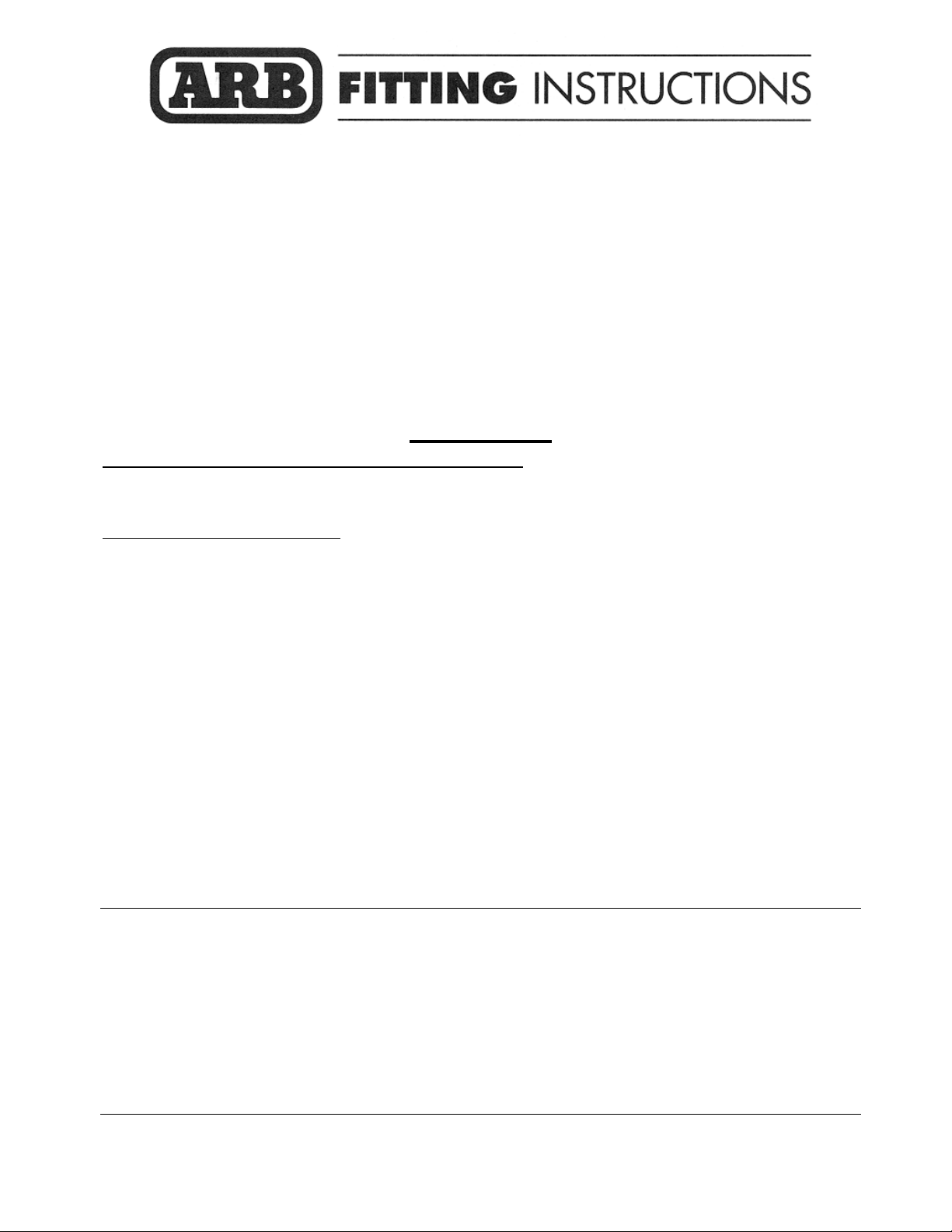
1. Remove protective plate if fitted
2. Remove front fasteners only from stone tray.
Retain fasteners for reuse.
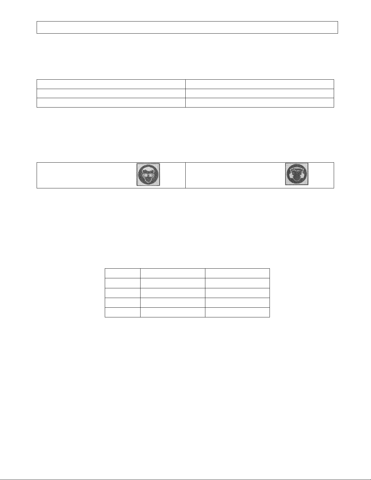
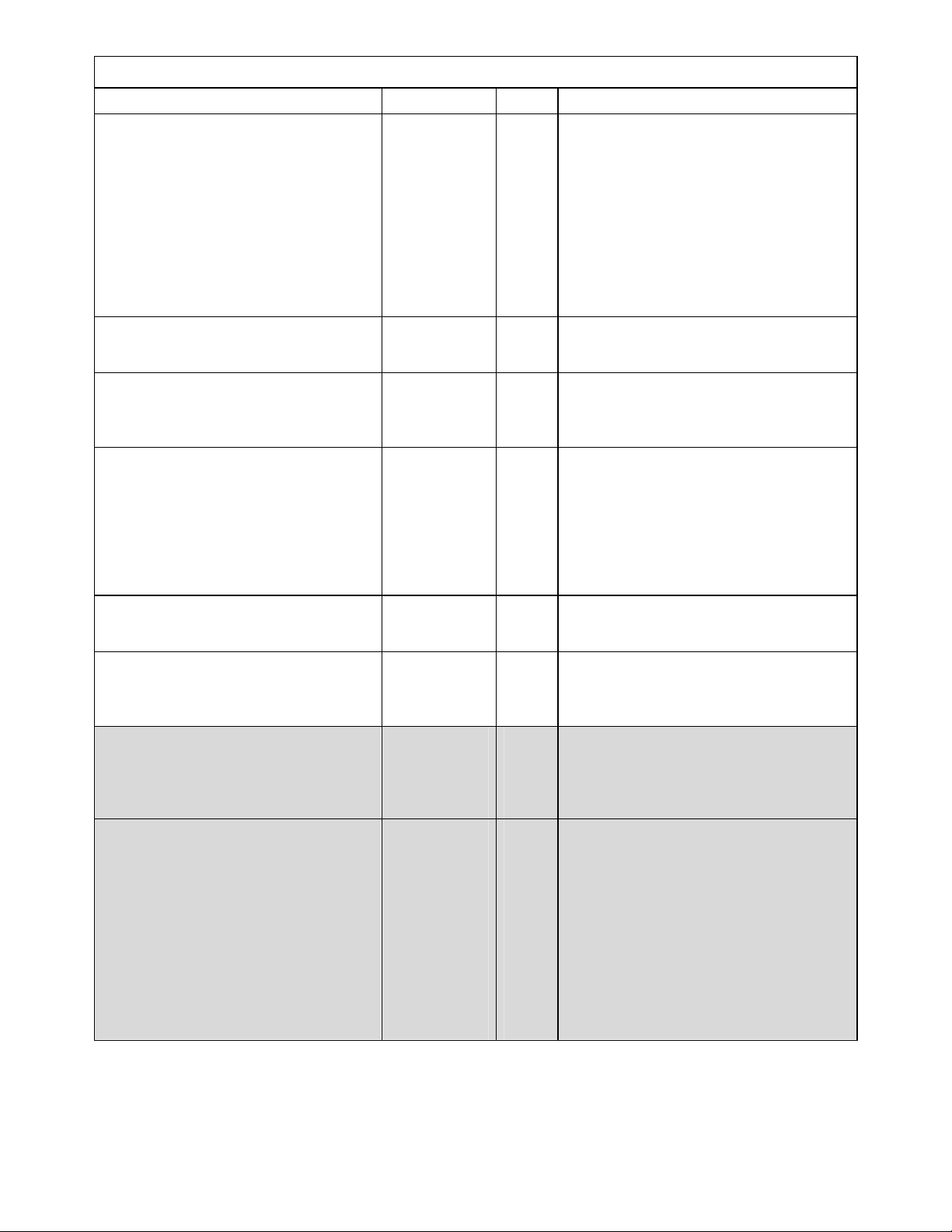
3. Remove lower bumper fixing screws and
screws in wheel arch area
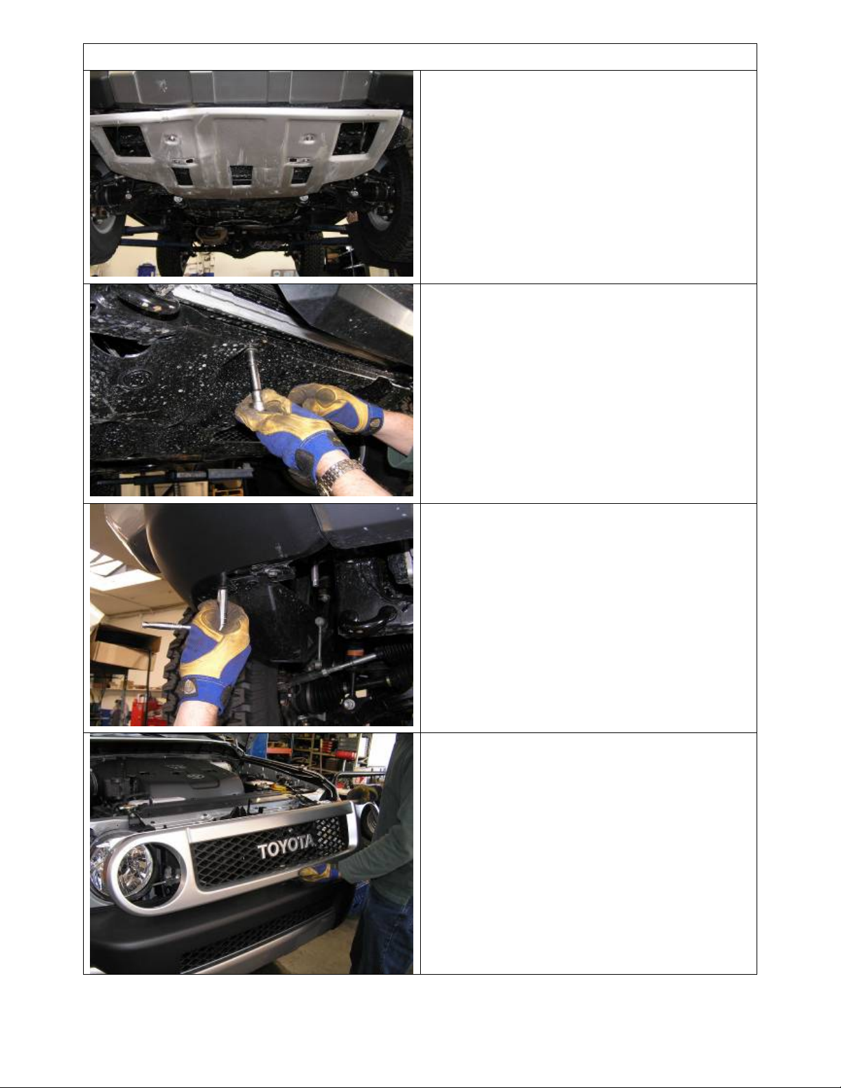
4. Remove grille. Screws are located in tabs at
top of grille. Once these are removed
carefully release clips some are located along
the inside lower section.
Last Rev Date: 18/07/11 Page 4 of 15 Fitting instructions# 3787968
Copyright © 2005 by ARB Corporation Limited. All rights rese rved, t his document must not be reproduced without the express au thority of ARB Corporation Ltd
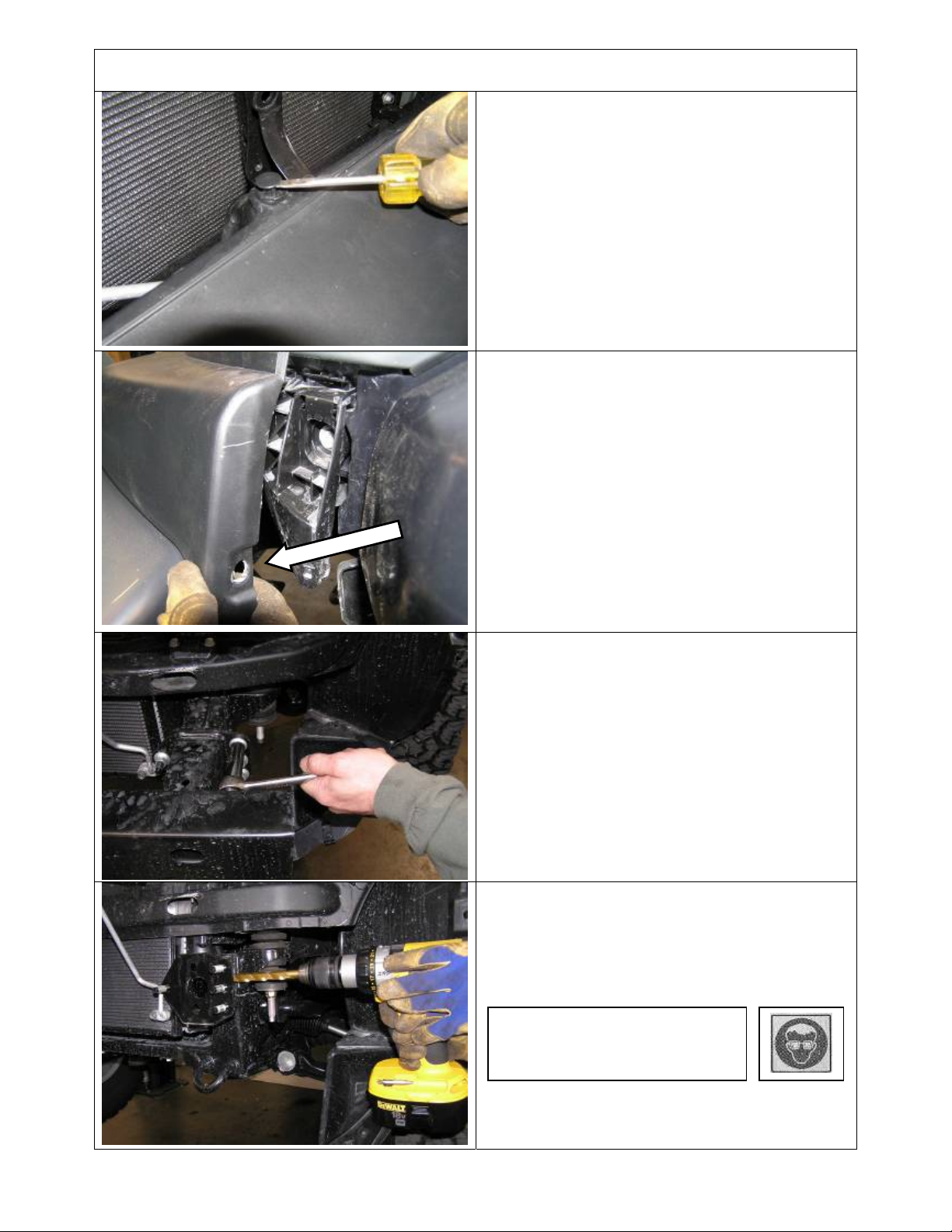
FITTING PROCEDURE
5. Remove plastic rivets along top of bumper
6. Remove screw then remove front bumper
cover from vehicle.
NOTE: Prise the rear lip of the bumper off the
retaining spigot where screw was located (as
shown with arrow) then pull bar wing outward
.
7. Remove front bumper reinforcing bar.
NOTE: Retain the 8 x flange nuts removed for
fitment of the bull bar chassis mount.
8. Using the 13mm drill bit and power drill, drill
out the M8 captive nut located at the outboard
side of the chassis as shown, on both sides of
the vehicle.
Warning: Drilling operations can
result in flying metal debris,
safety glasses should be worn.
Last Rev Date: 18/07/11 Page 5 of 15 Fitting instructions# 3787968
Copyright © 2005 by ARB Corporation Limited. All rights rese rved, t his document must not be reproduced without the express au thority of ARB Corporation Ltd

FITTING PROCEDURE
9. Check that the nut body is completely
removed, if it is not cleared, using a cold
chisel and hammer chisel the remainder off.
Warning: Hammering and
chiselling operations can result in
flying metal debris, safety glasses
should be worn.
10. Fit an M12 cage nut to each of the captive
nut plates 3193741.
Use a M12
flat washer
as a spacer
between
chassis and
bracket.
11. Fit the chassis mount braces to the vehicle
using the M12 x 30mm fine pitched bolt, M12
spring and flat washers supplied in the lower
hole. Use an M12 flat washer as a spacer
between the brace and the chassis at the
upper hole and fix with an M12 x 40mm bolt
M12 spring and flat washers and M12 x 1.75
nut. Do not tighten the bolts.
12. Insert the captive nut assembly through the
front of the chassis and line it up with the hole
at the end of the mount brace. Fix in place
with the M12 x 1.75 x 40mm bolt, M12 flat
and spring washers. Break off the end of the
captive nut plate. Do not tighten yet.
Last Rev Date: 18/07/11 Page 6 of 15 Fitting instructions# 3787968
Copyright © 2005 by ARB Corporation Limited. All rights rese rved, t his document must not be reproduced without the express au thority of ARB Corporation Ltd

FITTING PROCEDURE
Position brace so
spacer won’t protrude
from the chassis
13. Hold the 8mm spacer against the chassis
mount brace forward facing surface and
position the brace so that the spacers sit just
below the surface of the chassis front face.
Tighten the bolts.
14. If fitting the bar to an Australian delivered
vehicle, please refer now to fitting instructions
#3787967 to relocate the power steering
lines. If not proceed to the next step.
15. Fit the chassis mount bracket to the chassis
using the original flange nuts removed with
the bumper reinforcing bar. Centre the
chassis mount bracket and tighten.
CAUTION: When fitting the Chassis mounting
bracket carefully bend the air-conditioning pipe
out of the way.
16. If required, carefully bend A/C piping clear of
mount bracket assembly as shown, with a
minimum clearance of 20mm (3/4”).
CAUTION: Piping must not rub on
sharp edges, secure with cable tie
and protective sheath if required.
17. Fix the chassis mount bracket to the chassis
mount brace using M12 x 40mm bolts, M12
spring and flat washers, the 8mm spacers
and M12 x 1.75 nuts. Tighten bolts
Last Rev Date: 18/07/11 Page 7 of 15 Fitting instructions# 3787968
Copyright © 2005 by ARB Corporation Limited. All rights rese rved, t his document must not be reproduced without the express au thority of ARB Corporation Ltd

V
FITTING PROCEDURE
NOTE: If fitting winch continue
through step 17, if not skip to step 29
18. For ease of access the winch gearbox
handle needs to be rotated. To do this undo
all the cap screws, carefully lift the gearbox
clear of the winch body so as not to damage
the gasket. (Do not lift the gearbox more
than a couple of millimetres) Rotate the
gearbox anti-clockwise two hole spaces (72°).
Re-fit the cap screws.
iew on gearbox end
19. Using a 12mm (1/2”) drill bit, drill two new
holes in the roller fairlead 25mm below the
original holes.
Original hole.
New hole 25mm lower.
Warning: Drilling operations can result in
flying metal debris, safety glasses should be
20. Remove the three screws from the control
box and remove the cover.
21. Replace the two cables marked “A” and “F1”
and replace them with the two cables
(BLB560) supplied with the fitting kit. Label
the cables the same as the original to assist
in the wiring of the winch.
22. Place the winch on a table with the feet
facing up and using an assistant; carefully lift
the bull bar on top of the winch.
23. Attach the winch to the bull bar using two 1
½” x 3/8” bolts from the winch fitting kit, 3/8”
spring washer and 3/8” flat washers in the top
holes.
24. Fit the 4 x M6 cage nuts from inside of the
lower flange on the pan, where the stone tray
will bolt up.
NOTE: Access to this area for cage nut fitment
will be restricted once the RFL is fitted so it is
important to insert these now.
Last Rev Date: 18/07/11 Page 8 of 15 Fitting instructions# 3787968
Copyright © 2005 by ARB Corporation Limited. All rights rese rved, t his document must not be reproduced without the express au thority of ARB Corporation Ltd

FITTING PROCEDURE
25. Position the roller fairlead, and remove the
circlips from the lower of the vertical rollers
and push the pins up to give access to the
lower bolts.
26. Fix the roller fairlead to the bar using the 1
¾” x 3/8” bolts, spring and flat washers
27. Fit the control box bracket to the bull bar
using two M8 x 20mm bolts, M8 flat washers
and M8 flange nuts.
28. Fit the control box to the control box bracket
and connect the power cables to the winch as
per the winch instructions.
29. Connect the ground wire to the tension bar of
the winch.
CAUTION: Cable-tie all cables together and
keep all cables clear of sharp edges and all
moving parts.
30. Insert square grommets into holes in front of
bar for licence plate fixing. Place the doublesided tape along the top edge of the number
plate. Using supplied black Hi-lo screws,
attach the licence plate to the bull bar.
NOTE: If winch is not fitted, licence plate can
be located lower on bar front to cover RFL
opening.
Last Rev Date: 18/07/11 Page 9 of 15 Fitting instructions# 3787968
Copyright © 2005 by ARB Corporation Limited. All rights rese rved, t his document must not be reproduced without the express au thority of ARB Corporation Ltd

FITTING PROCEDURE
31. Remove original grille brace member. Retain
screws.
32. Fit supplied replacement brace and secure
with original fasteners
33. With the help of an assistant position the bull
bar on the chassis bracket and fix with six
M10 x 30mm bolts, M10 spring and flat
washers.
CAUTION: Nip up bolts, but do not tighten
them yet.
34. Position the bull bar so that there is an even
gap of approximately 5mm from the top face
of the bar to the underside of the body edge.
Then tighten all the bolts.
Last Rev Date: 18/07/11 Page 10 of 15 Fitting instructions# 3787968
Copyright © 2005 by ARB Corporation Limited. All rights rese rved, t his document must not be reproduced without the express au thority of ARB Corporation Ltd

FITTING PROCEDURE
35. With the bull bar in position drill Dia10mm
pinning holes, one though pilot hole in mount
bracket and one through hole in upright for
both sides of mounts.
Warning: Drilling operations can
result in flying metal debris,
safety glasses should be worn.
36. Fix in place using two M10 x 30mm SEMS
bolts, M10 Flat washers and M10 x 1.5 nuts
per side.
37. Assemble and install combination light
surrounds (P# 3163015) as per instructions
# 3786421 supplied with surround kit. Note:
Optional fog lamps can be installed at this
point as per fitting instruction #. 3783315
supplied with fog lamp kit # 6821201.
38. Wire the combination lamp to the vehicles
indicator and clearance lamps.
Caution: Cable tie all cables together and keep
all cables clear of sharp edges and moving
parts.
39. Wire up lights using loom extensions
supplied in fitting kit.
Wiring loom detail for flasher and clearance
lamps supplied standard with bullbar;
Red Clearance lamp
Green Flasher lamp
Black Ground
Wiring loom detail on FJ Cruiser;
LHS
Blue Flasher
Green Run
Wh/Blk Ground
RHS
Pink Flasher
Green Run
Wh/Blk Ground
NOTE: Other wiring detail supplied with
accessories.
Last Rev Date: 18/07/11 Page 11 of 15 Fitting instructions# 3787968
Copyright © 2005 by ARB Corporation Limited. All rights rese rved, t his document must not be reproduced without the express au thority of ARB Corporation Ltd

FITTING PROCEDURE
FROM SUPLEMENTARY KITS – 3520010 & 20
STONE TRAY
40. Fit the bull bar stone tray by sliding the tray
under the front of the vehicles original stone
tray
41. Fit the front of the stone tray to the bull bar
with four M6 x 20mm bolts, M6 large panel
washers and M6 spring washers.
ONLY FROM SUPLEMENTARY KIT - 3520020
WING UNDER PANELS
Check first, then if there are no holes in lower
flange of wing for fixing panels- follow the next
6 steps
42. Cut out the hole position paper template
Final shape of template
43. Locate on the RH wing lower flange and
align to the inner flange edge then tape in
position
44. Centre punch the hole positions onto the
wing lower flange
45. Remove template, apply to LH wing and
centre punch holes
46. Drill the holes to Dia 9mm (11/32”)
47. Deburr then touch up the bared steel with
rust preventing paint
Warning: Drilling operations can
result in flying metal debris,
safety glasses should be worn.
Last Rev Date: 18/07/11 Page 12 of 15 Fitting instructions# 3787968
Copyright © 2005 by ARB Corporation Limited. All rights rese rved, t his document must not be reproduced without the express au thority of ARB Corporation Ltd

FITTING PROCEDURE
FROM SUPPLEMENTARY KIT 3520020
48. Fit the cage nuts to the inside faces of the
wing under panels as shown
49. Fit the wing under panels as shown using M6
bolts and washer sets to bolt to wing
underside
If there is
brace lower flange to fix inside flange of the
sing under panels....
50. Use M8 x 25mm bolts, washer sets and
a corresponding hole in the chassis
flange nut to bolt to chassis brace lower
flange
If there is no corresponding hole in chassis
brace lower flange to fix inside flange of the
wing under panels....
51. On the RH side, lift the inner locating flange
up to the chassis reinforcing bracket lower
flange, position centrally then mark and drill a
Dia 7mm (11/32”) hole through the existing
reinforcing bracket flange. Repeat for LH side
52. Touch up holes with rust preventing paint
53. Use M8 x 25mm bolts, washer sets and
flange nut to bolt to chassis brace lower
flange
Warning: Drilling operations can
result in flying metal debris, safety
glasses should be worn.
If wing panels are fitted...
54. Drill 2 x Dia 7mm (5/16”) holes in each fender
liner lining up with the cage nuts in the rear
flanges of the wing under panels so the liners
can be fastened to the rear flange
55. Fix in place using 2 x M6 x 20 Bolts and
washer sets per side
Warning: Drilling operations can
result in flying metal debris, safety
glasses should be worn.
Last Rev Date: 18/07/11 Page 13 of 15 Fitting instructions# 3787968
Copyright © 2005 by ARB Corporation Limited. All rights rese rved, t his document must not be reproduced without the express au thority of ARB Corporation Ltd

FITTING PROCEDURE
56. Trim fender liner to coincide with the
underside of the wing under panel lower face
as shown
If no wing panels are fitted...
57. Trim fender liner horizontally with sharp knife
approximately 30mm (1 ¼”) below hole as
shown.
58. Trim corner as shown.
59. Drill 7mm securing holes in the liner and the
plastic bracket arm as shown.
Warning: Drilling operations can
result in flying metal debris,
safety glasses should be worn.
Last Rev Date: 18/07/11 Page 14 of 15 Fitting instructions# 3787968
Copyright © 2005 by ARB Corporation Limited. All rights rese rved, t his document must not be reproduced without the express au thority of ARB Corporation Ltd

FITTING PROCEDURE
60. Feed a cable tie through holes and secure.
61. The painted color coded area of vehicle
visible in the region around the trimmed
fender liner may be spray painted black to
hide this area.
NOTES: When finished make sure all bolts are tightened and that all wiring
is clear of hot, sharp and moving parts.
Also supplied in the kit are two 3/8” rubber grommets and two 16mm plugs.
The rubber grommets are for the two holes in the top pan if lights are being
fitted. The two plastic plugs are for the holes in the top surface of the wings
if no CB aerials are going to be connected.
CAUTION: If winch fitted, check that the air conditioner piping is clear of the
winch by at least 20mm (3/4”). Fit a sheath around tubing and secure with
cable tie to prevent chaffing which may lead to piping damage.
FITTED PRODUCT ON VEHICLE
Last Rev Date: 18/07/11 Page 15 of 15 Fitting instructions# 3787968
Copyright © 2005 by ARB Corporation Limited. All rights rese rved, t his document must not be reproduced without the express au thority of ARB Corporation Ltd
 Loading...