

Page 1

Part Number:
Product
3915030 F/KIT 6172445
ARB SAHARA BAR
Description:
Suited to
TOYOTA TUNDRA YEAR MODELS 07 ON
vehicle/s:
WARNING
REGARDING VEHICLES EQUIPPED WITH SRS AIRBAG:
When installed in accordance with these instructions, the front protection bar does not affect operation of
the SRS airbag.
ALSO, NOTE THE FOLLOWING:
♦
This product must be installed exactly as per these instructions using only the hardware supplied.
♦
In the event of damage to any bull bar component, contact your nearest authorised ARB stockist.
Repairs or modifications to the impact absorption system must not be attempted.
♦
Do not use this product for any vehicle make or model, other than those specified by ARB.
♦
Do not remove labels from this bull bar.
♦
This product or its fixing must not be modified in any way.
♦
The installation of this product may require the use of specialized tools and/or techniques
♦ It is recommended that this product is only installed by trained personnel
♦
These instructions are correct as at the publication date. ARB Corporation Ltd. cannot be held
responsible for the impact of any changes subsequently made by the vehicle manufacturer
♦
During installation, it is the duty of the installer to check correct operation/clearances of all
components
♦
Work safely at all times
♦
Unless otherwise instructed, tighten fasteners to specified torque
ARB 4x4 ACCESSORIES
Corporate Head Office
42-44 Garden St Tel: +61 (3) 9761 6622
Kilsyth, Victoria Fax: +61 (3) 9761 6807
AUSTRALIA 3137
Australian enquiries [email protected]
North & South American enquiries [email protected]
Other international enquiries [email protected]
www.arb.com.au
Last Rev Date: 29/10/2008 Page 1 of 24 Fitting instructions# 3783321
Copyright © 2005 by ARB Corporation Limited. All rights reserved, this document must not be reproduced without the express authority of ARB Corporation Ltd
Page 2
GENERAL CARE AND MAINTENANCE
By choosing an ARB Bar, you have bought a product that is one of the most sought after 4WD products in
the world. Your bar is a properly engineered, reliable, quality accessory that represents excellent value.
To keep your bar in original condition it is important to care and maintain it following these
recommendations:
Prior to exposure to the weather your bar should be treated to a Canuba based polish on all exposed
surfaces. It is recommended that this is performed on a six monthly basis or following exposure to
salt, mud, sand or other contaminants.
As part of any Pre Trip Preparation, or on an annual basis, it is recommended that a thorough visual
inspection of the bar is carried out, making sure that all bolts and other components are torqued to the
correct specification. Also check that all wiring sheaths, connectors, and fittings are free of damage.
Replace any components as necessary. This service can be performed by your local authorised ARB
Stockist.
To maintain the polished alloy frame, wash and chamois dry regularly using car wash specific products
Polish the alloy surfaces with Briteshine® or similar products
Small scratches can be removed by using Autosol® metal polish or similar
FITTING REQUIREMENTS
REQUIRED TOOLS FOR FITMENT OF PRODUCT:
Metric socket and spanner sets 8-25mm range
Screwdrivers, Philips and Flat blade Dia 22.0 (7/8”) holesaw
Power Drill 13mm (1/2”) capacity Dia 7.0mm (5/16”) and 10.0mm (25/64”) drill bits
Allen (Hex) Key Set
Hacksaw Scriber Centre punch
Files, round, square and flat Hammer 300mm Rule
External Circlip pliers
HAVE AVAILABLE THESE SAFETY ITEMS WHEN FITTING PRODUCT
:
Protective eyewear
NOTE: ‘WARNING’ notes in the fitting procedure relate to OHS situations, where to avoid a
potentially hazardous situation it is suggested that protective safety gear be worn or a safe work
procedure be employed. If these notes and warnings are not heeded, injury may result.
Hearing protection
FASTENER TORQUE SETTINGS:
SIZE Torque Nm Torque lbft
M6 9Nm 7lbft
M8 22Nm 16lbft
M10 44Nm 32lbft
M12 77Nm 57lbft
Last Rev Date: 29/10/2008 Page 2 of 24 Fitting instructions# 3783321
Copyright © 2005 by ARB Corporation Limited. All rights reserved, this document must not be reproduced without the express authority of ARB Corporation Ltd
Page 3

OPTIONAL LIGHT SETS TO SUIT THIS PRODUCT:
♦
FOG LAMP SET P# 6821201, ADD FOR NON FACTORY FOG VEHICLES ONLY P#MD02 LOOM
KIT, P#180209 SWITCH AND P#180215 SWITCH CAP FOR FOGS
♦
UP TO IPF 900 SERIES FOG OR DRIVING LIGHT SETS
♦
IPF 840 FYS FOG LIGHTS CAN BE FITTED TO LOWER PAN AREA
AVAILABLE BUFFER/FRAME SETS:
♦
BUFFER SET ONLY, BLANK BUFFERS P#5100150 OR
♦ FRAME, P#5115030 FRAME ASSEMBLY PLUS P#5100140 BUFFER SET WITH HOLES
PARTS LISTING
APPLICATION. PART NO. QTY DESCRIPTION
Mount Brackets To Chassis
Brace Assembly
Bull Bar To Mount Bracket Assy
Stone Tray to Bull Bar
Light Surround To Bull Bar
Winch To Bull Bar
Winch Hole Cover Fitment
(If Not Fitting Winch)
Buffer fasteners
Number Plate To Bull Bar
Miscellaneous
3757559R
3757559L
6151428
6151429
6151396
5846400
4681264
6151357
6151321
6151357
6151321
6151255
6151189
4581049
4581050
6522677
6151303
6151234
4581063
4581047
3163015
6821151R
6821151L
6821152
180701
180302
6821192
3756499
6151234
4581045
4581047
6151132
180302
EG50
6151074
6151128
6151256
6191013
6522695
4581304
6151128 12 Nut M6 Flanged
6821189
6151384
6781408
3162152 2 Plug Blanking Dia 16
1
1
2
2
2
2
1
7
7
2
2
6
6
12
6
1
6
6
6
6
1
1
1
2
6
4
2
1
2
2
2
2
10
2
2
2
2
1
1
4
2
2
1
Bracket Mount RHS
Bracket Mount LHS
Flange Nut M12
Chassis Stud M12 x 265 x 1.75
Nut Clevis
Packer M12 x 8mm
Brace
SEMS Bolt M10 x 1.5 x 30mm
Nut Flanged M10 x 1.5
SEMS Bolt M10 x 1.5 x 30mm
Nut Flanged M10 x 1.5
Bolt M12 x 1.75 x 40mm
Nut M12 x 1.75
Washer Flat M12
Washer Spring M12
Stone Tray
Nut Cage 8mm
Bolt M8 x 25mm BZ
Washer Flat M8 x25.4 x 3
Washer Spring M8
Light Surround
Indicator Assembly RH
Indicator Assembly LH
Loom
Scotch Locks
Cable Tie
Bulb 12V 10W BA15S
Bracket Control Box Univ.
Bolt M8 x 25 BZ
Washer Flat M8 BZ
Washer Spring M8 BZ
Nut M8 Flanged
Cable Tie
Grommet Dia 50mm
Bolt 3/8 x 1 3/4
Nut Flange M6
Screw M6 St/Stl Button Head
Extrusion Winch Cover
Panel Winch Cover
Washer M6 st stl
Grommet round
Screw self tapping pan head
Tape double sided
Last Rev Date: 29/10/2008 Page 3 of 24 Fitting instructions# 3783321
Copyright © 2005 by ARB Corporation Limited. All rights reserved, this document must not be reproduced without the express authority of ARB Corporation Ltd
Page 4

Opt: Blank Buffers Only Kit
P#5100150
Opt: Buffers Suit Frame
P# 5100140
Opt: Frame Assy
Kit P#5115030
NOTE:
♦
WHEN FITTING FRAME ASSEMBLY ONLY, LABEL FOR FRAME TILT OPERATION FOR HOOD
CLEARANCE MUST BE APPLIED TO TOP FACE OF SAHARA BUMPER IN THE POSITION IDENTIFIED
IN THESE FITTING INSTRUCTIONS. FAILURE TO APPLY THIS PERMANENT LABEL AT SAHARA
BUMPER FITMENT INDEMNIFIES ARB CORPORATION OF ANY LIABILITY ARISING FROM THE
OPERATION OR USE OF THIS PRODUCT.
♦
KIT CONTAINS M6 FLANGE NUTS TO SUIT FITMENT OF BUFFERS. WHEN FITTING FRAME
ASSEMBLY WITH BUFFERS, REQUIRED FITTING KIT COMPONENTS COME WITH FRAME.
♦
FACTORY FOGS CANNOT BE REUSED WITH THIS BAR, INSTEAD FIT ARB FOG LAMP KIT 6821201
(SEE NOTE P3).
PARTS LISTING CONT.
3163016R
3163016L
3163017R
3163017L
3757574R
3757574L
3757571
3757692
4581308
4581309
6151046
4581072
4581045
4581040
4581288
6151042
4581047
4581048
6151068
6151234
6151232
6151364
6151417
6151127
6151162
6151212
6151122
6151132
6151321
4558427
5670001
5670002
5670003
5670004
5670005
6564507
2125214
1 1 Buffer Large Sahara
Buffer Large Sahara
1 1 Buffer Large with hole Sahara
Buffer Large with hole Sahara
Bracket Hinge
1
Bracket Hinge
1
Bracket Wedge Pad Support
2
Bracket Slam Latch Operation
1
Washer Nylon 16.0 ID x 30 OD x 3
2
Washer Nylon 8.0 ID
1
Washer Flat M6
2
Washer Flat M6 Large
4
Washer Flat M8 BZ
6
Washer Flat M10
4
Washer Flat M10 Large
2
Washer Spring M6
2
Washer Spring M8 BZ
5
Washer Spring M10
6
Bolt ¼ UNC x 1”
2
Bolt M8 x 25 BZ
5
Bolt M10 x 30
2
Screw Cap M10 x 30 ZP
4
Screw M4 x 16 CSK HD ZP
4
Nut M4 Nyloc
4
Nut M6 Nyloc
4
Nut M8 Nyloc
1
Nut 5/16UNC
1
Nut M8 Flanged
4
Nut M10 Flanged
2
Link Arm Slam Latch
1
Striker
1
Latch Slam
1
Connector Clip 4mm Wire
2
Wedge Pad Urethane
2
Spring Lever Return
1
Bush Pivot Bracket
2
Sticker Frame Tilt Operation
1
Last Rev Date: 29/10/2008 Page 4 of 24 Fitting instructions# 3783321
Copyright © 2005 by ARB Corporation Limited. All rights reserved, this document must not be reproduced without the express authority of ARB Corporation Ltd
Page 5
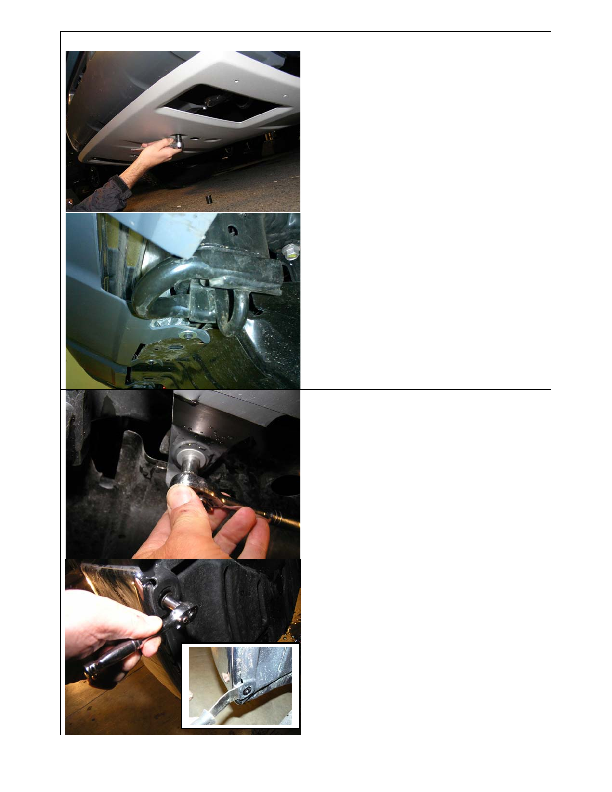
REMOVAL OF BUMPER
1. If fitted, remove factory bash plate
2. Remove tow hooks and bolts, set aside to be
refitted.
3. Remove lower bumper retaining screws.
4. Remove all lower fender liner retaining
screws to bumper.
Last Rev Date: 29/10/2008 Page 5 of 24 Fitting instructions# 3783321
Copyright © 2005 by ARB Corporation Limited. All rights reserved, this document must not be reproduced without the express authority of ARB Corporation Ltd
Page 6
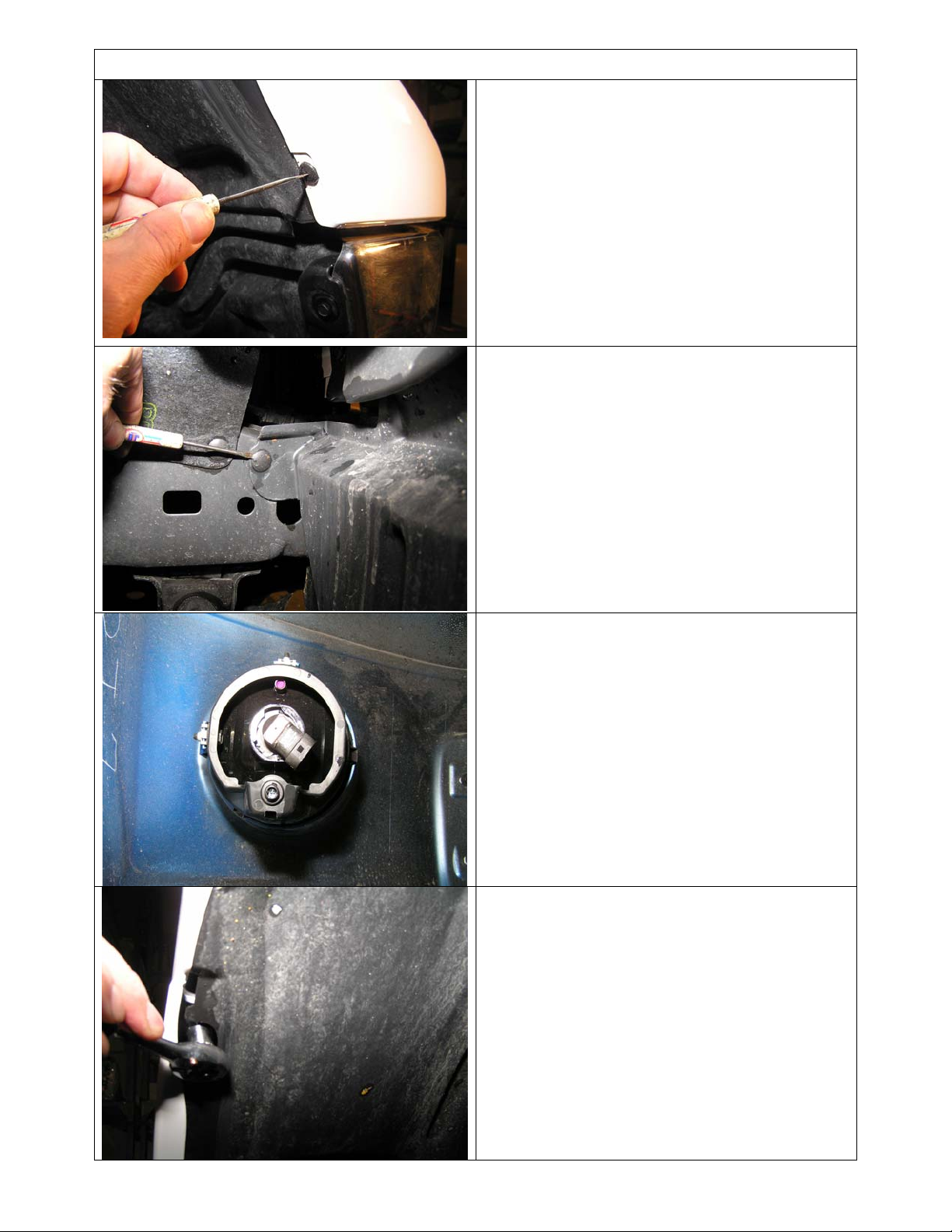
REMOVAL OF BUMPER
5. Remove upper fender liner retaining scrivets.
6. Prise out lower fender liner plastic push in
plugs. Remove lower fender liner completely,
they will not be reused.
7. If OE fog lights and/or parking sensors fitted
in bumper, undo electrical connections.
8. Remove bumper wing retaining screws in
upper wheel arch area.
Last Rev Date: 29/10/2008 Page 6 of 24 Fitting instructions# 3783321
Copyright © 2005 by ARB Corporation Limited. All rights reserved, this document must not be reproduced without the express authority of ARB Corporation Ltd
Page 7
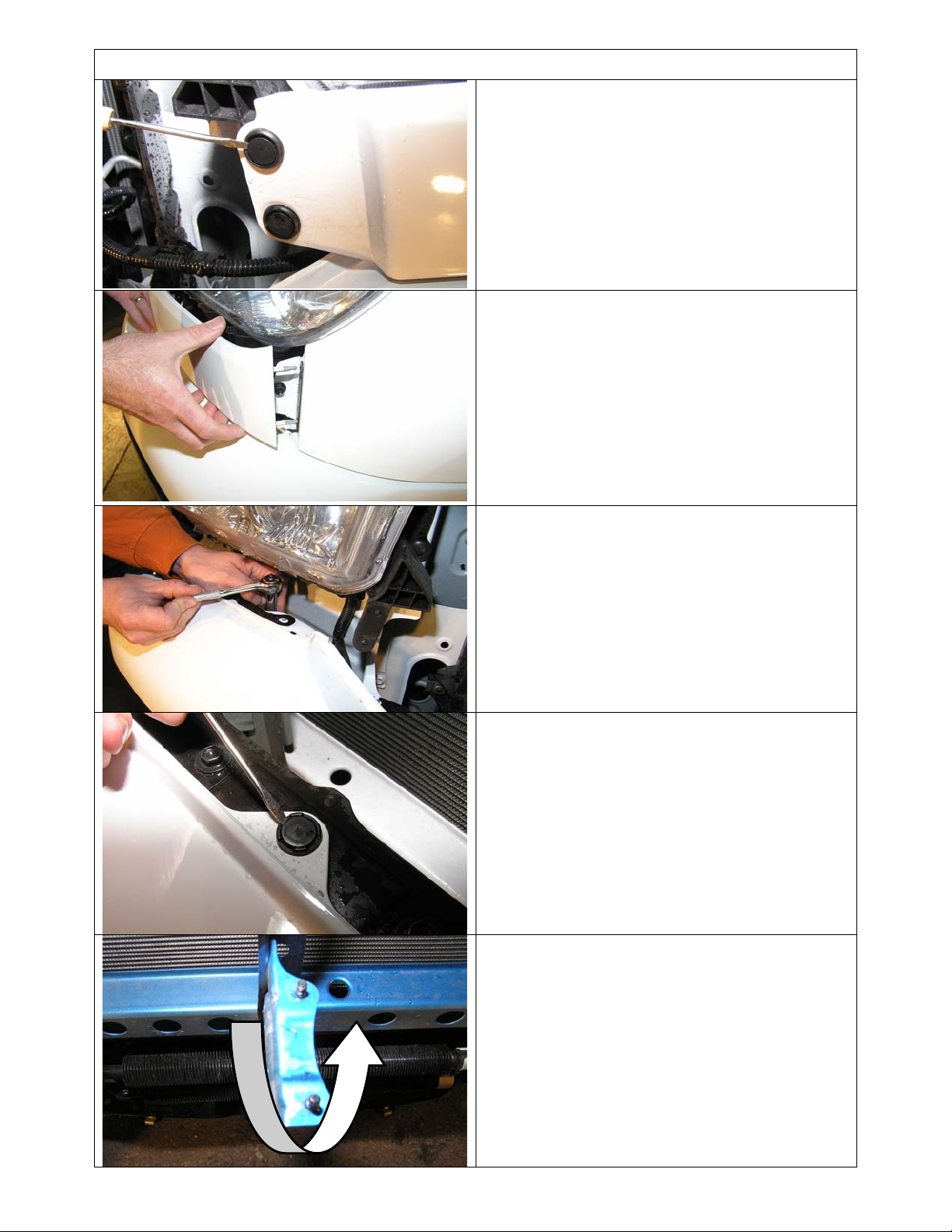
REMOVAL OF BUMPER
9. Remove push in plugs from trim piece under
headlamp.
10. Carefully prise the trim pieces free by pulling
them forward and twisting to release plugs
out of retaining sockets.
11. Remove screws retaining bumper located
under headlamp area.
12. Remove plugs securing upper bumper tabs.
13. If winch is to be fitted to bull bar, bend the
forward facing section of vertical brace
around and rearwards to prevent interference
from winch operation.
Last Rev Date: 29/10/2008 Page 7 of 24 Fitting instructions# 3783321
Copyright © 2005 by ARB Corporation Limited. All rights reserved, this document must not be reproduced without the express authority of ARB Corporation Ltd
Page 8
REMOVAL OF BUMPER
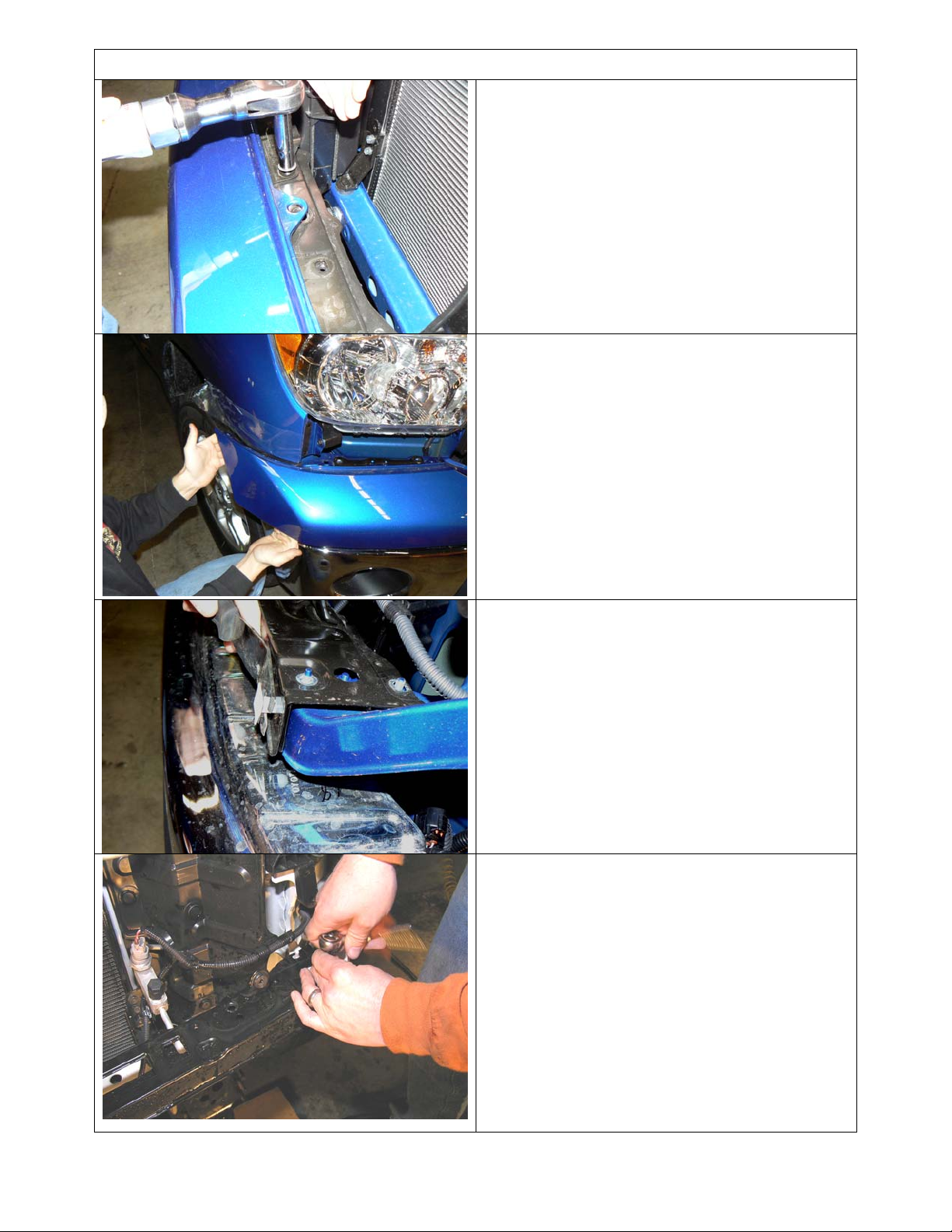
14. Remove screws located along top of cross
member retaining upper bumper metal frame.
Removal of bumper.
15. Pull outward and slightly forward on bumper
cover in upper wheel arch area to unclip tab
on bumper cover from retaining bracket on
fender. The bumper and cover should now
be released. Carefully remove bumper and
set aside.
Hint: This operation is best performed with two
people, one on each end of the bumper.
16. Remove plastic plugs in cross member.
17. Remove cross member and set aside.
Last Rev Date: 29/10/2008 Page 8 of 24 Fitting instructions# 3783321
Copyright © 2005 by ARB Corporation Limited. All rights reserved, this document must not be reproduced without the express authority of ARB Corporation Ltd
Page 9
REMOVAL OF BUMPER
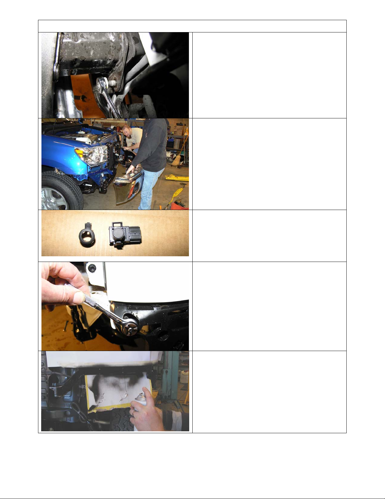
18. Undo crash bar mounts from chassis flange.
19. Remove crash bar and lower bumper
assembly and set aside, retain flange nuts for
reuse.
20. If parking sensors fitted and are to be
reused, remove from bumper. Also retain
loom tails and set aside.
Note: Remove parking sensor centre from
sleeve first. Then remove sleeve from bumper.
21. Remove bumper cover retaining brackets
from the fenders.
22. Mask up and spray paint the exposed metal
trim area black satin, from the wheel arch
right around to the inboard headlamp area as
shown, both sides of the vehicle.
NOTE: This is in the area where the bumper
cover retaining brackets were removed earlier.
When the bull bar is fitted there will be 25mm of
this sheet metal visible, the black painted finish
masks the visible gap.
Last Rev Date: 29/10/2008 Page 9 of 24 Fitting instructions# 3783321
Copyright © 2005 by ARB Corporation Limited. All rights reserved, this document must not be reproduced without the express authority of ARB Corporation Ltd
Page 10
FIT MOUNTING BRACKETS
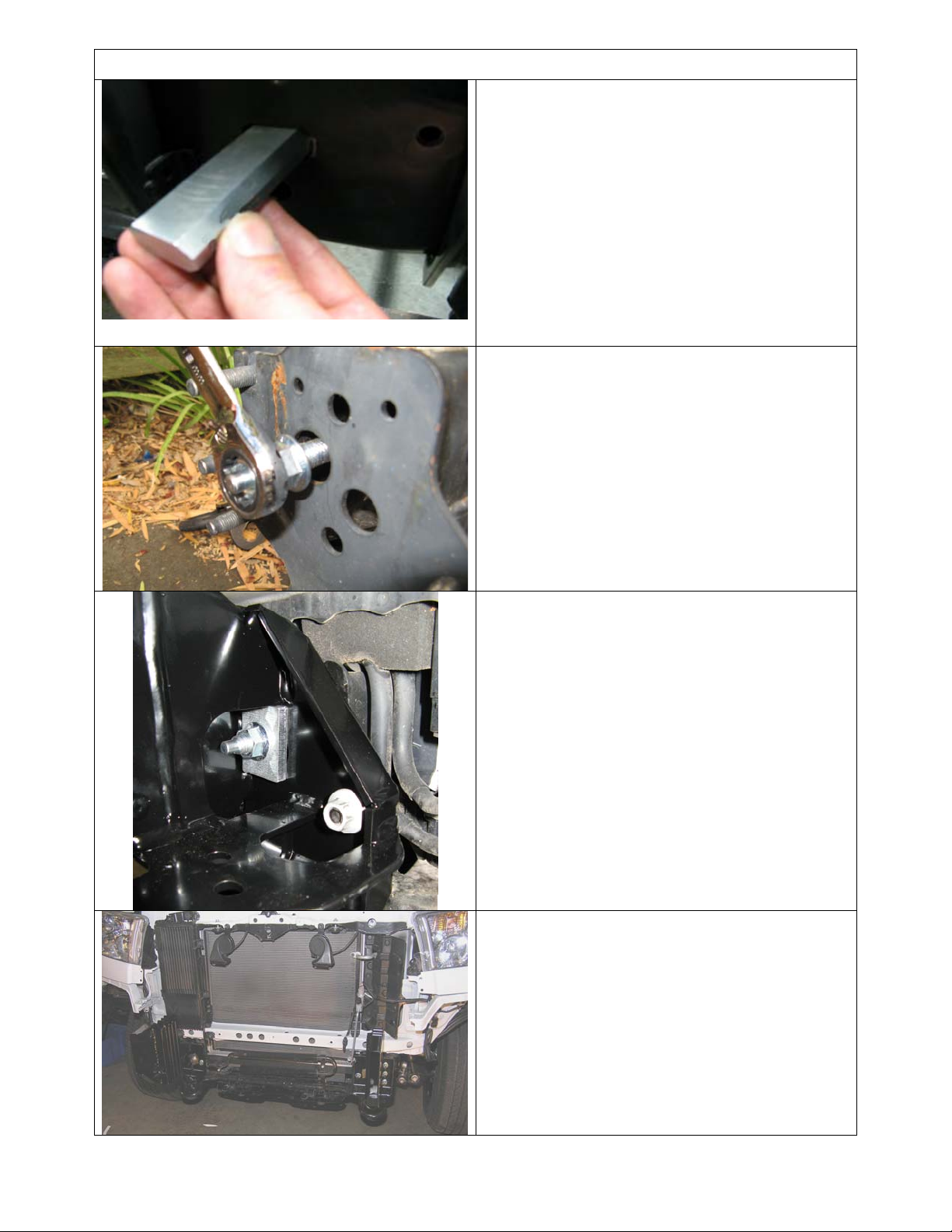
23. Insert clevis nut into rectangular hole in the
inboard face of chassis, ensuring the
threaded end is inserted first.
The nut when fitted correctly should fit square
and locate into the chassis rail.
24. Install the chassis stud by fitting 2 nuts to the
end of the stud and tightening until thread
bottoms out.
25. Remove nuts and repeat for the LHS.
26. Loosely fit the mounting brackets to the
chassis securing with the 8mm packers and
flange nuts.
27. Secure using existing OE M10 flange nuts,
but do not do up tight
.
28. Fit the existing bolts back in tow hooks
but
do not do up tight
Last Rev Date: 29/10/2008 Page 10 of 24 Fitting instructions# 3783321
Copyright © 2005 by ARB Corporation Limited. All rights reserved, this document must not be reproduced without the express authority of ARB Corporation Ltd
Page 11
BAR PREPARATION: FITTING PROCEDURE WINCH
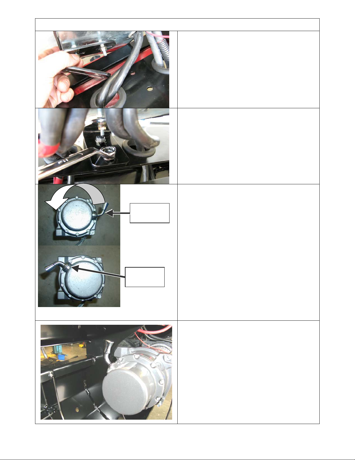
29. Fit large grommets to holes in top pan
30. Fit control box bracket to control box studs
as shown.
Picture also shows routing of
leads through grommets in pan.
NOTE: If 12-15000lb winch is to be fitted, fit off Kit
# 3500120 extra long leads, marking the end of
each one for easy identification for connections to
motor terminals
31. Using M8 fasteners fit control box mounting
bracket to pan
32. Prepare winch for fitting by undoing the cap
screws on the gearbox end.
POSITION
ORIGINAL
POSITION
NEW
33. Then rotate the end cap and gearbox in a
counter clockwise direction 144° ( four hole
pitches) while looking down at the gearbox,
as shown (for 12-15000lb winches rotate
clockwise 72°, two hole pitches)
34. Tighten the cap screws ensuring the gearbox
handle operates freely.
35. For 9500lb only rotate the motor end 90°
clockwise (elec. terminals will be up)
NOTE: Be careful not to lift the gearbox more
than a few millimetres. Before doing up cap
screws, ensure that the flange faces engage
properly and gaskets are not damaged.
36. Position the winch with the mount face facing
upward on an adjustable table or similar and
with the assistance of another person lower
the bulbar over the winch. The winch handle
should be in the LHS of the bull bar for
smaller winches than 12-15000lb winches
which are on the opposite side as they spool
in the opposite direction. The cable must
always spool off the bottom of the winch.
NOTE: Also follow the installation
instructions in the Warn winch handbook
accompanying the winch.
Last Rev Date: 29/10/2008 Page 11 of 24 Fitting instructions# 3783321
Copyright © 2005 by ARB Corporation Limited. All rights reserved, this document must not be reproduced without the express authority of ARB Corporation Ltd
Page 12
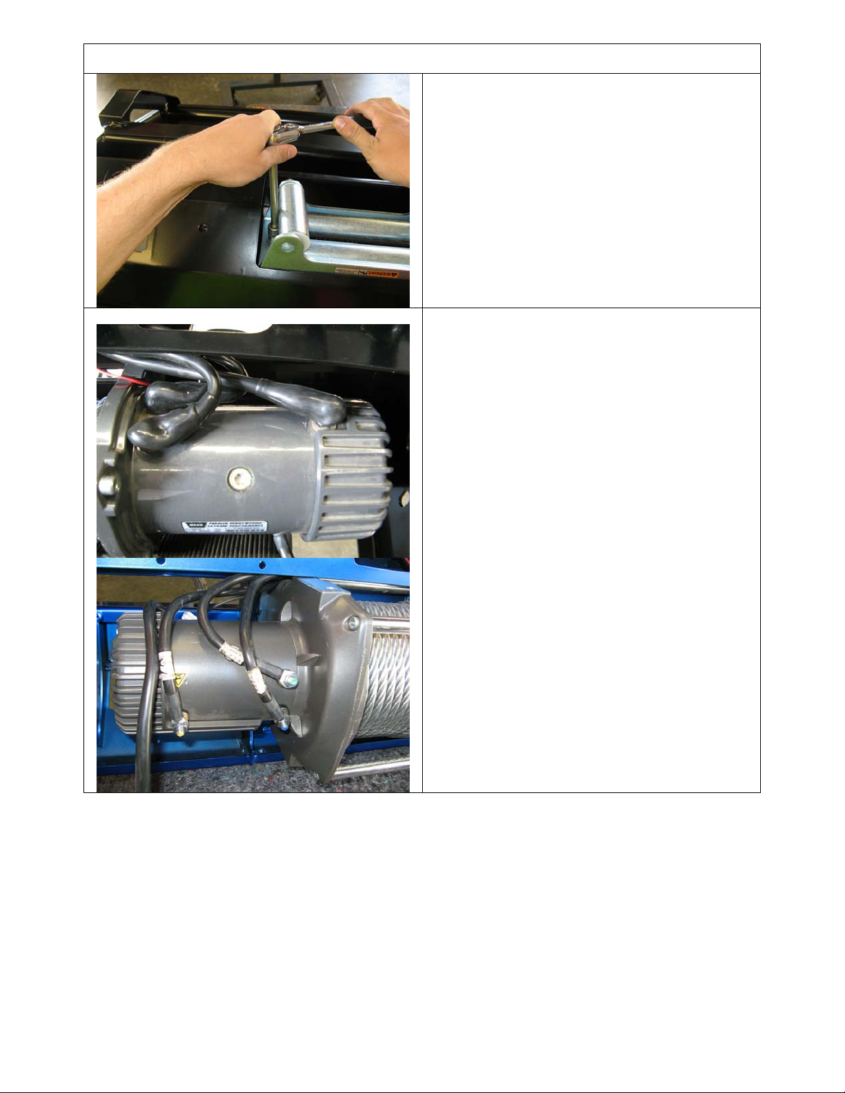
BAR PREPARATION: FITTING PROCEDURE WINCH
37. Fit the roller fair lead, pull only the end of the
cable through and adjust the position of winch
then bolt up securely. Use the 1 ½” long bolts
in the top and 1 ¾”in the lower set through
the RFL.
Hint: To increase access to mount bolts in front of
roller fairlead, remove circlips from bottom of each
vertical roller shaft, push shaft up so roller can be
dislodged sideways. Do up bolts in fairlead and
winch, then refit circlip.
38. With the aid of another person, turn the bull
bar over so that the back of the bar is
accessible.
39. Connect up the wires to the winch per Warn
handbook (9500lb motor shown top 15000lb
lower views)
NOTE: Refer to the Warn winch handbook for
wiring instructions to vehicle.
Last Rev Date: 29/10/2008 Page 12 of 24 Fitting instructions# 3783321
Copyright © 2005 by ARB Corporation Limited. All rights reserved, this document must not be reproduced without the express authority of ARB Corporation Ltd
Page 13
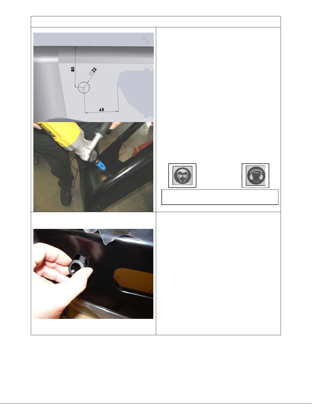
FITTING PROCEDURE BULL BAR PREPARATION
40. If sensors are to be refitted, position the
bar face up and mark out the hole position
as shown on both wings. Dimensioned
80mm from the top of the wing and 65mm
from the most outboard edge of the light
aperture. This position is optimal for
sensor operation.
41. Carefully drill the hole with Dia 22.0mm
(7/8”) hole saw.
CAUTION: Do not make the hole smaller
than shown, Dia 22.0 – 22.3 is ideal.
42. Deburr any sharp edges.
Test fit the sensor sleeve checking that it
43.
fits and is not too tight, the inner bore of
the sleeve must not be reduced in
diameter.
Warning: Drilling operations can result in
flying metal debris, safety glasses should be
Once sensor hole is cut and sensor has
44.
been trial fitted, paint the raw metal edges
to prevent corrosion.
Fit sensor sleeve into bar first as
45.
shown, noting that the tab at rear is up
for RHS of bull bar and down for LHS
(the same orientation as original OE).
Then fit sensor into sleeve.
Fit loom extensions and push anchor
46.
plug into slot in wing brace
Note: Connections are always inboard.
Hint: Take care not to damage sensor
electrical connections when removing and
refitting.
Last Rev Date: 29/10/2008 Page 13 of 24 Fitting instructions# 3783321
Copyright © 2005 by ARB Corporation Limited. All rights reserved, this document must not be reproduced without the express authority of ARB Corporation Ltd
Page 14
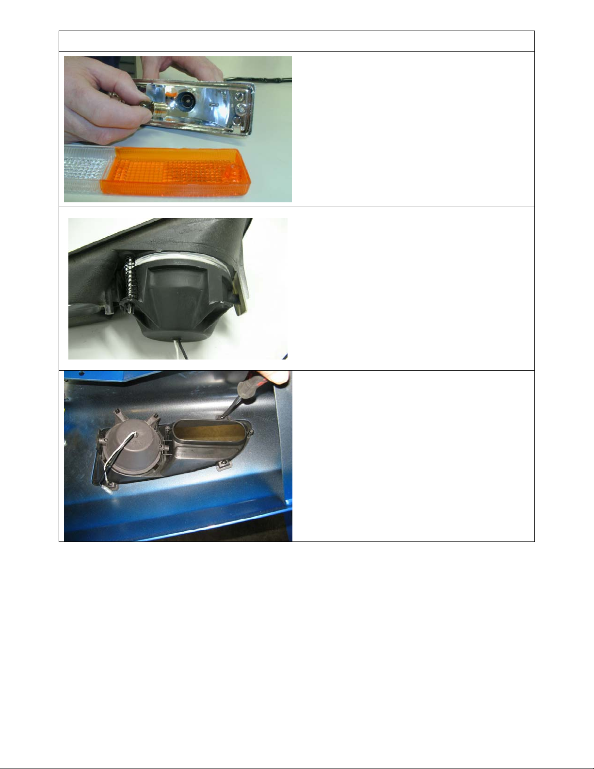
FITTING PROCEDURE BULL BAR PREPARATION
FITTING LIGHT SURROUND ASSEMBLY
Follow fitting instructions supplied with kit.
47. Prior to fitting the supplied indicators, with
lenses temporarily removed, replace 21W
indicator light bulbs (amber reflector side)
with 10W bulbs supplied in fitting kit.
48. If fitting fog lamps, refer to instructions
supplied with kit.
49. Fit the surrounds into the openings in the
wings referring to the fitting instructions with
surround kit.
Last Rev Date: 29/10/2008 Page 14 of 24 Fitting instructions# 3783321
Copyright © 2005 by ARB Corporation Limited. All rights reserved, this document must not be reproduced without the express authority of ARB Corporation Ltd
Page 15
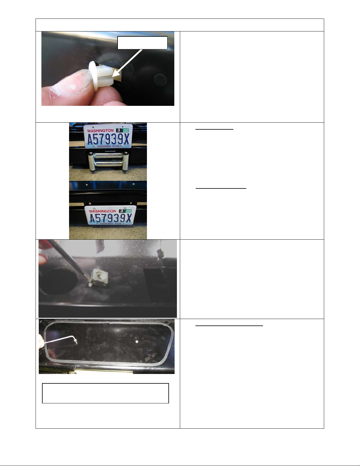
FITTING PROCEDURE BULL BAR PREPARATION
FITTING NUMBER PLATE
Split horizontal
50. If winch fitted, apply double sided tape strip
to top back of number plate. If winch not
fitted, no adhesive strip is required.
51. Fit grommets to slots, with split horizontal as
shown
52. Fit number plate using supplied pan head
screws into grommets.
WITH WINCH
45. Fix using the lower holes in number plate as
shown
WITHOUT WINCH
46. Fix using upper holes in number plate as
shown.
53. In lower inside face of pan, fit M8 cage
nuts for stone tray in four positions as
shown.
Hint: You can use a flat blade screwdriver to
push the remaining cage nut leg into the hole
IF NOT FITTING WINCH
47. Wrap rubber extrusion around winch cover,
trim to length.
48. Place M6 st stl flat washers over holes in the
top face of the bull bar where the winch cover is
fixed to the bull bar.
NOTE: The M6 washers support the cover and
The narrower section of the plate is to front
of bull bar
prevent dipping around the screw heads
49. Place the winch cover in position as shown with
screws aligning through the mount holes and
.
leaving the washers in place.
50. Bolt together using the M6 button head
stainless steel screws, washers and M6 nuts.
Last Rev Date: 29/10/2008 Page 15 of 24 Fitting instructions# 3783321
Copyright © 2005 by ARB Corporation Limited. All rights reserved, this document must not be reproduced without the express authority of ARB Corporation Ltd
Page 16
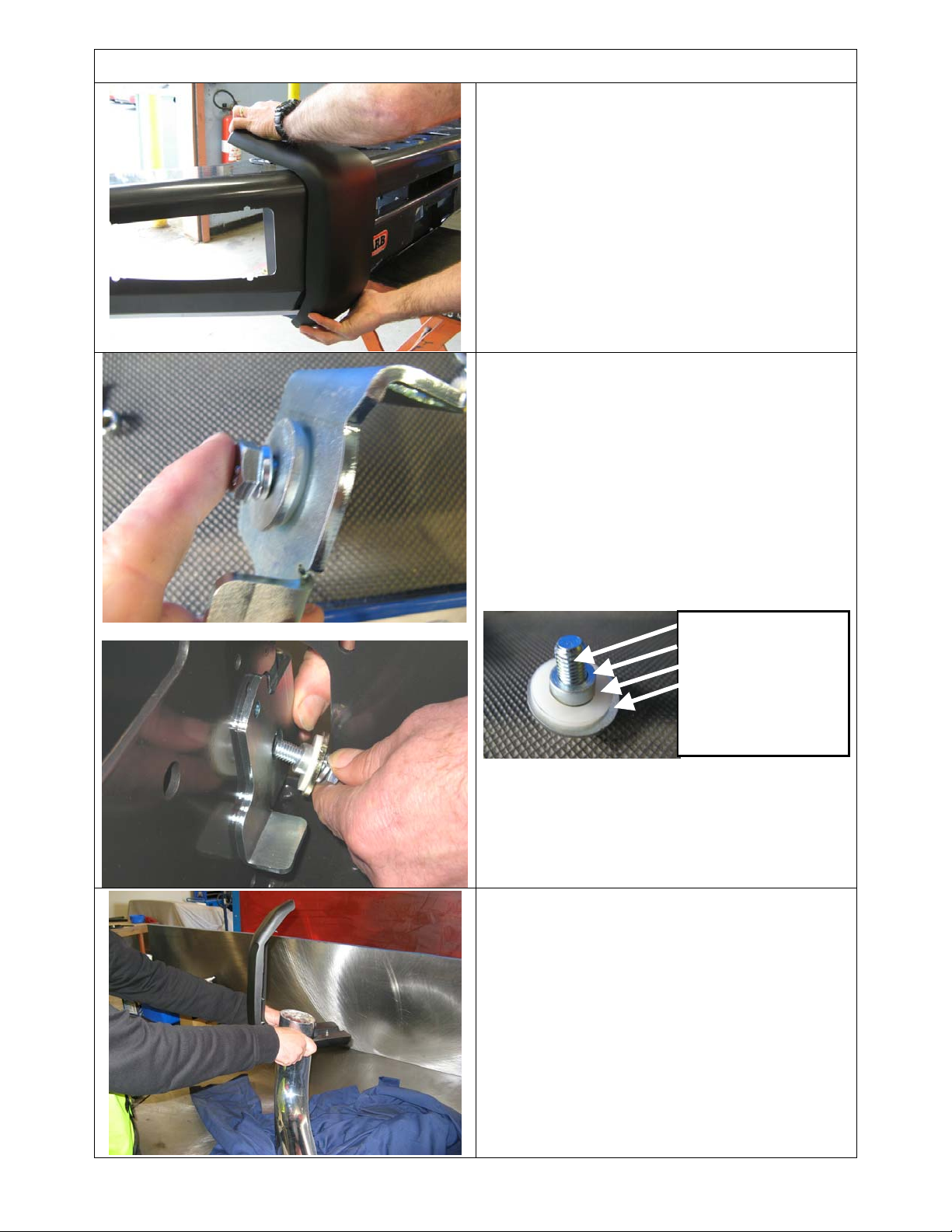
FITTING BUFFERS or BUFFERS WITH FRAME
BUFFERS ONLY
51. With sahara bar sitting as it would when fitted
to vehicle, fit each buffer in turn and secure
with M6 flange nuts on 6 x studs per side
once buffers are carefully pushed home
against the profile of the bull bar be careful
not to over tighten the flange nuts as damage
to buffer can result.
BUFFERS AND FRAME
52. Place the sahara bar face down on a soft
surface
53. Fit the RH hinge bracket assembly to
outboard side of upright as shown, with M10
bolt, large M10 washer, spring washer, flange
nut, bush and 16mm ID nylon washer.
Tighten to recommended torque.
NOTE: The top flange of hinge bracket must face
inboard, ie top flanges are towards each other
when fitted
54. Repeat for LHS.
M10 x 30 bolt
Spacer bush
M16 nylon washer
Large M10 washer
NOTE: When the frame sits on the bumper, it is
angled backward. Put it up against the bumper
and determine which side is LH and RH. The
buffers are handed RH and LH. Select the
correctly handed buffer to fit over each end of
the frame before proceeding.
55. Slide the buffers over the frame as shown
Last Rev Date: 29/10/2008 Page 16 of 24 Fitting instructions# 3783321
Copyright © 2005 by ARB Corporation Limited. All rights reserved, this document must not be reproduced without the express authority of ARB Corporation Ltd
Page 17
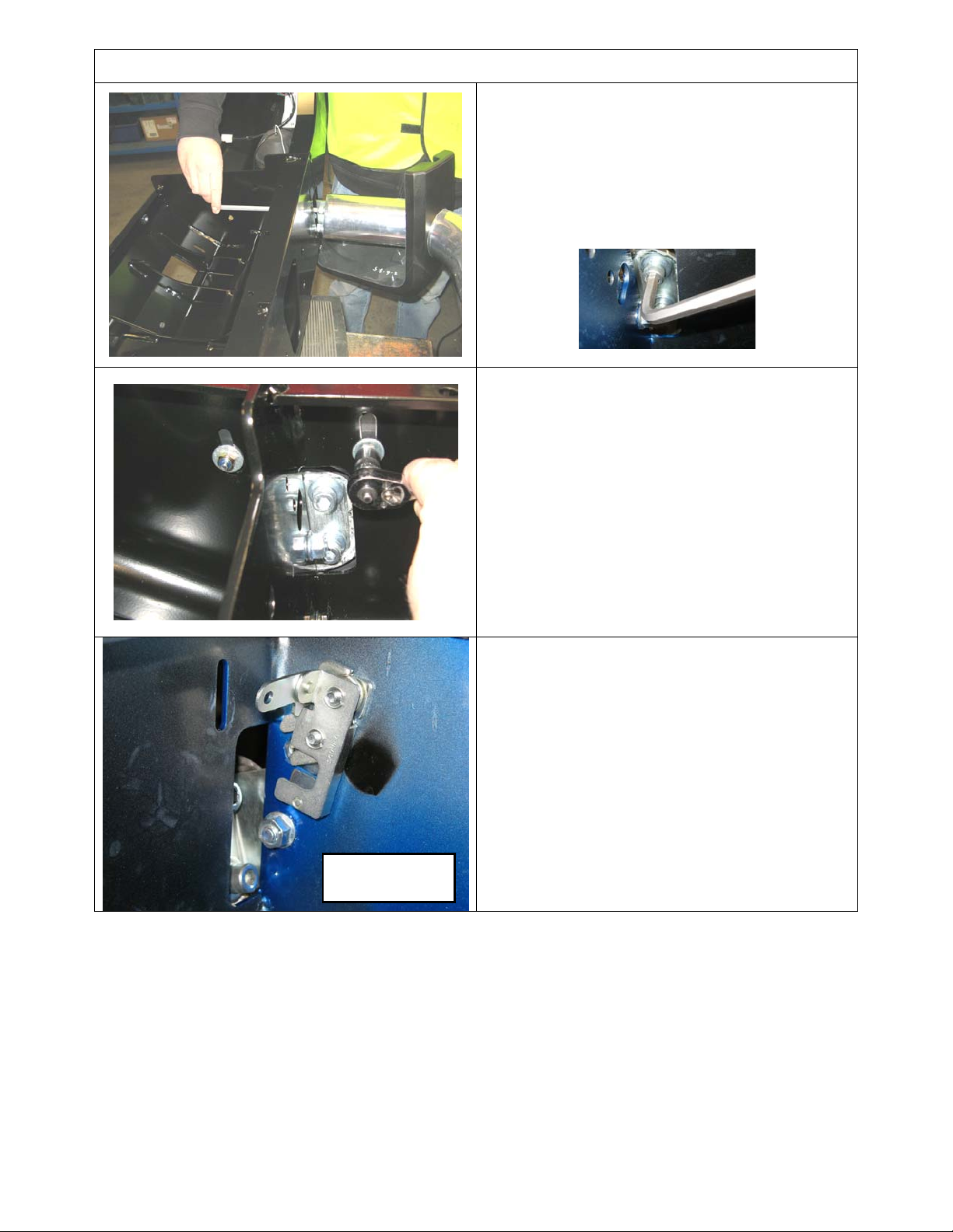
FITTING BUFFERS WITH FRAME
56. Fix the frame to the hinge brackets using 4 x
sets M10 x 30 Cap Screws, flat and spring
washers
57. Ensure that the frame is centred on the
brackets and bar assembly
58. Tighten the cap screws to recommended
torque
59. Slide the buffers down over the frame and
secure using M6 flange nuts on the four lower
buffer studs on each buffer and M6 nyloc nuts
with large M6 flat washers on the two studs
located on top face.
CAUTION: Do not over tighten nuts as damage
to buffer can result
NOTE: The latching assembly is only
fitted to RHS of the bumper
60. Fit the slam latch assembly to
side of upright) secure using ¼ UNC x 1”
bolts, flat and spring washers.
to rear of bumper.
61. Tighten firmly, to 14Nm (11lbft).
(inboard
RHS
Lever arm is
View from
inside bumper
Last Rev Date: 29/10/2008 Page 17 of 24 Fitting instructions# 3783321
Copyright © 2005 by ARB Corporation Limited. All rights reserved, this document must not be reproduced without the express authority of ARB Corporation Ltd
Page 18
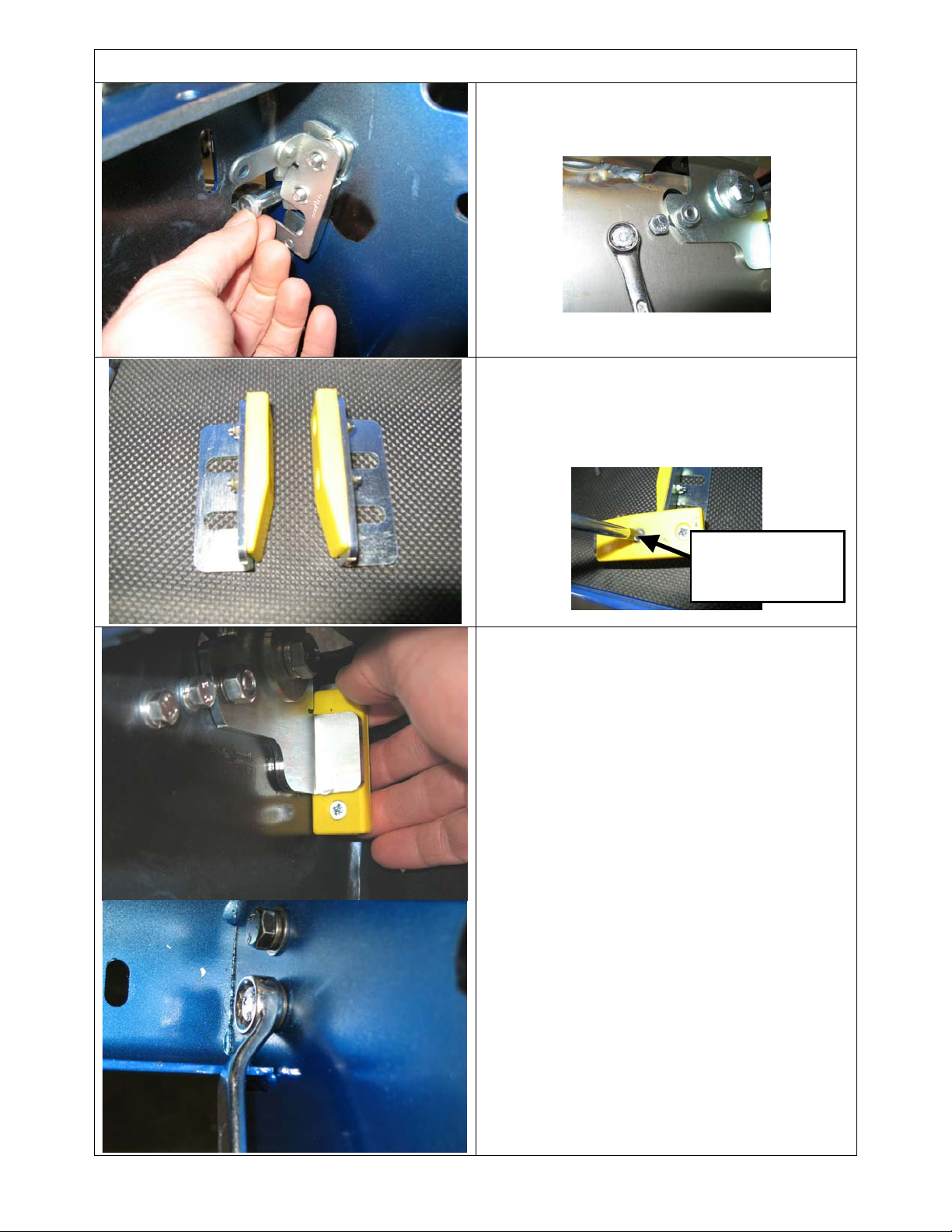
FITTING BUFFERS WITH FRAME
62. Fit the striker pin to the RHS hinge plate and
secure with 5/16”UNC nut and spring washer
as shown and tighten to 22Nm or 16lbft
63. Fit a urethane buffer pad to each of the right
angle brackets using M4x16 csk head screws
and M4 nyloc nuts, to create a pair of RH and
LH assemblies as shown.
64. Tighten the screws until the heads are 1.5mm
below the face of the urethane pad
Screw in until
head is below
surface by 1.5mm
65. Fit the RHS buffer pad assembly as shown,
wedge of pad up. Secure with 2 x M8 bolts,
washers and flange nut sets. Load bolts from
inboard side of upright, nuts are on bracket
side.
66. With the striker pin engaged fully in the latch
and a slight amount of pressure on the frame
pushing it back against the slam latch, pull
the pad hard against the hinge bracket flange
as shown.
67. Tighten the M8 bolts to recommended torque.
68. Repeat for the LHS
The intention once the assembly is
complete is for the frame to feel solid
without any play.
Last Rev Date: 29/10/2008 Page 18 of 24 Fitting instructions# 3783321
Copyright © 2005 by ARB Corporation Limited. All rights reserved, this document must not be reproduced without the express authority of ARB Corporation Ltd
Page 19
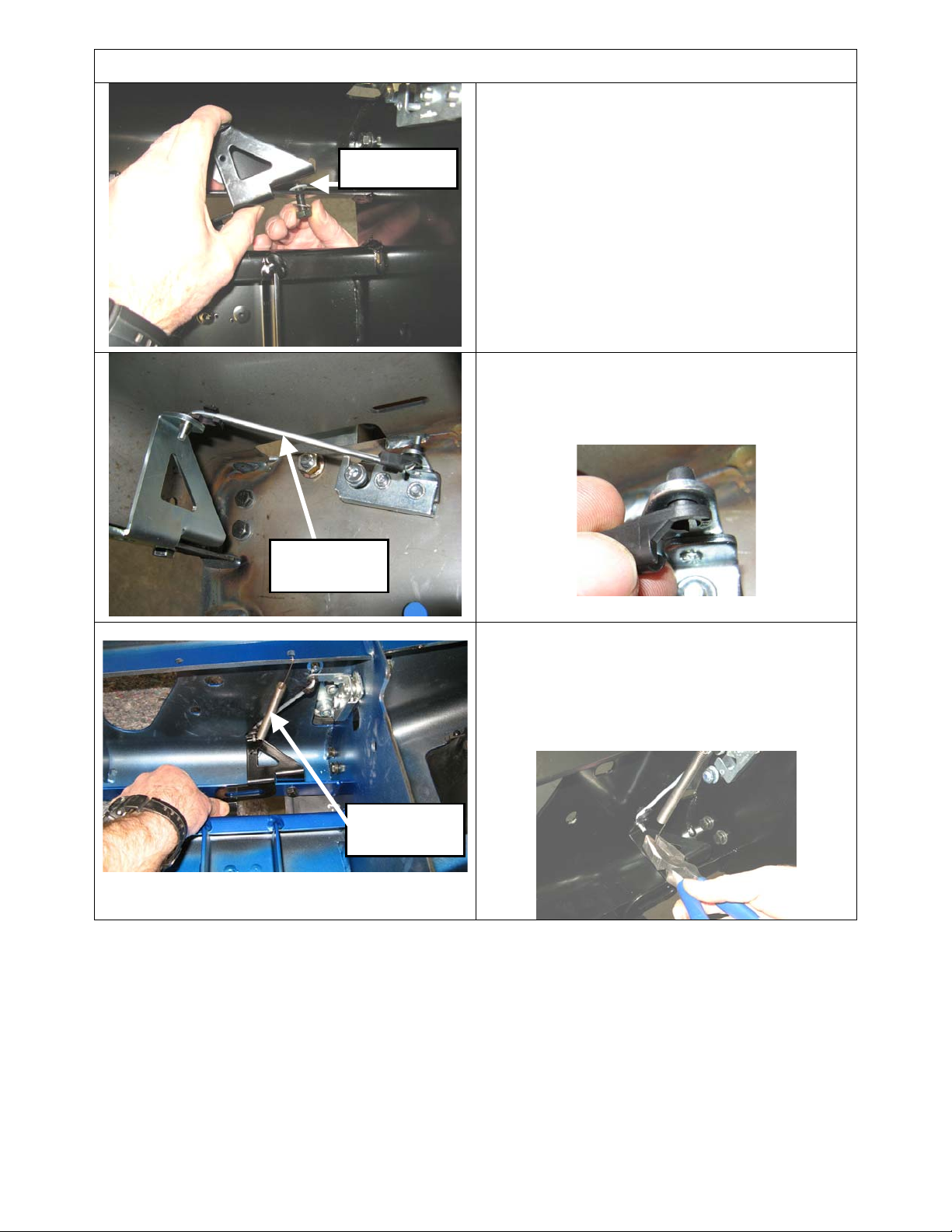
FITTING BUFFERS WITH FRAME
69. Fit the lever bracket for the slam latch
operation using an M8 x 25 black bolt, nyloc
nut, 2 x M8 flat washers and nylon washer
sandwiched between the pan flange
.
Nylon
which is
and face of bracket at pivot point
70. Once M8 nyloc nut is tensioned, bracket must
be able to pivot freely, without play and
without rubbing contact with mounting flange,
adjust accordingly.
71. Fit the plastic rod connector fittings from
underneath into the lever in the slam latch
and from above into the operating bracket
72. Fit the 4mm link rod
Link rod
73. Fit the spring as shown. It connects to the
lever bracket through the hole in the side and
to a hole in the pan brace at the rear of the
top pan
74. Crimp over the end loops to secure the spring
ends in position
Spring
Last Rev Date: 29/10/2008 Page 19 of 24 Fitting instructions# 3783321
Copyright © 2005 by ARB Corporation Limited. All rights reserved, this document must not be reproduced without the express authority of ARB Corporation Ltd
Page 20
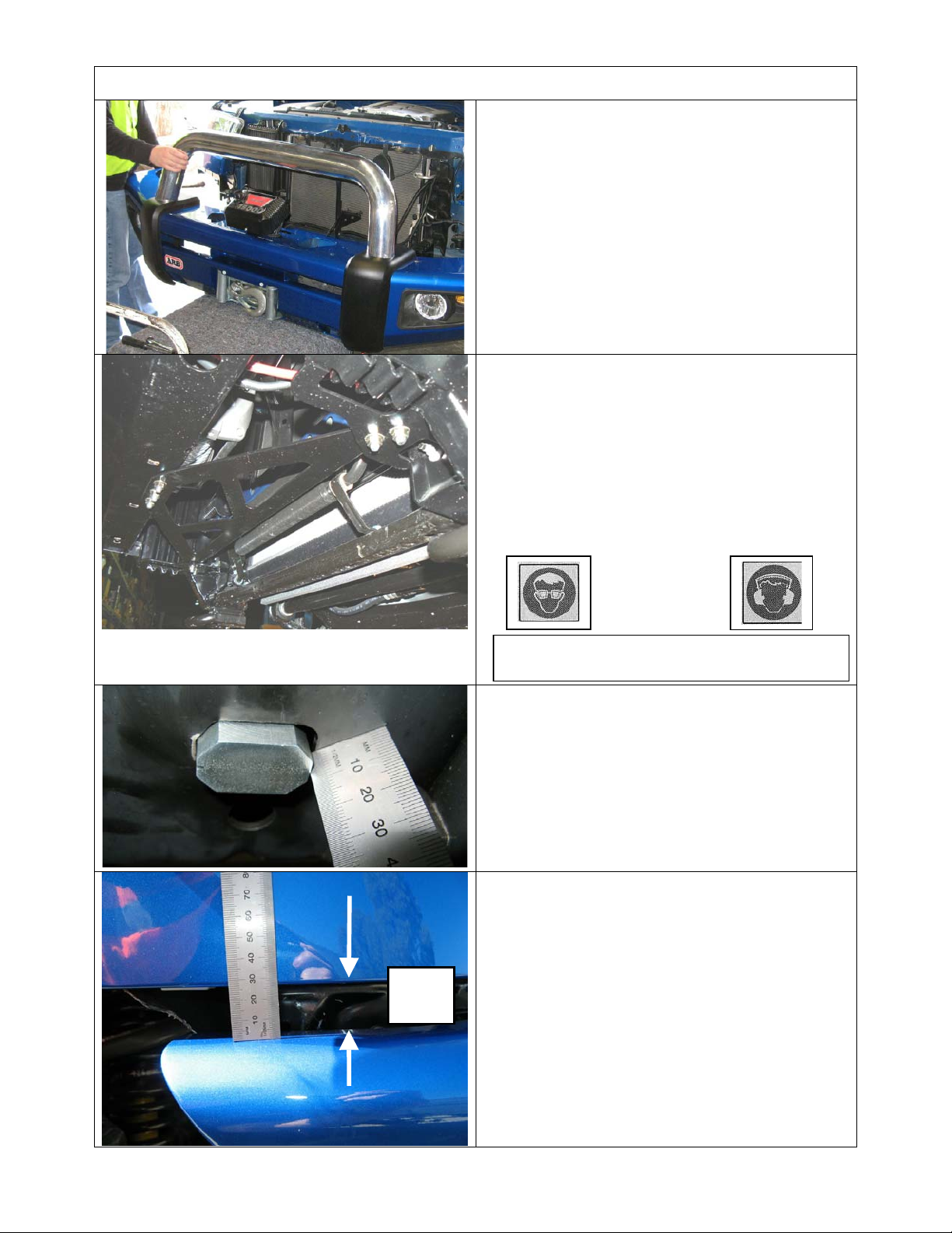
FITTING PROCEDURE BAR ON VEHICLE
75. Using two people, three if winch fitted,
position the bar assembly on the vehicle
mounts.
Caution: This product is heavy, especially if a
winch is fitted. Do not attempt to lift it and fit it
by yourself. Have some assistants help you or
use a mechanical aid such as a hydraulic lift
table.
76. Bolt the bar to the mounts using M12 bolts.
Large flat washers and spring washers.
Centralise the bar to the front of the vehicle.
Do not tighten any bolts yet
77. Fit the cross brace to underside of lower pan
and on top of gussets in mount brackets. Use
M10 x 30mm SEMS bolt and washer sets,
flange nuts but do not do up tight. If holes in
pan do not line up, run a Dia 10.0 drill through
any holes to enable bolt entry.
25mm
gap
Warning: Drilling operations can result in
flying metal debris, safety glasses should be
78. Tighten up the mount brackets fasteners.
Start with the tow hook bolts, then M10 flange
nuts to chassis studs.
79. Then tighten up the long M12 chassis studs,
ensuring that the clevis nut is positioned
correctly over the hole in the chassis.
NOTE: Protrusion as shown is approximately
7mm.
80. Adjust the bar height leaving approximately
25mm gap between top of wing to fender.
Align the bar so the front face is vertical and
the gap is even on both sides of the vehicle.
Last Rev Date: 29/10/2008 Page 20 of 24 Fitting instructions# 3783321
Copyright © 2005 by ARB Corporation Limited. All rights reserved, this document must not be reproduced without the express authority of ARB Corporation Ltd
Page 21
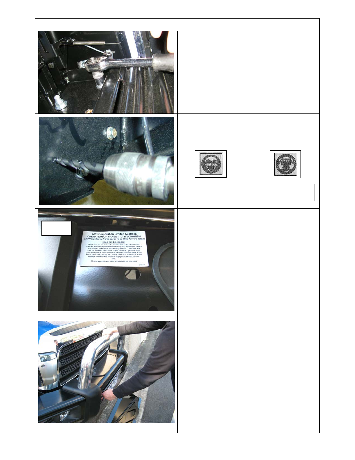
FITTING PROCEDURE BAR ON VEHICLE
81. Tighten M12x 40mm mounting bolts to
recommended torque
82. Tighten up the M10 brace bolts in 7 places to
recommended torque
64. Using the M10 pilot hole in mount brackets,
drill pinning hole through uprights of bull bar.
Fit M10 SEMS bolt and flange nut, do up tight
to recommended torque.
Buffer
Warning: Drilling operations can result in
flying metal debris, safety glasses should be
83. Apply the frame tilt operation label to the top
face of the pan adjacent to the buffer as
shown in diagram
WARNING: LABEL FOR FRAME TILT
OPERATION FOR HOOD CLEARANCE MUST
BE APPLIED TO TOP FACE OF SAHARA
BUMPER IN THE POSITION IDENTIFIED IN
THESE FITTING INSTRUCTIONS. FAILURE TO
APPLY THIS PERMANENT LABEL AT SAHARA
BUMPER FITMENT INDEMNIFIES ARB
CORPORATION OF ANY LIABILITY ARISING
FROM THE OPERATION OR USE OF THIS
PRODUCT.
65. Test the operation of the frame tilt assembly
66. Frame should release from latch and engage
as per the supplied label.
If necessary, adjust the slam latch and or the
bump stops to ensure that the frame complies
and does not have any free play when latched
in the home position yet releases to come
forward with slight backward pressure on top
of tube when lever is pulled forward
.
WARNING: THIS FRAME IS NOT DESIGNED
TO SUSTAIN EXCESS LOADING EITHER
FORWARDS OR BACKWARDS, SUCH
LOADS MAY DAMAGE THE FRAME
ASSEMBLY TILT MECHANISM
Last Rev Date: 29/10/2008 Page 21 of 24 Fitting instructions# 3783321
Copyright © 2005 by ARB Corporation Limited. All rights reserved, this document must not be reproduced without the express authority of ARB Corporation Ltd
Page 22
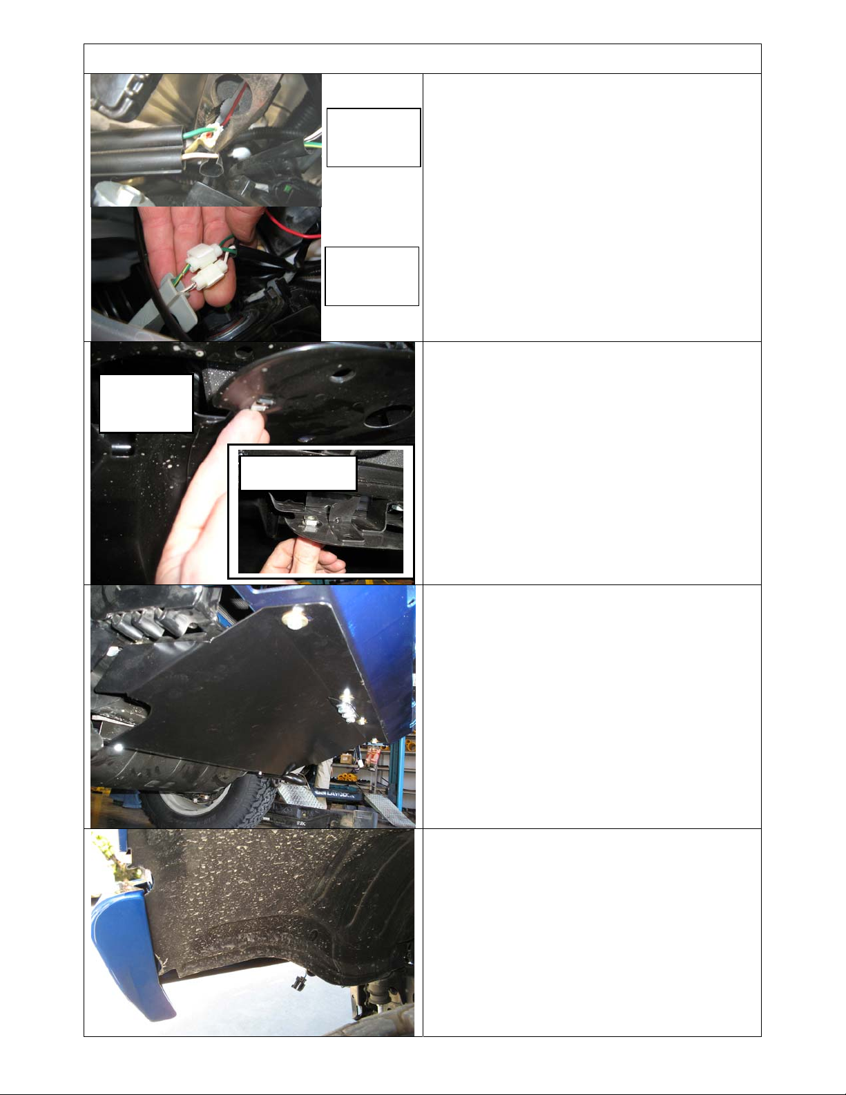
View from
underneath
FITTING PROCEDURE BAR ON VEHICLE
54. Wire up indicators and parking lamps.
Note:
Running
lamp wiring
Indicator
lamp wiring
Wire configuration of supplied indicator looms;
Black = ground
Green = indicator (amber)
Red = run lamp (clear)
55. Use supplied scotch locks for the electrical
connections then secure wiring with cable ties
when complete.
56. Wire up P# 6821201 ARB fog lamps if fitted.
NOTE: For vehicles without factory fog lamp loom,
use ARB Loom MD02 plus switch. Supplied tails
can be joined to OE loom
77. Using square file, increase slot length in 2 x
existing holes in sump guard (those pitched
570mm apart) to a size of 12.3mm A/F.
78. Fit two M8 cage nuts to slots in sump guard
(NOTE: nut body above panel as shown).
View from top
79. Fit stone tray using 4 x M8 bolts and washer
sets at front and 2 x M8 bolts, washers and
into fitted M8 cage nuts at two locations into
existing sump guard front section as shown.
72. Trim fender liner if required. Tuck behind
wing return.
73. If required secure with cable ties through
holes in bulkhead.
Last Rev Date: 29/10/2008 Page 22 of 24 Fitting instructions# 3783321
Copyright © 2005 by ARB Corporation Limited. All rights reserved, this document must not be reproduced without the express authority of ARB Corporation Ltd
Page 23
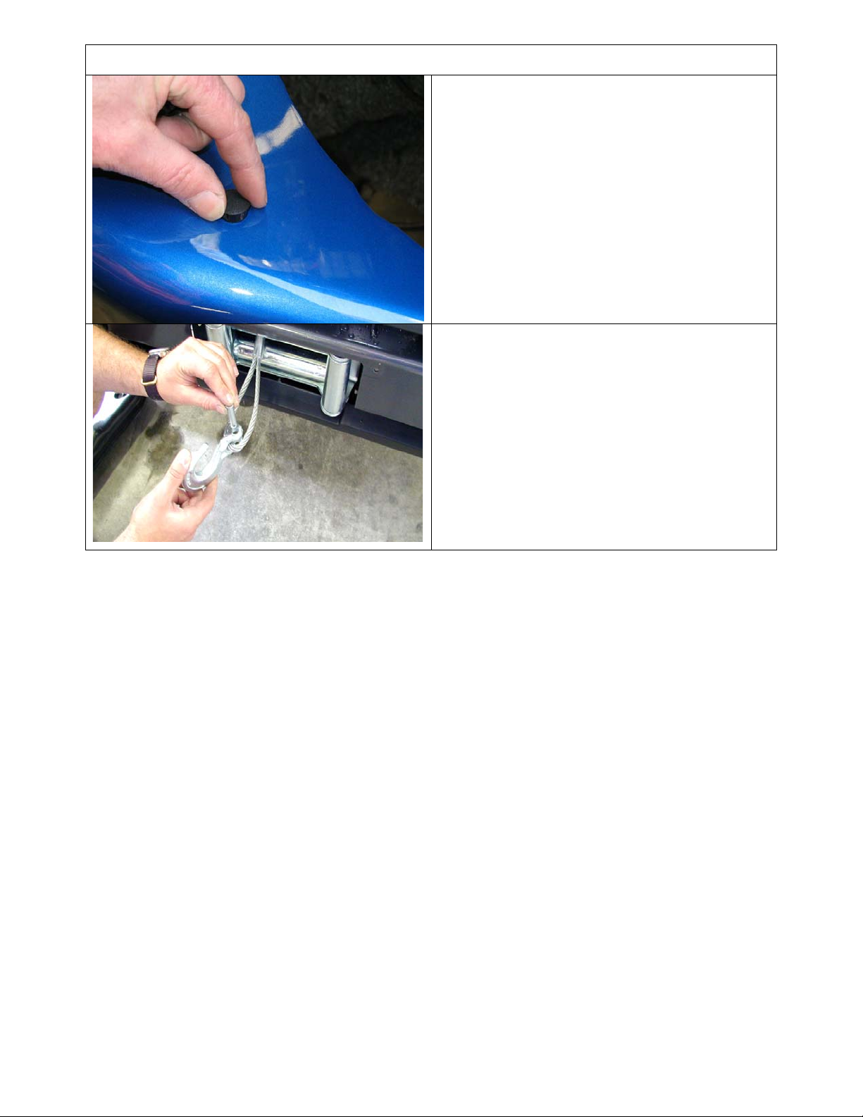
FITTING PROCEDURE BAR ON VEHICLE
80. Unless fitting CB aerials, fit blanking plugs in
provided holes in the top of the wings.
81. If winch fitted, fit off winch hook.
Last Rev Date: 29/10/2008 Page 23 of 24 Fitting instructions# 3783321
Copyright © 2005 by ARB Corporation Limited. All rights reserved, this document must not be reproduced without the express authority of ARB Corporation Ltd
Page 24
NOTE:
♦
♦
♦
♦
♦
♦
♦
Connect wiring to fitted sensors, lights and winch.
Check that wiring does not contact sharp edges and piping etc is clear of moving
parts by at least 15mm
Check operation of all lights.
Check operation of parking sensors. If sensors do not function correctly refer to
appropriate section in notes.
Adjust fog lamp beam aim.
Check winch operation
If fitted check frame tilt operation
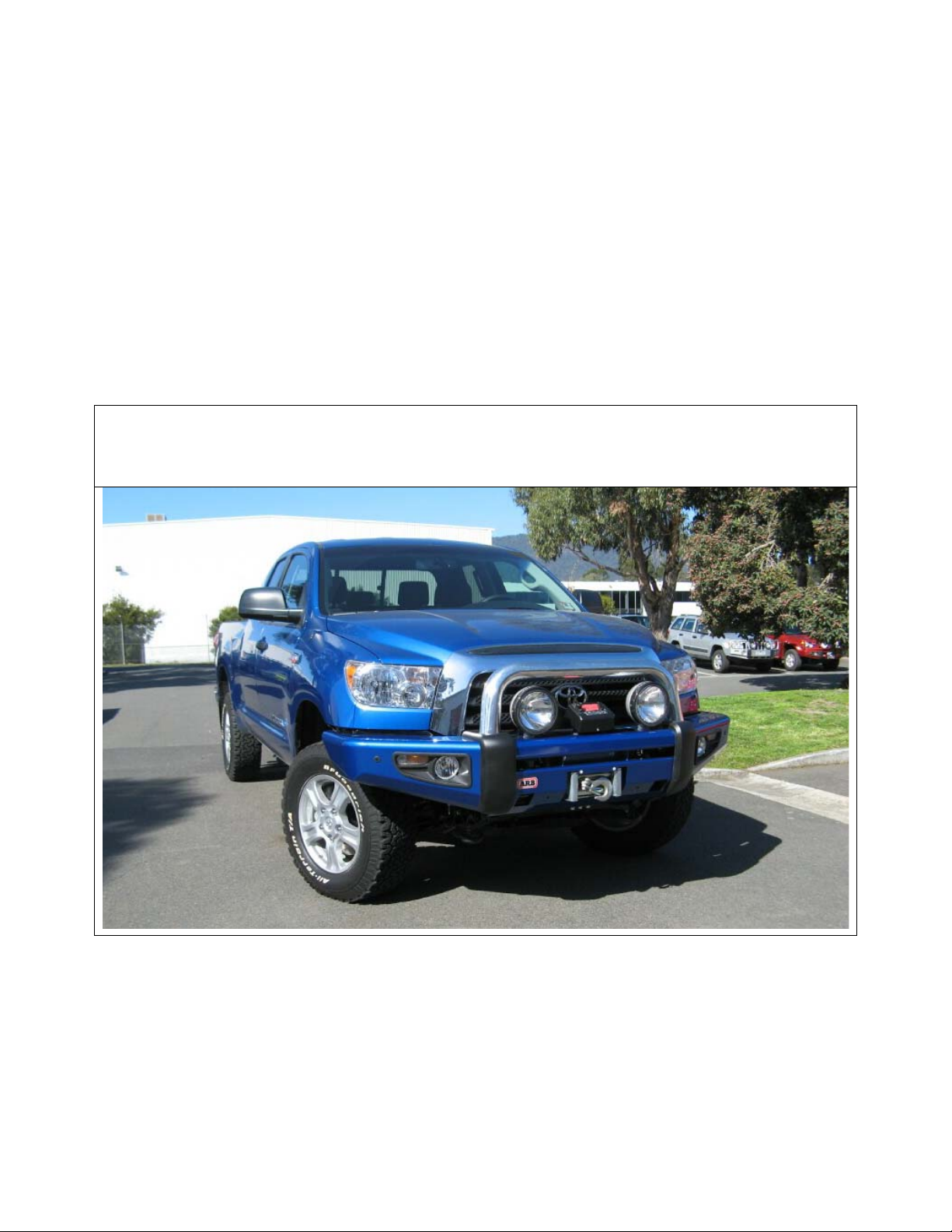
FITTED PRODUCT
Last Rev Date: 29/10/2008 Page 24 of 24 Fitting instructions# 3783321
Copyright © 2005 by ARB Corporation Limited. All rights reserved, this document must not be reproduced without the express authority of ARB Corporation Ltd
 Loading...