

Page 1
DEC 2001 Page 1 of 6 3782513
If you have any queries regarding the installation of this product please contact the distributor from whom it was purchased, or alternatively the ARB office in your state.
Head Office – ARB Corporation Ltd VIC: 42-44 Garden Street, Kilsyth, Victoria, 3137 Tel: (03) 9761 6622 Fax: (03) 9761 6807
WA: (08) 9244 3553 NSW: (02) 9821 3633 ACT: (02) 6280 7475 SA: (08) 8244 5001 QLD: (07) 3872 3872 NT: (08) 8947 2262 TAS: (03) 6331 4190
LAND ROVER DISCOVERY No 32/3432050
DELUXE AND WINCH BULL BARS
(JANUARY 1995 ONWARD)
WARNING
FOR VEHICLES EQUIPPED WITH SRS AIRBAG
WHEN INSTALLED IN ACCORDANCE WITH THESE INSTRUCTIONS, THE FRONT
PROTECTION BAR DOES NOT AFFECT OPERATION OF THE SRS AIRBAG.
TAKE NOTE OF THE FOLLOWING:
• THIS PRODUCT MUST BE INSTALLED EXACTLY AS PER THESE
INSTRUCTIONS USING ONLY THE HARDWARE SUPPLIED.
• DO NOT USE THIS PRODUCT FOR ANY VEHICLE MAKE OR MODEL,
OTHER THAN THOSE SPECIFIED BY ARB.
• DO NOT REMOVE LABELS FROM THIS BULL BAR.
• THIS PRODUCT OR ITS FIXING MUST NOT BE MODIFIED IN ANY WAY.
Page 2
25-9-98 Page 2 of 6 3782513
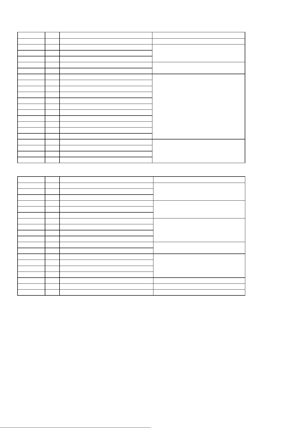
FITTING KIT (TO SUIT BOTH BULL BARS) No. 6171239
PART No
QTY
DESCRIPTION
USE
3500080
1
INDICATOR KIT (contains L and R)
TURN SIGNAL INDICATORS
6151017
2
M6 X 16mm BOLT
NUMBER PLATE TO BULL BAR
6151046
2
M6 FLAT WASHER
6151128
2
M6 FLANGE NUT
3500200
1
BUFFER KIT
RUBBER BUFFER TO BULL BAR
3751627L
1
IMPACT ABSORBER (LHS)
IMPACT ABSORBERS AND
3751627R
1
IMPACT ABSORBER (RHS)
MOUNT ASSEMBLY TO CHASSIS
5846273
2
CHASSIS PACKER INSIDE
5846274
2
CHASSIS PACKER OUTSIDE
6151105
4
1/2" X 4 1/2" BOLT
6151106
2
1/2" X 5" BOLT
4581007
2
40mm HEAVY DUTY WASHER
4581050
6
1/2" SPRING WASHER
4581049
10
1/2" FLAT WASHER
6151138
6
1/2" NUT
180302
1
CABLE TIE
6151087
8
M10 X 25mm BOLT
BULL BAR TO IMPACT ABSORBER
4581048
8
M10 SPRING WASHER
4581039
16
M10 FLAT WASHER
6151033
8
M10 X 1.25 NUT
ADDITIONAL FITTING KIT FOR THE WINCH BULL BAR No. 6171223
PART No
QTY
DESCRIPTION
USE
6151118
2
1/4" NUT
CONTROL BOX TO CONTROL BOX
4581035
2
M6 FLAT WASHER
BRACKET:
4581036
2
M6 SPRING WASHER
(A) For 8 or 9,000lb winch
6151118
4
1/4" NUT
CONTROL BOX TO CONTROL BOX
6151068
2
1/4" X 1" BOLT
BRACKET:
4581036
4
M6 SPRING WASHER
(B) For 10,000lb winch
3751619
1
CONTROL BOX BRACKET
CONTROL BOX BRACKET
6151021
2
M8 X 20mm BOLT
TO BULL BAR
4581044
2
M8 FLAT WASHER
6151132
2
M8 FLANGE NUT
BLR850
1
WIRING LOOM RED
CABLES 10,000lb WINCH ONLY
BLB850
2
WIRING LOOM BLACK
(supplied with winch guard)
6151094
2
M12 X 30 mm BOLT
ROLLER FAIRLEAD TO BULL BAR
4581050
2
1/2" WASHER SPRING
4581049
4
1/2" WASHER FLAT
6151135
2
M12 X 1.25 NUT
4601021
1
WINCH MOUNT CRADLE
WINCH MOUNT CRADLE TO CHASSIS
4581040
4
3/8” FLAT WASHER
WINCH 8 OR 9,0000lb ONLY
4581042
4
7/16” WASHER FLAT
WINCH 10,0000lb ONLY
Page 3
25-9-98 Page 3 of 6 3782513
TOOLS REQUIRED
Basic tool kit, level, tape measure, drill and 1/2” drill bit.
FITTING PROCEDURE
1. Disconnect the headlight washers at the T piece by cutting the tube, take care as the T piece is fragile.
NOTE: First temporarily block the tube to prevent loss of washer fluid.
2. Remove the bumper bar.
3. Remove the headlight washers and tubing from the bumper bar and fit to the bull bar. Make sure the tubing is fed
through the holes in the bull bar upright.
4. Fit the turn signal indicators supplied into the bull bar. NOTE: Refer to the instructions supplied with the turn
signal indicator kit.
5. WINCH BARS: FITTING THE 8 OR 9,000lb WINCH
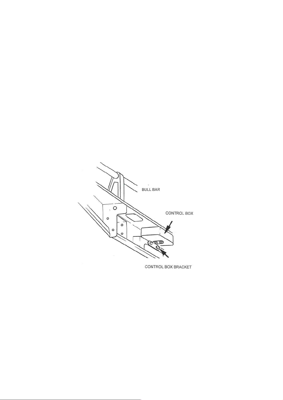
A. Fit the control box to the control box bracket using the two 1/4” nuts, washers and spring washers. Bolt the
control box bracket to the bull bar using the M8 x 20mm bolts, flat washers and flange nuts supplied.
DIAGRAM 1
Page 4
25-9-98 Page 4 of 6 3782513
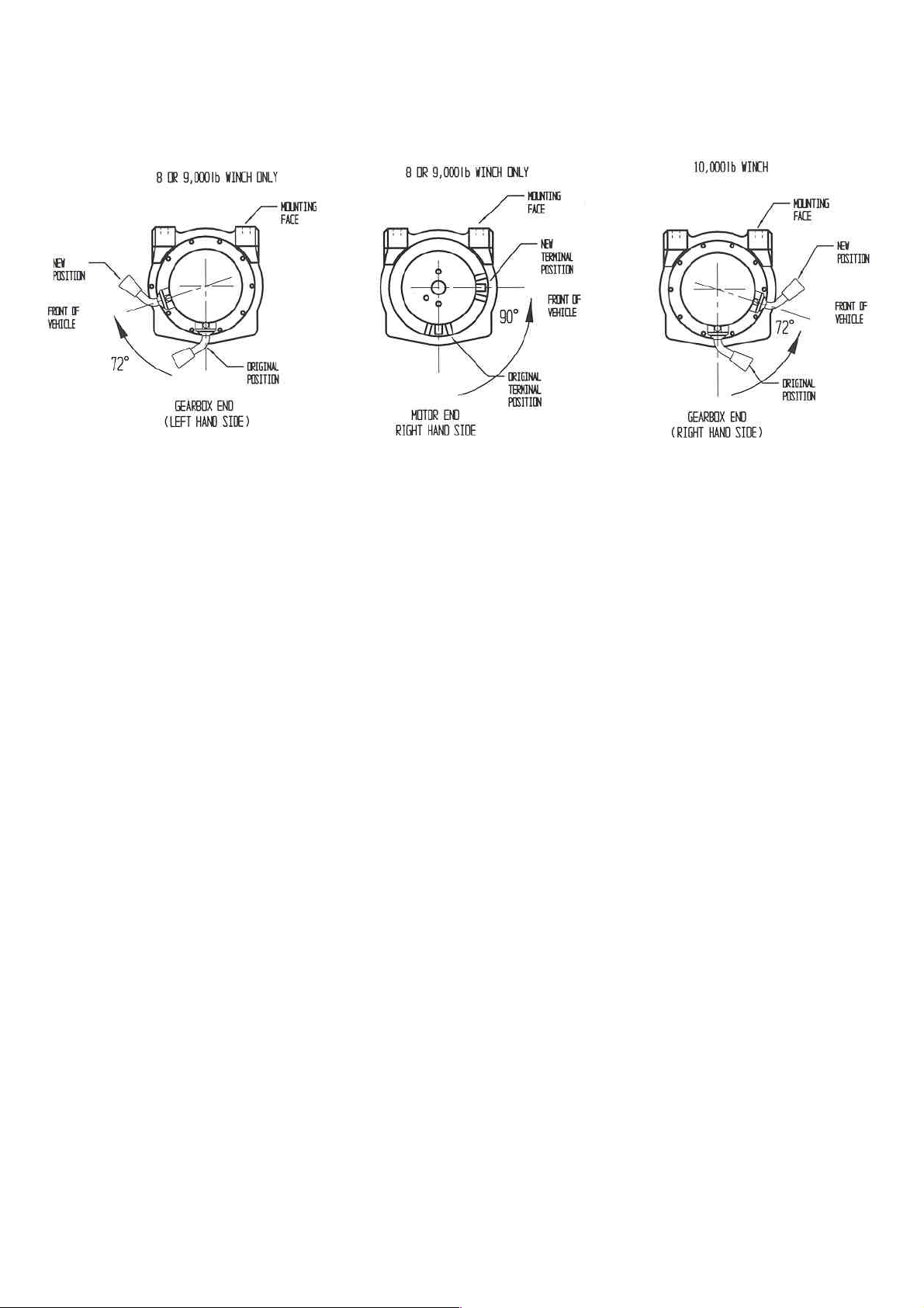
B. To place the winch clutch handle in a convenient location, the winch gearbox must be rotated 2 hole spacings,
72 degrees, in a clockwise direction when viewed from the gearbox end. Place the winch on its end and
remove all gearbox bolts. Gently raise the gearbox just enough to rotate it. Do not completely remove the
gearbox and avoid damaging the gasket. Refit all bolts and tighten.
DIAGRAM 2A DIAGRAM 2B DIAGRAM 2C
C. To place the winch motor in the correct location, the winch motor must be rotated 90 degrees, in an anti-
clockwise direction when viewed from the motor end. Place the winch on its end and remove the 2 motor
retaining bolts. Gently raise the motor just enough to rotate it. Do not completely remove the motor and avoid
damaging the gasket. Refit all bolts and tighten. Refer to diagram 2B.
D. Fit the roller fairlead into the front of the bull bar using the M12 x 30mm bolts, flat washers, spring washers
and nuts supplied.
5. WINCH BARS: FITTING THE 10,000lb WINCH
A. Remove the cover of the control box, disconnect the two heavy short black cables and the heavy short red
cable and replace with the corresponding cables supplied. Insert the two 1/4” x 1” bolts into the base of the
control box and fix in place with 1/4” nuts, flat washers and spring washers. Replace the cover, then fit the
control box to the control box bracket using the two 1/4” nuts, washers and spring washers. Then bolt the
control box bracket to the bull bar using the M8 x 20mm bolts, flat washers and flange nuts supplied. Refer to
diagram 1.
B. To place the winch clutch handle in a convenient location, the winch gearbox must be rotated 2 hole spacing,
72 degrees, in a anti clockwise direction when viewed from the gearbox end. Place the winch on its end and
remove all gearbox bolts. Gently raise the gearbox just enough to rotate it. Do not completely remove the
gearbox and avoid damaging the gasket. Refit all bolts and tighten. Refer to diagram 2C.
C. Fit the roller fairlead into the front of the bull bar using the M12 x 30mm bolts, flat washers, spring washers
and nuts supplied.
6. Attach the number plate to the front of the bull bar using the two M6 x 16mm bolts, flat washers and flange nuts
supplied.
7. Fit the rubber buffers supplied to the bull bar using the M8 flange nuts supplied in the fitting kit.
8. Drill out the 4 forward most holes in the chassis rails with a 1/2” drill.
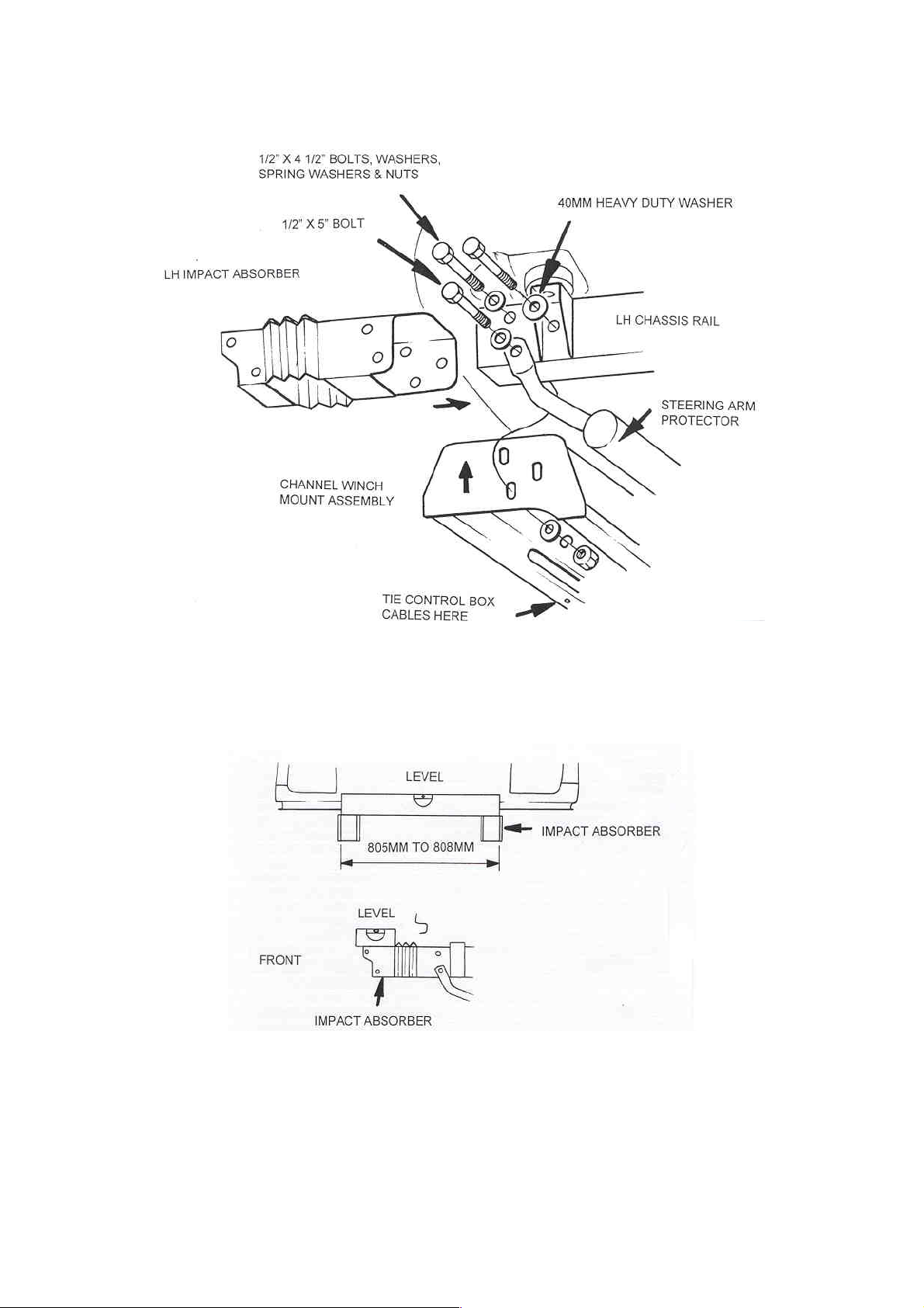
9. Slide the two Impact Absorbers over the chassis rails making sure the LH “Impact Absorber” is fitted to the LH
side and the RH “Impact Absorber” is fitted to the RH side. Lift the winch mount cradle (for winch bars only)
into position and loosely bolt in place using the 1/2” x 4 1/2” bolts, flat washers, spring washers and nuts in the
top and rear chassis holes (the 40mm heavy duty washer must be located on the outside of the rear most hole) and
the 1/2” x 5” bolt, flat washers, spring washer and nut in the lower forward chassis hole, passing through the
steering arm protector. Refer to diagram 3. (The steering arm protector is not fitted to USA models). NOTE: Due
Page 5
25-9-98 Page 5 of 6 3782513
to chassis rail width variations packers (numbers: 5846273 & 5846274), with fitting tabs, may need to be inserted
between the “Impact Absorbers” and chassis rails.
DIAGRAM 3
10. Using a level and a tape measure, adjust both Impact Absorbers so that they are parallel to each other, horizontal,
and have an overall width of between 805mm and 808mm, then tighten the bolts. Refer to diagram 4.
11. WINCH BARS ONLY:
Page 6
25-9-98 Page 6 of 6 3782513
A) Lift the winch into place and using the washers supplied in the fitting kit (3/8” for 8 or 9,000lb and 7/16” for
10,000lb) and the bolts and spring washers supplied with the winch, bolt securely into position. NOTE: The
gearbox is on the LHS for the 8 & 9,000 winches and on the RHS for the 10,000lb winch. The winch cable
spools from the bottom for all three winches.
B) Wire the winch in accordance with the Warn fitting instructions, taking care not to route the cables over sharp
edges. Tie the cables from the control box to the channel winch mount assembly using the cable tie supplied.
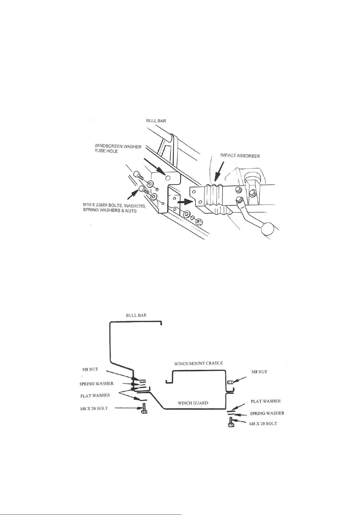
12. Lift the bull bar into place and loosely bolt to the two Impact Absorbers using the M10 x 25mm bolts, (4 per side)
washers, spring washers and nuts. Refer to diagram 5.
DIAGRAM 5
13. Adjust the bull bar until a uniform gap is achieved to the mud guards and grill. Securely tighten all bolts.
14. Connect the windscreen washer tube to the T piece and tighten the clamp.
15. FOR WINCH BARS ONLY: Fit the winch guard (optional for 8 or 9,000lb Winch) to the bull bar and winch
cradle using the M8 x 20mm bolts, flat washers, spring washers and nuts. Align the guard with the bull bar then
tighten the bolts.
DIAGRAM 6
16. Connect the bull bar turn signal indicator looms to the existing turn signal indicator loom with the Scotchloks
supplied and test to ensure they function correctly.
 Loading...