

Page 1
06-01-2005
Page 1 of 7
3782877
If you have any queries regarding the installation of this product please contact the distributor from whom it was purchased, or alternatively the ARB office in your state.
Head Office – ARB Corporation Ltd VIC: 42-44 Garden Street, Kilsyth, Victoria, 3137 Tel: (03) 9761 6622 Fax: (03) 9761 6807
WA: (08) 9244 3553 NSW: (02) 9821 3633 ACT: (02) 6280 7475 SA: (08) 8244 5001 QLD: (07) 3872 3872 NT: (08) 8947 2262 TAS: (03) 6331 4190
FRONTERA 2000 ON AIR BAG COMPATIBLE COMBINATION BAR
RODE0 / AMIGO 2000 ON (USA)
PRODUCT NUMBER FITTING KIT NUMBER
3448200 6171398
WARNING
FOR VEHICLES EQUIPPED WITH SRS AIRBAG
WHEN INSTALLED IN ACCORDANCE WITH THESE INSTRUCTIONS, THE FRONT
PROTECTION BAR DOES NOT AFFECT OPERATION OF THE SRS AIRBAG.
TAKE NOTE OF THE FOLLOWING:
• THIS PRODUCT MUST BE INSTALLED EXACTLY AS PER THESE INSTRUCTIONS
USING ONLY THE HARDWARE SUPPLIED.
• IN THE EVENT OF DAMAGE TO ANY BULL BAR COMPONENT, CONTACT YOUR
NEAREST AUTHORISED ARB STOCKIST. REPAIRS OR MODIFICATIONS TO THE
IMPACT ABSORPTION SYSTEM MUST NOT BE ATTEMPED.
• DO NOT USE THIS PRODUCT FOR ANY VEHICLE MAKE OR MODEL, OTHER THAN
THOSE SPECIFIED BY ARB.
• DO NOT REMOVE LABELS FROM THIS BULL BAR.
• THIS PRODUCT OR ITS FIXING MUST NOT BE MODIFIED IN ANY WAY.
Page 2
06-01-2005
Page 2 of 7
3782877
USE
PART No
QTY
DESCRIPTION
CHASSIS BRACKETS
6151232
4
BOLT M10 x 1.5 x 30mm
TO CHASSIS RAILS
4581048
4
WASHER SPRING M10
4581040
8
WASHER FLAT M10
6151026
4
NUT M10 x 1.5mm
3756224L
1
CHASSIS BRACKET ASSY
3756224R
1
CHASSIS BRACKET ASSY
SPLASH PAN
6151021
2
BOLT M8 x 20mm
TO BULL BAR
4581044
2
WASHER FLAT M8
3314413
1
SPLASH PAN
6151132
2
NUT FLANGE
BULL BAR TO
6151045
6
BOLT M10 x 25mm
CHASSIS BRACKETS
4581048
6
WASHER SPRING M10
4581040
6
WASHER FLAT M10
CONTROL BOX BRACKET
6151021
2
BOLT M8 x 20mm
4581044
2
WASHER FLAT M8
6151132
2
NUT FLANGE M8
3751564
1
BRACKET CONTROL BOX
NUMBER PLATE BRACKET
6151017
4
BOLT M6 x 16mm
6151035
4
WASHER FLAT M6
6151128
4
NUT FLANGE M6
3751313
1
NUMBER PLATE BRACKET
BUFFERS AND TURN SIGNALS
3500170
1
BUFFERS KIT
3500080
1
ARB TURN SIGNALS
8-9000lb WINCH TO PAN
4581040
4
WASHER FLAT 3/8”x 1”
180302
6
CABLE TIES
TOOLS REQUIRED
1 BASIC TOOL KIT, DRILL.
Page 3
06-01-2005
Page 3 of 7
3782877
ASSEMBLY SEQUENCE FOR BULL BAR INSTALLATION.
1. Remove bumper bar from the vehicle.
2. Fit the indicators into bar.
3. Fit numberplate bracket to bull bar using 6mm
hardware if bar is going to have a winch fitted.
4. Fit buffers to bull bar using 6mm flange nuts
supplied in buffer kit.
NOTE: DO NOT OVER-TIGHTEN.
If fitting XP 9.5 winch, continue to step 5,
otherwise, jump to step 12.
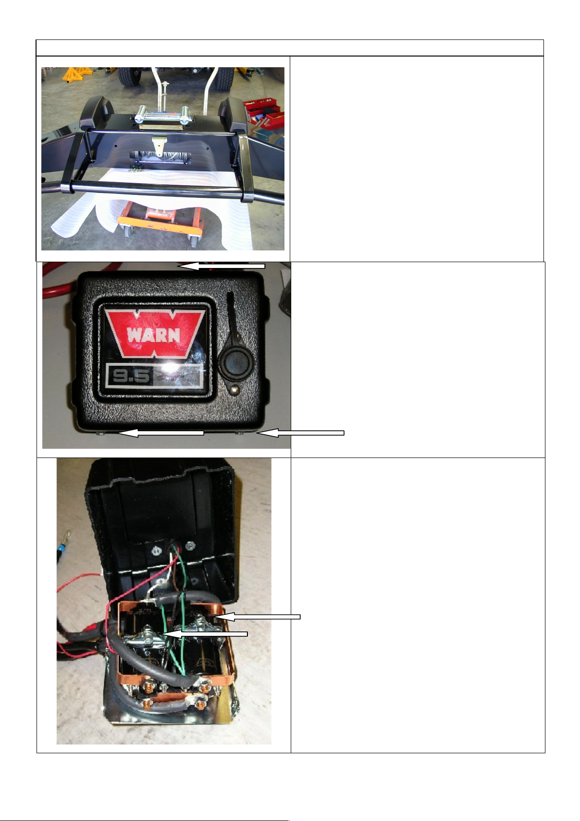
5. If fitting the XP 9.5 winch, remove the cover from
the control box.
6. Remove the two cap screws, nuts and spacer
washers that hold the four solenoids in place.
Page 4
06-01-2005
Page 4 of 7
3782877
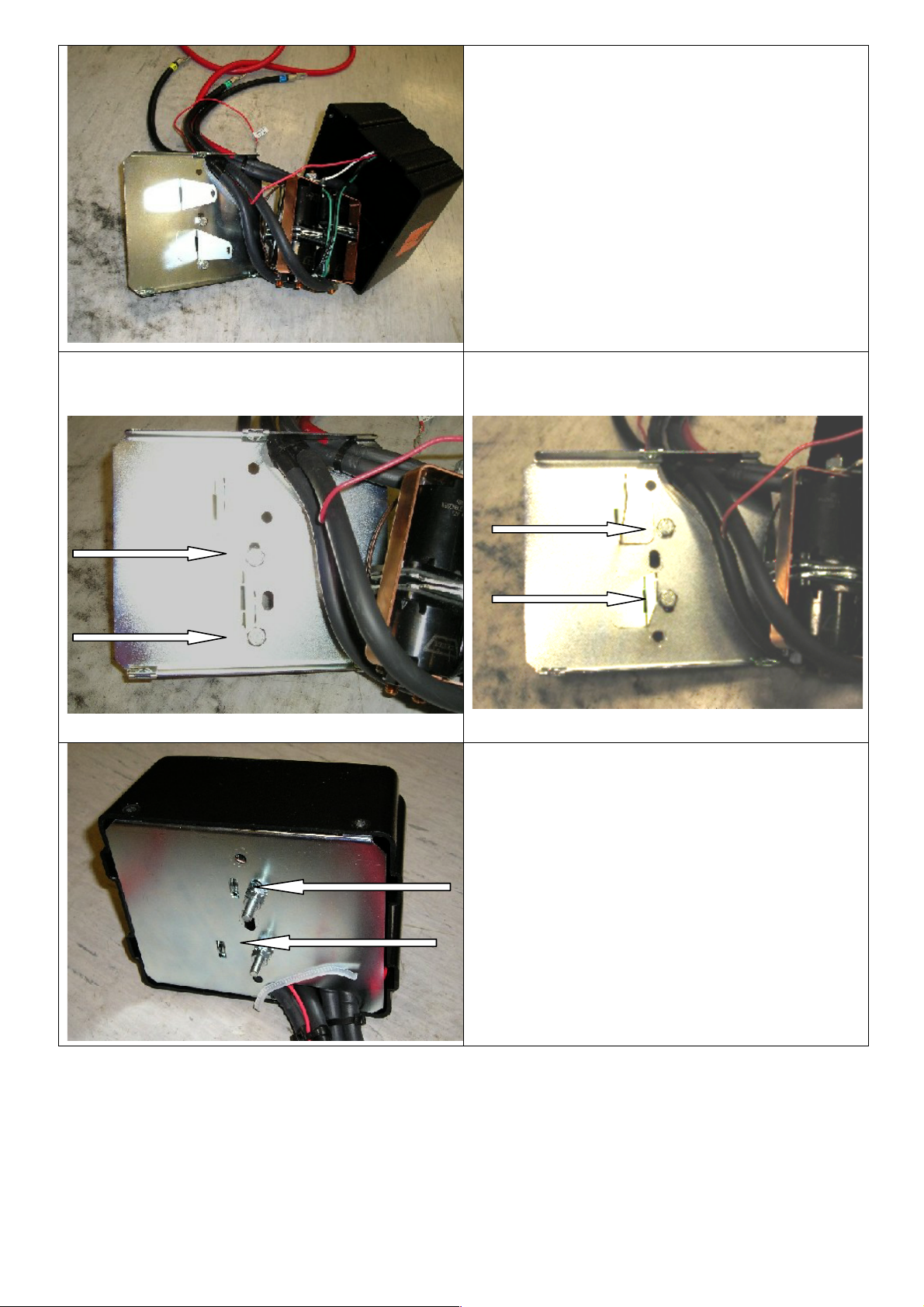
7. Remove the four solenoids from the base of the
control box using the copper bus bar as an aid
and hold to one side.
Before
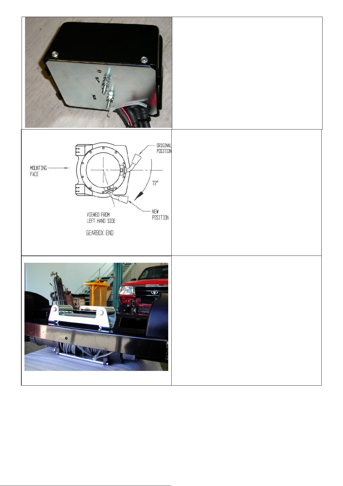
8. Remove the two bolts in the base of the control
box and reposition them into the more
centralised holes.
After
9. Place the 4 solenoids over the 2 metal stands
that are facing upwards. Make sure they line up
with the holes in the base.
Page 5
06-01-2005
Page 5 of 7
3782877
10. Replace the 2 cap screws, washers and nuts
removed in step 6 above into original holes.
11. Replace the black cover and refit the three
cover screws (DO NOT OVER TIGHTEN)
12. Fit control box bracket to bull bar using 8mm
hardware.
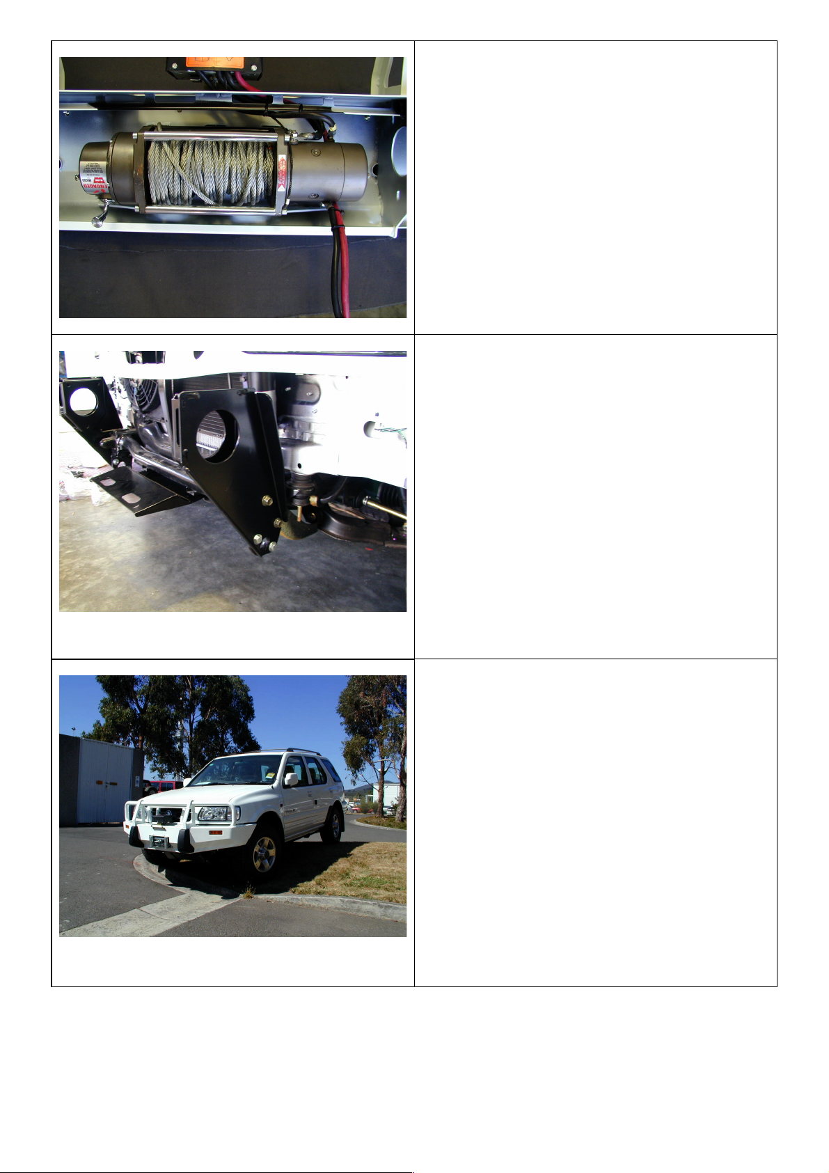
13. To place the clutch handle in the correct
position, the winch gearbox must be rotated 72
degrees (2 hole spacings), in clockwise
direction when viewed from gearbox end. Place
the winch on its end and remove all gearbox
bolts. Gently raise the gearbox just enough to
rotate it. When the correct position is located,
refit all bolts and tighten.
NOTE: Take care not to lift the assembly more
than a couple of millimeters while rotating to
correct position to avoid unmeshing the gears.
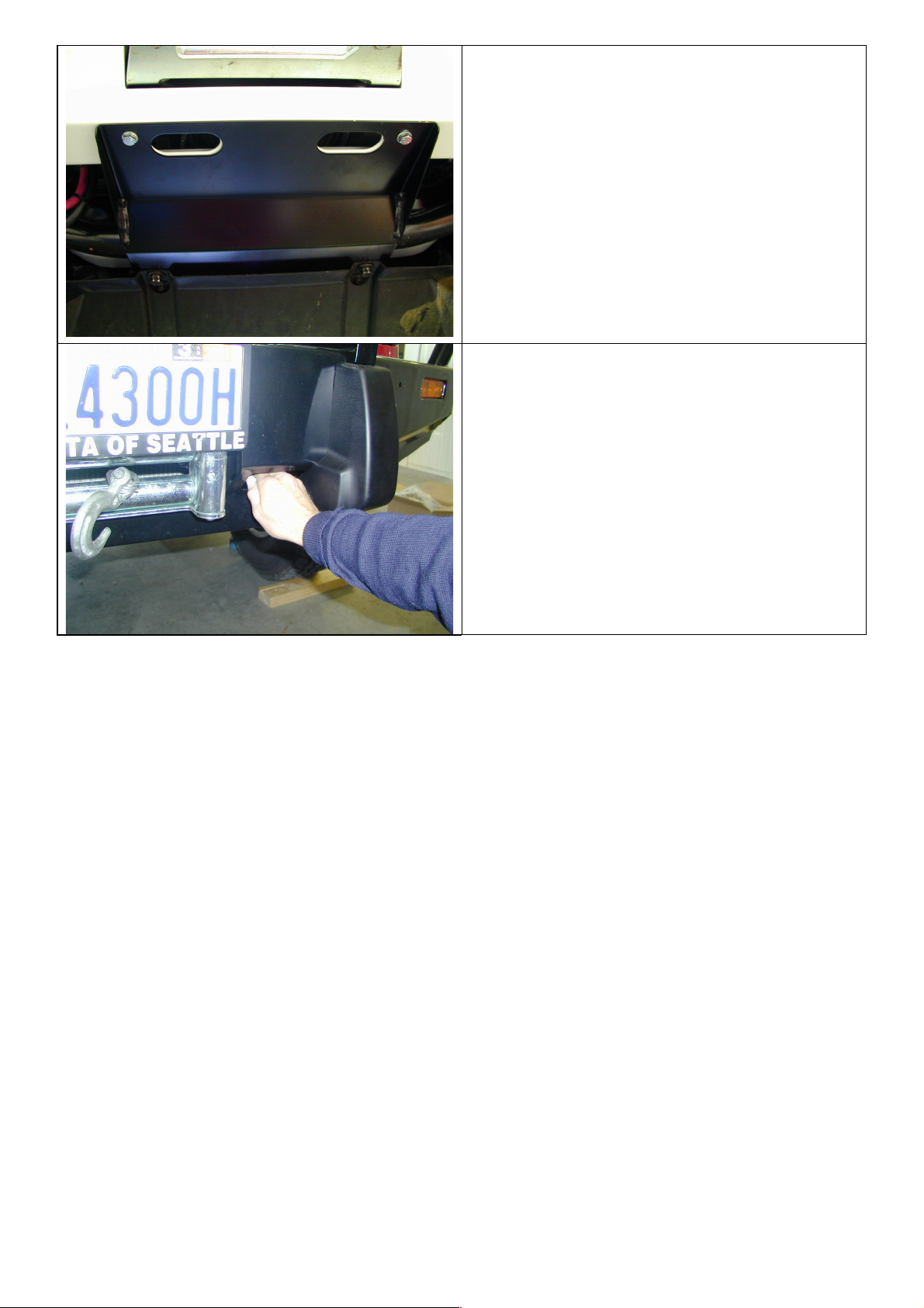
14. Once winch is rotated, positioned winch on
bench face up.
15. Lower bull bar on top of winch and align holes
with each other.
16. Place roller fairlead in bar cutout over lower
holes and fasten using 3/8” Warn hardware and
4 3/8” flat washers supplied in bolt kit.
17. When all is positioned, tighten all bolts firmly.
Page 6
06-01-2005
Page 6 of 7
3782877
18. Fit control box to control box bracket and
tighten firmly.
19. Pull wires through viewer cutout under control
box and wire up as per Warn instruction
manual.
20. Tie back cables clear of all moving parts with
cable tie supplied.
21. Place ground earth lead under bolt of winch
tension bar.
22. Fit chassis brackets to both sides of the vehicle
using original 12mm bolts.
23. Fit 10mm x 30mm bolts to lower holes and
fasten using 10mm hardware.
24. When all bolts are fitted, tighten firmly.
25. Lift bar into position between chassis brackets
and bolt up using M10 x 25mm bolts, spring
and flat washers. Finger tighten only. (Bolts fit
from inside of bar.)
26. Adjust bar so that there is a 20mm gap around
the periphery of the vehicle and securely tighten
all remaining bolts throughout.
27. Wire main power leads to battery as per Warn
instructions and cable tie leads securely from all
moving parts with cable ties supplied.
28. Fit number plate to number plate bracket
(winch) or fit number plate to lower holes in
bar face to cover roller fairlead cutout (non
winch) using 6mm hardware.
29. Pull winch cable through roller fairlead, and fit
tow hook.
Page 7
06-01-2005
Page 7 of 7
3782877
30. Connect the turn signal looms to the existing
turn signal loom with the Scotchloks supplied.
Test to ensure the turn signals function
correctly.
31. Once bar is correctly fitted, undo front bolts in
splash pan of vehicle, slide splash pan supplied
between and refit bolts and finger tighten.
32. Using 8mm hardware supplied, bolt splash pan
to front of underside of bar. When all bolts are
fitted, tighten firmly.
33. If driving lights are to be fitted, use extension
bar with ratchet, ¾” long reach socket to tighten
from cutout in bottom of center pan.
34. Winch handle is operated from underneath bull
bar from left-hand side of vehicle.
 Loading...