

Page 1
Part Number: 3410100
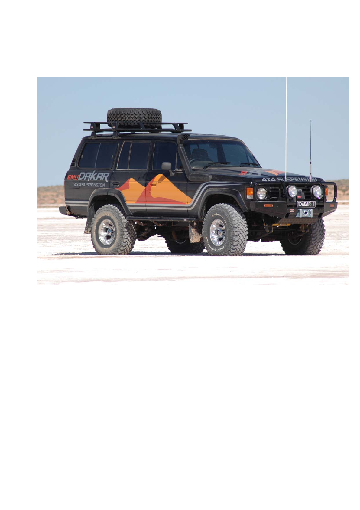
Description: ARB “DAKAR” WINCH BAR TO SUIT TOYOTA LAND CRUISER
60 SERIES
WARNING
♦ When installed in accordance with these instructions, the front protection bar does not
affect operation of the SRS airbag.
♦ This product must be installed exactly as per these instructions using only the hardware
supplied.
♦ In the event of damage to any bull bar component, contact you’re nearest authorised ARB
stockist. Repairs or modifications to the impact absorption system must not be attempted.
♦ Do not use this product for any vehicle make or model, other than those specified by ARB.
♦ Do not remove labels from this bull bar.
♦ This product or its fixing must not be modified in any way.
♦ The installation of this product may require the use of specialized tools and/or techniques
♦ It is recommended that this product is only installed by trained personnel
♦ These instructions are correct as at the publication date. ARB Corporation Ltd. cannot be
held responsible for the impact of any changes subsequently made by the vehicle
manufacturer
♦ During installation, it is the duty of the installer to check correct operation/clearances of all
components
♦ Work safely at all times
♦ Unless otherwise instructed, tighten fasteners to specified torque
www.arb.com.au
Corporate Head Office
42-44 Garden St Tel: +61 (3) 9761 6622
Kilsyth, Victoria Fax: +61 (3) 9761 6807
AUSTRALIA 3137
Last Rev Date: 26/05/2006 Page 1 of 9 Fitting instructions# 3783204
Copyright © 2005 by ARB Corporation Limited. All rights reserved, this document must not be reproduced without the express authority of ARB Corporation Ltd
Page 2
FITTING REQUIREMENTS
REQUIRED TOOLS FOR FITMENT OF PRODUCT:
Basic tool kit Drill and 10mm drill bit
Test lamp
HAVE AVAILABLE THESE SAFETY ITEMS WHEN FITTING PRODUCT:
Protective eyewear
Hearing protection
NOTE: ‘WARNING’ notes in the fitting procedure relate to OHS situations, where to avoid a
potentially hazardous situation it is suggested that protective safety gear be worn or a safe work
procedure be employed. If these notes and warnings are not heeded, injury may result.
Last Rev Date: 26/05/2006 Page 2 of 9 Fitting instructions# 3783204
Copyright © 2005 by ARB Corporation Limited. All rights reserved, this document must not be reproduced without the express authority of ARB Corporation Ltd
Page 3
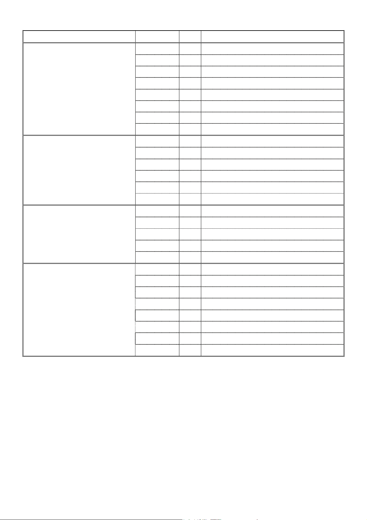
WHERE USED PART No QTY DESCRIPTION
CHASSIS BRACKETS TO
CHASSIS
BULL BAR TO CHASSIS
BRACKETS
NUMBER PLATE AND
INDICATORS TO BAR
3756862L 1 Chassis bracket assembly LHS
3756862R 1 Chassis bracket assembly RHS
5846279 4 Spacer chassis 32 x 14 x 24mm
6151100 8 Bolt ½” x 1 ½” hex head
6151101 4 Bolt ½” x 2” hex head
4581049 24 Washer flat ½”
4581050 12 Washer spring ½”
6151138 12 Nut ½” hex
6151100 4 Bolt ½” x 1 ½” hex head
4581049 8 Washer flat ½”
4581050 4 Washer spring ½”
6151232 2 Bolt M10 x 1.5 x 30mm
4581040 4 Washer flat M10
4581048 2 Washer spring M10
3751451 1 Bracket number plate
6151017 4 Bolt M6 x 16mm
6151046 4 Washer flat M6
6151128 4 Nut flange M6
WINCH AND CONTROL BOX
TO BAR
3500080 1 Universal indicator kit
3756209 1 Bracket winch control box
6151021 2 Bolt M8 x 20mm
4581044 2 Washer flat M8
6151132 2 Nut flange M8
6151074 2 Bolt 3/8” x 1 ¾” hex head
6151073 2 Bolt 3/8” x 1 ½” hex head
4581040 4 Washer flat M10
4581048 4 Washer spring M10
Last Rev Date: 26/05/2006 Page 3 of 9 Fitting instructions# 3783204
Copyright © 2005 by ARB Corporation Limited. All rights reserved, this document must not be reproduced without the express authority of ARB Corporation Ltd
Page 4
FITTING PROCEDURE
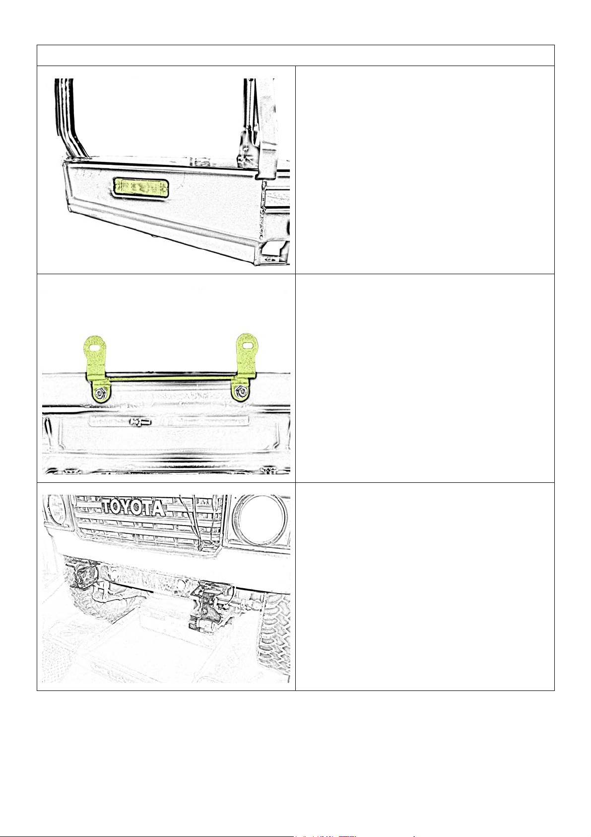
1. Place the bull bar on a suitable surface
or stand and fit the indicators using the
hardware provided in the indicator kit.
2. Fit the licence plate bracket to the bull
bar using two M6 x 16mm bolts, M6 flat
washers and M6 flange nuts.
3. Remove the existing bumper bar or bull
bar from the vehicle.
Last Rev Date: 26/05/2006 Page 4 of 9 Fitting instructions# 3783204
Copyright © 2005 by ARB Corporation Limited. All rights reserved, this document must not be reproduced without the express authority of ARB Corporation Ltd
Page 5
FITTING PROCEDURE
New
position
Old
position
NOTE: IF NOT FITTING A WINCH PROCEED
TO STEP 11
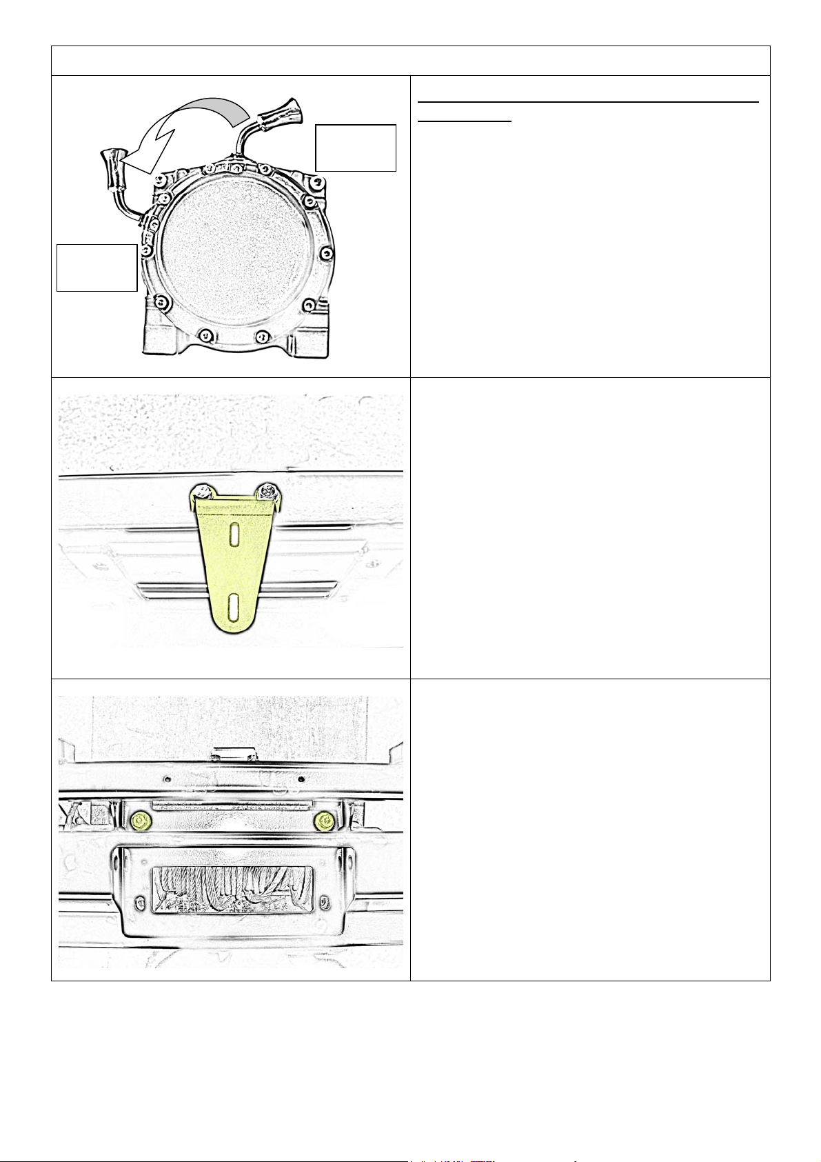
3. For low mount winches below 10000lb
capacity, remove the ten cap screws
from the gearbox and carefully lift and
rotate the gearbox 72 degrees counter
clockwise. (two hole spaces) Re-insert
and tighten the cap screws.
Note: For high mount winches go to step 5.
4. When fitting a low mount winch, fit the
control box bracket to the bar. Fit using
two M8 x 20mm bolts, M8 flat washers
and M8 flange nuts.
5. Lay the winch on a bench or stand with
the legs facing upwards. With the help
of an assistant, carefully place the bull
bar over the top of the winch so that the
holes line up with the winch mounting
holes.
6. Fit the winch to the bar with two 3/8” x 1
½” bolts with M10 flat washers and M10
spring washers to the two top holes.
Last Rev Date: 26/05/2006 Page 5 of 9 Fitting instructions# 3783204
Copyright © 2005 by ARB Corporation Limited. All rights reserved, this document must not be reproduced without the express authority of ARB Corporation Ltd
Page 6
FITTING PROCEDURE
Drill the new
hole 20mm
below original
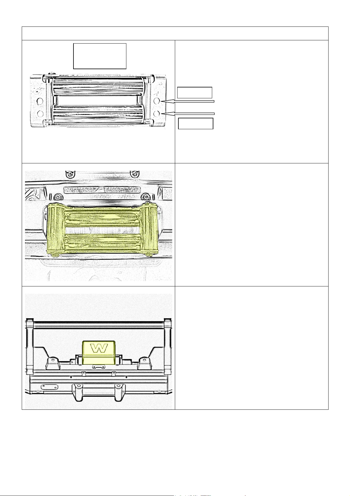
7. Using a 12mm drill bit, drill two new
holes in the roller fairlead 20mm below
the original holes.
Original
New hole
8. Fit the roller fairlead to the bar using
two 3/8” x 1 ¾” bolts, M10 flat and
spring washers. Tighten all winch bolts.
9. Fit the control box to the control box
bracket using the nuts and washers that
came with the winch kit.
10. Wire the control box to the winch
according to the instructions provided
with the winch.
Last Rev Date: 26/05/2006 Page 6 of 9 Fitting instructions# 3783204
Copyright © 2005 by ARB Corporation Limited. All rights reserved, this document must not be reproduced without the express authority of ARB Corporation Ltd
Page 7
FITTING PROCEDURE
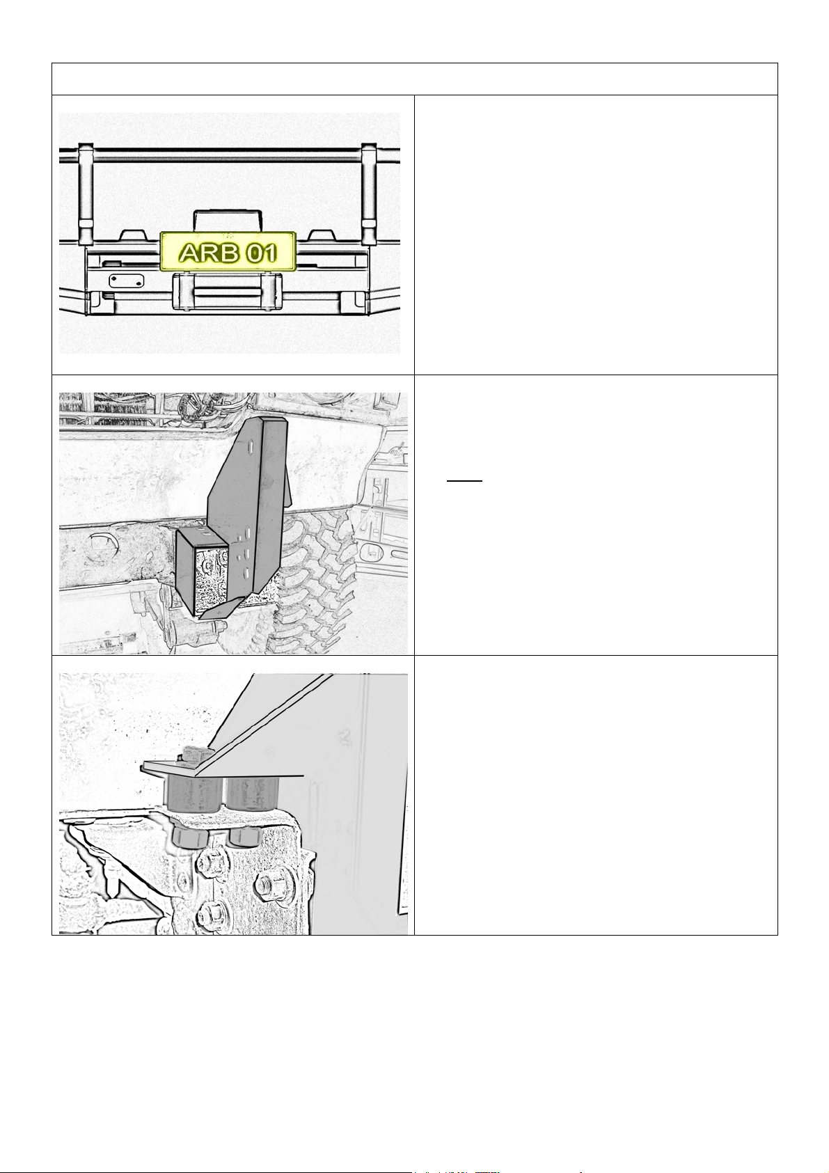
11. Fit the licence plate to the bull bar using
two M6 x 16mm bolts, M6 flat washers
and M6 flange nuts.
12. Fit the left and right hand bull bar
mounting brackets to the appropriate
chassis rails.
Note
: Due to the age of the vehicles the
use of a hammer may be necessary, if so
use a piece wood against the part. Do not
hit the part directly with the hammer.
13. If necessary use the 25mm spacers
provided in the fitting kit between the
mounting bracket and the out riggers of
the chassis. Fix in place with ½” x 2”
bolts, ½” flat washers, ½” spring
washers and ½” nuts. Do not tighten.
Last Rev Date: 26/05/2006 Page 7 of 9 Fitting instructions# 3783204
Copyright © 2005 by ARB Corporation Limited. All rights reserved, this document must not be reproduced without the express authority of ARB Corporation Ltd
Page 8
FITTING PROCEDURE
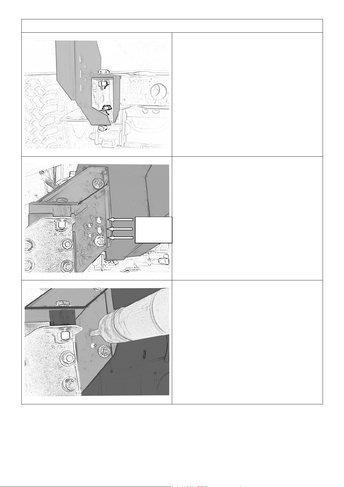
14. Fix the mounting bracket to the chassis
using four ½” x 1 ½” bolts, eight ½” flat
washers, four ½” spring washers and
four ½” nuts. When happy with the
alignment of the brackets tighten all the
bolts.
15. With the help of an assistant, lift the bar
onto the mounting brackets. Align the
holes in the bull bar with the holes in the
mounting bracket to the desired height.
(see diagram opposite)
16. Fix the bull bar in place using two ½” x 1
2” lift
1” lift
STD
½” bolts, four ½” flat washers, two ½”
spring washers and two ½” nuts for
each side.
17. Using the hole in the mounting bracket
as a guide, drill a 10mm hole through
the bull bar upright for the pinning bolt.
18. Pin the bar using a M10 x 30mm bolt,
two M10 flat washers, M10 spring
washer and M10 nut. Tighten the bolt.
Repeat for the other side.
Note: There are two holes provided for
pinning depending on what height the bull
bar has been set at.
Last Rev Date: 26/05/2006 Page 8 of 9 Fitting instructions# 3783204
Copyright © 2005 by ARB Corporation Limited. All rights reserved, this document must not be reproduced without the express authority of ARB Corporation Ltd
Page 9
19. With the bull bar fitted and all bolt tightened, wire the indicators and winch. (if fitted) Use a
test lamp to find the correct wires for the indicators to tap into and use the scotch locks
provided to join the wires together. Refer to the winch fitting instructions for correct wiring
of the winch. Make sure all wiring is clear of hot, moving or sharp objects.
Last Rev Date: 26/05/2006 Page 9 of 9 Fitting instructions# 3783204
Copyright © 2005 by ARB Corporation Limited. All rights reserved, this document must not be reproduced without the express authority of ARB Corporation Ltd
 Loading...