

Page 1
02-08-12 Page 1 of 22 3787827
If you have any queries regarding the installation of this product please contact the distributor from whom it was purchased, or alternatively the ARB office in your state.
Head Office – ARB Corporation Ltd VIC: 42-44 Garden Street, Kilsyth, Victoria, 3137 Tel: (03) 9761 6622 Fax: (03) 9761 6807
WA:(08) 9244 3553 NSW: (02) 9821 3633 ACT: (02) 6280 7475 SA: (08) 8244 5001 QLD: (07) 3872 3872 NT: (08) 8947 2262 TAS: (03) 6331 4190
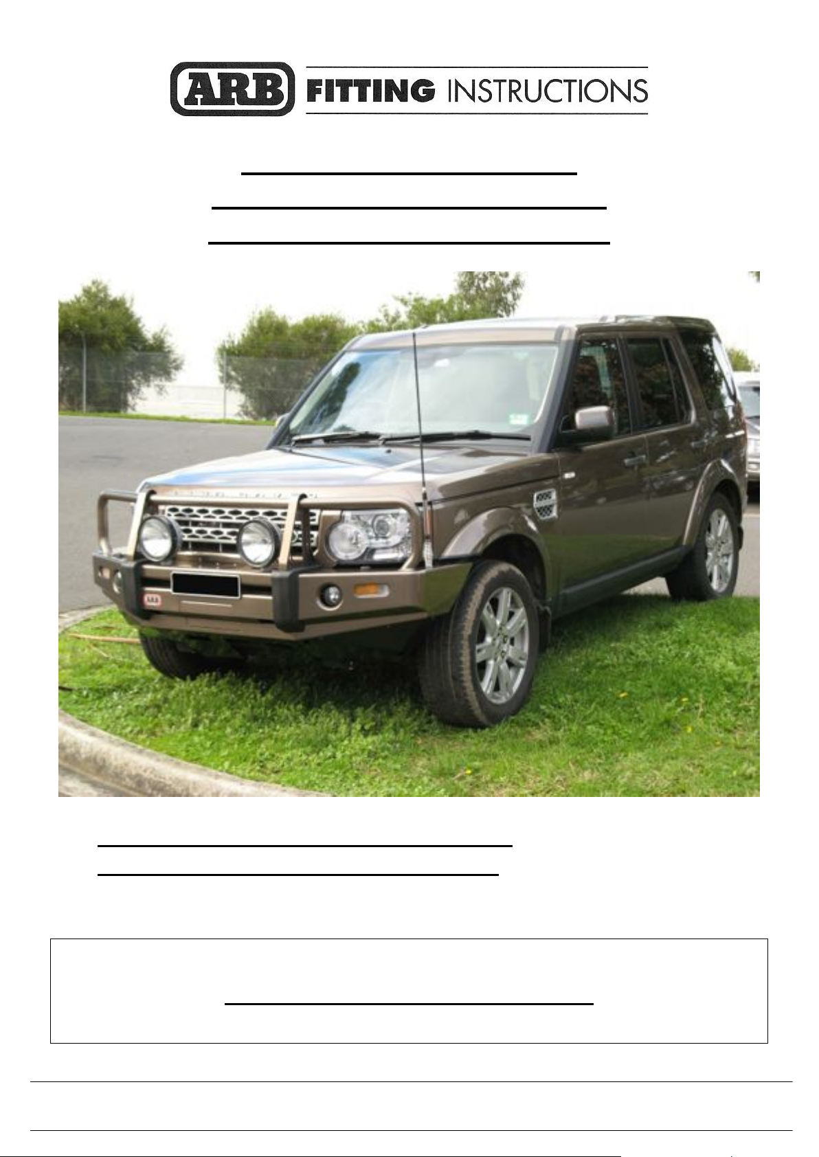
LAND ROVER DISCOVERY 4
ARB BULL BAR AND WINCH BAR
Not suitable for HSE & V8 models.
PART No 3432200 DISCOVERY 4 WINCH BAR
PART No 3232200 DISCOVERY 4 BULL BAR
WARNING
FOR VEHICLES EQUIPPED WITH SRS AIRBAG
WHEN INSTALLED IN ACCORDANCE WITH THESE INSTRUCTIONS, THE FRONT
PROTECTION BAR DOES NOT AFFECT OPERATION OF THE SRS AIRBAG.
Page 2

02-08-12 Page 2 of 22 3782929
TAKE NOTE OF THE FOLLOWING:
THIS PRODUCT MUST BE INSTALLED EXACTLY AS PER THESE INSTRUCTIONS
USING ONLY THE HARDWARE SUPPLIED.
IN THE EVENT OF DAMAGE TO ANY BULL BAR COMPONENT, CONTACT YOUR
NEAREST AUTHORISED ARB STOCKIST. REPAIRS OR MODIFICATIONS TO THE
IMPACT ABSORPTION SYSTEM MUST NOT BE ATTEMPTED.
DO NOT USE THIS PRODUCT FOR ANY VEHICLE MAKE OR MODEL, OTHER THAN
THOSE SPECIFIED BY ARB.
DO NOT REMOVE LABELS FROM THIS BULL BAR.
THIS PRODUCT OR ITS FIXING MUST NOT BE MODIFIED IN ANY WAY.
Corporate Head Office
42-44 Garden St Tel: +61 (3) 9761 6622
Kilsyth, Victoria Fax: +61 (3) 9761 6807
AUSTRALIA 3137
Australian enquiries [email protected]
North & South American enquiries [email protected]
Other international enquiries [email protected]
www.arb.com.au
GENERAL CARE AND MAINTENANCE
By choosing an ARB set of side rails, you have bought a product that is one of the most sought after 4WD
products in the world. Your side rails are a properly engineered, reliable, quality accessory that represents
excellent value. To keep your side rails in original condition it is important to care and maintain it
following these recommendations:
Prior to exposure to the weather your bar should be treated to a Canuba based polish on all exposed
surfaces. It is recommended that this is performed on a six monthly basis or following exposure to salt,
mud, sand or other contaminants.
As part of any Pre Trip Preparation, or on an annual basis, it is recommended that a thorough visual
inspection of the side rails and bull bar is carried out, making sure that all bolts and other components
are torqued to the correct specification. Also check that all wiring sheaths, connectors, and fittings are
free of damage. Replace any components as necessary. This service can be performed by your local
authorized ARB Stockist.
Page 3
02-08-12 Page 3 of 22 3782929
FITTING REQUIREMENTS
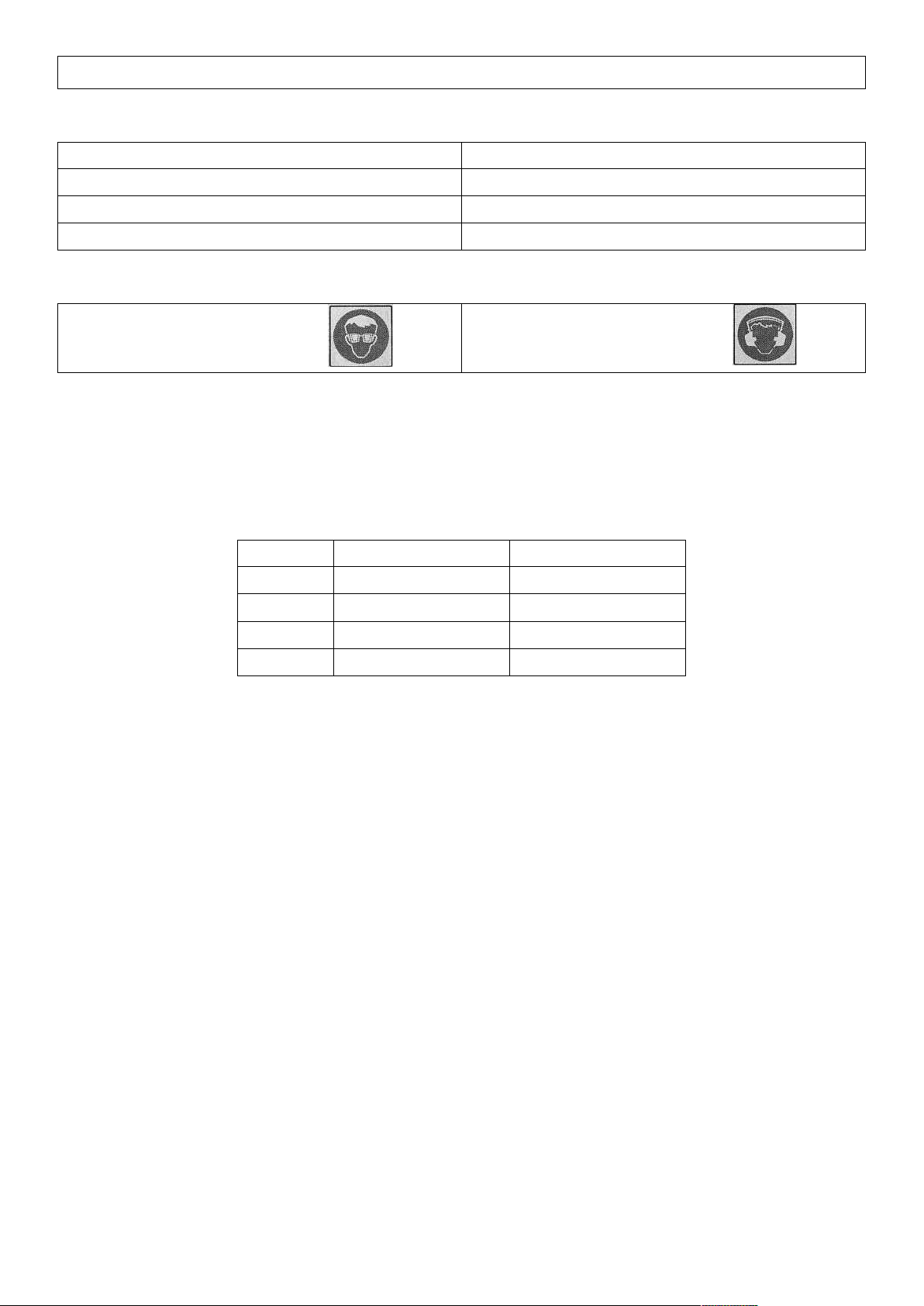
REQUIRED TOOLS FOR FITMENT OF PRODUCT:
POWER DRILL WITH 8 & 10MM BITS
SCREWDRIVER SET
METRIC SOCKET SET & SPANNERS
KEY HOLE SAW
TORX BIT SET
SHARP KNIFE & WHITE MARKER
SENSOR SAFE SILICONE
HAVE AVAILABLE THESE SAFETY ITEMS WHEN FITTING PRODUCT:
Protective eyewear
Hearing protection
NOTE:‘WARNING’notesinthefittingprocedurerelatetoOHSsituations,wheretoavoidapotentially
hazardous situation it is suggested that protective safety gear be worn or a safe work procedure be
employed. If these notes and warnings are not heeded, injury may result.
FASTENER TORQUE SETTINGS:
SIZE
Torque Nm
Torque lbft
M6
9Nm
7lbft
M8
22Nm
16lbft
M10
44Nm
32lbft
M12
77Nm
57lbft
Page 4
02-08-12 Page 4 of 23 3787827
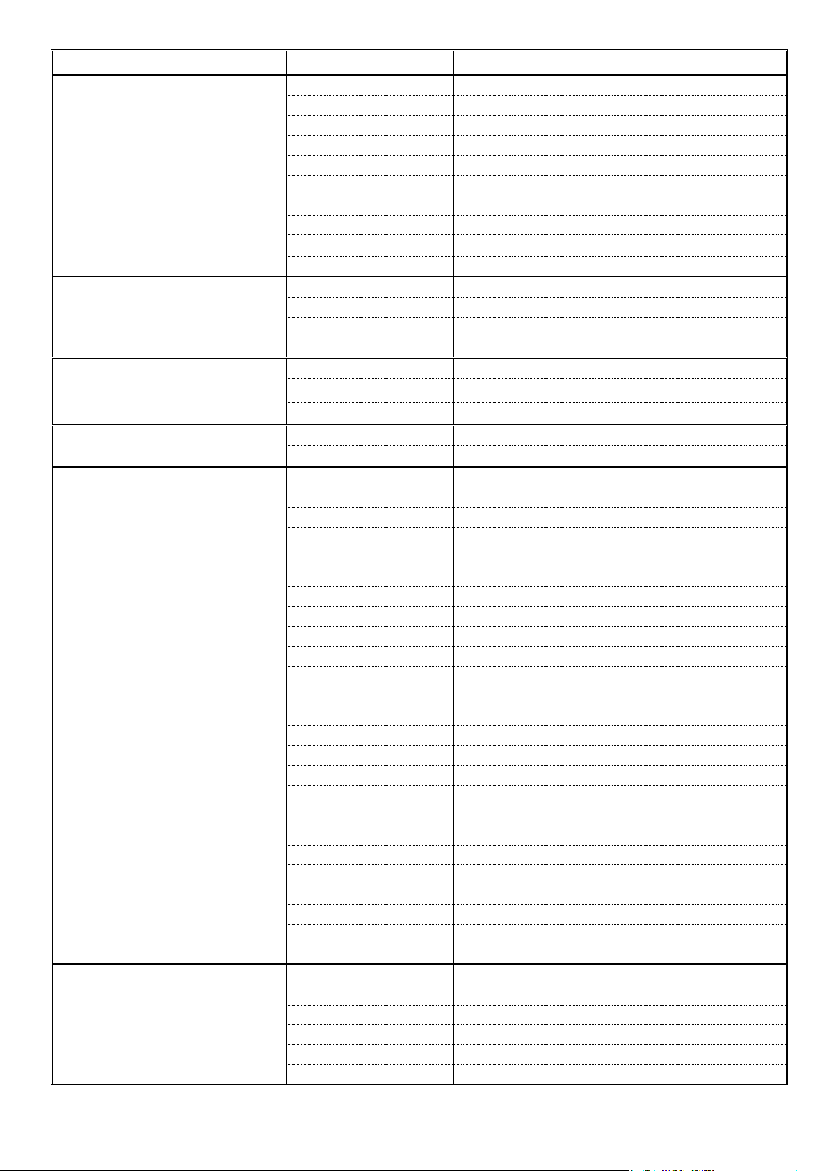
USE
PART no
QTY
DESCRIPTION
IMPACT ABSORBER TO
CHASSIS
3758047L
1
CHASSIS MOUNT BRACKET ASSEMBLY
3758047R
1
CHASSIS MOUNT BRACKET ASSEMBLY
6151204
4
BOLT M10 x 35 x 1.5p HEX HEAD
6151321
4
NUT FLANGE M10 x 1.5
4581040
4
WASHER FLAT M10
4581048
4
WASHER SPRING M10
6151022
8
BOLT M8 x 25mm HEX HEAD
4581044
8
WASHER FLAT M8
4581046
8
WASHER SPRING M8
CR08
1
SPIRAL WRAP
BULL BAR TO IMPACT
ABSORBER
6151204
8
BOLT M10 x 35 x 1.5p HEX HEAD
6151321
8
NUT FLANGE M10 x 1.5
4581040
8
WASHER FLAT M10
4581048
8
WASHER SPRING M10
BUFFERS TO BULL BAR
3162470L
1
BUFFER 260 x 230 STANDARD
3162470R
1
BUFFER 260 x 230 STANDARD
6151128
12
NUT FLANGE M6
LICENCE PLATE TO BULL
BAR
6821116
2
NYLON PLUG
6151143
2
SCREW TEK 8-18 x 20mm
FOG LIGHTS, INDICATORS
AND SENSORS (IF FITTED)
TO BULL BAR
6151300
4
CAGE NUT M6
6821116
4
NYLON PLUG
3758046L
1
FOG LIGHT BRACKET
3758046R
1
FOG LIGHT BRACKET
3756778L
1
COVER MOUNT BRACKET
3756778R
1
COVER MOUNT BRACKET
3758092
2
BRACKET OUTER SENSOR MOUNT
3758093
2
BRACKET INNER SENSOR MOUNT
6821151L
1
INDICATOR COMBINATION LAMP
6821151L
1
INDICATOR COMBINATION LAMP
6821152
2
COMBINATION LAMP WIRING LOOM
180701
6
SCOTCH LOCK
6151309
6
CAPTIVE U-TYPE NUT
3162468
2
FOG LIGHT INSERT
6151317
8
SCREW 8-18 x 5/8 PAN HEAD
6151213
8
BOLT M6 x 20mm BLACK ZINK
4581082
8
WASHER FLAT M6 x 20 BLACK ZINK
4581287
4
WASHER SPRING M6 BLACK ZINK
6151128
4
NUT FLANGE M6
6151308
4
SCREW 8-ABX1”PANHEAD
6151460
4
SCREW SELF TAPPING
3787854
1
DRILLING TEMPLATE OUTER
3787855
1
DRILLING TEMPLATE INNER
6821198
1
INDICATOR LOOM KIT
WINCH TO BULL BAR
(SUPPLIED WITH FITTING
KIT 6171975 ONLY)
3756499
1
CONTROL BOX MOUNT
BLB850
3
WINCH LEAD 850mm BLACK
6151074
2
BOLT3/8”x1¾”HEXHEAD
6151073
2
BOLT3/8”x1½”HEXHEAD
4581040
4
WASHER FLAT M10
4581048
4
WASHER SPRING M10
Page 5
02-08-12 Page 5 of 23 3787827
6151021
2
BOLT M8 x 20mm
6151132
2
NUT FLANGE M8
4581044
2
WASHER FLAT M8
180302
6
CABLE TIES
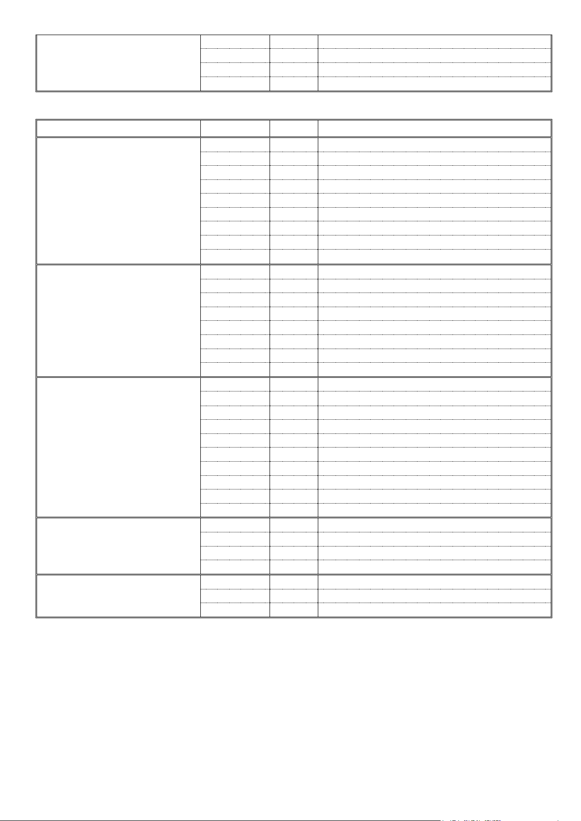
USE
PART No
QTY
DESCRIPTION
WASHER BOTTLE
SUPPORT TO IMPACT
ABSORBERS
3756801
2
WASHER BOTTLE SUPPORT BRACKET
6151301
4
CAGE NUT M8
6151021
4
BOLT M8 x 20mm HEX HEAD
4581044
4
WASHER FLAT M8
4581046
4
WASHER SPRING M8
6151300
2
CAGE NUT M6
6151213
2
BOLT M6 x 20mm BLACK ZINK
4581082
2
WASHER FLAT M6 x 20 BLACK ZINK
4581287
2
WASHER SPRING M6 BLACK ZINK
STONE TRAY & FAIRLEAD
COVER TO BULL BAR
6542109
1
STONE TRAY
3758045
1
FAIRLEAD COVER
6151357
4
BOLT M10 SEMS
6151304
4
CAGE NUT M10
6151300
4
CAGE NUT M6
6151213
6
BOLT M6 x 20mm BLACK ZINK
4581082
6
WASHER FLAT M6 x 20 BLACK ZINK
4581287
6
WASHER SPRING M6 BLACK ZINK
WASHER BOTTLE STONE
TRAYS TO BULL BAR
6542110L
1
WASHER BOTTLE TRAY
6542110R
1
WASHER BOTTLE TRAY
6151301
2
CAGE NUT M8
6151300
10
CAGE NUT M6
6151262
2
BOLT M8 x 20mm BLACK ZINK
4581045
2
WASHER FLAT M8 BLACK ZINK
4581047
2
WASHER SPRING M8 BLACK ZINK
6151213
10
BOLT M6 x 20mm BLACK ZINK
4581082
10
WASHER FLAT M6 x 20 BLACK ZINK
4581287
10
WASHER SPRING M6 BLACK ZINK
RETAINING FENDER
LINERS TO WASHER
BOTTLE TRAYS
6151300
4
CAGE NUT M6
6151213
4
BOLT M6 x 20mm BLACK ZINK
4581082
4
WASHER FLAT M6 x 20 BLACK ZINK
4581287
4
WASHER SPRING M6 BLACK ZINK
MISCELLANEOUS
180302
10
CABLE TIES
3162152
2
ARIAL PLUG
6191009
1
PLASTIC SIDE MOULDING
Page 6
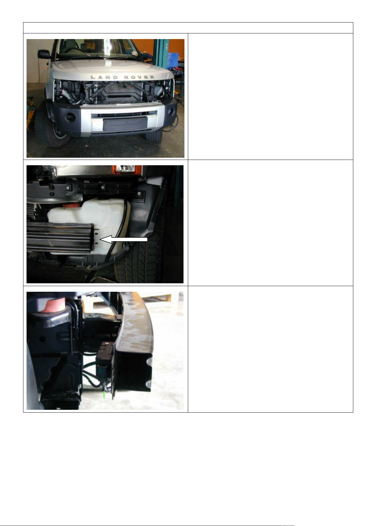
02-08-12 Page 6 of 23 3787827
VEHICLE PREPARATION
1. Remove the grill and then the headlights
from the vehicle.
2. Remove the flares from the vehicle.
3. Remove the bumper bar from the vehicle.
NOTE: Be prepared to block or clamp off
the washer bottles lines to prevent water
leaking on the ground.
4. Remove the two bolts attaching the
bumper cross bar to the washer bottle.
5. On air suspension models, remove the
solenoid pack attached to the right hand
side of the crossbar.
6. Remove the crossbar from the vehicle.
Page 7
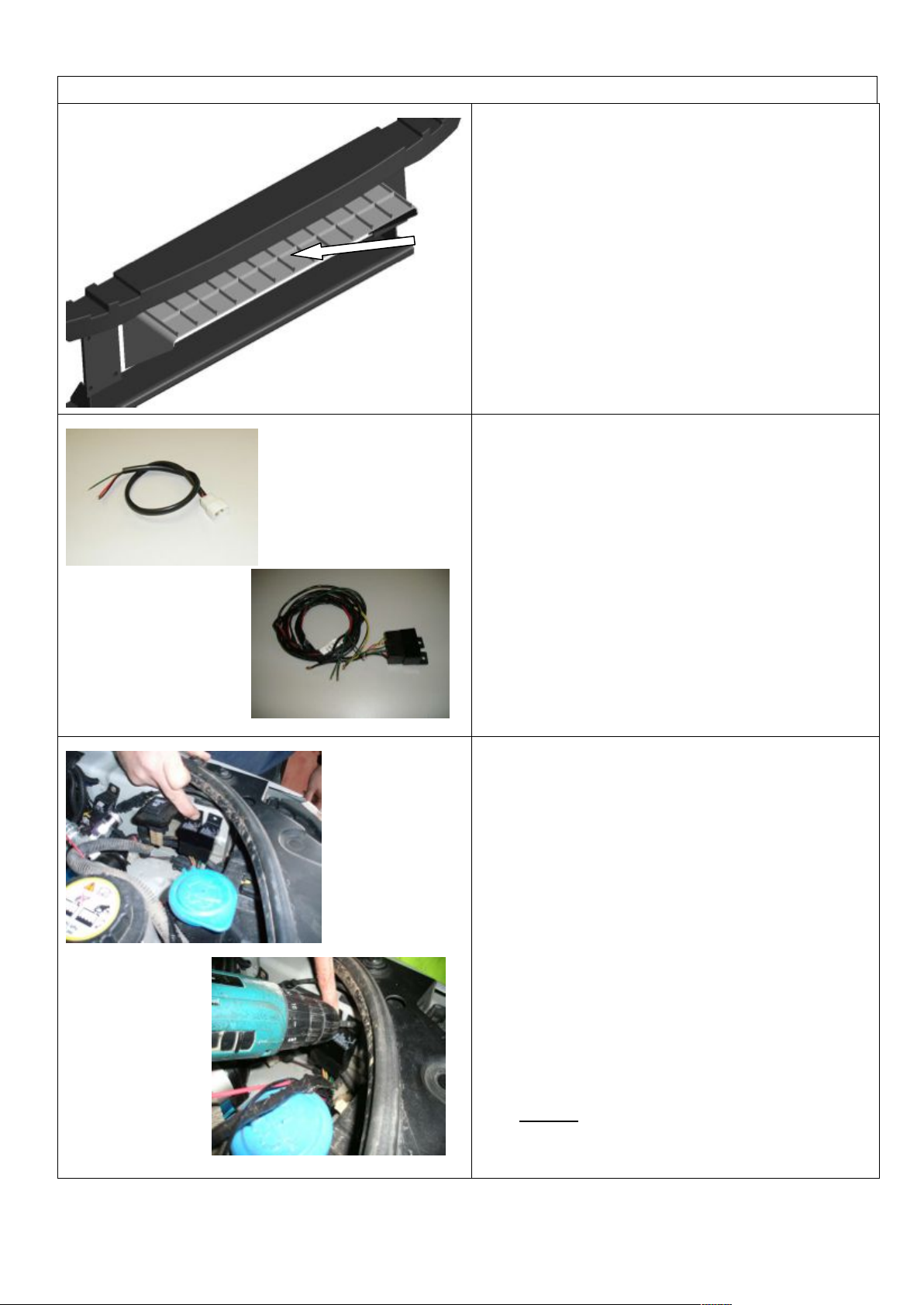
02-08-12 Page 7 of 23 3787827
VEHICLE PREPARATION
7. If fitting a winch the plastic air ram will
need to be removed.
Short loom .
Longer relay loom .
8. To wire up the indicators from the bull
bar to the vehicle indicators a short loom
must be fitted .
A longer loom with two relays is also to be
fitted in conjunction with the short turn
signal loom .
9. Open the bag containing the long wiring
loom with relays .
Lay the loom across the engine bay from
headlamp to headlamp with the relays on
the Left Hand ( battery ) side of
the vehicle .
Place the relays on the inner guard ( as
shown ) as close as possible to the
battery .
Using a drill and a Phillips head bit attach
the relays to the vehicle with the screws
provided .
Note :- Ensure wiring will not rub on
any metal part or sharp edges .
Page 8
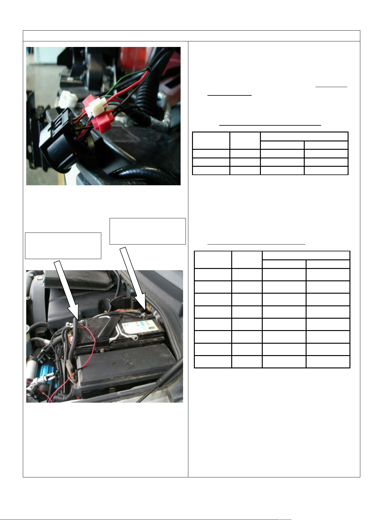
02-08-12 Page 8 of 23 3787827
VEHICLE PREPARATION
10. Find the clearance , indicator and earth
wires for each headlight using a test lamp.
Removal of the headlamp will make this
easier . Wire the park lamp wire ONLY AT
THIS STAGE from the short indicator looms
into the head light looms using the scotch
locks provided .
WIRING TABLE FOR SHORT LOOM
FUNCTION
INDICATOR
HARNESS
VEHICLE COMBINATION LAMP
RIGHT
LEFT
INDICATOR
GREEN
GREEN / WHITE
GREEN / RED
EARTH
BLACK
BLACK
BLACK
PARK LAMP
RED
RED / ORANGE
RED / BLACK
11. The remaining wires from the short loom
( tabled above ) will now in conjunction with
the longer loom - will be both wired into the
vehicles headlamp loom . The table below
lists the colour & function of the longer relay
loom .
WIRING TABLE FOR LONG LOOM
FUNCTION
RELAY
HARNESS
SHORT INDICATOR HARNESS
RIGHT
LEFT
BATTERY
POSITIVE
RED
-------
------
BATTERY
EARTH
BLACK
-------
------
VEHICLE RH
INDICATOR
GREEN /
BLACK
------
------
BULL BAR
INDICATOR
GREEN
GREEN
GREEN
BULL BAR
INDICATOR
BLACK
BLACK
BLACK
VEHICLE LH
INDICATOR
YELLOW /
BLACK
------
------
BULL BAR
INDICATOR
YELLOW
GREEN
GREEN
BULL BAR
INDICATOR
BLACK
BLACK
BLACK
12. The two wires for each common function
from both looms can now be combined and
scotch locked to the appropriate wire in the
vehicles head lamp loom . Replace the
headlamps back into the vehicle if removed
.
13. Wire the positive wire to the battery and the
earth wire to the negative as shown .
BLACK WIRE TO
BATTERY NEGATIVE
TERMINAL
RED WIRE TO
BATTERY POSITIVE
TERMINAL
Page 9
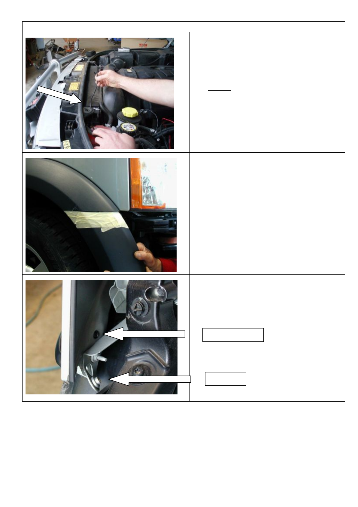
02-08-12 Page 9 of 23 3787827
VEHICLE PREPARATION
14. With all the wiring connections now
made , feed the harness down so that it
sits neatly and retain in place with the
cable ties provided .
Note :- Ensure all wiring will not rub or
touch on any metal parts , sharp
edges and hot or moving parts .
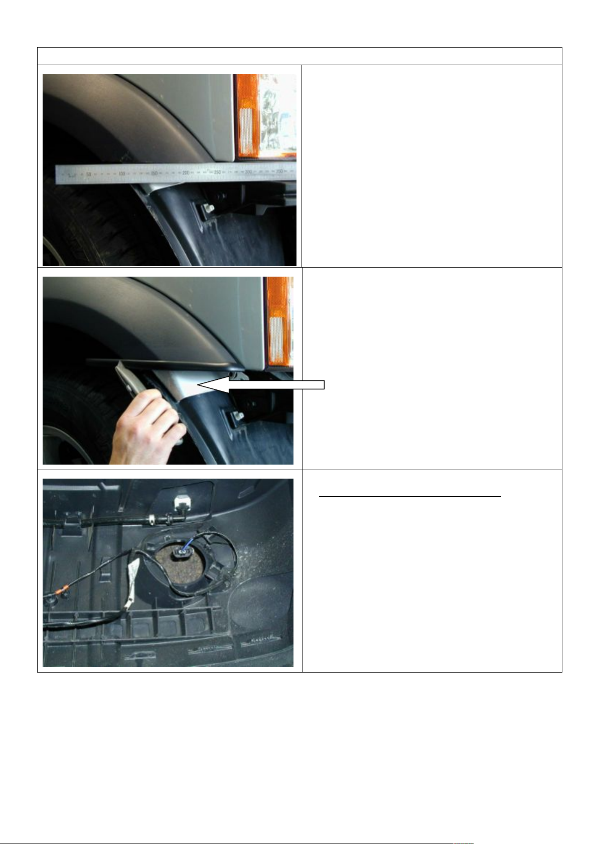
15. Replace the headlight to gain a visual
reference of the line to be cut. Mask the
flare along the line of the headlight.
16. Remove the headlight and remove the
flare.
17. Cut the flare along the line of the
masking tape.
NOTE: Be careful not to cut too much off
the inner tab that attaches the flare to the
guard.
18. Replace the flares making sure to
replace the screw at headlight level.
19. Bend the tag that hangs down below the
line of the guard up and out of the way.
Bend tag
Replace screw
Page 10
02-08-12 Page 10 of 23 3787827
VEHICLE PREPARATION
20. Once satisfied with the cut of the flare,
replace the headlight and the grill.
21. Clean the flare where it has been cut
and attach the plastic side moulding to
the flare.
22. Cut the plastic side moulding with a
Stanley knife along the back edge of the
flare.
23. It is recommended that the lower portion
of the bodywork below the flare cut off
be painted black. Clean the surface with
prep wash then mask the surrounding
area.
If fog lights not fitted go to step 26
24. Using a TORX bit, remove the fog lights
from the bumper bar and keep the six
retaining screws.
25. Remove the fog light wiring loom from
the bumper bar.
Page 11
02-08-12 Page 11 of 23 3787827
VEHICLE PREPARATION
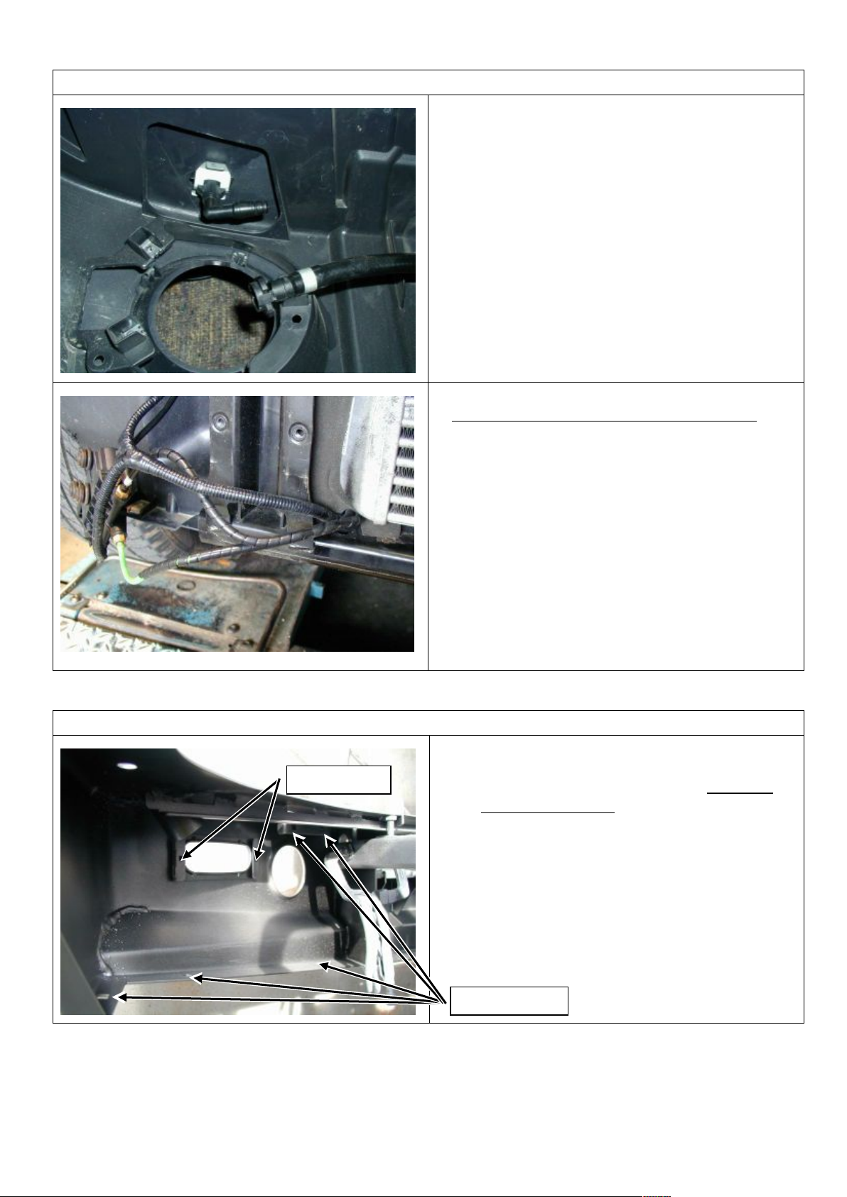
26. Unclip the headlight washer hose from
the nozzle and remove both the headlight
washers and the hose.
If air suspension not fitted go to step 28.
27. Cut the supplied spiral wrap in half. Wind
the spiral wrap around the two lower air
hoses that connect to the suspension
actuators.
BULL BAR SETUP
28. Fit both the right and left hand buffers to
the bar using M6 flange nuts. DO NOT
OVER TIGHTEN.
29. Fit 14 M6 cage nuts (10 into the wings
and four into the main pan) and four
nylon plugs to the bar.
Nylon plugs
M6 cage nuts
Page 12
02-08-12 Page 12 of 23 3787827
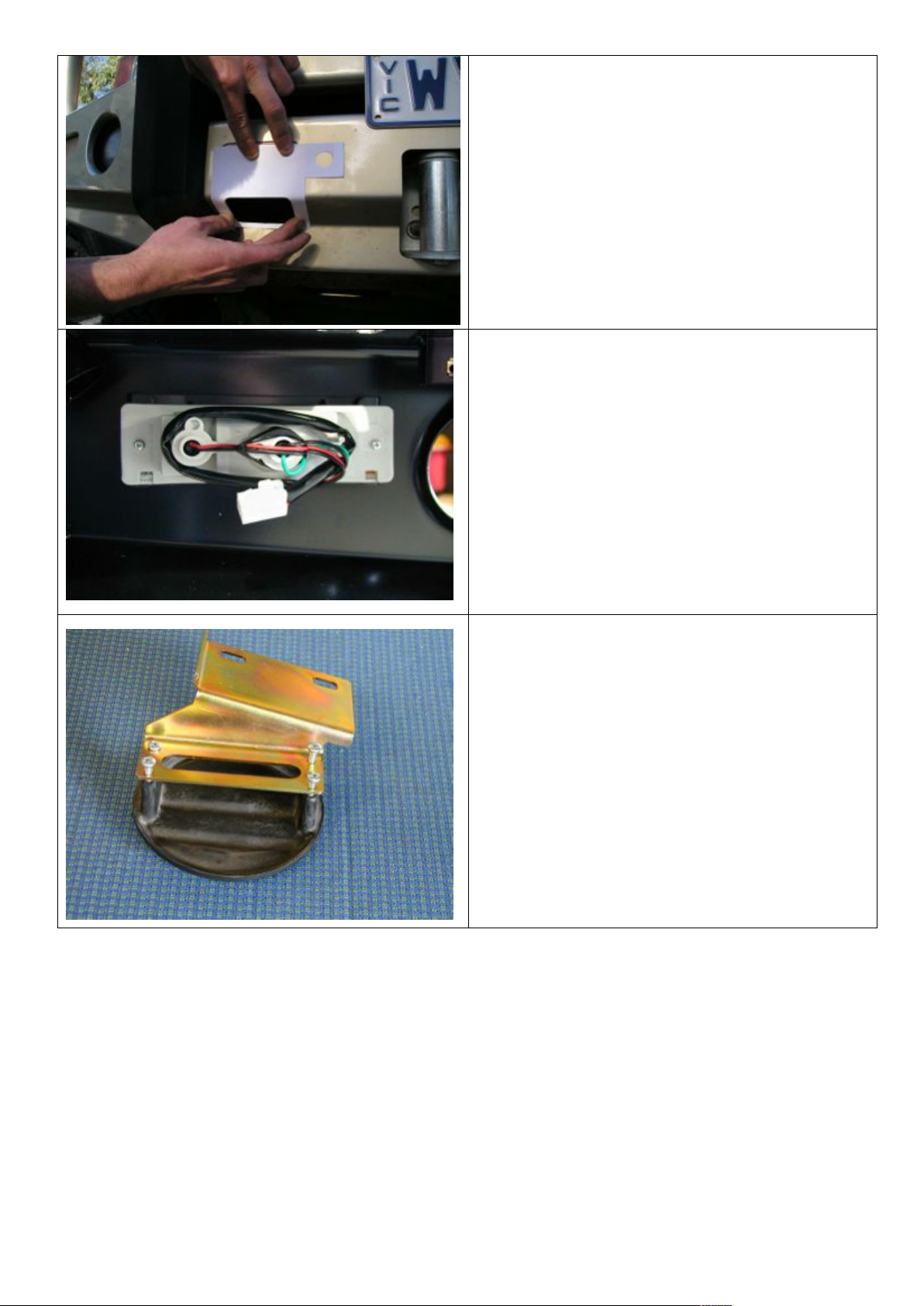
30. If vehicle is fitted with parking sensors
cut out templates supplied with
instructions. Place outer templates over
indicator recess and inner templates over
high lift jack opening as shown. Mark
holes with a felt tip pen. Drill 16mm holes
in marked positions. File or die-grind
slightly to achieve a snug fit (not a tight
fit). De-burr and paint when done.
31. Install the indicators into the bar using
the self tapping screws (8-ABX1”pan
head) supplied with the fitting kits.
Discard the screws supplied with the
indicators.
NOTE: The indicators should be installed
with the drain holes at the bottom
32. If there are no fog lights fitted to the
vehicle, fit the fog light insert supplied to
the bar. Fit the fog insert bracket to the
fog light insert with the eight pan head
screws as shown opposite.
Page 13
02-08-12 Page 13 of 23 3787827
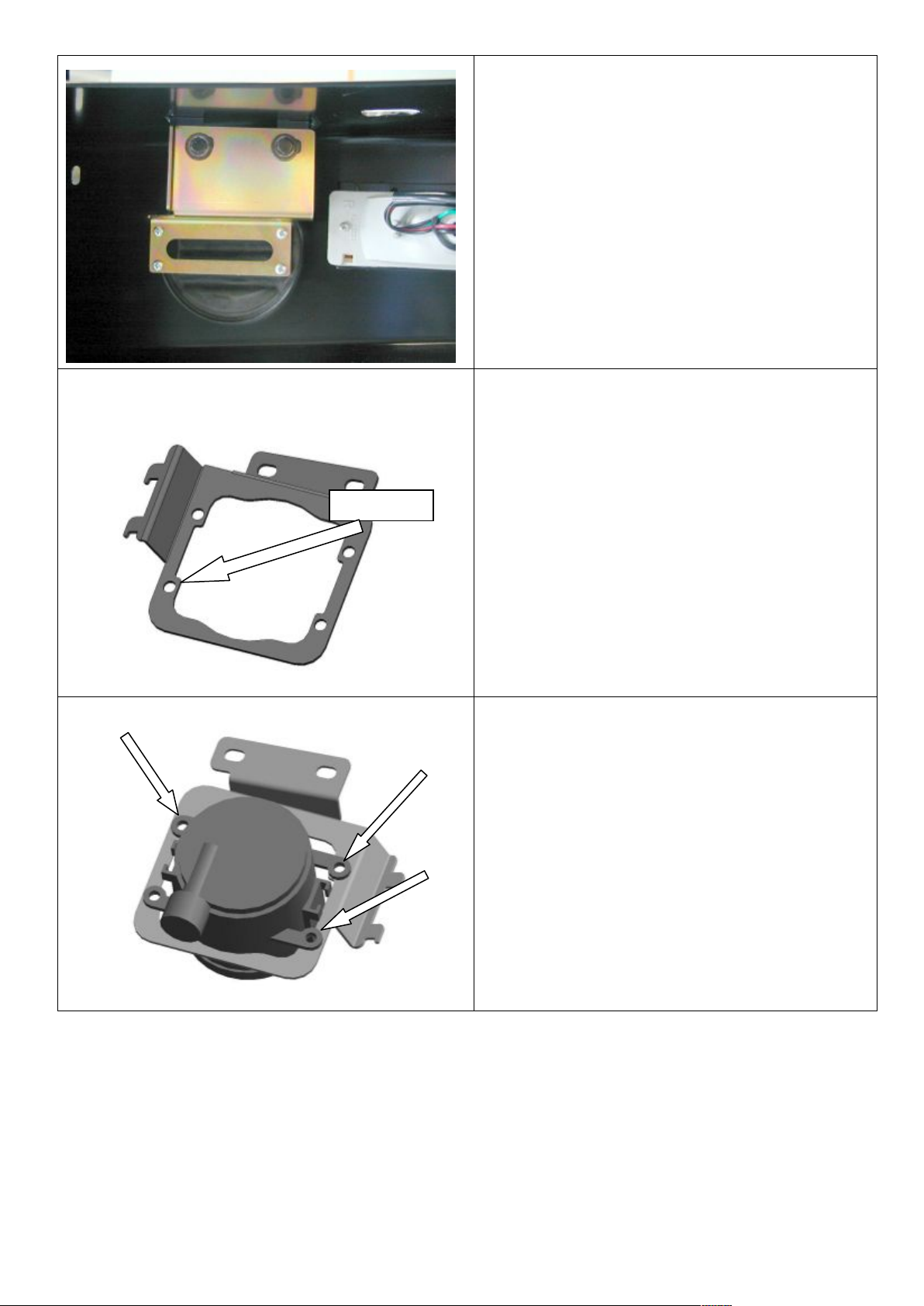
33. Fit the fog light insert assembly to the
bar using two M6 x 20mm black bolts,
M6 flat black washers and M6 black
spring washers.
34. For vehicles with fog lights, fit the U-type
nuts to any three of the four holes on the
fog light bracket.
35. Using the original TORX head screws
removed with the fog lights earlier; fit the
fog lights into the fog light brackets.
U-type nuts
Page 14
02-08-12 Page 14 of 23 3787827
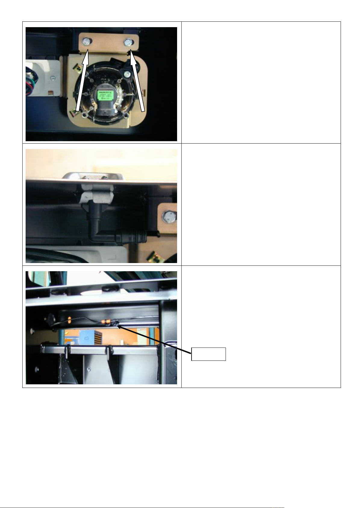
36. Clip the fog light assembly into the
indicator bracket and fix in place using two
M6 x 20mm black bolts, M6 flat black
washers and M6 black spring washers.
37. If fitted, re-fit the head light washers into
the bar using the original spring clips.
38. Run the fog light wiring loom through the
bullbar. Remove the plastic clips as
necessary.
Remove
Page 15
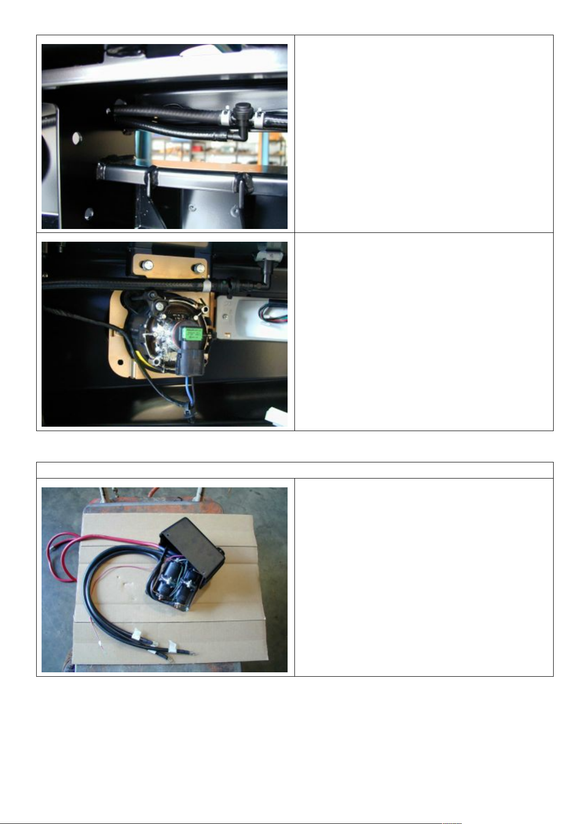
02-08-12 Page 15 of 23 3787827
39. Run the hoses removed from the bumper
through the bar being careful not to kink
any lines.
40. Secure to bar with a few cable ties.
41. Fit the fog light loom to the fog light and
fit the washer hose to the headlight
washer. Cable tie the head light loom and
the washer hose together making sure
they are away from sharp edges.
WINCH FITMENT
IF NOT FITTING A WINCH GO TO STEP 53
42. If fitting a Warn winch, replace the three
cables in the control box marked A, F1
and F2 with the three 850mm cables
from the fitting kit. Mark the new cables
as per the original cables.
Page 16
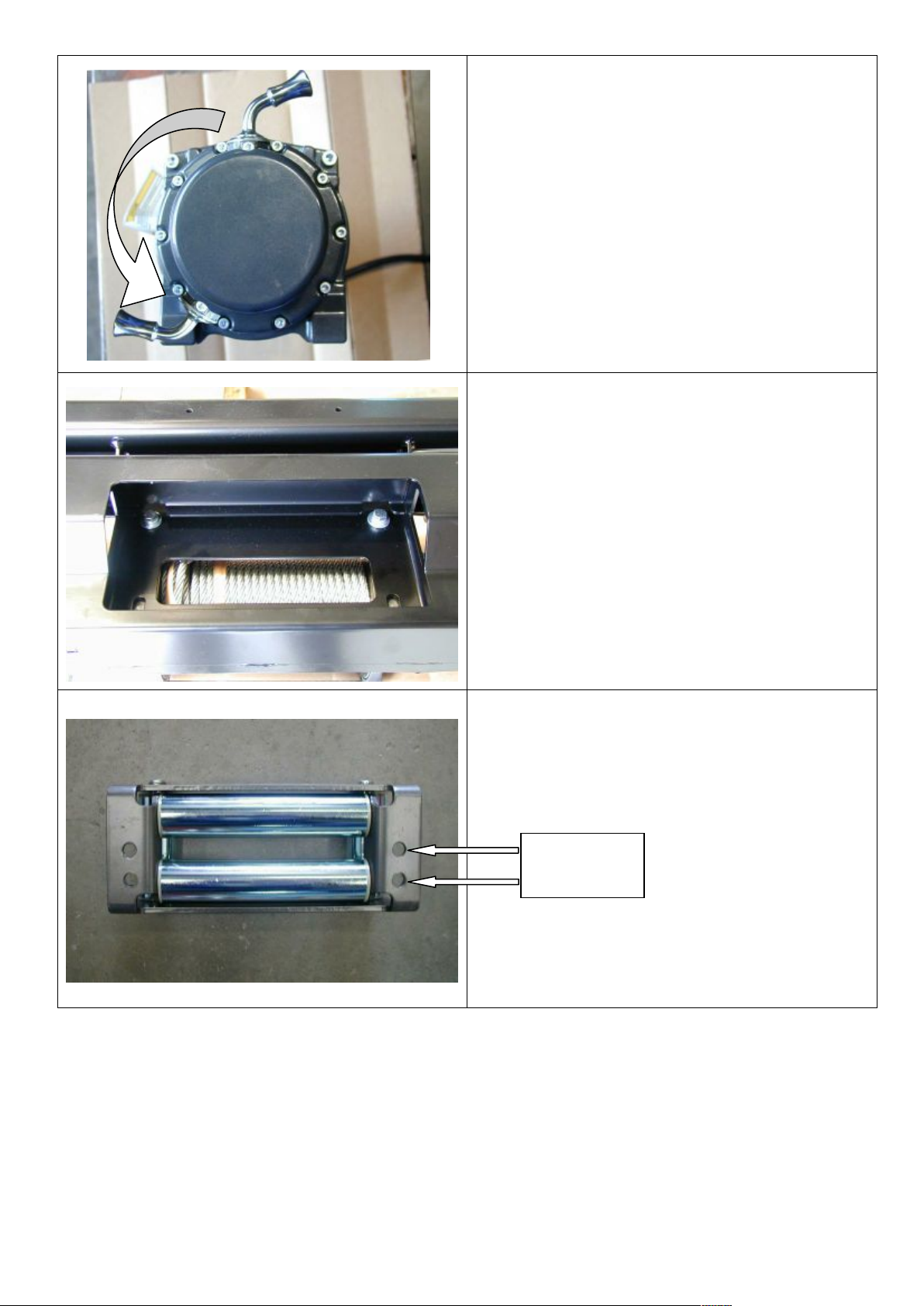
02-08-12 Page 16 of 23 3787827
43. Remove the cap head screws retaining
the gearbox to the winch drum. Carefully
lift and rotate the gearbox 144 degrees
counter clockwise (four hole spacings)
and re-fit the cap screws.
44. Lay the winch on a suitable surface and
place the bull bar on top so that the wire
rope will feed from the bottom.
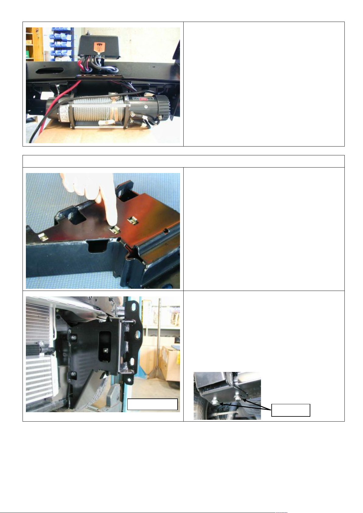
45. Usingtwo3/8”x11/2”bolts,M10flatand
spring washers, attach the bull bar to the
winch through the top two holes
46. Using a 12mm drill bit, drill two new holes
in the roller fairlead 25mm below the
original holes.
Drill the new
hole 25mm
below original
Page 17
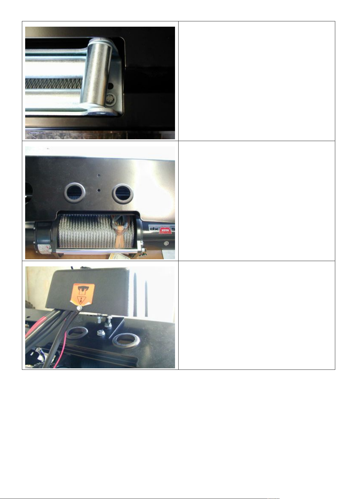
02-08-12 Page 17 of 23 3787827
47. Remove the cir-clips from the bottom of
the vertical rollers of the fairlead and
push the pin upwards. Push the vertical
rollersinwardsundusingtwo3/8”x1¾”
bolts M10 flat and spring washers, attach
the roller fairlead to the bar.
48. Replace the circlips on the vertical rollers.
49. Insert the two rubber grommets into the
top face of bull bar.
50. Attach the control box to the control box
bracket.
51. Fit the control box to the bar with two M8
x 20mm bolts, M8 flat washers and M8
flange nuts.
Page 18
02-08-12 Page 18 of 23 3787827
52. Run the cables through the rubber
grommets and connect to the winch as
per wiring diagram supplied with the
winch.
53. Using cable ties, fix the cables away from
any moving, sharp or hot surfaces.
BULL BAR FITMENT TO VEHICLE
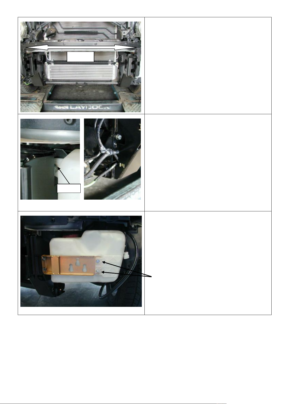
54. Fit the six M8 cage nuts to the impact
absorbers.
55. Mount both the impact absorbers to the
vehicle using four (a side) M8 x 25mm
bolts, M8 flat and spring washers in the
front face, two (a side) M10 x 35mm
bolts, M10 flat washers, M10 spring
washers and M10 flange nuts in the
underside.
( DO NOT TIGHTEN)
M10 bolts
Left hand side
Page 19
02-08-12 Page 19 of 23 3787827
56. Centralise the mounts so that the surface
that mounts to the bull bar is vertical.
57. The mounts must be positioned so that
there is 815mm gap between the outside
surfaces of the bull bar mounting face.
58. Tighten all the bolts.
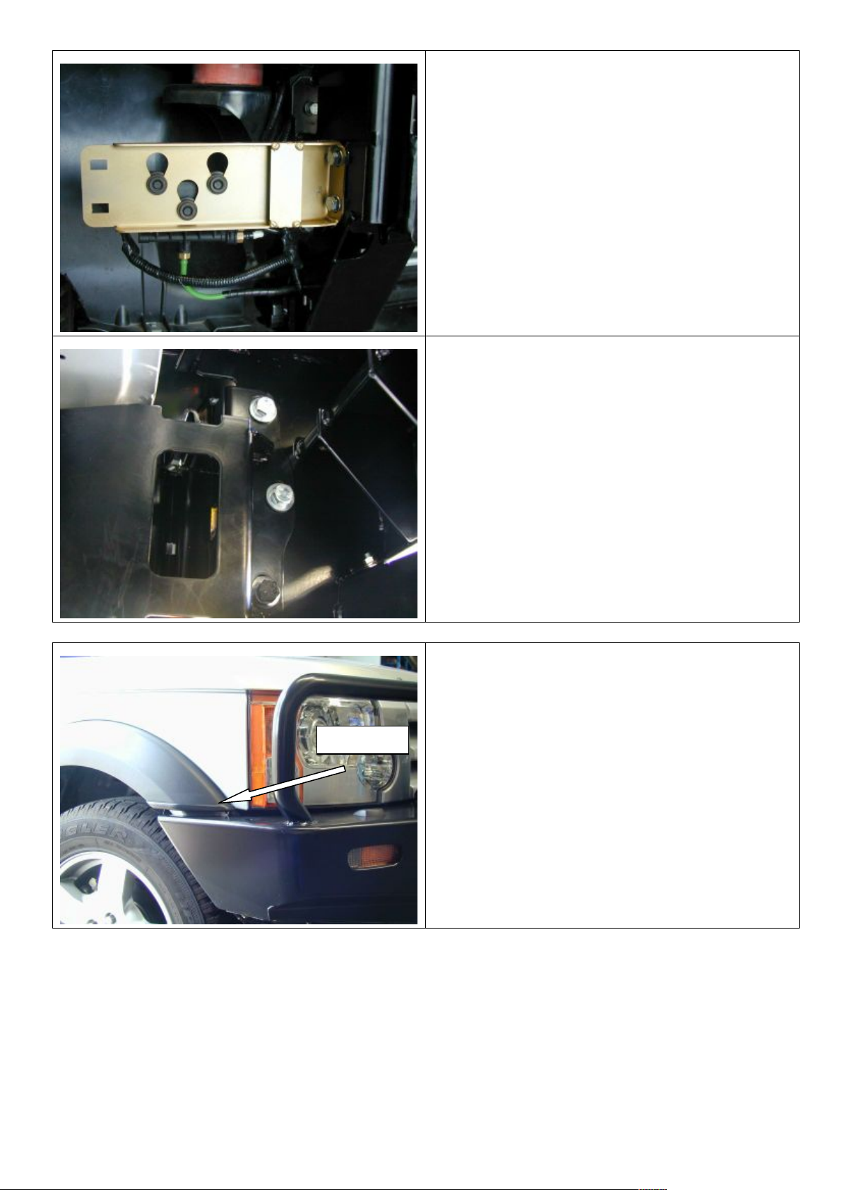
59. On the left hand side, the washer bottle
sits in front of the mount face. (Make sure
that the metal spacer in the washer bottle
tag remains in place)
60. On the right hand side, the air lines on air
suspension models run through the gap
in the impact absorber backing plate.
61. Install two M6 cage nuts into one of the
Washer bottle brackets.
62. Attach the washer bottle bracket wit the
cage nuts installed to the left hand side
impact absorber using two M8 x 20mm
bolts, M8 flat and spring washers.
63. Fix the washer bottle to the bracket using
two M6 x 20mm black bolts, M6 flat black
washers and M6 black spring washers.
815mm
Spacer
Page 20
02-08-12 Page 20 of 23 3787827
64. Attach the washer bottle bracket without
the cage nuts to the right hand side
impact absorber using two M8 x 20mm
bolts, M8 flat and spring washers.
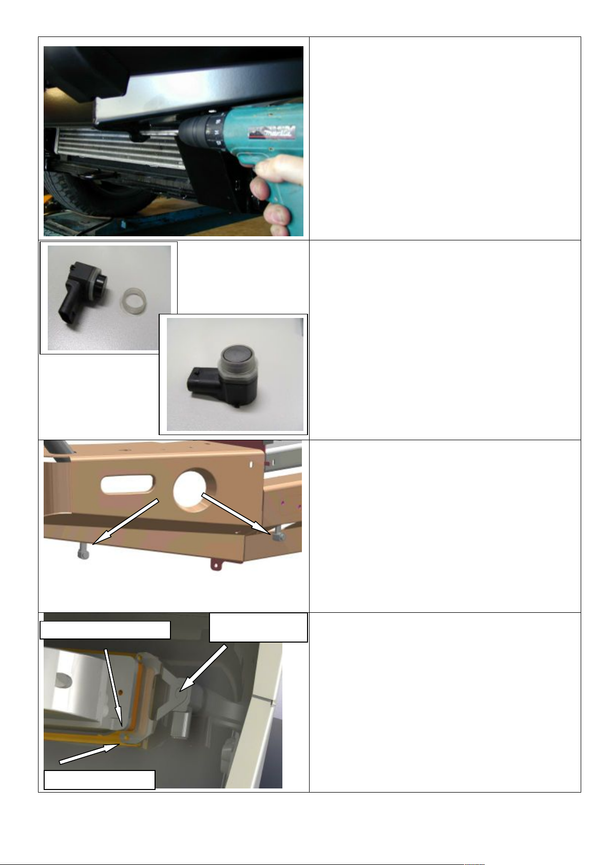
65. On vehicles equipped with air
suspension, attach the solenoid pack to
the bracket.
66. With the help of another person, lift the
bull bar into position and fix in place
using 3 (a side) M10 x 35mm bolts, M10
flat washers, M10 spring washers and
M10 flange nuts. Do not tighten.
67. Adjust the bar so there is approximately a
10mm gap between the bull bar wing and
the bottom of the flare. When the bar is in
the correct position tighten the bolts.
10mm gap
Page 21
02-08-12 Page 21 of 23 3787827
68. Using a 10mm drill bit; drill the pinning
bolt hole using the hole in the upright as
a guide.
69. Fix in place using a M10 x 35mm bolt,
M10 flat washer, M10 spring washer and
M10 flange nut. Repeat for the other
side.
70. Connect the indicators to the indicator
loom. Re-connect the fog light loom,
headlight washer hose and the ambient
temperature sensor.
71. Fit original rubber grommets to sensors
as shown.
72. Plug sensors into loom. Hang down from
vehicle as shown facing forward. Test
vehicle parking system is operating
correctly.
73. Start from right to left fit and test one
sensor at a time. Fit small blanking
grommets to outer brackets making sure
the larger area faces the sensor. Fit outer
brackets as shown. Secure to indicator
mount using small self tapping screws. If
you wish to achieve a tighter hold bracket
may be bent slightly. Test sensor system.
FIT GROMMET TO
BRACKET
MOUNTING BRACKET
LARGER FOOT TO BOTTOM
Page 22
02-08-12 Page 22 of 23 3787827
74. Inner sensor mounting. If sensors are
activating try to rotate slightly and re-test.
Once all sensors are fitted and working
correctly apply a small amount of sensor
safe silicone to both bracket and bar to
limit movement of sensor.
75. If no winch is fitted fit fairlead cover panel
now. Insert 4 of the M10 cage nuts as
shown and secure from inside bar (winch
mounting holes) using 4 X M10 SEMS
bolts.
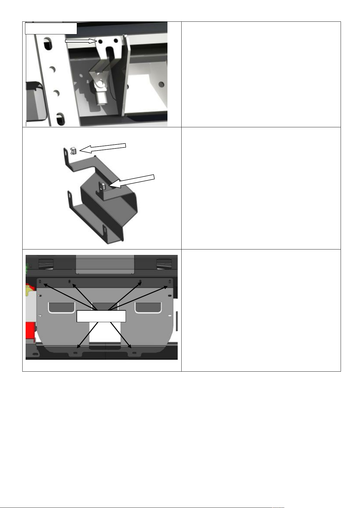
76. Fit the stone tray to the bar using six M6
x 20mm black bolts, M6 black flat
washers and M6 black spring washers.
M6 black bolts
M6 FASTENERS
Page 23
02-08-12 Page 23 of 23 3787827
WASHER BOTTLE GUARD FITMENT TO BULL BAR
77. Fit two M6 cage nuts to back surface of
guards. Fit the washer bottle stone
guards to both sides of the bull bar .
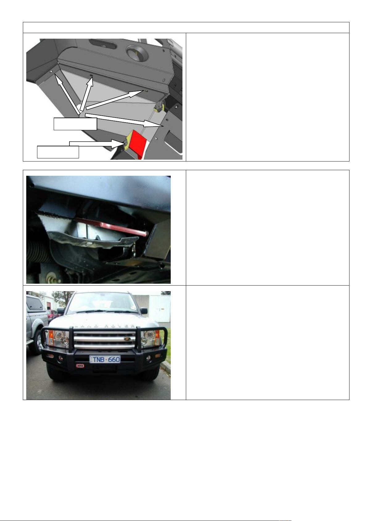
78. Use the three M6 x 20mm black bolts,
M6 black flat washers and M6 black
spring washers to attach the guards to
the wing along the front and side edges .
79. Attach the M8 x 20mm black bolt , M8
black flat washer and M8 black spring
washer to attach the guard to the impact
absorber as shown .
80. Trim the inner guard in line with the lower
edge of the washer bottle cover .
81. Using the washer bottle guard as a
template mark the position of two cage
nuts located on the rear fold with a paint
marker onto the fender liner .
Drill Using a 8 mm drill bit - drill the two
holes .
82. To fit the license plate to the bar, first
push two nylon plugs into the front face
of the top pan. Fit the license plate using
two 8-18 x 20mm tek screws .
83. Ensure all lights are functioning correctly
and all bolts are fully tightened .
Also supplied in the kit are two 16mm plugs. The two plastic plugs are for the holes in the top
surface of the wings if no CB aerials are fitted.
M8 BOLT
M6 BOLTS
 Loading...