


INSTALLATION GUIDE
RD100
DANA 30, 27 SPLINE, 3.73 & UP
Part No. 2102100
Revision Date 08/04/03
Copyright © 2002 by ARB Corporation Limited

No liability is assumed for damages resulting in the use of the information contained herein.
ARB Air Locker Air Operated Locking Differentials and Air Locker are trademarks of ARB Corporation Limited.
Other product names used herein are for identification purposes only and may be trademarks of their respective owners.
ARB 4x4 ACCESSORIES
Corporate Head Office
42-44 Garden St |
Tel: |
+61 (3) 9761 6622 |
Kilsyth, Victoria |
Fax: |
+61 (3) 9761 6807 |
AUSTRALIA |
|
|
3137 |
|
|
Australian enquiries |
|
sales@arb.com.au |
North and South American enquiries |
sales@arbusa.com |
Other international enquiries |
exports@arb.com.au |
|
|
www.arb.com.au

Table of Contents:
1 Introduction |
3 |
|
1.1 |
Pre-Installation Preparation |
3 |
1.2 |
Tool-Kit Recommendations |
4 |
1.3 |
Assembly Type Identification |
5 |
2 Removing the Existing Differential |
6 |
|
2.1 |
Vehicle Support |
6 |
2.2 |
Differential Fluid Drain |
6 |
2.3 |
Disconnecting the Axles |
7 |
2.4 |
Marking the Bearing Caps |
8 |
2.5 |
Checking the Current Backlash Amount |
9 |
2.6 |
Removing the Differential Center |
10 |
3 Installing the Air Locker |
12 |
|
3.1 |
Insuring Adequate Oil Drainage |
12 |
3.2 |
Installing the Carrier Bearings |
13 |
3.3 |
Approximate Backlash Shimming |
14 |
3.4 |
Mounting the Ring Gear |
16 |
3.5 |
Drilling and Tapping the Bulkhead Port |
17 |
3.6 |
Assembling the Seal Housing |
19 |
3.7 |
Pre-Load Shimming |
20 |
3.8 |
Reinstalling the Bearing Caps |
25 |
3.9 |
Checking the Backlash |
26 |
3.10 |
Setting Up the Bulkhead Fitting |
27 |
3.11 |
Profiling the Seal Housing Tube |
29 |
4 Installing the Air System |
30 |
|
4.1 |
Mounting the Solenoid |
30 |
4.2 |
Running & Securing the Air Line |
32 |
4.3 |
Connection to the Bulkhead Fitting |
33 |
5 |
Mounting & Connecting the Electrical System |
35 |
|
|
5.1 |
Mounting the Actuator Switch(es) |
35 |
|
5.2 |
Wiring the Actuator System |
36 |
|
|
|
|
6 |
Testing & Final Assembly |
40 |
|
|
6.1 |
Leak Testing |
40 |
|
6.2 |
Reinstalling the Axles |
40 |
|
6.3 |
Testing the Air Locker Actuation |
41 |
|
6.4 |
Re-Sealing & Filling the Differential |
41 |
|
6.5 |
Post-Installation Check List |
42 |
|
|
|
|
7 |
Parts List |
43 |
|
|
7.1 |
Exploded Assembly Diagram |
43 |
|
7.2 |
Itemized Parts List |
44 |
1
2

1 Introduction
IMPORTANT :
BEFORE ATTEMPTING TO DISMANTLE YOUR VEHICLE FOR THIS INSTALLATION, PLEASE READ THIS INSTALLATION GUIDE IN ITS ENTIRETY, AS WELL AS ALL APPLICABLE SECTIONS OF YOUR VEHICLE MANUFACTURER’S SERVICE MANUAL.
1.1 Pre-Installation Preparation
This booklet is to be used in conjunction with your vehicle manufacturer’s service manual. ARB endeavors to account for every possible variation in vehicle model when publishing its installation guides, and guides are updated regularly as new model information becomes available, however, the rapid and globally varied release of some vehicles makes it difficult to insure that your vehicle model has been accurately accounted for. In the case of any technical discrepancies between this guide and your service manual, we strongly advise that you adhere to the specifications and techniques as documented in your service manual.
Although your ARB Air Locker comes complete with all the step by step instructions you will need to supplement your vehicle manufacturer’s service manual and install your new differential, ARB recommends that you have your Air Locker installed by a trained professional. Many ARB distributors around the world have been fully instructed in Air Locker installations by ARB, and have gained a wealth of experience and skill from years of performing similar installations.
Once you begin this installation your vehicle will be immobile until all steps of the installation are complete. Make sure your Air Locker kit is the correct model for your vehicle and that it contains all of the parts listed on back cover of this booklet. Also be sure you have appropriately equipped yourself with all the necessary tools, parts, and materials to complete this installation (see section 1.2 Tool-Kit Recommendations), and that you have allowed for an appropriate amount of vehicle down time.
HINT : Place a  mark inside each of the c symbols as you complete each step. It is very important NOT to miss any of the steps!
3

1 Introduction
1.2 Tool-Kit Recommendations
Below is a list of tools and supplies you may need to complete this installation. Requirements for your vehicle may vary. Please consult your vehicle service manual for additional recommendations.
1.2.1 Tools
cStandard automotive sizes (metric and/or imperial) of sockets, wrenches, Alan keys, and drills.
cA dial indicator or other suitable measuring tool for checking ring & pinion backlash.
cA standard automotive feeler gauge.
cA razor knife to cut the nylon tubing.
cA differential housing spreader, to facilitate removal of the carrier. (not required on aluminum housings)
cA torque wrench. (See vehicle service manual for required torque range.)
cA lubricant drain reservoir.
cSuitable measuring tools to measure a differential for pre-load and/or backlash shimming. (See Section 3.3)
cA 11.2mm [7/16”] drill and ¼” NPT tap for bulkhead fitting installation.
cAn automotive bearing puller (2 jawed is recommended) or a differential carrier bearing puller.
cA bearing press or arbor press.
1.2.2 Supplies
cThread lubricant/sealant compound for pressure fittings (e.g., LOCTITE #567 Teflon paste)
cThread locking compound (e.g., LOCTITE #272)
cEither a replacement gasket, or gasket sealant, for your differential cover.
cA sufficient volume of differential oil to completely refill your housing. (see the ARB Air Locker Operating and Service Manual for recommended lubricants)
cA soap and water mixture to test for air leaks.
cTeflon paste.
4

1 Introduction
1.3 Assembly Type Identification
IMPORTANT:
Sections 2 and 3 of this installation guide have been written to accommodate two different Dana 30 applications:
Athe Independent Front Suspension (IFS) type with an aluminum housing (Refer to Fig.1.)
Bthe live axle Salisbury type with a cast iron housing. (Refer to Fig.2.)
To eliminate confusion, you should identify which figure your vehicle matches with. The section numbers within the guide that refer ONLY to the IFS type have been suffixed with an ‘ A ’, and those that refer ONLY to the live axle type have been suffixed with a ‘ B ’.
PLEASE IGNORE ALL SECTIONS WHICH DO NOT APPLY TO YOUR APPLICATION
A
Figure 1.
B
Figure 2.
5

2 Removing the Existing Differential
2.1 Vehicle Support
cSafely secure the vehicle on a hoist. We recommend supporting the vehicle on a chassis hoist to keep the differential area at a convenient working height and to leave the wheels and axles free to be rotated and removed.
cOnce supported off the ground, release the parking brake and leave the vehicle in neutral. Chock the wheels if necessary.
2.2 Differential Fluid Drain
HINT : This is a good time to check for metal particles in your oil, on your drain plug, or in the bottom of the housing which may indicate a worn bearing or differential component.
2.2.1 A IFS Fluid Drain
cRemove any skid plates covering the bottom of the front axle area and position a fluid drain reservoir under the differential.
cRemove the threaded drain plug and completely drain all differential oil from the housing.
cFinger-tighten the drain plug back in to prevent drips during the removal of the axle assembly.
2.2.2 B Live Axle Fluid Drain
cClean around the differential cover plate seal to prevent dirt from entering the differential.
cPosition a fluid drain reservoir under the differential and loosen all differential cover plate retaining bolts.
cGently pry the cover plate away from the differential housing to completely drain all differential fluid.
cOnce drained, remove the differential cover plate.
6

2 Removing the Existing Differential
2.3 Disconnecting the Axles
2.3.1 A IFS CV Shafts
cRemove the wheels, and brakes according to your vehicle manufacturer’s service manual.
cDisconnect the drive shaft from the differential drive flange.
cDisconnect the struts (shocks) from the lower control arms.
cRemove the forked strut mounts off of the bottoms of the strut cylinders.
cDisconnect the upper and lower ball joints.
cTap the CV shafts outward to disconnect the retaining clips, and draw the knuckle joints outward until you can completely disengage the spline of the CV shafts from the differential housing.
NOTE : The oil seals are delicate and can be easily damaged. Support the weight of the CV shaft when drawing them out of their sockets in the housing.
cCompletely remove the differential assembly from the vehicle.
cSecure the differential assembly to a work bench.
cRemove the front access cover plate.
2.3.2 B Live Axle CV Shafts
IMPORTANT :
Collision damage or heavy off-road use of your vehicle in the past may have resulted in some degree of bending in the axle. Any misalignment of the axle tubes may result in excessive wear and/or failure of your differential and axle shafts. ARB strongly recommends that you have your axle assembly inspected for concentricity and straightness before installing your Air Locker.
cRemove the wheels, and brakes according to your vehicle manufacturer’s service manual.
cDisconnect the drive shaft from the differential drive flange.
cDisconnect the upper and lower ball joints.
cDraw the knuckle joints outward until you can completely disengage the spline of the CV shafts from the differential housing.
NOTE : The oil seals are delicate and can be easily damaged. Support the weight of the CV shaft when drawing them out of their sockets in the housing.
7
2 Removing the Existing Differential
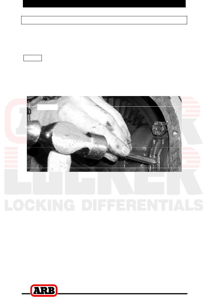
2.4 Marking the Bearing Caps
cUsing a pointed center punch, gently mark the bearing caps in a way that will enable you to know which cap is ‘LEFT’ and which cap is ‘RIGHT’, which way is ‘UP’ and which way is ‘DOWN’. (Fig.3.)
HINT : Many installers choose to make one punch mark on the left hand side of the left hand bearing cap and one
similar punch mark on the housing at close proximity to the cap mark. The right hand side is then designated with two punch marks on the right hand side of the cap and two similar punch marks on the housing.
Figure 3.
8
2 Removing the Existing Differential
2.5 Checking the Current Backlash Amount
IMPORTANT:
This step is a precautionary measure recommended by ARB due to the fact that some after market ring and pinion sets have been manufactured to run with different backlash settings than those specified by your vehicle manufacturer. Although ARB must recommend you set backlash according to your service manual guidelines, we also advise that you compare the backlash measurements taken here to the recommended backlash settings in your vehicle service manual. Measurements found to be outside of your service manual recommendations may indicate the need to deviate from those settings in order to achieve quiet running with a good contact mark.
Refer to your vehicle service manual or your local authorized ARB installer for more information.
c Set a depth indicator on one of the ring gear teeth as in figure 4.
Figure 4.
cWhile supporting the pinion gear by holding the drive shaft flange, rotate the differential in both directions while observing the maximum variation in depth from the indicator (i.e., the highest value minus the lowest value). This value is referred to as the ring and pinion backlash.
cRotate the differential center 90° and measure again for accuracy.
cRecord the average of all measurements.
9

2 Removing the Existing Differential
2.6 Removing the Differential Center
2.6.1 A Cast Aluminum Housings
IMPORTANT:
YOU MUST NOT SPREAD THE HOUSING ON
ALUMINUM IFS ASSEMBLIES.
IFS models like the Jeep Liberty (KJ) were made with an aluminum differential housing (See Figure 1.) and therefore must not be spread like a cast iron housing. Spreading an aluminum housing could cause irreparable damage to the housing and is therefore strongly advised against.
cRemove both bearing caps.
cCarefully remove the differential center by pulling or prying forward.
NOTE : Keep track of which shims came from which side as it will be important to match them to their original positions for measurements later.
NOTE : The differential center is heavy and quite difficult to handle when covered in oil. Take care not to drop it.
2.6.2 B Cast Iron Housings
IMPORTANT:
YOU MUST SPREAD THE HOUSING ON CAST IRON MODELS
Spreading the differential housing with a differential case spreader is a step which is critical to set up bearing pre-load on cast iron differential housings (See Figure 2.). Improper pre-load will result in undue bearing wear, increased stresses in the differential center, increased running noise, and ultimately, ring and pinion gear damage.
cRemove both bearing caps.
cCarefully spread the housing (Fig.5.) enough to remove the differential center. (Refer to your vehicle’s service manual).
NOTE : Do not spread the housing more than 0.50mm [0.020”].
10

2 Removing the Existing Differential
HINT : Be sure not to mix up the left and right hand bearing cups. Later it will be necessary to know which cup came from which side.
cOnce the housing has been adequately spread, the differential may be removed by pulling forward on the differential carrier.
Figure 5.
NOTE : The differential center is heavy and quite difficult to handle when covered in oil. Take care not to drop it.
cRelieve any tension on the spreader immediately after the differential has been removed.
11

3 Installing the Air Locker
3.1 B Insuring Adequate Oil Drainage
IMPORTANT:
Some Salisbury axles were manufactured with poor oil drainage between the axle tubes and the differential housing. This can often result in one of the axle tubes filling up with differential oil while running. In most cases this will result in a blocked air vent which will cause the differential housing to pressurize and expel oil from the axle seals at the wheels or force oil into the air system of the Air Locker, eventually expelling oil at the solenoid valve. This is a design flaw which was corrected by most automakers in the later releases of their axle assemblies. If no lower drainage point is present in the differential housing then it is critical that you modify the housing to include one.
cInspect the differential housing for the presence of adequate drainage in both axle tubes (refer to Fig.6.).
Figure 6.
cIf no drainage slot is present at the left-hand side (refer to Fig.6.) of the housing at all, then a slot will have to be created as clearance for the seal housing tube (Refer to Section 3.8 Reinstalling the Bearing Caps).
cIf drainage exists but is inadequate then a slot or hole should be cut into the housing on the lower side of the tube(s) to allow oil out of the axle tube area.
12
 Loading...