

Page 1
Part Number:
3462030
Product
Description:
Suited to
vehicle/s:
BULL BAR WINCH TYPE
CHEVROLET C/K 1500-3500 1988-1998 YEAR MODEL
RANGE AND Warn 9,500-15,000lb WINCHES
WARNING
REGARDING VEHICLES EQUIPPED WITH SRS AIRBAG;
When installed in accordance with these instructions, the front protection bar does not affect operation of
the SRS airbag.
ALSO, NOTE THE FOLLOWING:
♦ This product must be installed exactly as per these instructions using only the hardware supplied.
♦ In the event of damage to any bull bar component, contact your nearest authorised ARB stockist.
Repairs or modifications to the impact absorption system must not be attempted.
♦ Do not use this product for any vehicle make or model, other than those specified by ARB.
♦ Do not remove labels from this bull bar.
♦ This product or its fixing must not be modified in any way.
♦ The installation of this product may require the use of specialized tools and/or techniques
♦ It is recommended that this product is only installed by trained personnel
♦ These instructions are correct as at the publication date. ARB Corporation Ltd. cannot be held
responsible for the impact of any changes subsequently made by the vehicle manufacturer
♦ During installation, it is the duty of the installer to check correct operation/clearances of all
components
♦ Work safely at all times
♦ Unless otherwise instructed, tighten fasteners to specified torque
ARB 4x4 ACCESSORIES
Corporate Head Office
42-44 Garden St Tel: +61 (3) 9761 6622
Kilsyth, Victoria Fax: +61 (3) 9761 6807
AUSTRALIA 3137
Australian enquiries sales@arb.com.au
North & South American enquiries sales@arbusa.com
Other international enquiries exports@arb.com.au
www.arb.com.au
Last Rev Date: 27 Mar 2006 Page 1 of 12 Fitting instructions# 3783213
Copyright © 2005 by ARB Corporation Limited. All rights reserved, this document must not be reproduced without the express authority of ARB Corporation Ltd
Page 2
FITTING REQUIREMENTS
REQUIRED TOOLS FOR FITMENT OF PRODUCT:
Metric Spanner and Socket sets Allen key set
Phillips head screwdriver Dia 10.0 drill bit
Electric drill 13mm chuck
HAVE AVAILABLE THESE SAFETY ITEMS WHEN FITTING PRODUCT:
Protective eyewear
NOTE: ‘WARNING’ notes in the fitting procedure relate to OHS situations, where to avoid a
potentially hazardous situation it is suggested that protective safety gear be worn or a safe work
procedure be employed. If these notes and warnings are not heeded, injury may result.
Hearing protection
FASTENER TORQUE SETTINGS:
SIZE Torque Nm Torque lbft
M6 9Nm 4lbft
M8 22Nm 16lbft
M10 44Nm 32lbft
M12 77Nm 57lbft
NOTE: Shipping brackets connecting bull bar to pallet and
associated fasteners are not intended to be reused in fitted
bar assembly.
Last Rev Date: 27 Mar 2006 Page 2 of 12 Fitting instructions# 3783213
Copyright © 2005 by ARB Corporation Limited. All rights reserved, this document must not be reproduced without the express authority of ARB Corporation Ltd
Page 3

PARTS LISTING
APPLICATION PART NO. QTY DESCRIPTION
BRACKET BAR MOUNT LHS
3756825L
3756825R
3199815
3199813
1
BRACKET BAR MOUNT RHS
1
PLATE WELD NUT
2
PLATE WELD NUT TOW HOOK
2
MOUNT BRACKETS TO VEHICLE
WINCH
CONTROL BOX FITTMENT
4581049
4581050
6151255
3756897R
3756897L
6151357
6151321
180302
6151251
6151252
4581051
6151046
6151128
6151017
BLB 460
BLR 460
3756835
10
10
10
1
1
4
4
8
2
2
2
2
2
2
2
1
1
M12 WASHER FLAT
M12 WASHER SPRING
BOLT M12 X 40
REINFORCING BRACKET 2500
REINFORCING BRACKET 2500
BOLT SEMS M10X30
NUT FLANGE M10
CABLE TIE
BOLT M16 X 150
NUT NYLOC M16
WASHER M16
WASHER M6
NUT FLANGE M6
BOLT M6 X 16mm
CABLE EXTENSION NEGATIVE
CABLE EXTENSION POSITIVE
BRACKET STD CONTROL BOX
NUMBER PLATE FITTMENT
BAR TO MOUNT ASSEMBLY
INDICATOR ASSY
6151017
6151128
6151046
3751451
6151255
4581050
4581049
6151321
6151357
6151189
6821151R
6821151L
6151308
6821116
6821152
180701
180302
4
4
4
1
6
6
12
4
4
6
1
1
4
4
2
6
4
BOLT M6 X 16mm
NUT FLANGE M6
WASHER M6
BRACKET NO.PLATE
BOLT M12 X 40mm
WASHER SPRING M12
WASHER FLAT M12
NUT M10 FLANGED
BOLT SEMS M10 X 30mm
NUT M12x1.75
INDICATOR ASSY RHS
INDICATOR ASSY LHS
SCREW SELF TAPPING
NUT NYLON PLUG
LOOM
SCOTCH LOCKS
CABLE TIE
Last Rev Date: 3/4/06 Page 3 of 12 Fitting instructions# 3783194
Copyright © 2005 by ARB Corporation Limited. All rights reserved, this document must not be reproduced without the express authority of ARB Corporation Ltd
Page 4
FITTING PROCEDURE
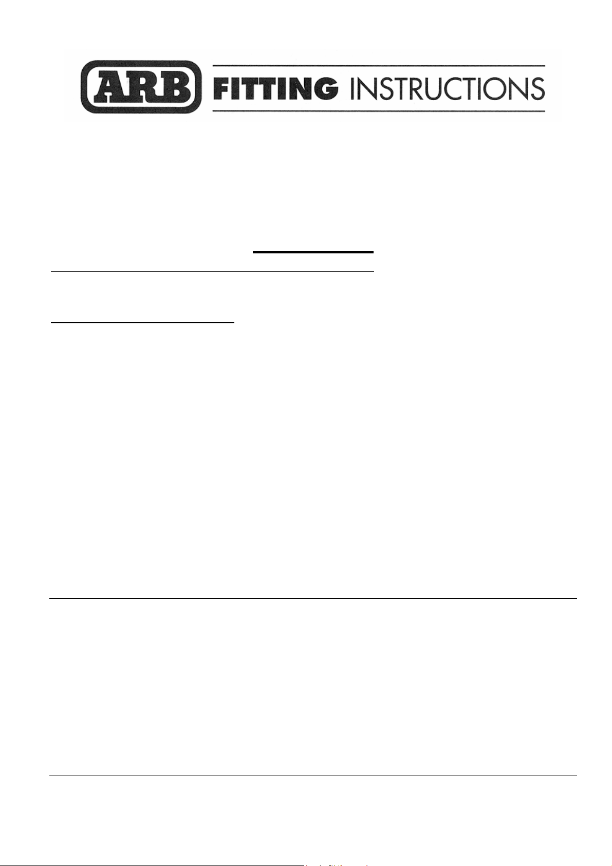
1. Remove the parker/indicator lights
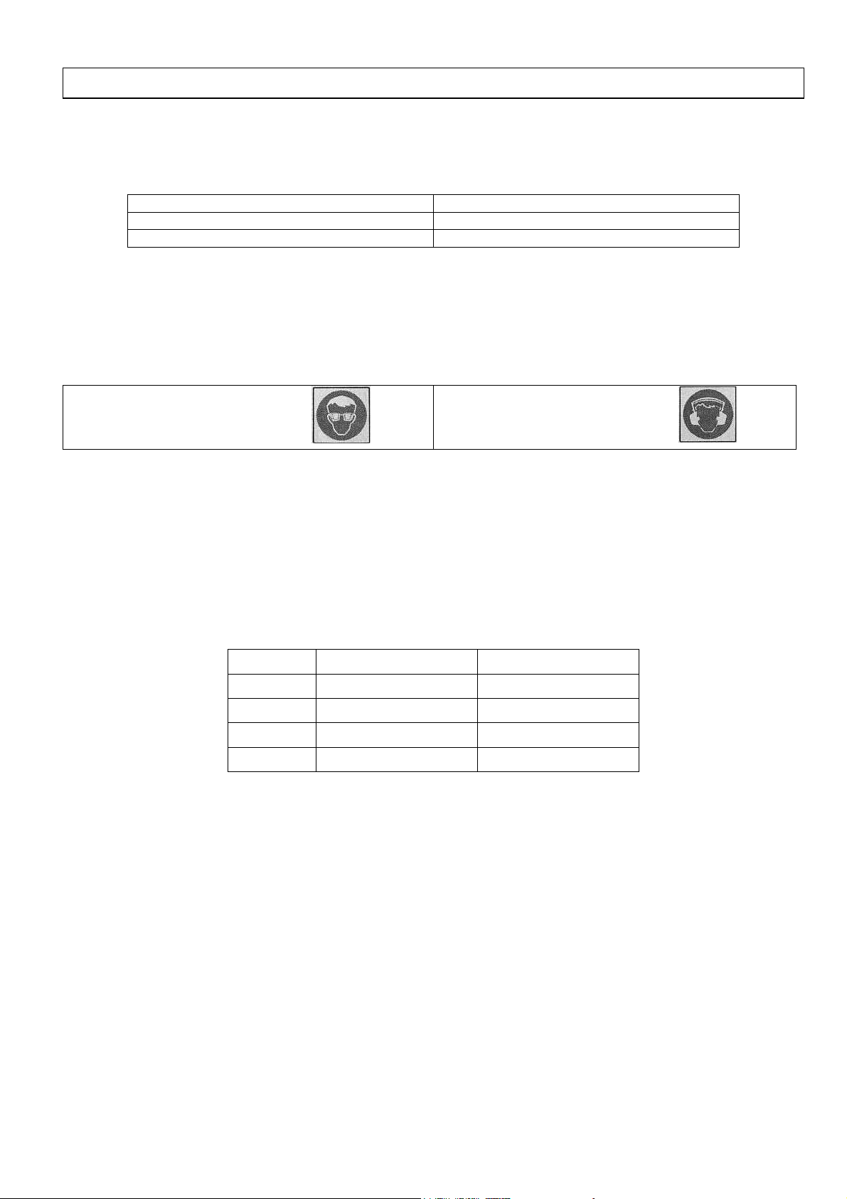
2. Undo and remove the grille. Undo the four
screws across the top and three clips into
lower plastic trim (locations as shown).
Depress clips to release tabs on grille (as
shown at Step 3). One clip is located in the
lower centre of the grille and two are located
outboard below the indicator light positions
located as shown.
Depress this
clip to release
grille tab.
Clip locations
3. Showing clip detail, note that you may need a
large flat blade screwdriver to reach the
middle clip while reaching behind grille.
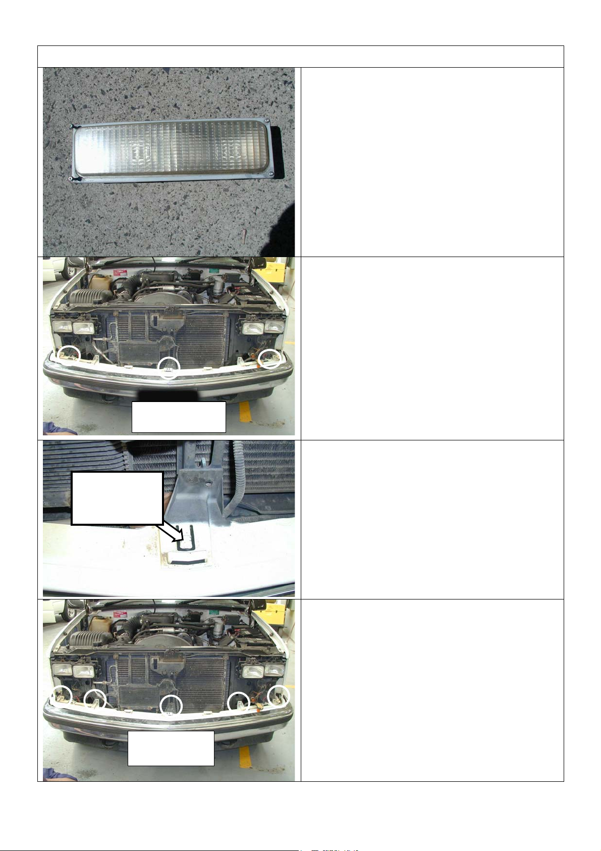
4. Remove plastic trim, this is secured by five
screws located as shown.
Screw
locations
Last Rev Date: 3/4/06 Page 4 of 12 Fitting instructions# 3783194
Copyright © 2005 by ARB Corporation Limited. All rights reserved, this document must not be reproduced without the express authority of ARB Corporation Ltd
Page 5

FITTING PROCEDURE
5. Remove bumper. Undo any electrical
connections to lights in bumper. Undo two
bolts per side retaining the bumper stabilising
bars to the chassis. Loosen only the two
bolts securing the stabiliser bars to the
bumper, the bars should now be able to
swing away from chassis. Undo the three
bolts per side securing the bumper mount
brackets to the chassis. Remove bumper.
6. Remove tow hooks, these will not need to be
refitted.
7. Remove plastic trims from lower front of
guards. At the indicated cut line (along the
moulded feature line approx. 23mm from top
face) cut and retain the lower section of these
trims. Deburr, if necessary touch up and refit
the trims.
NOTE: IF THE CHASSIS IS 2500/3500 THEN FIT
ADDITIONAL BRACKETS AS SHOWN IN STEPS
8 & 9, OTHERWISE PROCEED TO STEP 10.
8. Insert the brackets (note they are handed)
with the short end inside chassis first and the
large flange closest to the centre of the
vehicle.
9. Insert the nut plate and then insert M12 bolt
and washer sets but do not screw the front
NOTE: RHS bracket shown
Last Rev Date: 3/4/06 Page 5 of 12 Fitting instructions# 3783194
Copyright © 2005 by ARB Corporation Limited. All rights reserved, this document must not be reproduced without the express authority of ARB Corporation Ltd
most bolt past the end of the nut. Leave
bolts loose.
Page 6

FITTING PROCEDURE
10. Slide mount brackets into chassis ends
oriented as shown with large flanges
outboard.
11. Position the nut plates with three M12 nuts
fitted into chassis brackets, so that all holes
line up with existing bumper mount holes in
outboard side of chassis. Fit three M12 x 40
bolt and washer sets per side. Do up finger
tight only
NOTE: THIS STEP FOR 1500 CHASSIS ONLY
12. Insert the nut plate with two nuts inside the
bracket and chassis to accept two M12 x 40
bolt sets in the tow hook position. Do up
finger tight only.
13. Nip up all bolts, check that the brackets are
parallel to each other and the front edge of
bracket flange is vertical, if not adjust and
retighten.
Last Rev Date: 3/4/06 Page 6 of 12 Fitting instructions# 3783194
Copyright © 2005 by ARB Corporation Limited. All rights reserved, this document must not be reproduced without the express authority of ARB Corporation Ltd
Page 7

FITTING PROCEDURE
NOTE: THIS STEP FOR 2500/3500 CHASSIS
ONLY
14. Drill with M10 drill bit and fit M10 bolt and
washer sets and flange nuts to pin the flange
of the reinforcing bracket to the side of the
mount bracket body.
Warning: Drilling operations can result in
Warning: Drilling operations can result in
flying metal debris, safety glasses should be
flying metal debris, safety glasses should be
15. Fit grille outboard anchoring brackets as
shown using existing screws.
16. Fit grille centre anchoring bracket as shown
using existing screw.
17. Re-fit grille, use 6mm bolts, panel washers and
flange nuts to secure tabs onto brackets in
three places.
18. Reconnect and refit lights.
Last Rev Date: 3/4/06 Page 7 of 12 Fitting instructions# 3783194
Copyright © 2005 by ARB Corporation Limited. All rights reserved, this document must not be reproduced without the express authority of ARB Corporation Ltd
Page 8

FITTING PROCEDURE
19. Remove lights from cartons and then remove
screws and speed nuts from each light.
These fasteners are not to be reused – new
screws are supplied in the fitting kit.
20. Insert nylon nuts into square holes in light
brackets inside wing area
21. Fit lights using screws supplied in fitting kit,
taking note of RH and LH light bodies, they
are different, marked LH or RH and must be
placed on the correct side of bull bar (drain
holes down).
22. Secure the number plate bracket using M6
bolts, flat washers and flange nuts. Attach the
shorter side to the bullbar and the longer side
to the number plate.
Last Rev Date: 3/4/06 Page 8 of 12 Fitting instructions# 3783194
Copyright © 2005 by ARB Corporation Limited. All rights reserved, this document must not be reproduced without the express authority of ARB Corporation Ltd
Page 9

FITTING PROCEDURE
IF FITTING WINCH, CONTINUE ON THOUGH
STEPS 23 TO 33, 35 & 37.
NOTE: From the factory the 15000lb winch
handle should be in the position shown,
allowing bottom spooling off of cable with the
gearbox handle on the LHS when in bull bar. If
your winch handle will not clear the bull bar
when installed, undo the gearbox end screws.
Lift the gearbox up to just clear locating lugs
and rotate to correct position then retighten,
checking that seals are undamaged and a
draining hole is at bottom centre.
23. Remove cable retaining band and position
cable loop so it will go through roller fairlead
when it is placed in bull bar.
24. Fit control box bracket supplied using M6
bolts and flange nuts as shown.
25. Remove vertical rollers from RFL and set
aside.
NOTE: On some models, the roller fair lead
must be drilled prior to fitment.
26. Mark out as shown then using a 13.0 mm drill
bit, drill two holes as shown in diagram.
Warning: Drilling operations can result in
flying metal debris, safety glasses should be
27. Lay winch on a suitable support table with
mount face up. With the help of an assistant,
lay the bull bar, face up, onto the winch.
28. Position the RFL bracket into position into
the viewer aperture and proceed to bolt up
the winch with original fasteners supplied with
winch.
29. Insert the vertical rollers into the RFL and fix
in position with M16 bolt and nyloc nut sets.
30. Tighten all winch mount bolts.
Last Rev Date: 3/4/06 Page 9 of 12 Fitting instructions# 3783194
Copyright © 2005 by ARB Corporation Limited. All rights reserved, this document must not be reproduced without the express authority of ARB Corporation Ltd
Page 10

A Red
F1
Black
F2
black
31. Fit control box to bracket.
32. Remove cover off control box. Supplied in
fitting kit are 2 x black and 1 x red 460mm
extended cables, mark these accordingly with
the F1, F2 (black) and A (red) markings from
original cables. Remove the 3 x shortest
original heavy duty cables and connect the
extended cables taking care that the
connections are per original configuration.
33. Route and connect the winch control box
cables to the winch motor, taking care that
the cables are connected to the
appropriate terminals. Refer to the Warn
handbook for additional information. Connect
the long winch + & - cables to the vehicle
after
the bar is installed. Refer to the Warn
winch manual for vehicle wiring instructions.
20mm gap
CAUTION: The next step is best achieved
using a safe lifting device or with the help of an
assistant. If a winch is fitted two assistants are
recommended.
34. Fit the bull bar to the vehicle mount brackets.
Use the M12 fasteners to secure it and make
adjustments so there is approximately 20mm
gap from under the grille to the top of the
wing.
35. Tighten the M12 fasteners.
34. Drill and pin the bar to the mounts in 2 x
places per side using M10 drill bit, as shown,
then bolt up using M10 x 30 SEMS bolts and
flange nuts.
Warning: Drilling operations can result in
flying metal debris, safety glasses should be
Last Rev Date: 3/4/06 Page 10 of 12 Fitting instructions# 3783194
Copyright © 2005 by ARB Corporation Limited. All rights reserved, this document must not be reproduced without the express authority of ARB Corporation Ltd
Page 11

If fitting with winch
35. With the winch cable through the roller fair
lead. Mount the hook to the end of the cable.
36. Wire up the indicator and clearance lamp
assemblies. Use scotch locks to splice
cables to existing indicator and clearance
lamp wiring and cable tie securely.
NOTE: Refer to the Warn winch manual for
vehicle wiring instructions.
37. Ensure that electrical cables are installed
well clear of sharp, hot or moving objects.
Secure the winch cables to the vehicle and
winch bumper with the supplied cable ties.
Last Rev Date: 3/4/06 Page 11 of 12 Fitting instructions# 3783194
Copyright © 2005 by ARB Corporation Limited. All rights reserved, this document must not be reproduced without the express authority of ARB Corporation Ltd
Page 12

FITTED PRODUCT
Last Rev Date: 3/4/06 Page 12 of 12 Fitting instructions# 3783194
Copyright © 2005 by ARB Corporation Limited. All rights reserved, this document must not be reproduced without the express authority of ARB Corporation Ltd
 Loading...