

Page 1

ARB COMBINATION WINCH, NON-WINCH BULL BAR TO SUIT
CHEVROLET SILVERADO 03 ON 1500 MODELS.
PRODUCT No. 3462020, WITH FITTING KIT 3562040
WARNING
FOR VEHICLES EQUIPPED WITH SRS AIRBAG
WHEN INSTALLED IN ACCORDANCE WITH THESE INSTRUCTIONS, THE FRONT
PROTECTION BAR DOES NOT AFFECT OPERATION OF THE SRS AIRBAG.
TAKE NOTE OF THE FOLLOWING:
• THIS PRODUCT MUST BE INSTALLED EXACTLY AS PER THESE
INSTRUCTIONS USING ONLY THE HARDWARE SUPPLIED.
• IN THE EVENT OF DAMAGE TO ANY BULL BAR COMPONENT,
CONTACT YOUR NEAREST AUTHORISED ARB STOCKIST. REPAIRS OR
MODIFICATIONS TO THE IMPACT ABSORPTION SYSTEM MUST NOT BE
ATTEMPED.
• DO NOT USE THIS PRODUCT FOR ANY VEHICLE MAKE OR MODEL,
OTHER THAN THOSE SPECIFIED BY ARB.
• DO NOT REMOVE LABELS FROM THIS BULL BAR.
• THIS PRODUCT OR ITS FIXING MUST NOT BE MODIFIED IN ANY WAY.
Note :
• This bull bar is suitable for Warn 9,500-16,500lb winches.
• Fog light provisions are in lower pan area of bull bar. IPF840FYS lights
are suitable for this location.
Tools Required
Metric Spanner and Socket set Allen key set
Phillips head screwdriver Dia 15/64”, 10.0 and 12.0mm drill bits
Electric drill 13mm chuck Sikaflex 227 adhesive, black color
11/10/05 Page 1 of 14 3783176
If you have any queries regarding the installation of this product please contact the distributor from whom it was purchased, or alternatively the ARB office in your state.
WA: (08) 9244 3553 NSW: (02) 9821 3633 ACT: (02) 6280 7475 SA: (08) 8244 5001 QLD: (07) 3872 3872 NT: (08) 8947 2262 TAS: (03) 6331 4190
Head Office – ARB Corporation Ltd VIC: 42-44 Garden Street, Kilsyth, Victoria, 3137 Tel: (03) 9761 6622 Fax: (03) 9761 6807
Page 2

USE PART No QTY DESCRIPTION
MOUNT BRACKETS TO VEHICLE 3756785L 1 BRACKET BAR MOUNT LHS
3756785R 1 BRACKET BAR MOUNT RHS
3199796 2 PLATE CAGE NUT
4581049 10 M12 WASHER FLAT
4581050 8 M12 WASHER SPRING
6151255 6 BOLT M12 X 40
6151244 2 BOLT M12X150
6151189 2 NUT M12x1.75
6151305 4 NUT M12 CAGE SUIT 4MM
5811037 2 SLEEVE
WINCH 180302 8 CABLE TIE
TOW HOOK RELOCATION 6151365 2 EYEBOLT M24 2.5 SWL
6151361 2 NUT M24 GR8 ZP
3756765 2 BRACKET NUT RETAINING
4581300 2 WASHER M24 EYEBOLT
6151046 2 WASHER M6
6151017 2 BOLT M6 X 16mm
6151128 2 NUT FLANGE M6
CONTROL BOX FITTMENT 4581291 2 WASHER M10 BZ
6151321 2 NUT FLANGED
6151364 2 SCREW CAP M10X30 ZP
3756775 1 BRACKET STD CONTROL BOX IN PAN
3199790 1 TRIM PLATE FOR 16500LB CONTROL
NUMBER PLATE FITTMENT 6151017 4 BOLT M6 X 16mm
6151128 4 NUT FLANGE M6
6151046 4 WASHER M6
3751384 1 BRACKET NO.PLATE
WINCH COVER FITTMENT 6151128 2 NUT FLANGE M6
6151256 2 SCREW M6 S/STEEL BUTTON HEAD
6151046 2 WASHER M6
6191013 1 EXTRUSION WINCH COVER @ 1757
6522048 1 PANEL WINCH COVER
WASHER BOTTLE PROTECTION 6131349 1 FRAME ASSY WASHR BOTTLE PROT
6151303 2 NUT CAGED M8 SUIT 1.6-3.2
6151022 2 BOLT M8X25
4581044 2 WASHER FLAT M8
4581046 2 WASHER SPR M8
6151232 2 BOLT M10X30
4581040 2 WASHER FLAT M10
4581048 2 WASHER SPR M10
11/10/05 Page 2 of 14 3783176
Page 3

BAR TO MOUNT ASSEMBLY 6151255 6 BOLT M12 X 40mm
4581050 6 WASHER SPRING M12
4581049 12 WASHER FLAT M12
4581048 2 WASHER SPRING M10
6151321 2 NUT M10 FLANGED
6151232 2 BOLT M10 X 30mm
4581040 2 WASHER FLAT 3/8”
6151189 6 NUT M12x1.75
INDICATOR ASSY 6821151R 1 INDICATOR ASSY RHS
6821151L 1 INDICATOR ASSY LHS
6151308 4 SCREW SELF TAPPING
6821116 4 NUT NYLON PLUG
6821152 2 LOOM
180701 6 SCOTCH LOCKS
180302 4 CABLE TIE
INNER GUARD RETAINER 3199787R 1 PLATE INNER GUARD
3199787L 1 PLATE INNER GUARD
6151128 4 NUT FLANGE M6
6151213 4 SCREW M6X20 BZ
4581082 4 WASHER M6X20 BZ
NOTE: Shipping brackets connecting
bull bar to pallet and associated
fasteners are not intended to be reused
in fitted bar assembly.
11/10/05 Page 3 of 14 3783176
Page 4
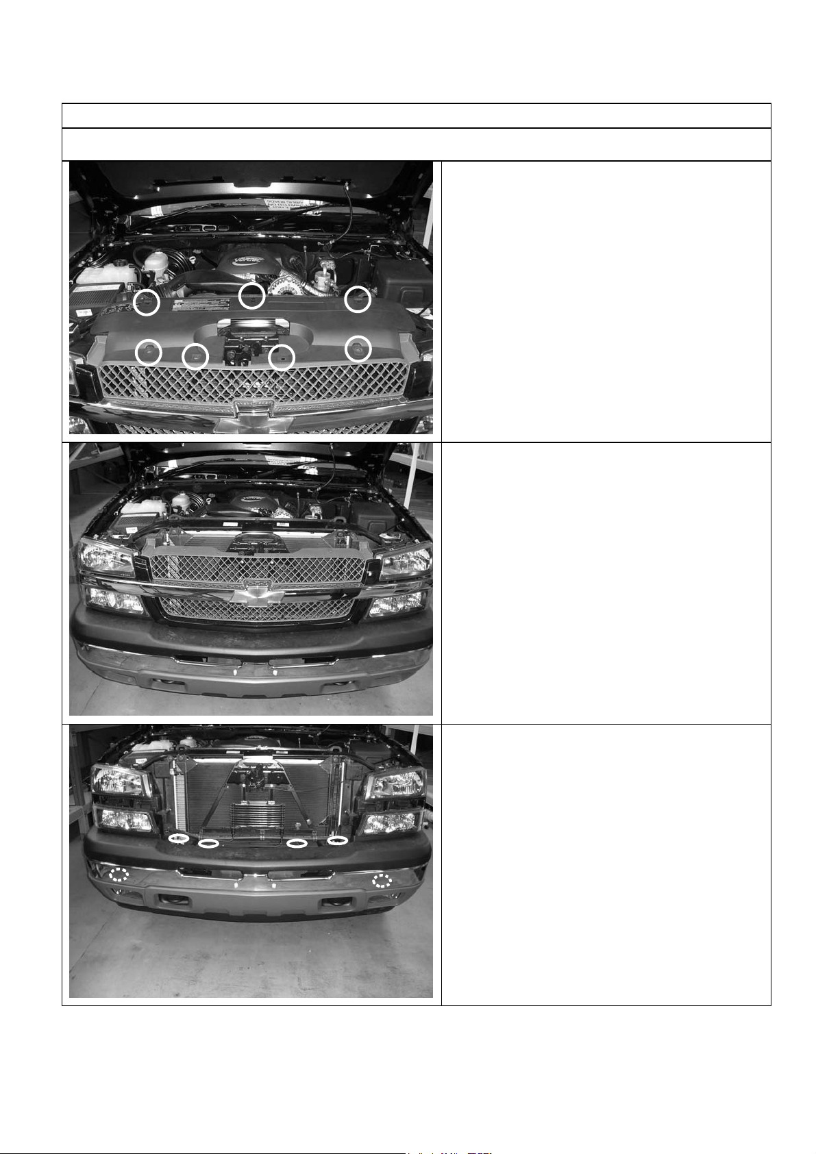
ASSEMBLY SEQUENCE FOR WINCH BUMPER.
1. FITTING MOUNTING BRACKETS
1.1 Remove the plastic shroud above the
radiator as shown, by releasing plastic
clips
1.2 To remove the grille, carefully push the
retainer spring clips back out in four
places behind grille. Pull outer bar from
between headlights forward to release
from clip into end of guard. NOTE: It may
be necessary to remove top headlights to
gain access to these clips if you cannot
release them easily.
1.3 Remove bumper by undoing four bolts
from above and behind bumper then two
bolts securing bumper to wing support
braces from under and behind forward of
wheel arch area.
11/10/05 Page 4 of 14 3783176
Page 5
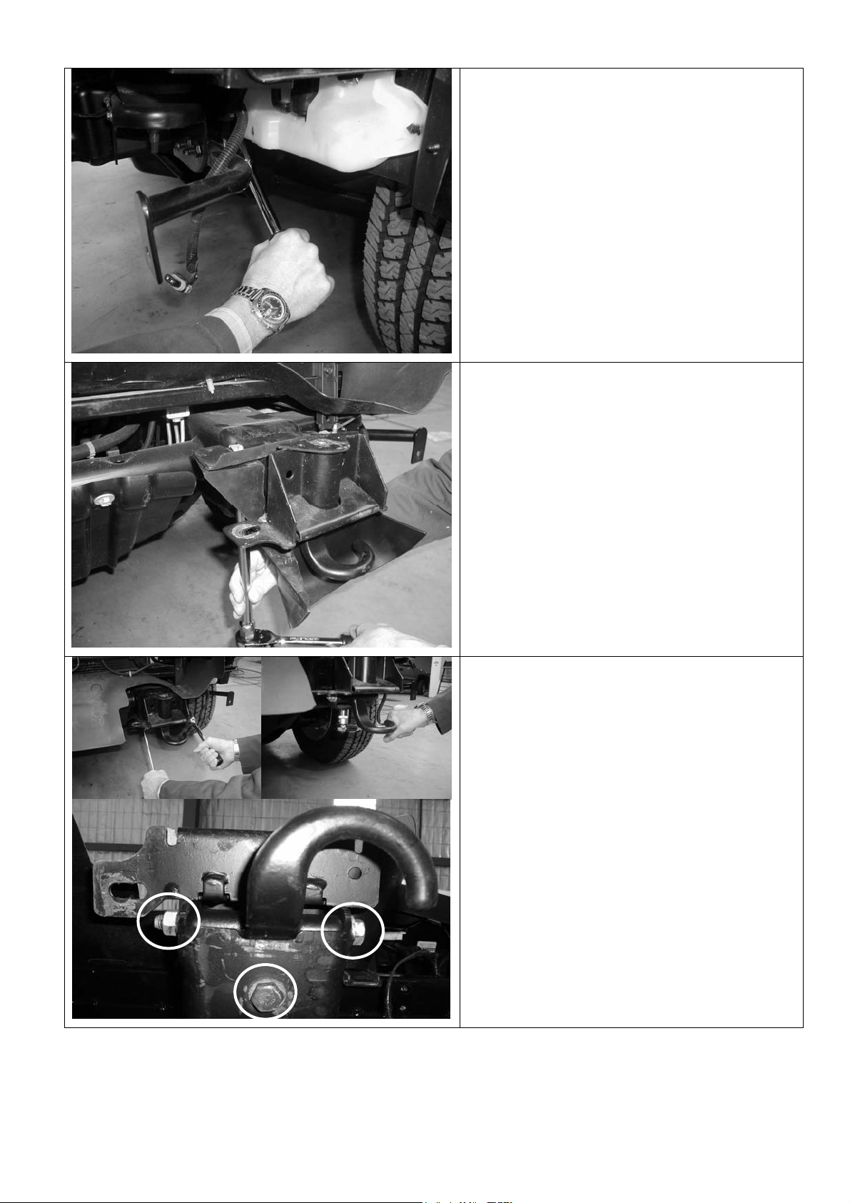
1.4 Remove stabilizer arms both sides
1.5 Remove plastic shrouds around chassis
1.6 Remove tow hooks
11/10/05 Page 5 of 14 3783176
Page 6
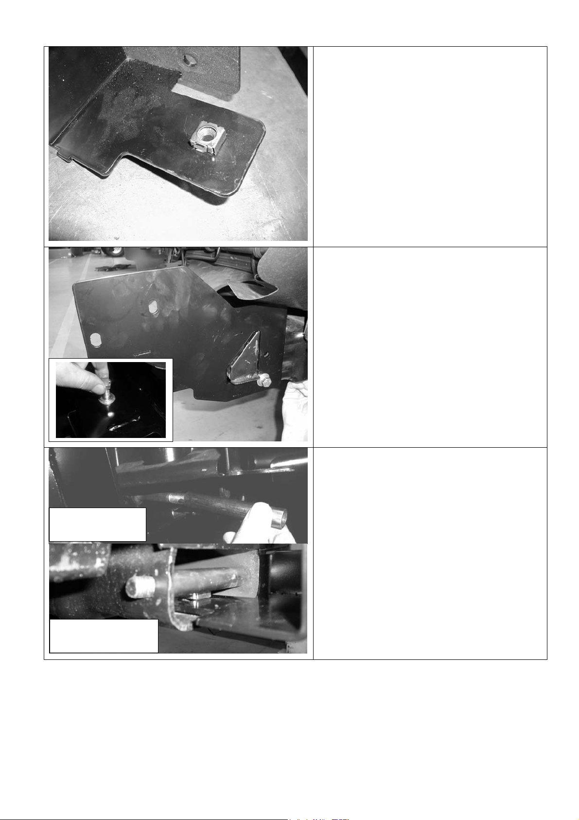
1.7 Fit cage nuts to bracket tangs as shown
1.8 Position the mount brackets as shown on
the ends of the chassis rails (LHS shown).
Loosely fit an M12 bolt and washer set to
top bolt position and lower position as
shown finger tight only.
Inserting sleeve
Sleeve in position
1.9 Partly withdraw M12 x 150 bolt and fit
crush sleeve over bolt body inside chassis
as shown. Fit flat and spring washers, and
nut. Do not tighten.
11/10/05 Page 6 of 14 3783176
Page 7
1.10 Fit M12 cage nuts to both bent plates, 1 x
LH and 1 x RH as assemblies are
opposite for each side of vehicle. Insert
nut assembly through large hole in
underside of chassis and up to meet
vacant hole above long bolt. Insert M12
bolt and washer set, do up finger tight.
1.14 Check that brackets are parallel to each
other, if not adjust. When parallel then
tighten all bolts (nominal outside
dimension across brackets is 898mm).
Fit grille and shroud back into
position.
11/10/05 Page 7 of 14 3783176
Page 8
2. PREPARING BULL BAR FOR FITTING
2.1 Remove lights from cartons and then
remove screws and speed nuts from each
light. These fasteners are not to be reused
– new screws are supplied in the fitting kit.
2.2 Insert nylon nuts into square holes in light
brackets inside wing area
2.3 Fit lights using screws supplied in fitting
kit, taking note of RH and LH light bodies,
they are different and must be placed on
the correct side of bull bar.
2.4 Fit large eyebolt nut into the plate on the
inside of the bar.
11/10/05 Page 8 of 14 3783176
Page 9
2.5 Screw in the eyebolt using the large
washer. Eyebolt can be positioned to sit
vertically by rotating the large nut to the
correct position.
NOTE: EYEBOLTS SHOULD BE REMOVED
FOR SAFETY REASONS WHEN
TRAVELLING ON PUBLIC ROADS.
2.6 When the large nut is in its final position,
secure with the nut retaining bracket using
an M6 bolt, washer and flange nut.
2.7 Secure the number plate bracket using M6
bolts, flat washers and flange nuts. Attach
the longer flange to the bullbar and the
shorter flange to the number plate.
2.8 Fit the M8 cage nuts to the square holes in
the wing brace on the LHS (washer bottle
side) of the bull bar. The body of the cage
nuts are to be on the inside of the brace.
These nuts are to be used to fasten the
washer bottle protection arm to the bull bar.
11/10/05 Page 9 of 14 3783176
Page 10
3. IF FITTING WINCH
3.1 From the factory the winch handle should
be in the position as shown.
Remove cable retaining band and position
cable loop so it will go through roller
fairlead when it is placed in bull bar.
3.2 Fit control box to pan:
• For 9500-12000lb winches, use universal
control box bracket supplied, attaching to
rear of control box mount studs.
• Slide bracket flange under pan and align
with mount slots.
• Fasten in position with 2 x M10 cap
screws, black washers and flange nuts.
• For 15000lb winches, use Warn supplied
control box bracket, attaching to rear of
control box mount studs.
• Slide bracket flange under pan and align
with mount slots.
• Fasten in position with 2 x M10 cap
screws, black washers and flange nuts.
11/10/05 Page 10 of 14 3783176
Page 11
• For 16500lb winches, apply Sikaflex (or
similar product) to rear of control box trim
plate from fitting kit (note orientation critical
to suit final position with control box profile
in pan opening).
• Position trim plate on top of pan centrally
about control box opening and line up with
mount slots.
• Fasten in position with 2 x M10 cap screws
and flange nuts from fitting kit.
3.3 On some models, the roller fair lead must
be drilled prior to fitment.
Mark out as shown and using a 13.0 mm
drill bit, drill two holes as shown in
diagram.
3.4 Viewed from front of vehicle the winch
clutch (handle) must be positioned on the
LH side (same side as smaller square
access hole in pan). Cable must spool
from the bottom of winch. Draw off
enough cable so cable crimp can be
pulled through roller fairlead.
Hint: If crimp is too large to fit through, remove
a circlip from a horizontal roller, partially
remove the shaft so roller gap is increased and
feed cable and crimp through. Refit shaft and
circlip.
Bolt winch in position with the roller fair lead in
place.
Hint: To increase access to mount bolts in
front of roller fairlead, remove circlips from
bottom of each vertical roller shaft, push shaft
up so roller can be dislodged sideways. Do up
bolts in fairlead and winch, then refit circlip.
Connect the winch control box cables to the
winch motor. Refer to the Warn handbook for
additional information. Connect the long winch
+ & - cables to the vehicle after
installed. Refer to the Warn winch manual
for vehicle wiring instructions.
the bar is
11/10/05 Page 11 of 14 3783176
Page 12
3.5
Fitting with winch, number plate above RFL
Fitting without winch, number plate covers RFL
opening
Fitting number plate – with winch
Bolt number plate to the bracket with the
M6 X 16mm bolts and M6 flange nuts
through the lower holes of the number
plate.
If not fitting winch.
Bolt the number plate through the top
holes using M6 X 16mm bolts and M6
flange nuts.
3.6 If not fitting winch cont.
Wrap rubber extrusion around winch
cover.
Place washers over the winch cover fixing
holes located on the top middle face of the
winch bumper.
Place the winch cover on top of the winch
bumper inline with the mount holes.
Bolt together using the M6 button head
stainless steel screws and M6 nuts.
11/10/05 Page 12 of 14 3783176
Page 13
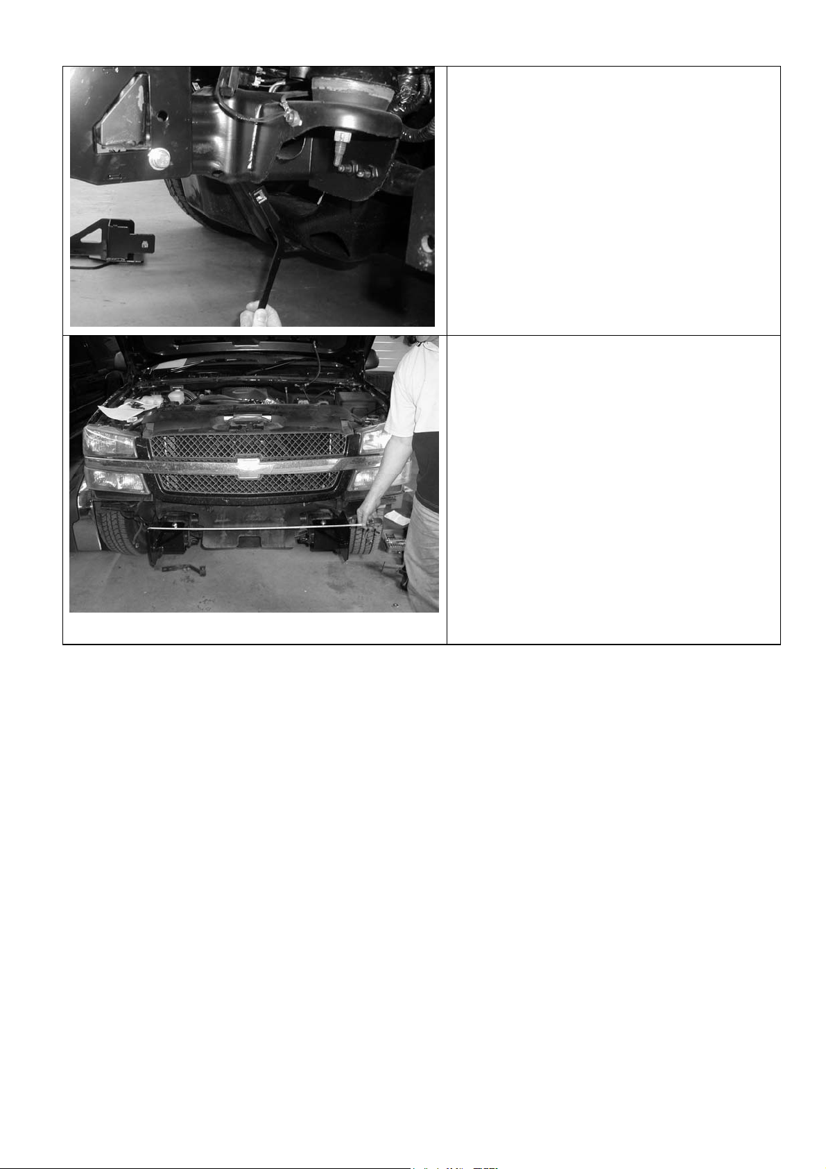
4. FITTING BULL BAR TO VEHICLE
4.1 Using two people, three if winch fitted,
position the bar assembly on the vehicle
mounts.
Bolt the bar to the mounts using M12
bolts, large flat washers and spring
washers. Align the bar to the profile of the
guards, grille and light profile and tighten
all bolts.
Using the M10 pilot holes in mount
brackets, drill pinning hole through
uprights on bull bar. Fit M10 screw,
washer set and flange nut and do up tight.
4.2 Trim excess plastic inner guard molding to
meet lower profile of bull bar wing. Note
the position of water bottle on LHS of
vehicle and trim neatly around it.
4.3 Fit washer bottle protection frame to
lower mounts where original bumper
stabiliser arms were located using 2 x
M10 x 30 bolt and washer sets. Fit off
the upper bracket to inner wing area of
bull bar as shown using M8 x 25 bolts
and washer sets.
NOTE: The 2 x M8 cage nuts should be in
place from step 2.7.
4.4 Fit inner guard plates to ends of bull bar
wings and fasten with M6 black screws
and washers.
11/10/05 Page 13 of 14 3783176
Page 14
4.5 If fitting with winch
With the winch cable through the roller fair
lead. Mount the hook to the end of the
cable.
4.6 Wire up the indicator and clearance lamp
assemblies. Use scotch locks to splice
cables to existing indicator and clearance
lamp wiring and cable tie securely.
If fog lights are to be installed, mount
positions are on lower pan area between
winch opening and high lift jack position.
Refer to the Warn winch manual for
vehicle wiring instructions.
Ensure that electrical cables are installed
well clear of sharp, hot or moving objects.
Secure the winch cables to the vehicle
and winch bumper with the supplied cable
ties.
11/10/05 Page 14 of 14 3783176
Page 15
ARB COMBINATION WINCH, NON-WINCH BULL BAR TO SUIT
CHEVROLET SILVERADO 03 ON 1500 MODELS.
PRODUCT No. 3462020, WITH FITTING KIT 3562040
WARNING
FOR VEHICLES EQUIPPED WITH SRS AIRBAG
WHEN INSTALLED IN ACCORDANCE WITH THESE INSTRUCTIONS, THE FRONT
PROTECTION BAR DOES NOT AFFECT OPERATION OF THE SRS AIRBAG.
TAKE NOTE OF THE FOLLOWING:
• THIS PRODUCT MUST BE INSTALLED EXACTLY AS PER THESE
INSTRUCTIONS USING ONLY THE HARDWARE SUPPLIED.
• IN THE EVENT OF DAMAGE TO ANY BULL BAR COMPONENT,
CONTACT YOUR NEAREST AUTHORISED ARB STOCKIST. REPAIRS OR
MODIFICATIONS TO THE IMPACT ABSORPTION SYSTEM MUST NOT BE
ATTEMPED.
• DO NOT USE THIS PRODUCT FOR ANY VEHICLE MAKE OR MODEL,
OTHER THAN THOSE SPECIFIED BY ARB.
• DO NOT REMOVE LABELS FROM THIS BULL BAR.
• THIS PRODUCT OR ITS FIXING MUST NOT BE MODIFIED IN ANY WAY.
Note :
• This bull bar is suitable for Warn 9,500-16,500lb winches.
• Fog light provisions are in lower pan area of bull bar. IPF840FYS lights
are suitable for this location.
Tools Required
Metric Spanner and Socket set Allen key set
Phillips head screwdriver Dia 15/64”, 10.0 and 12.0mm drill bits
Electric drill 13mm chuck Sikaflex 227 adhesive, black color
11/10/05 Page 1 of 14 3783176
If you have any queries regarding the installation of this product please contact the distributor from whom it was purchased, or alternatively the ARB office in your state.
WA: (08) 9244 3553 NSW: (02) 9821 3633 ACT: (02) 6280 7475 SA: (08) 8244 5001 QLD: (07) 3872 3872 NT: (08) 8947 2262 TAS: (03) 6331 4190
Head Office – ARB Corporation Ltd VIC: 42-44 Garden Street, Kilsyth, Victoria, 3137 Tel: (03) 9761 6622 Fax: (03) 9761 6807
Page 16

USE PART No QTY DESCRIPTION
MOUNT BRACKETS TO VEHICLE 3756785L 1 BRACKET BAR MOUNT LHS
3756785R 1 BRACKET BAR MOUNT RHS
3199796 2 PLATE CAGE NUT
4581049 10 M12 WASHER FLAT
4581050 8 M12 WASHER SPRING
6151255 6 BOLT M12 X 40
6151244 2 BOLT M12X150
6151189 2 NUT M12x1.75
6151305 4 NUT M12 CAGE SUIT 4MM
5811037 2 SLEEVE
WINCH 180302 8 CABLE TIE
TOW HOOK RELOCATION 6151365 2 EYEBOLT M24 2.5 SWL
6151361 2 NUT M24 GR8 ZP
3756765 2 BRACKET NUT RETAINING
4581300 2 WASHER M24 EYEBOLT
6151046 2 WASHER M6
6151017 2 BOLT M6 X 16mm
6151128 2 NUT FLANGE M6
CONTROL BOX FITTMENT 4581291 2 WASHER M10 BZ
6151321 2 NUT FLANGED
6151364 2 SCREW CAP M10X30 ZP
3756775 1 BRACKET STD CONTROL BOX IN PAN
3199790 1 TRIM PLATE FOR 16500LB CONTROL
NUMBER PLATE FITTMENT 6151017 4 BOLT M6 X 16mm
6151128 4 NUT FLANGE M6
6151046 4 WASHER M6
3751384 1 BRACKET NO.PLATE
WINCH COVER FITTMENT 6151128 2 NUT FLANGE M6
6151256 2 SCREW M6 S/STEEL BUTTON HEAD
6151046 2 WASHER M6
6191013 1 EXTRUSION WINCH COVER @ 1757
6522048 1 PANEL WINCH COVER
WASHER BOTTLE PROTECTION 6131349 1 FRAME ASSY WASHR BOTTLE PROT
6151303 2 NUT CAGED M8 SUIT 1.6-3.2
6151022 2 BOLT M8X25
4581044 2 WASHER FLAT M8
4581046 2 WASHER SPR M8
6151232 2 BOLT M10X30
4581040 2 WASHER FLAT M10
4581048 2 WASHER SPR M10
11/10/05 Page 2 of 14 3783176
Page 17

BAR TO MOUNT ASSEMBLY 6151255 6 BOLT M12 X 40mm
4581050 6 WASHER SPRING M12
4581049 12 WASHER FLAT M12
4581048 2 WASHER SPRING M10
6151321 2 NUT M10 FLANGED
6151232 2 BOLT M10 X 30mm
4581040 2 WASHER FLAT 3/8”
6151189 6 NUT M12x1.75
INDICATOR ASSY 6821151R 1 INDICATOR ASSY RHS
6821151L 1 INDICATOR ASSY LHS
6151308 4 SCREW SELF TAPPING
6821116 4 NUT NYLON PLUG
6821152 2 LOOM
180701 6 SCOTCH LOCKS
180302 4 CABLE TIE
INNER GUARD RETAINER 3199787R 1 PLATE INNER GUARD
3199787L 1 PLATE INNER GUARD
6151128 4 NUT FLANGE M6
6151213 4 SCREW M6X20 BZ
4581082 4 WASHER M6X20 BZ
NOTE: Shipping brackets connecting
bull bar to pallet and associated
fasteners are not intended to be reused
in fitted bar assembly.
11/10/05 Page 3 of 14 3783176
Page 18

ASSEMBLY SEQUENCE FOR WINCH BUMPER.
1. FITTING MOUNTING BRACKETS
1.1 Remove the plastic shroud above the
radiator as shown, by releasing plastic
clips
1.2 To remove the grille, carefully push the
retainer spring clips back out in four
places behind grille. Pull outer bar from
between headlights forward to release
from clip into end of guard. NOTE: It may
be necessary to remove top headlights to
gain access to these clips if you cannot
release them easily.
1.3 Remove bumper by undoing four bolts
from above and behind bumper then two
bolts securing bumper to wing support
braces from under and behind forward of
wheel arch area.
11/10/05 Page 4 of 14 3783176
Page 19

1.4 Remove stabilizer arms both sides
1.5 Remove plastic shrouds around chassis
1.6 Remove tow hooks
11/10/05 Page 5 of 14 3783176
Page 20

1.7 Fit cage nuts to bracket tangs as shown
1.8 Position the mount brackets as shown on
the ends of the chassis rails (LHS shown).
Loosely fit an M12 bolt and washer set to
top bolt position and lower position as
shown finger tight only.
Inserting sleeve
Sleeve in position
1.9 Partly withdraw M12 x 150 bolt and fit
crush sleeve over bolt body inside chassis
as shown. Fit flat and spring washers, and
nut. Do not tighten.
11/10/05 Page 6 of 14 3783176
Page 21

1.10 Fit M12 cage nuts to both bent plates, 1 x
LH and 1 x RH as assemblies are
opposite for each side of vehicle. Insert
nut assembly through large hole in
underside of chassis and up to meet
vacant hole above long bolt. Insert M12
bolt and washer set, do up finger tight.
1.14 Check that brackets are parallel to each
other, if not adjust. When parallel then
tighten all bolts (nominal outside
dimension across brackets is 898mm).
Fit grille and shroud back into
position.
11/10/05 Page 7 of 14 3783176
Page 22

2. PREPARING BULL BAR FOR FITTING
2.1 Remove lights from cartons and then
remove screws and speed nuts from each
light. These fasteners are not to be reused
– new screws are supplied in the fitting kit.
2.2 Insert nylon nuts into square holes in light
brackets inside wing area
2.3 Fit lights using screws supplied in fitting
kit, taking note of RH and LH light bodies,
they are different and must be placed on
the correct side of bull bar.
2.4 Fit large eyebolt nut into the plate on the
inside of the bar.
11/10/05 Page 8 of 14 3783176
Page 23

2.5 Screw in the eyebolt using the large
washer. Eyebolt can be positioned to sit
vertically by rotating the large nut to the
correct position.
NOTE: EYEBOLTS SHOULD BE REMOVED
FOR SAFETY REASONS WHEN
TRAVELLING ON PUBLIC ROADS.
2.6 When the large nut is in its final position,
secure with the nut retaining bracket using
an M6 bolt, washer and flange nut.
2.7 Secure the number plate bracket using M6
bolts, flat washers and flange nuts. Attach
the longer flange to the bullbar and the
shorter flange to the number plate.
2.8 Fit the M8 cage nuts to the square holes in
the wing brace on the LHS (washer bottle
side) of the bull bar. The body of the cage
nuts are to be on the inside of the brace.
These nuts are to be used to fasten the
washer bottle protection arm to the bull bar.
11/10/05 Page 9 of 14 3783176
Page 24

3. IF FITTING WINCH
3.1 From the factory the winch handle should
be in the position as shown.
Remove cable retaining band and position
cable loop so it will go through roller
fairlead when it is placed in bull bar.
3.2 Fit control box to pan:
• For 9500-12000lb winches, use universal
control box bracket supplied, attaching to
rear of control box mount studs.
• Slide bracket flange under pan and align
with mount slots.
• Fasten in position with 2 x M10 cap
screws, black washers and flange nuts.
• For 15000lb winches, use Warn supplied
control box bracket, attaching to rear of
control box mount studs.
• Slide bracket flange under pan and align
with mount slots.
• Fasten in position with 2 x M10 cap
screws, black washers and flange nuts.
11/10/05 Page 10 of 14 3783176
Page 25

• For 16500lb winches, apply Sikaflex (or
similar product) to rear of control box trim
plate from fitting kit (note orientation critical
to suit final position with control box profile
in pan opening).
• Position trim plate on top of pan centrally
about control box opening and line up with
mount slots.
• Fasten in position with 2 x M10 cap screws
and flange nuts from fitting kit.
3.3 On some models, the roller fair lead must
be drilled prior to fitment.
Mark out as shown and using a 13.0 mm
drill bit, drill two holes as shown in
diagram.
3.4 Viewed from front of vehicle the winch
clutch (handle) must be positioned on the
LH side (same side as smaller square
access hole in pan). Cable must spool
from the bottom of winch. Draw off
enough cable so cable crimp can be
pulled through roller fairlead.
Hint: If crimp is too large to fit through, remove
a circlip from a horizontal roller, partially
remove the shaft so roller gap is increased and
feed cable and crimp through. Refit shaft and
circlip.
Bolt winch in position with the roller fair lead in
place.
Hint: To increase access to mount bolts in
front of roller fairlead, remove circlips from
bottom of each vertical roller shaft, push shaft
up so roller can be dislodged sideways. Do up
bolts in fairlead and winch, then refit circlip.
Connect the winch control box cables to the
winch motor. Refer to the Warn handbook for
additional information. Connect the long winch
+ & - cables to the vehicle after
installed. Refer to the Warn winch manual
for vehicle wiring instructions.
the bar is
11/10/05 Page 11 of 14 3783176
Page 26

3.5
Fitting with winch, number plate above RFL
Fitting without winch, number plate covers RFL
opening
Fitting number plate – with winch
Bolt number plate to the bracket with the
M6 X 16mm bolts and M6 flange nuts
through the lower holes of the number
plate.
If not fitting winch.
Bolt the number plate through the top
holes using M6 X 16mm bolts and M6
flange nuts.
3.6 If not fitting winch cont.
Wrap rubber extrusion around winch
cover.
Place washers over the winch cover fixing
holes located on the top middle face of the
winch bumper.
Place the winch cover on top of the winch
bumper inline with the mount holes.
Bolt together using the M6 button head
stainless steel screws and M6 nuts.
11/10/05 Page 12 of 14 3783176
Page 27

4. FITTING BULL BAR TO VEHICLE
4.1 Using two people, three if winch fitted,
position the bar assembly on the vehicle
mounts.
Bolt the bar to the mounts using M12
bolts, large flat washers and spring
washers. Align the bar to the profile of the
guards, grille and light profile and tighten
all bolts.
Using the M10 pilot holes in mount
brackets, drill pinning hole through
uprights on bull bar. Fit M10 screw,
washer set and flange nut and do up tight.
4.2 Trim excess plastic inner guard molding to
meet lower profile of bull bar wing. Note
the position of water bottle on LHS of
vehicle and trim neatly around it.
4.3 Fit washer bottle protection frame to
lower mounts where original bumper
stabiliser arms were located using 2 x
M10 x 30 bolt and washer sets. Fit off
the upper bracket to inner wing area of
bull bar as shown using M8 x 25 bolts
and washer sets.
NOTE: The 2 x M8 cage nuts should be in
place from step 2.7.
4.4 Fit inner guard plates to ends of bull bar
wings and fasten with M6 black screws
and washers.
11/10/05 Page 13 of 14 3783176
Page 28

4.5 If fitting with winch
With the winch cable through the roller fair
lead. Mount the hook to the end of the
cable.
4.6 Wire up the indicator and clearance lamp
assemblies. Use scotch locks to splice
cables to existing indicator and clearance
lamp wiring and cable tie securely.
If fog lights are to be installed, mount
positions are on lower pan area between
winch opening and high lift jack position.
Refer to the Warn winch manual for
vehicle wiring instructions.
Ensure that electrical cables are installed
well clear of sharp, hot or moving objects.
Secure the winch cables to the vehicle
and winch bumper with the supplied cable
ties.
11/10/05 Page 14 of 14 3783176
Page 29

ARB COMBINATION WINCH, NON-WINCH BULL BAR TO SUIT
CHEVROLET SILVERADO 03 ON 1500HD-2500 MODELS.
PRODUCT No. 3462020, WITH FITTING KIT 3562050
WARNING
FOR VEHICLES EQUIPPED WITH SRS AIRBAG
WHEN INSTALLED IN ACCORDANCE WITH THESE INSTRUCTIONS, THE FRONT
PROTECTION BAR DOES NOT AFFECT OPERATION OF THE SRS AIRBAG.
TAKE NOTE OF THE FOLLOWING:
• THIS PRODUCT MUST BE INSTALLED EXACTLY AS PER THESE
INSTRUCTIONS USING ONLY THE HARDWARE SUPPLIED.
• IN THE EVENT OF DAMAGE TO ANY BULL BAR COMPONENT,
CONTACT YOUR NEAREST AUTHORISED ARB STOCKIST. REPAIRS OR
MODIFICATIONS TO THE IMPACT ABSORPTION SYSTEM MUST NOT BE
ATTEMPED.
• DO NOT USE THIS PRODUCT FOR ANY VEHICLE MAKE OR MODEL,
OTHER THAN THOSE SPECIFIED BY ARB.
• DO NOT REMOVE LABELS FROM THIS BULL BAR.
• THIS PRODUCT OR ITS FIXING MUST NOT BE MODIFIED IN ANY WAY.
Note :
• This bull bar is suitable for Warn 9,500-16,500lb winches.
• Fog light provisions are in lower pan area of bull bar. IPF840FYS lights
are suitable for this location.
Tools Required
Metric Spanner and Socket set Allen key set
Phillips head screwdriver Dia 15/64”, 10.0 and 12.0mm drill bits
Electric drill 13mm chuck Sikaflex 227 adhesive, black color
11/10/05 Page 1 of 14 3783177
If you have any queries regarding the installation of this product please contact the distributor from whom it was purchased, or alternatively the ARB office in your state.
WA: (08) 9244 3553 NSW: (02) 9821 3633 ACT: (02) 6280 7475 SA: (08) 8244 5001 QLD: (07) 3872 3872 NT: (08) 8947 2262 TAS: (03) 6331 4190
Head Office – ARB Corporation Ltd VIC: 42-44 Garden Street, Kilsyth, Victoria, 3137 Tel: (03) 9761 6622 Fax: (03) 9761 6807
Page 30

USE PART No QTY DESCRIPTION
MOUNT BRACKETS TO VEHICLE 3756786L 1 BRACKET BAR MOUNT LHS
3756786R 1 BRACKET BAR MOUNT RHS
4581060 2 WASHER 13X30X3
4581049 12 M12 WASHER FLAT
4581050 8 M12 WASHER SPRING
6151255 8 BOLT M12 X 40
6151189 6 NUT M12x1.75
5848316 2 PACKER
WINCH 180302 8 CABLE TIE
TOW HOOK RELOCATION 6151365 2 EYEBOLT M24 2.5 SWL
6151361 2 NUT M24 GR8 ZP
3756765 2 BRACKET NUT RETAINING
4581300 2 WASHER M24 EYEBOLT
6151046 2 WASHER M6
6151017 2 BOLT M6 X 16mm
6151128 2 NUT FLANGE M6
CONTROL BOX FITTMENT 4581291 2 WASHER M10 BZ
6151321 2 NUT FLANGED
6151364 2 SCREW CAP M10X30 ZP
3756775 1 BRACKET STD CONTROL BOX IN PAN
3199790 1 TRIM PLATE FOR 16500LB CONTROL
NUMBER PLATE FITTMENT 6151017 4 BOLT M6 X 16mm
6151128 4 NUT FLANGE M6
6151046 4 WASHER M6
3751384 1 BRACKET NO.PLATE
WINCH COVER FITTMENT 6151128 2 NUT FLANGE M6
6151256 2 SCREW M6 S/STEEL BUTTON HEAD
6151046 2 WASHER M6
6191013 1 EXTRUSION WINCH COVER @ 1757
6522048 1 PANEL WINCH COVER
WASHER BOTTLE PROTECTION 6131349 1 FRAME ASSY WASHR BOTTLE PROT
6151303 2 NUT CAGED M8 SUIT 1.6-3.2
6151022 2 BOLT M8X25
4581044 2 WASHER FLAT M8
4581046 2 WASHER SPR M8
6151232 2 BOLT M10X30
4581040 2 WASHER FLAT M10
4581048 2 WASHER SPR M10
11/10/05 Page 2 of 14 3783177
Page 31

BAR TO MOUNT ASSEMBLY 6151255 6 BOLT M12 X 40mm
4581050 6 WASHER SPRING M12
4581049 12 WASHER FLAT M12
4581048 2 WASHER SPRING M10
6151321 2 NUT M10 FLANGED
6151232 2 BOLT M10 X 30mm
4581040 2 WASHER FLAT 3/8”
6151189 6 NUT M12x1.75
INDICATOR ASSY 6821151R 1 INDICATOR ASSY RHS
6821151L 1 INDICATOR ASSY LHS
6151308 4 SCREW SELF TAPPING
6821116 4 NUT NYLON PLUG
6821152 2 LOOM
180701 6 SCOTCH LOCKS
180302 4 CABLE TIE
INNER GUARD RETAINER 3199787R 1 PLATE INNER GUARD
3199787L 1 PLATE INNER GUARD
6151128 4 NUT FLANGE M6
6151213 4 SCREW M6X20 BZ
4581082 4 WASHER M6X20 BZ
NOTE: Shipping brackets connecting
bull bar to pallet and associated
fasteners are not intended to be reused
in fitted bar assembly.
11/10/05 Page 3 of 14 3783177
Page 32

ASSEMBLY SEQUENCE FOR WINCH BUMPER.
1. FITTING MOUNTING BRACKETS
1.1 Remove plastic shroud above radiator as
shown, by releasing plastic clips
1.2 To remove the grille, carefully push the
retainer spring clips back out in four
places behind grille. Pull outer bar from
between headlights forward to release
from clip into end of guard. NOTE: It may
be necessary to remove top headlights to
gain access to these clips if you cannot
release them easily.
1.3 Remove bumper by undoing four bolts
from above and behind bumper then two
bolts securing bumper to wing support
braces from under and behind forward of
wheel arch area.
11/10/05 Page 4 of 14 3783177
Page 33

1.4 Remove and replace tow hooks on
opposite chassis sides. Note, the hole
underneath the chassis may need to be
elongated to allow the bolt to fit into the
rear underside position. Leave the outer
bolt off.
1.5 Fit the mount brackets as shown, to the
end of the chassis rails, top M12 bolt and
washer set as shown finger tight only.
1.6 Slide in ‘L’ shaped packer oriented as
shown
1.7 Fit M12 bolt, spring washer and Dia
13.0x30x3 large washer into tow hook
thread, insert M12 bolt and washer set in
pinning hole to line up packer hole.
Tighten up lower bolt.
Remove loose bolt from pinning hole and
drill through using Dia12.0 drill. Then
insert and do up M12 bolt set.
11/10/05 Page 5 of 14 3783177
Page 34

1.8 Drill pinning hole in top position as shown
then insert and do up M12 bolt set.
1.9 Tighten up all bolts
1.10 Check that tops of brackets are
horizontal and that brackets are parallel to
each other. If not release bolts and make
necessary adjustments.
Refit grille and shroud.
11/10/05 Page 6 of 14 3783177
Page 35

2. PREPARING BULL BAR FOR FITTING
2.1 Remove lights from cartons and then
remove screws and speed nuts from each
light. These fasteners are not to be reused
– new screws are supplied in the fitting kit.
2.2 Insert nylon nuts into square holes in light
brackets inside wing area
2.3 Fit lights using screws supplied in fitting
kit, taking note of RH and LH light bodies,
they are different and must be placed on
the correct side of bull bar.
11/10/05 Page 7 of 14 3783177
Page 36

2.4 Fit large eyebolt nut into the plate on the
inside of the bar.
2.5 Screw in the eyebolt using the large
washer. Eyebolt can be positioned to sit
vertically by rotating the large nut to the
correct position.
NOTE: EYEBOLTS SHOULD BE REMOVED
FOR SAFETY REASONS WHEN
TRAVELLING ON PUBLIC ROADS.
2.6 When the large nut is in its final position,
secure with the nut retaining bracket using
an M6 bolt, washer and flange nut.
2.7 Secure the number plate bracket using M6
bolts, flat washers and flange nuts. Attach
the longer side to the bullbar and the
shorter side to the number plate.
11/10/05 Page 8 of 14 3783177
Page 37

3. IF FITTING WINCH
3.1 From the factory the winch handle should
be in the position as shown.
Remove cable retaining band and position
cable loop so it will go through roller
fairlead when it is placed in bull bar.
3.2 Fit control box to pan:
• For 9500-12000lb winches, use universal
control box bracket supplied, attaching to
rear of control box mount studs.
• Slide bracket flange under pan and align
with mount slots.
• Fasten in position with 2 x M10 cap
screws, black washers and flange nuts.
• For 15000lb winches, use Warn supplied
control box bracket, attaching to rear of
control box mount studs.
• Slide bracket flange under pan and align
with mount slots.
• Fasten in position with 2 x M10 cap
screws, black washers and flange nuts.
11/10/05 Page 9 of 14 3783177
Page 38

• For 16500lb winches, apply Sikaflex (or
similar product) to rear of control box trim
plate from fitting kit (note orientation critical
to suit final position with control box profile
in pan opening).
• Position trim plate on top of pan centrally
about control box opening and line up with
mount slots.
• Fasten in position with 2 x M10 cap screws
and flange nuts from fitting kit.
3.3 On some models, the roller fair lead must
be drilled prior to fitment.
Mark out as shown and using a 13.0 mm
drill bit, drill two holes as shown in
diagram.
3.4 Viewed from front of vehicle the winch
clutch (handle) must be positioned on the
LH side (same side as smaller square
access hole in pan). Cable must spool
from the bottom of winch. Draw off
enough cable so cable crimp can be
pulled through roller fairlead.
Hint: If crimp is too large to fit through, remove
a circlip from a horizontal roller, partially
remove the shaft so roller gap is increased
and feed cable and crimp through. Refit shaft
and circlip.
Bolt winch in position with the roller fair lead in
place.
Hint: To increase access to mount bolts in
front of roller fairlead, remove circlips from
bottom of each vertical roller shaft, push shaft
up so roller can be dislodged sideways. Do up
bolts in fairlead and winch, then refit circlip.
Connect the winch control box cables to the
winch motor. Refer to the Warn handbook for
additional information. Connect the long winch
+ & - cables to the vehicle after the bar is
installed. Refer to the Warn winch manual
for vehicle wiring instructions.
11/10/05 Page 10 of 14 3783177
Page 39

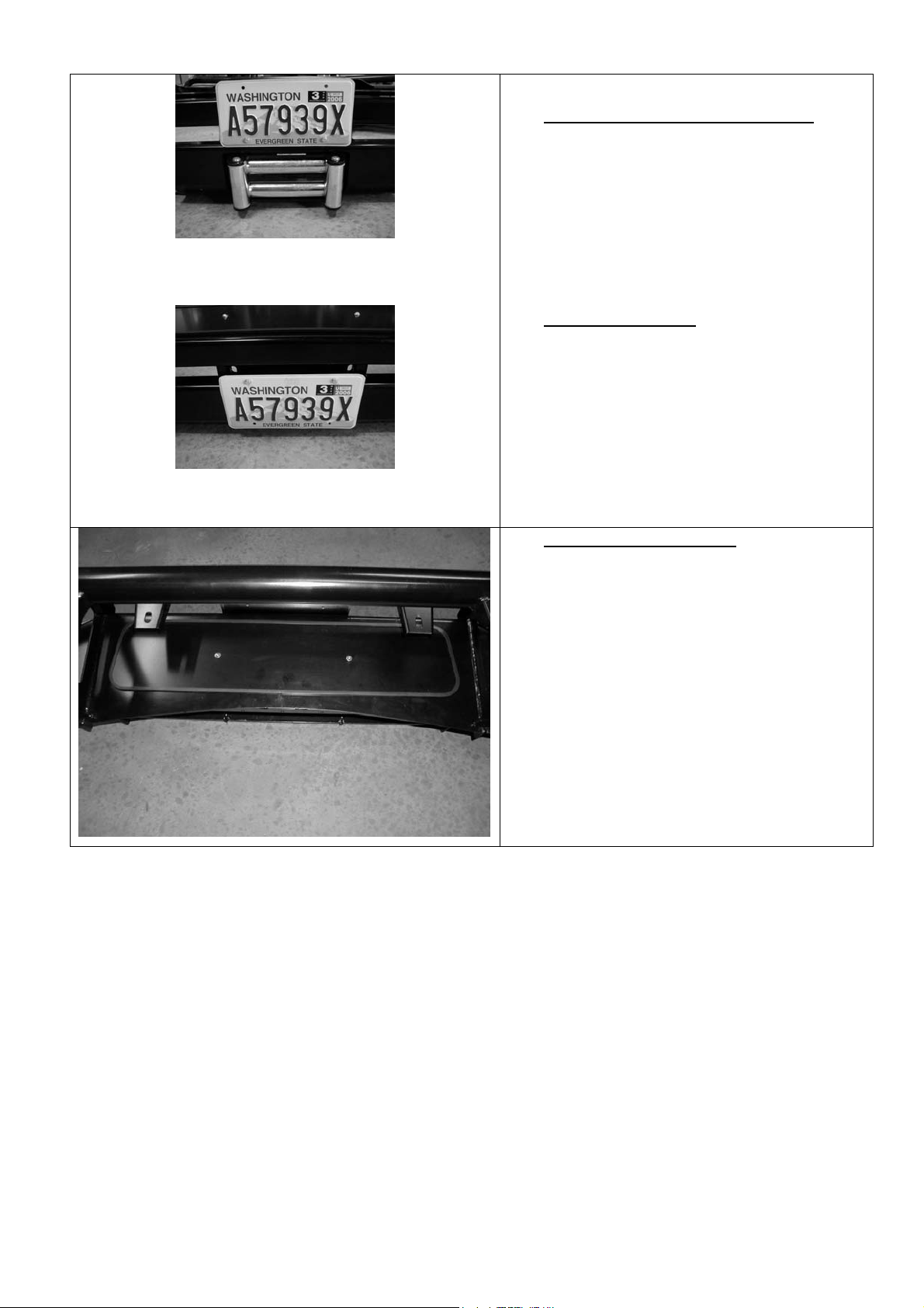
3.5
Fitting with winch, number plate above RFL
Fitting without winch, number plate covers RFL
opening
Fitting number plate – with winch
Bolt number plate to the bracket with the
M6 X 16mm bolts and M6 flange nuts
through the lower holes of the number
plate.
If not fitting winch.
Bolt the number plate through the top
holes using M6 X 16mm bolts and M6
flange nuts.
3.6 If not fitting winch cont.
View from above, rear of bull bar
Wrap rubber extrusion around winch
cover.
Place washers over the winch cover fixing
holes located on the top middle face of the
winch bumper.
Place the winch cover on top of the winch
bumper inline with the mount holes.
Bolt together using the M6 button head
stainless steel screws and M6 nuts.
3.7 Fit the M8 cage nuts to the square holes
in the wing brace on the LHS (washer
bottle side) of the bull bar. The body of
the cage nuts are to be on the inside of
the brace. These nuts are to be used to
fasten the washer bottle protection arm to
the bull bar.
11/10/05 Page 11 of 14 3783177
Page 40

4. FITTING BULL BAR TO VEHICLE
4.1 Using two people, three if winch fitted,
position the bar assembly on the vehicle
mounts.
Bolt the bar to the mounts using M12
bolts, large flat washers and spring
washers. Align the bar to the profile of the
guards, grille and light profile and tighten
all bolts.
Using the M10 pilot holes in mount
brackets, drill pinning hole through
uprights on bull bar. Fit M10 screw,
washer set and flange nut and do up tight.
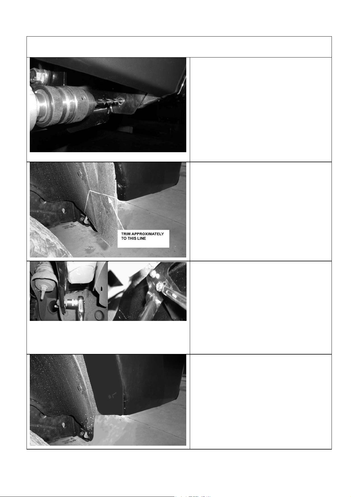
4.2 Trim excess plastic inner guard molding to
meet lower profile of bull bar wing. Note
the position of water bottle on LHS of
vehicle and trim neatly around it.
4.3 Fit washer bottle protection frame to
lower mounts where original bumper
stabiliser arms were located using 2 x
M10 x 30 bolt and washer sets. Fit off
the upper bracket to inner wing area of
bull bar as shown using M8 x 25 bolts
and washer sets.
NOTE: The 2 x M8 cage nuts should be in
place from step 2.7.
11/10/05 Page 12 of 14 3783177
Page 41

4.4 Fit inner guard plates to ends of bull bar
wings and fasten with M6 black screws
and washers.
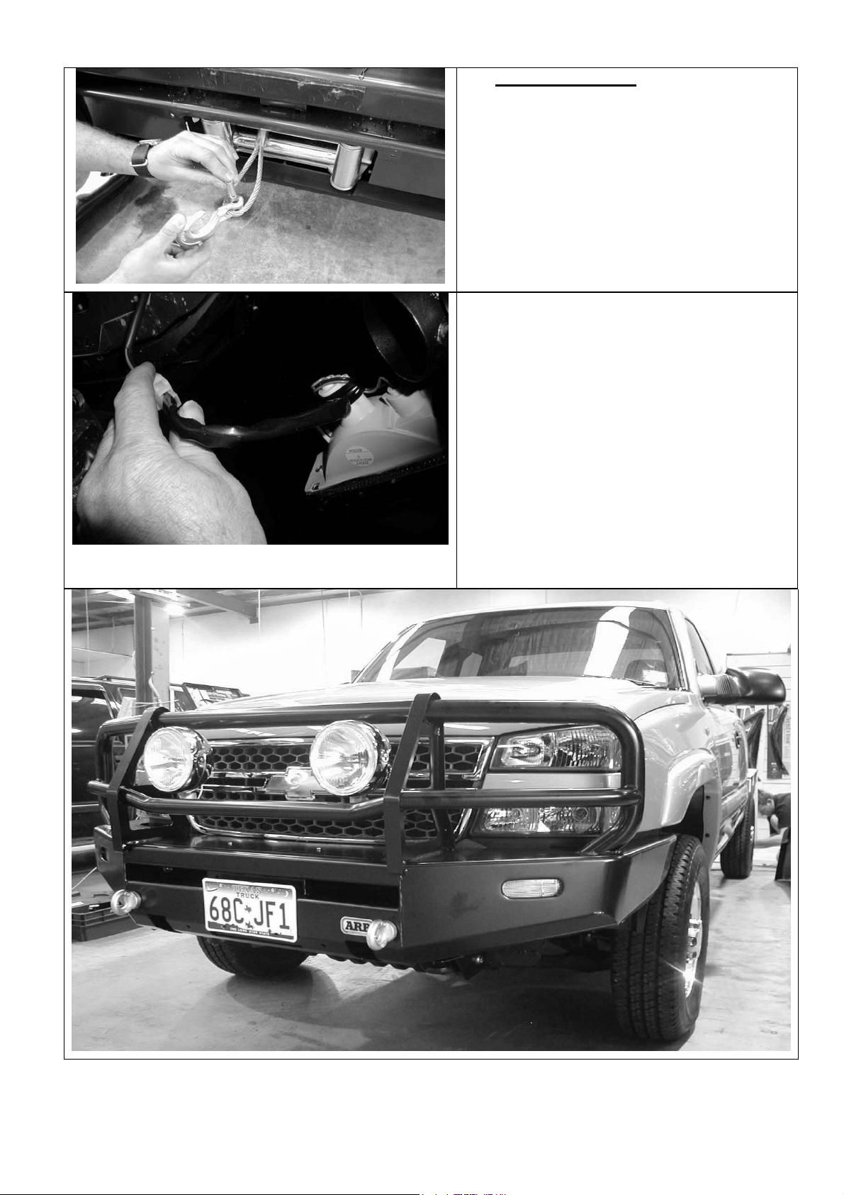
4.5 If fitting with winch
With the winch cable through the roller fair
lead. Mount the hook to the end of the
cable.
4.6 Wire up the indicator and clearance lamp
assemblies. Use scotch locks to splice
cables to existing indicator and clearance
lamp wiring and cable tie securely.
If fog lights are to be installed, mount
positions are on lower pan area between
winch opening and high lift jack position.
Refer to the Warn winch manual for
vehicle wiring instructions.
Ensure that electrical cables are installed
well clear of sharp, hot or moving objects.
Secure the winch cables to the vehicle
and winch bumper with the supplied cable
ties.
11/10/05 Page 13 of 14 3783177
Page 42

11/10/05 Page 14 of 14 3783177
Page 43

ARB COMBINATION WINCH, NON-WINCH BULL BAR TO SUIT
CHEVROLET SILVERADO 03 ON 2500HD-3500 MODELS.
PRODUCT No. 3462020, WITH FITTING KIT 3562060
WARNING
FOR VEHICLES EQUIPPED WITH SRS AIRBAG
WHEN INSTALLED IN ACCORDANCE WITH THESE INSTRUCTIONS, THE FRONT
PROTECTION BAR DOES NOT AFFECT OPERATION OF THE SRS AIRBAG.
TAKE NOTE OF THE FOLLOWING:
• THIS PRODUCT MUST BE INSTALLED EXACTLY AS PER THESE
INSTRUCTIONS USING ONLY THE HARDWARE SUPPLIED.
• IN THE EVENT OF DAMAGE TO ANY BULL BAR COMPONENT,
CONTACT YOUR NEAREST AUTHORISED ARB STOCKIST. REPAIRS OR
MODIFICATIONS TO THE IMPACT ABSORPTION SYSTEM MUST NOT BE
ATTEMPED.
• DO NOT USE THIS PRODUCT FOR ANY VEHICLE MAKE OR MODEL,
OTHER THAN THOSE SPECIFIED BY ARB.
• DO NOT REMOVE LABELS FROM THIS BULL BAR.
• THIS PRODUCT OR ITS FIXING MUST NOT BE MODIFIED IN ANY WAY.
Note :
• This bull bar is suitable for Warn 9,500-16,500lb winches.
• Fog light provisions are in lower pan area of bull bar. IPF840FYS lights
are suitable for this location.
Tools Required
Metric Spanner and Socket set Allen key set
Phillips head screwdriver Dia 5.5, 10.0 and 12.0mm drill bits
Electric drill 13mm chuck Sikaflex 227 adhesive, black color
11/10/05 Page 1 of 13 3783178
If you have any queries regarding the installation of this product please contact the distributor from whom it was purchased, or alternatively the ARB office in your state.
WA: (08) 9244 3553 NSW: (02) 9821 3633 ACT: (02) 6280 7475 SA: (08) 8244 5001 QLD: (07) 3872 3872 NT: (08) 8947 2262 TAS: (03) 6331 4190
Head Office – ARB Corporation Ltd VIC: 42-44 Garden Street, Kilsyth, Victoria, 3137 Tel: (03) 9761 6622 Fax: (03) 9761 6807
Page 44

USE PART No QTY DESCRIPTION
MOUNT BRACKETS TO VEHICLE 3756787L 1 BRACKET BAR MOUNT LHS
3756787R 1 BRACKET BAR MOUNT RHS
4581060 2 WASHER 13X30X3
4581049 14 M12 WASHER FLAT
4581050 8 M12 WASHER SPRING
6151255 8 BOLT M12 X 40
6151189 6 NUT M12x1.75
5848316 2 PACKER
WINCH 180302 8 CABLE TIE
TOW HOOK RELOCATION 6151365 2 EYEBOLT M24 2.5 SWL
6151361 2 NUT M24 GR8 ZP
3756765 2 BRACKET NUT RETAINING
4581300 2 WASHER M24 EYEBOLT
6151046 2 WASHER M6
6151017 2 BOLT M6 X 16mm
6151128 2 NUT FLANGE M6
CONTROL BOX FITTMENT 4581291 2 WASHER M10 BZ
6151321 2 NUT FLANGED
6151364 2 SCREW CAP M10X30 ZP
3756775 1 BRACKET STD CONTROL BOX IN PAN
3199790 1 TRIM PLATE FOR 16500LB CONTROL
NUMBER PLATE FITTMENT 6151017 4 BOLT M6 X 16mm
6151128 4 NUT FLANGE M6
6151046 4 WASHER M6
3751384 1 BRACKET NO.PLATE
WINCH COVER FITTMENT 6151128 2 NUT FLANGE M6
6151256 2 SCREW M6 S/STEEL BUTTON HEAD
6151046 2 WASHER M6
6191013 1 EXTRUSION WINCH COVER @ 1757
6522048 1 PANEL WINCH COVER
11/10/05 Page 2 of 13 3783177
Page 45

BAR TO MOUNT ASSEMBLY 6151255 6 BOLT M12 X 40mm
4581050 6 WASHER SPRING M12
4581049 12 WASHER FLAT M12
4581048 2 WASHER SPRING M10
6151321 2 NUT M10 FLANGED
6151232 2 BOLT M10 X 30mm
4581040 2 WASHER FLAT 3/8”
6151189 4 NUT M12x1.75
INDICATOR ASSY 6821151R 1 INDICATOR ASSY RHS
6821151L 1 INDICATOR ASSY LHS
6151308 4 SCREW SELF TAPPING
6821116 4 NUT NYLON PLUG
6821152 2 LOOM
180701 6 SCOTCH LOCKS
180302 4 CABLE TIE
INNER GUARD RETAINER 3199787R 1 PLATE INNER GUARD
3199787L 1 PLATE INNER GUARD
6151128 4 NUT FLANGE M6
6151213 4 SCREW M6X20 BZ
4581082 4 WASHER M6X20 BZ
NOTE: Shipping brackets connecting
bull bar to pallet and associated
fasteners are not intended to be reused
in fitted bar assembly.
11/10/05 Page 3 of 13 3783177
Page 46

ASSEMBLY SEQUENCE FOR WINCH BUMPER.
1. FITTING MOUNTING BRACKETS
1.1 Remove plastic shroud above radiator as
shown, by releasing plastic clips
1.2 To remove the grille, carefully push the
retainer spring clips back out in four
places behind grille. Pull outer bar from
between headlights forward to release
from clip into end of guard. NOTE: It may
be necessary to remove top headlights to
gain access to these clips if you cannot
release them easily
1.3 Remove bumper by undoing four bolts
from above and behind bumper then two
bolts securing bumper to wing support
braces from under and behind forward of
wheel arch area.
11/10/05 Page 4 of 13 3783177
Page 47

1.4 Remove and replace tow hooks on
opposite chassis sides. Note, the hole
underneath the chassis may need to be
elongated to allow the bolt to fit into the
rear underside position. Leave the outer
bolt off.
1.5 Fit the mount brackets as shown, to the
end of the chassis rails, top M12 bolt and
washer set as shown finger tight only.
1.6 Slide in ‘L’ shaped packer oriented as
shown
1.7 Fit M12 bolt, spring washer and Dia
13.0x30x3 large washer into tow hook
thread, insert M12 bolt and washer set in
pinning hole to line up packer hole.
Tighten up lower bolt.
Remove loose bolt from pinning hole and
drill through using Dia12.0 drill. Then
insert and do up M12 bolt set.
11/10/05 Page 5 of 13 3783177
Page 48

1.8 Remove loose bolt from pinning hole and
drill through using Dia12.0 drill. Then
insert and do up M12 bolt set.
1.9 Drill pinning hole in top position as shown
then insert and do up M12 bolt set.
1.10 Tighten up all bolts
11/10/05 Page 6 of 13 3783177
Page 49

2. PREPARING BULL BAR FOR FITTING
2.1 Remove lights from cartons and then
remove screws and speed nuts from each
light. These fasteners are not to be reused
– new screws are supplied in the fitting kit.
2.2 Insert nylon nuts into square holes in light
brackets inside wing area
2.3 Fit lights using screws supplied in fitting
kit, taking note of RH and LH light bodies,
they are different and must be placed on
the correct side of bull bar.
11/10/05 Page 7 of 13 3783177
Page 50

2.4 Fit large eyebolt nut into the plate on the
inside of the bar.
2.5 Screw in the eyebolt using the large
washer. Eyebolt can be positioned to sit
vertically by rotating the large nut to the
correct position.
NOTE: EYEBOLTS SHOULD BE REMOVED
FOR SAFETY REASONS WHEN
TRAVELLING ON PUBLIC ROADS.
2.6 When the large nut is in its final position,
secure with the nut retaining bracket using
an M6 bolt, washer and flange nut.
2.7 Secure the number plate bracket using M6
bolts, flat washers and flange nuts. Attach
the longer side to the bullbar and the
shorter side to the number plate.
11/10/05 Page 8 of 13 3783177
Page 51

3. IF FITTING WINCH
3.1 As supplied the winch handle should be in
the position as shown.
Remove cable retaining band and position
cable loop so it will go through roller
fairlead when it is placed in bull bar.
3.2 Fit control box to pan:
• For 9500-12000lb winches, use
universal control box bracket supplied,
attaching to rear of control box mount
studs.
• Slide bracket flange under pan and
align with mount slots.
• Fasten in position with 2 x M10 cap
screws, black washers and flange nuts.
• For 15000lb winches, use Warn
supplied control box bracket, attaching
to rear of control box mount studs.
• Slide bracket flange under pan and
align with mount slots.
• Fasten in position with 2 x M10 cap
screws, black washers and flange nuts.
11/10/05 Page 9 of 13 3783177
Page 52

• For 16500lb winches, apply Sikaflex (or
similar product) to rear of control box
trim plate from fitting kit (note
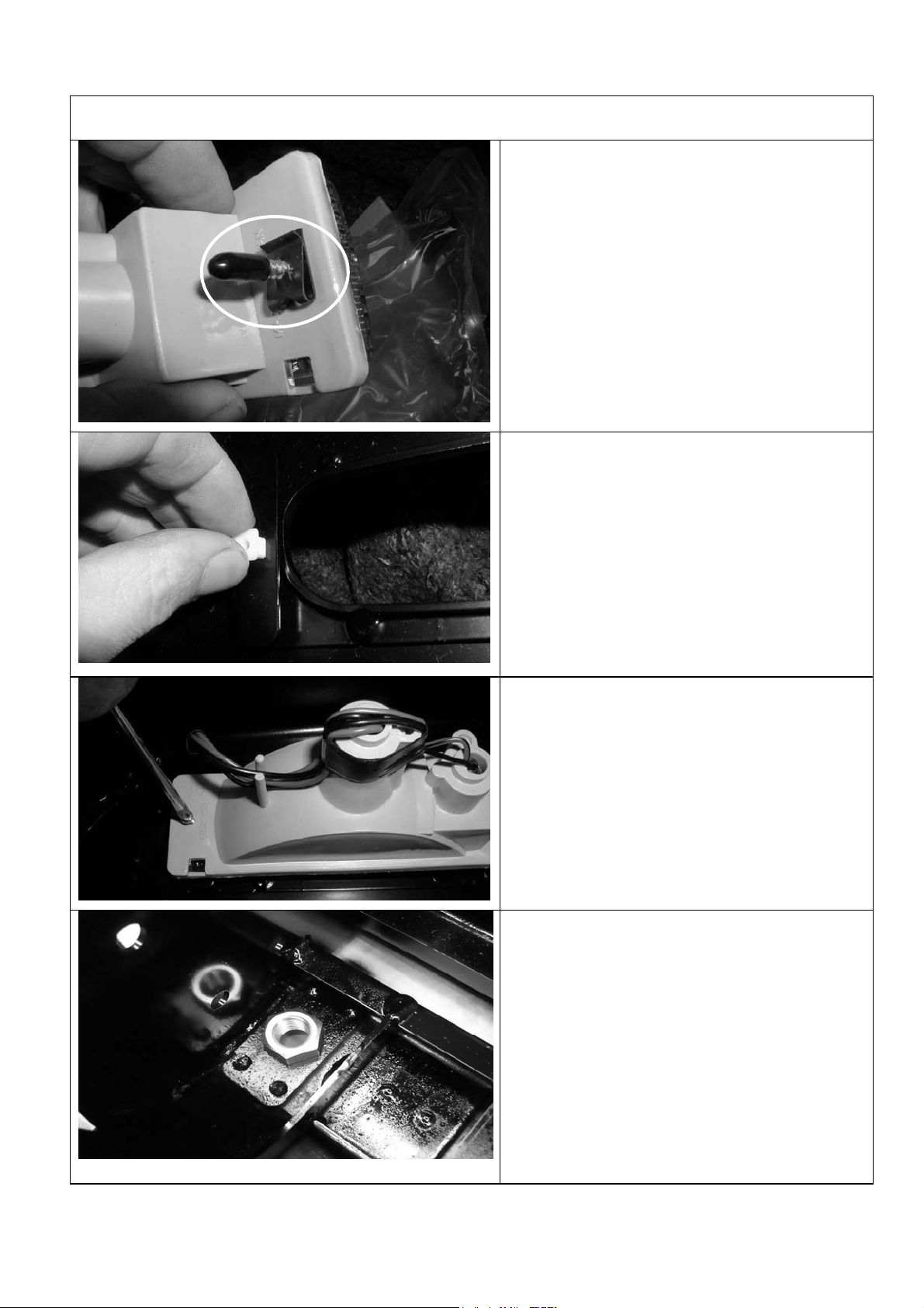
orientation critical to suit final position
with control box profile in pan opening).
• Position trim plate on top of pan
centrally about control box opening and
line up with mount slots.
• Fasten in position with 2 x M10 cap
screws and flange nuts from fitting kit.
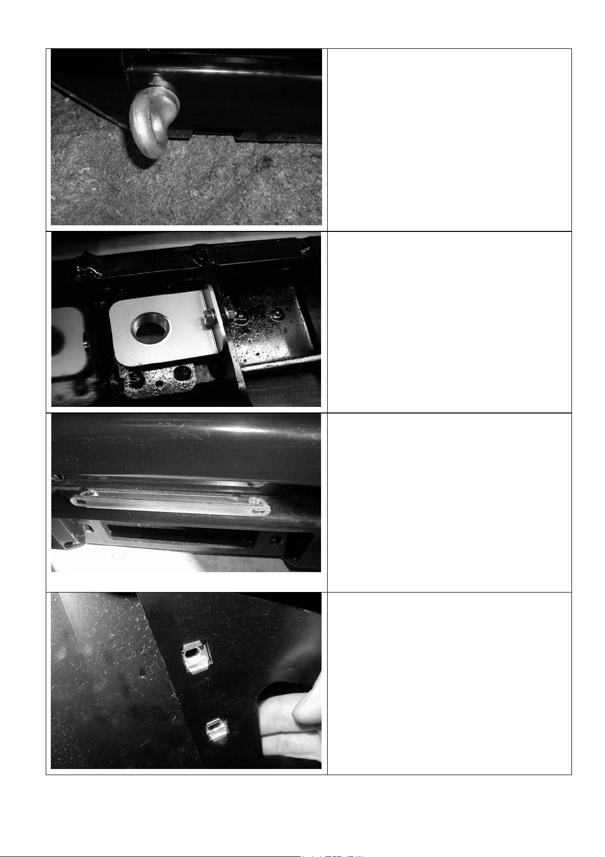
3.3 On some models, the roller fair lead must
be drilled prior to fitment.
Mark out as shown and using a 13.0 mm
drill bit, drill two holes as shown in
diagram.
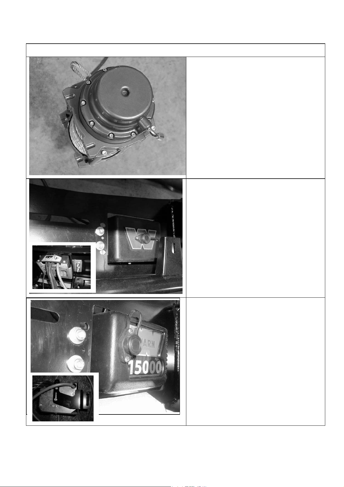
3.4 Viewed from front of vehicle the winch
clutch (handle) must be positioned on the
LH side (same side as smaller square
access hole in pan). Cable must spool
from the bottom of winch. Draw off
enough cable so cable crimp can be
pulled through roller fairlead.
Hint: If crimp is too large to fit through, remove
a circlip from a horizontal roller, partially
remove the shaft so roller gap is increased and
feed cable and crimp through. Refit shaft and
circlip.
Bolt winch in position with the roller fair lead in
place.
Hint: To increase access to mount bolts in
front of roller fairlead, remove circlips from
bottom of each vertical roller shaft, push shaft
up so roller can be dislodged sideways. Do up
bolts in fairlead and winch, then refit circlip.
Connect the winch control box cables to the
winch motor. Refer to the Warn handbook for
additional information. Connect the long winch
+ & - cables to the vehicle after the bar is
installed. Refer to the Warn winch manual
for vehicle wiring instructions.
11/10/05 Page 10 of 13 3783177
Page 53

3.5 Fitting number plate – with winch
Bolt number plate to the bracket with the
M6 X 16mm bolts and M6 flange nuts
through the lower holes of the number
plate.
Fitting with winch, number plate above RFL
Fitting without winch, number plate covers RFL
opening
If not fitting winch.
Bolt the number plate through the top
holes using M6 X 16mm bolts and M6
flange nuts.
3.6 If not fitting winch cont.
Wrap rubber extrusion around winch
cover.
Place washers over the winch cover fixing
holes located on the top middle face of the
winch bumper.
View from above, rear of bull bar
Place the winch cover on top of the winch
bumper inline with the mount holes.
Bolt together using the M6 button head
stainless steel screws and M6 nuts.
11/10/05 Page 11 of 13 3783177
Page 54

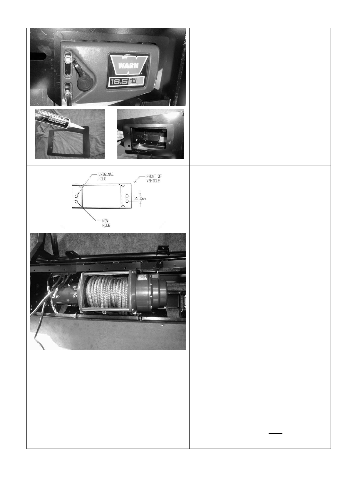
4. FITTING BULL BAR TO VEHICLE
4.1 Using two people, three if winch fitted,
position the bar assembly on the vehicle
mounts.
Bolt the bar to the mounts using M12
bolts, large flat washers and spring
washers. Align the bar to the profile of the
guards, grille and light profile and tighten
all bolts.
Using the M10 pilot holes in mount
brackets, drill pinning hole through
uprights on bull bar. Fit M10 screw,
washer set and flange nut and do up tight.
4.2 Trim excess plastic inner guard molding to
meet lower profile of bull bar wing. Note
the position of water bottle on LHS of
vehicle and trim neatly around it.
4.3 Fit inner guard plates to ends of bull bar
wings and fasten with M6 black screws
and washers.
4.4 If fitting with winch
With the winch cable through the roller fair
lead. Mount the hook to the end of the
cable.
11/10/05 Page 12 of 13 3783177
Page 55

4.5 Wire up the indicator and clearance lamp
assemblies. Use scotch locks to splice
cables to existing indicator and clearance
lamp wiring and cable tie securely.
If fog lights are to be installed, mount
positions are on lower pan area between
winch opening and high lift jack position.
Refer to the Warn winch manual for vehicle
wiring instructions.
Ensure that electrical cables are installed well
clear of sharp, hot or moving objects. Secure
the winch cables to the vehicle and winch
bumper with the supplied cable ties.
11/10/05 Page 13 of 13 3783177
 Loading...