

Page 1
Part Number: 3450130 F/KIT: 6172092
Product
COMBINATION BULL BAR
Description:
Suited to
WH/WK JEEP GRAND CHEROKEE 2005 ON
vehicle/s:
WARNING
REGARDING VEHICLES EQUIPPED WITH SRS AIRBAG;
When installed in accordance with these instructions, the front protection bar does not affect
operation of the SRS airbag.
ALSO, NOTE THE FOLLOWING:
♦ This product must be installed exactly as per these instructions using only the hardware supplied.
♦ In the event of damage to any bull bar component, contact your nearest authorised ARB stockist.
Repairs or modifications to the impact absorption system must not be attempted.
♦ Do not use this product for any vehicle make or model, other than those specified by ARB.
♦ Do not remove labels from this bull bar.
♦ This product or its fixing must not be modified in any way.
♦ The installation of this product may require the use of specialized tools and/or techniques
♦ It is recommended that this product is only installed by trained personnel
♦ These instructions are correct as at the publication date. ARB Corporation Ltd. cannot be held
responsible for the impact of any changes subsequently made by the vehicle manufacturer
♦ During installation, it is the duty of the installer to check correct operation/clearances of all
components
♦ Work safely at all times
♦ Unless otherwise instructed, tighten fasteners to specified torque
ARB 4x4 ACCESSORIES
Corporate Head Office
42-44 Garden St Tel: +61 (3) 9761 6622
Kilsyth, Victoria Fax: +61 (3) 9761 6807
AUSTRALIA 3137
Australian enquiries sales@arb.com.au
North & South American enquiries sales@arbusa.com
Other international enquiries exports@arb.com.au
Last Rev Date: 19/04/06 Page 1 of 22 Fitting instructions# 3783216
Copyright © 2005 by ARB Corporation Limited. All rights reserved, this document must not be reproduced without the express authority of ARB Corporation Ltd
Page 2
www.arb.com.au
GENERAL CARE AND MAINTENANCE
By choosing an ARB Bar, you have bought a product that is one of the most sought after 4WD products
in the world. Your bar is a properly engineered, reliable, quality accessory that represents excellent
value. To keep your bar in original condition it is important to care and maintain it following these
recommendations.
• Prior to exposure to the weather your bar should be treated to a Canuba based polish on all exposed
surfaces. It is recommended that this is performed on a six monthly basis or following exposure to
salt, mud, sand or other contaminants.
• As part of any Pre Trip Preparation, or on an annual basis, it is recommended that a thorough visual
inspection of the bar is carried out, making sure that all bolts and other components are torqued to the
correct specification. Also check that all wiring sheaths, connectors, and fittings are free of damage.
Replace any components as necessary. This service can be performed by your local authorized ARB
stockist.
HAVE AVAILABLE THESE SAFETY ITEMS WHEN FITTING PRODUCT:
BASIC TOOL KIT KEY HOLE SAW
Protective eyewear
NOTE: ‘WARNING’ notes in the fitting procedure relate to OHS situations, where to avoid a potentially
hazardous situation it is suggested that protective safety gear be worn or a safe work procedure be employed. If
these notes and warnings are not heeded, injury may result.
Hearing protection
FASTENER TORQUE SETTINGS:
SIZE Torque Nm Torque lbft
M6 9Nm 4lbft
M8 22Nm 16lbft
M10 44Nm 32lbft
M12 77Nm 57lbft
NOTE: IF YOUR VEHICLE IS NOT FITTED WITH FOG LIGHTS
YOU CAN PURCHASE A FOG LIGHT KIT FROM JEEP PART NO. 82209301
Last Rev Date: 19/04/06 Page 2 of 22 Fitting instructions# 3783216
Copyright © 2005 by ARB Corporation Limited. All rights reserved, this document must not be reproduced without the express authority of ARB Corporation Ltd
Page 3

USE PART No QTY DESCRIPTION
6151357 8 BOLT M10 x 1.5 x 30mm SEMS ASSY
6151090 2 BOLT M10 X 1.25 X 50mm
6151133 2 NUT M10 X 1.25
IMPACT ABSORBER 4581040 4 WASHER FLAT M10
MOUNTING SYSTEM 4581048 4 WASHER SPRING M10
6151304 8 NUT CAGED M10
3756904 1 MOUNT ASSEMBLY
5848328 2 PACKER MOUNT ASSY
4601172 L/R 2 CHANNEL CAPTIVE NUT (INSIDE CHASSIS RAILS)
3199854 2 PLATE CAPTIVE NUT (CROSSMEMBER TO CHASSIS)
6151291 2 BOLT M12 X 1.25 X 30mm (WITH EXTENSION PLATE)
6151133 2 NUT M10 X 1.25
4581049 4 WASHER FLAT M12
4581050
6151135
6151180
4581082
4581036
BULL BAR TO 6151357 8 BOLT M10 x 30mm SEMS ASSY
IMPACT ABSORBERS 6151304 6 NUT CAGED M10
4581040 2 WASHER FLAT M10
6151026 2 NUT M10 X 1.5
6151021 2 BOLT M8 x 20mm
CONTROL BOX BRACKET 4581046 2 WASHER FLAT M8
3751564 1 CONTROL BOX BRACKET
6151132 2 NUT FLANGE M8
.
NUMBER PLATE BRACKET 6151180 2 BOLT M6 x 20mm (BRACKET TO BAR)
6151046 4 WASHER FLAT M6 x 13mm
6151128 4 NUT FLANGE M6
6151180 2 BOLT M6 x 20mm (NUMBER PLATE TO BRACKET)
3751370 1 NUMBER PLATE BRACKET
TO BOLT INDICATORS TO 6821151L 1 INDICATOR
BAR 6821151R 1 INDICATOR
6821152 2 LOOM INDICATOR
6151308 4 SCREW SELF TAPPING 25
6821116 4 GROMMET NYLON SNAP IN TYPE
180701 6 SCOTCH LOCKS
3162466 L/R 2 BUFFERS 260 X 230 UPRIGHT B/BAR
BUFFERS 6151128 12 NUT FLANGE M6
AIR DEFLECTOR 6522662 1 AIR DEFLECTOR
6151262 3 BOLT M8 X 20mm BLACK
6151303 3 NUT CAGED M8 BLACK
4581045 3 WASHER FLAT M8 x 20mm
4581047 3 WASHER SPRING M8 BLACK
6522663 L/R 2 PANELS
UNDER WING PANEL 6151213 10 BOLT M6 x 20mm BLACK
4581082 10 WASHER FLAT M6 BLACK
4581287 10 WASHER SPRING M6 BLACK
6151128 2 NUT FLANGE M6
6151300 8 NUT CAGED M6
FOG LIGHT HOUSING 3162457 1 PLASTIC HOUSING RHS
AND FITMENT 3162456 1 PLASTIC HOUSING LHS
6821184 1 LOOM ( CABLE RED ) (CUT INTO 4 EQUAL LENGTHS )
180701 8 SCOTCH LOCKS
INNER GUARD TO BAR 6151213 4 BOLT M6 x 20mm BLACK
4581082 4 WASHER FLAT M6 x 20mm BLACK
6151128 4 NUT FLANGE M6
4581287 4 WASHER SPRING M6
180302 2 CABLE TIES
WINCH FITMENT 180302 8 CABLE TIES
6151073 2 BOLT 3/8” X 1 ½”
6151074 2 BOLT 3/8” X 1 ¾”
4581040
EG50
2
WASHER SPRING M12
2
NUT M12 X1.25
2
BOLT M6 x 20
2
M6 FLAT WASHER
2
M6 SPRING WASHER
4 2 WASHER FLAT M10
RUBBER GROMMET
Last Rev Date: 19/04/06 Page 3 of 22 Fitting instructions# 3783216
Copyright © 2005 by ARB Corporation Limited. All rights reserved, this document must not be reproduced without the express authority of ARB Corporation Ltd
Page 4
ASSEMBLY SEQUENCE FOR BULL BAR INSTALLATION.
PLEASE READ AND UNDERSTAND FITTING INSTRUCTIONS BEFORE
ATTEMPTING TO FIT BAR TO VEHICLE
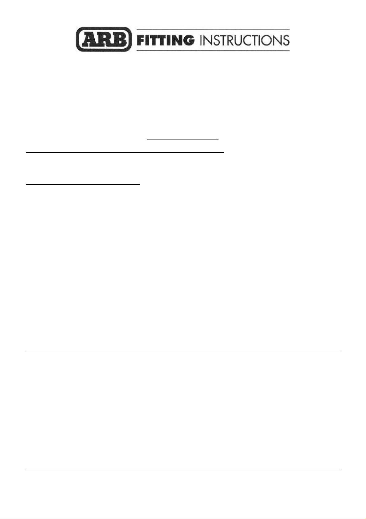
1. Remove grille from vehicle by
removing all plastic clips
Be careful when removing plastic
clips from grille as the plastic clips
are awkward to undo and will be
re used when refitting grille.
Slide flat blade screw driver under
pin of plastic clip and remove pin,
then lift out the plastic clip.
When all clips are removed, pull
GRILLE RETAINER PANEL
grill upward toward you.
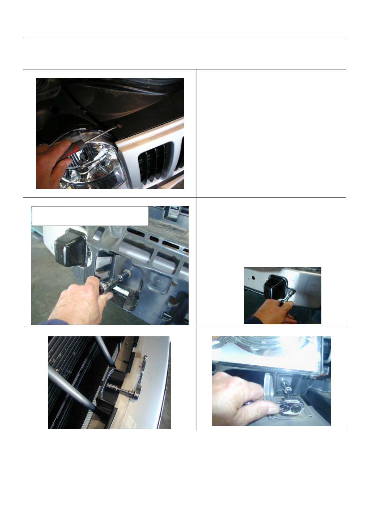
2. Remove lower plastic grille
retainer panel from vehicle and put
aside, as this panel will have to be
modified later.
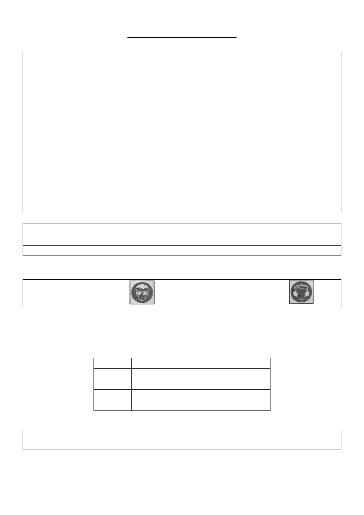
Remove tow hook and crush cans
from vehicle
Last Rev Date: 19/04/06 Page 4 of 22 Fitting instructions# 3783216
Copyright © 2005 by ARB Corporation Limited. All rights reserved, this document must not be reproduced without the express authority of ARB Corporation Ltd
Page 5
3. To remove bumper bar where
the inner guard is attached, push
plastic pin inward , then pull out
plastic retainer clip. Remove fog
lights and fog light adjuster and
the black plastic grommets from
bumper.
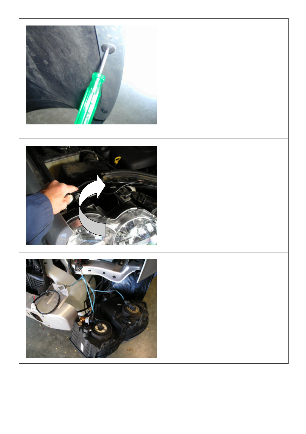
4. To remove headlights from
vehicle for ease of joining indicator
looms and extending fog light
looms, firstly lift plastic cover from
above headlight and undo one
plastic retaining clip and three
6mm bolts, then remove headlights.
5. After removing headlights from
vehicle, remove some of the blue
insulating tape from vehicle
indicator and parking looms to
expose wiring to be able to fit
connectors.
Last Rev Date: 19/04/06 Page 5 of 22 Fitting instructions# 3783216
Copyright © 2005 by ARB Corporation Limited. All rights reserved, this document must not be reproduced without the express authority of ARB Corporation Ltd
Page 6
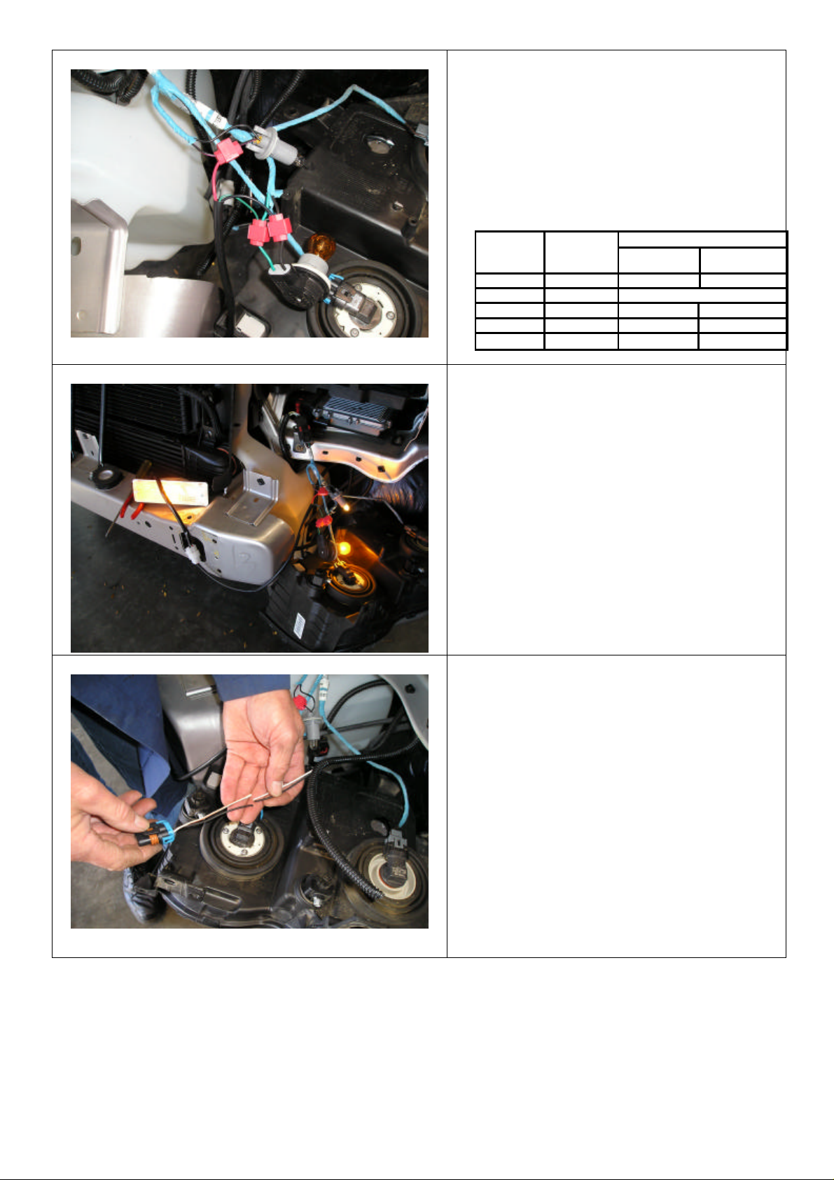
6. Use scotch locks to connect wiring.
Summary of Wire Connections
SIGNAL
HARNESS
PARK LAMP RED BLACK / PINK BLACK / PINK
EARTH BLACK BLACK BLACK
INDICATOR GREEN GREEN GREEN
VEHICLE PARK LAMP FUNCTION TURN
RIGHT LEFT
VEHICLE INDICATOR
RIGHT LEFT
7. Test all lighting at this stage.
8 . To refit fog lights to bar, the
loom must be extended.
9. Cut the fog light loom in half
and then cut the 1.3 metre red
wire, ( supplied in bar fitting kit )
into four equal lengths ( i.e.
325mm each )
Last Rev Date: 19/04/06 Page 6 of 22 Fitting instructions# 3783216
Copyright © 2005 by ARB Corporation Limited. All rights reserved, this document must not be reproduced without the express authority of ARB Corporation Ltd
Page 7
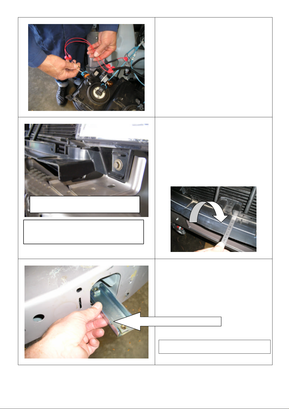
PANEL IDENTIFICATION
10. Scotch lock the red wire in
between the fog light loom making
sure the colour code matches.
11. When all wiring is completed.
Refit headlights back into vehicle.
REFER TO PARAGRAPH 2 FOR
PHOTO OF REFITTED PANEL OF
LEFT CORNER OF VEHICLE
12. Next step is to cut grille
retainer panel so bar can be fitted.
13. From the photo below mark
out a parallel line of 45mm and
cut off panel not required using a
jig saw or a key hole saw, then
refit back to vehicle.
14. Fit M10 caged nuts into
channel ( channels are L/RHS )
then fit channels inside of chassis
rails
Last Rev Date: 19/04/06 Page 7 of 22 Fitting instructions# 3783216
Copyright © 2005 by ARB Corporation Limited. All rights reserved, this document must not be reproduced without the express authority of ARB Corporation Ltd
Notch in channel must face inward
Page 8

TO BE REMOVED
PHOTO IS OF RHS OF VEHICLE
15. Using a 6mm drill bit, drill
two holes approximately 50mm
apart through the plastic inner
guard and the outer edge of the
plastic splash panel.
16. Cable tie these two panels
together
17. Remove alarm device from RHS
of crossmember by unscrewing
two 6mm bolts
18. Replace this part when chassis
mount assembly is fitted.
ARROWS INDICATE BOLTS
19. Lift chassis mount assembly onto
vehicle crossmember.
20. Using black M6mm x 20 bolt ,
spring / flat washer, secure to
vehicle as per photo.
21. Make sure mount assembly is
lifted up hard against bottom of
chassis rails, then tighten 6mm
bolts. ( These bolts are only to
position mount assembly to
vehicle.
Last Rev Date: 19/04/06 Page 8 of 22 Fitting instructions# 3783216
Copyright © 2005 by ARB Corporation Limited. All rights reserved, this document must not be reproduced without the express authority of ARB Corporation Ltd
Page 9

22. As viewed from underneath on
LHS of vehicle, align rear hole of
mount assembly to previously
fitted captive nut channel, secure
using M10 bolt x 30mm SEMS (
Bolt, Spring and Flat Washer
ASSY. )
23. Finger tighten only.
24. Carry out fixing to both sides of
vehicle.
NOTE: ‘WARNING’ notes in the
fitting procedure relate to OHS
situations, where to avoid a potentially
hazardous situation it is suggested that
protective safety gear be worn or a safe
work procedure be employed. If these
notes and warnings are not heeded,
injury may result.
25. Using a 10mm drill bit, drill hole
through chassis rail,using hole in
mount as a template. Be careful
not to drill into the nut in captive
nut channel.
26. Secure using bolts same as above,
when all four bolts are fitted,
tighten securely.
Last Rev Date: 19/04/06 Page 9 of 22 Fitting instructions# 3783216
Copyright © 2005 by ARB Corporation Limited. All rights reserved, this document must not be reproduced without the express authority of ARB Corporation Ltd
Page 10

Warning: Drilling operations can result in flying
Warning: Drilling operations can result in flying
27. Using holes in chassis mount
assembly as a template, drill
through crossmember on both
sides using 10mm drill bit.
metal debris, safety glasses should be worn.
28. Also drill through top of mount
into vehicle crossmember,
making sure that you are drilling
perpendicular.
metal debris, safety glasses should be worn.
29. Fit packer in between mount
assembly and vehicle
crossmember and align with the
two holes.
Last Rev Date: 19/04/06 Page 10 of 22 Fitting instructions# 3783216
Copyright © 2005 by ARB Corporation Limited. All rights reserved, this document must not be reproduced without the express authority of ARB Corporation Ltd
Viewed from above on LHS of vehicle
Page 11

LHS OF VEHICLE
30. Fit M10 caged nuts into captive
nut plate, then align with
previously drilled front holes.
31. Secure using M10 bolts (SEMS)
finger tighten only.
VIEWED FROM LHS
32. Insert M12 Tagged bolt / flat
washer into the chassis rail and
pass through 12mm hole in
chassis rail.
33. Fit through hole in captive nut
plate and secure with flat , spring
washer and 12mm nut.
34. Finger tighten only
11
35. Fit a M10 bolt x 50mm (fine
thread) and a flat washer up from
inside chassis rails, through
packer and chassis mount assy
and secure with a flat, spring
washer and 10mm nut.
36. At this stage all bolts are fitted to
vehicle. Know they can all be
tightened.
Last Rev Date: 19/04/06 Page 11 of 22 Fitting instructions# 3783216
Copyright © 2005 by ARB Corporation Limited. All rights reserved, this document must not be reproduced without the express authority of ARB Corporation Ltd
Page 12

37. Tighten this 12mm bolt each
side using universal joint and ½”
drive extension.
38. Refit alarm device at this stage.
39. Fit nylon grommets into square
holes to mount indicator / parker
lamps
Last Rev Date: 19/04/06 Page 12 of 22 Fitting instructions# 3783216
Copyright © 2005 by ARB Corporation Limited. All rights reserved, this document must not be reproduced without the express authority of ARB Corporation Ltd
Page 13

using 8mm hardware.
40. Remove the fastening screws
and nuts supplied with the turn
signal/clearance lamps and replace
these with the four screws provided
in the kit. Fasten the lamps to the
bar as shown.
IMPORTANT
The turn signal is to the inside of
the bar.
41. Fit M10 caged nuts to inside of
mounting face of bar.
Viewed from the RHS of the inside of bar
42. If bar is to have a winch fitted,
follow the next steps.
43. Fit number plate bracket using
6mm hardware (20mm x 6m
bolts )
44. Fit control box bracket to bar
Last Rev Date: 19/04/06 Page 13 of 22 Fitting instructions# 3783216
Copyright © 2005 by ARB Corporation Limited. All rights reserved, this document must not be reproduced without the express authority of ARB Corporation Ltd
( 20 x 8mm )
45. Fit rubber grommets to top of
bar.
Page 14

46. Drill 12mm holes under existing
holes 25mm lower down the same
pitch as existing holes, these will be
the holes used to bolt roller fairlead
to bar.
NEW HOLES
Warning: Drilling operations can result in flying
metal debris, safety glasses should be worn.
47. Fit buffers to bar using 6mm
flange nuts.
VIEWED FROM BEHIND BAR LHS
48. To fit winch into bar you must
pack winch up on a bench to enable
you to lower bar down on winch,
then fit four 3/8 ” square nuts into
winch lugs.
Last Rev Date: 19/04/06 Page 14 of 22 Fitting instructions# 3783216
Copyright © 2005 by ARB Corporation Limited. All rights reserved, this document must not be reproduced without the express authority of ARB Corporation Ltd
Page 15

49. Lower bar down over winch,
line up top holes first and secure
using 3/8” hardware (1 ½”” x
3/8”bolts) flat and spring washers.
50. Place roller fairlead over lower
holes and again secure using 3/8”
hardware (1 ¾”x 3/8” bolts) flat and
spring washers. When all bolts are
fitted tighten firmly.
51. Fit control box to control box
bracket using original ¼” nuts
from control box and connect
power cables to winch as per winch
instructions.
52. Cable tie power cables clear of
sharp edges and all moving parts.
53. Fit control box earth to winch
tie rods.
Last Rev Date: 19/04/06 Page 15 of 22 Fitting instructions# 3783216
Copyright © 2005 by ARB Corporation Limited. All rights reserved, this document must not be reproduced without the express authority of ARB Corporation Ltd
Page 16

54. Fit M8 caged nuts ( 3 OF ) into
lower section of bar.
( These nuts are to attached air
deflector pan to bar later on. )
55. Fit bar in between chassis
mounting assembly, align slots in
bar to caged nuts in mounting
assembly and secure using M10
bolts ( sems ) assy.
56. Adjust bar to vehicle and
tighten all bolts using socket,
extension and uni joint through fog
light aperture in bar.
57. Bar should have a 10-15mm gap
between bar surround and guard
line.
Last Rev Date: 19/04/06 Page 16 of 22 Fitting instructions# 3783216
Copyright © 2005 by ARB Corporation Limited. All rights reserved, this document must not be reproduced without the express authority of ARB Corporation Ltd
Page 17

TEMPLATE DRILLING HOLE.
58. Once the bar is secured to
vehicle, using holes in lower
section of bar as a template, drill
10mm holes through mounting
assembly and fix using 10mm
hardware.
(This bolt locks the bar to mounting
assembly. )
Warning: Drilling operations can result in flying
metal debris, safety glasses should be worn.
59. Using 6mm hardware, secure
plastic inner guard to top hole in
bar.
60. To secure lower hole, drill a
6mm hole through inner guard
aligning with hole in bar.
61. Next is to fit wing panels, firstly
fit M6 caged nuts to outer edges
of panel.
PHOTO IS OF LHS OF VEHICLE
ARROW INDICATES
Last Rev Date: 19/04/06 Page 17 of 22 Fitting instructions# 3783216
Copyright © 2005 by ARB Corporation Limited. All rights reserved, this document must not be reproduced without the express authority of ARB Corporation Ltd
Page 18

62. Fit panel on top of wing returns
and secure using 6mm hardware.
USE BLACK 6MM HARDWARE
63. Drill a 6mm hole into plastic
vehicle splash pan using hole in
wing panel as a template.
64. Secure using 6mm hardware.
Warning: Drilling operations can result in flying
metal debris, safety glasses should be worn.
SEE PARAGRAPH 61 FOR
HOLE LOCATION
65. After under wing panels are
all bolted up, using a key hole saw
etc, cut off the plastic under guard
which protrudes past the panels.
66. Dress up with a file.
Last Rev Date: 19/04/06 Page 18 of 22 Fitting instructions# 3783216
Copyright © 2005 by ARB Corporation Limited. All rights reserved, this document must not be reproduced without the express authority of ARB Corporation Ltd
Page 19

67. Undo the three 6mm bolts as
per photo so air deflector pan can
fit in between.
67. Fit front of air deflector to
underside of bar using black
8mm hardware.
68. Fit rear of air deflector using
original 6mm bolts. (refer to
paragraph 67.
69. If no fog lights are not going to
be fitted, fit light surround to
bar as is. If fog lights are going
to be fitted, cut out rear of
surround using a key hole saw
and remove rough edges with a
file.
Last Rev Date: 19/04/06 Page 19 of 22 Fitting instructions# 3783216
Copyright © 2005 by ARB Corporation Limited. All rights reserved, this document must not be reproduced without the express authority of ARB Corporation Ltd
Page 20

70. Light surround is held to bar
using silicon.
71. Apply a bead of silicon
around light cutout on bar and
hold fog light housing to bar
using masking tape until silicon
dries, then remove tape.
72. If fitting fog lights back into
vehicle, pull extended loom
through fog light mounting
bracket and refit black plastic
grommets back into square hole.
73. Reconnect fog light plug back
into light.
74 .Smear grease onto the light
mounting pivots to help when
sliding fog light back into
mounting bracket.
75. NB. When fitting light into
bracket, you must rotate light so
plug fits in between rear of
bracket and vehicle crossmember,
then push light rearward until
light click into bracket mounting
holes.
Last Rev Date: 19/04/06 Page 20 of 22 Fitting instructions# 3783216
Copyright © 2005 by ARB Corporation Limited. All rights reserved, this document must not be reproduced without the express authority of ARB Corporation Ltd
Page 21

OPTIONAL COLOUR CODE HOUSING
76. When light is fitted to bracket
refit adjuster screw then reset light
alignment.
IF YOUR VEHICLE IS NOT
FITTED WITH FOG LIGHTS,
YOU CAN PURCHASE A FOG
LIGHT KIT FROM JEEP.
Part no. 82209301.
77. Follow steps to fit light housing
to bar same as paragraph 71.
NB. Photo shows silicon applied
around fog light cutout.
78. Position for Hi lift jacking
point.
Last Rev Date: 19/04/06 Page 21 of 22 Fitting instructions# 3783216
Copyright © 2005 by ARB Corporation Limited. All rights reserved, this document must not be reproduced without the express authority of ARB Corporation Ltd
Page 22

79. The Warn roller fairlead cover
must be fitted to roller fairlead
when winch is not in use due to
protruding sharp edges
legislation.
Warn Part no. W25580
80. The cover requires the
lower side profile to be cut to fit
the bar centre section profile.
PHOTO SHOWS COLOUR CODED BAR
Last Rev Date: 19/04/06 Page 22 of 22 Fitting instructions# 3783216
Copyright © 2005 by ARB Corporation Limited. All rights reserved, this document must not be reproduced without the express authority of ARB Corporation Ltd
 Loading...